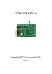
1
®
Safe-NET™
Software Version 9.03 or Later
Technician’s Manual
©2008 HUSSMANN CORPORATION • BRIDGETON, MO 63044-2483 U.S.A.
U.S. & CANADA 1-800-922-1919 • MEXICO 1-800-522-1900 • WWW.HUSSMANN.COM
July 2008
P/N 0461391_B
P/N 0461391_B
iii
CONTENTS
INTRODUCTION
What is Safe-NET . . . . . . . . . . . . . . . . . . . . . 1-1
Temperature Monitoring . . . . . . . . . . . . . . 1-1
Components . . . . . . . . . . . . . . . . . . . . . . . . . 1-1
Display Module . . . . . . . . . . . . . . . . . . . . . 1-2
Digital Sensors . . . . . . . . . . . . . . . . . . . . . . 1-2
Optional Wireless Hand-held Controller
and/or PC Control . . . . . . . . . . . . . . . . . . . 1-2
INSTALLATION
Self-Contained Case . . . . . . . . . . . . . . . . . . . 2-1
Three-Button Rules (V9.03) . . . . . . . . . . . . . 2-1
Alarms . . . . . . . . . . . . . . . . . . . . . . . . . . . . . 3-7
SEnS . . . . . . . . . . . . . . . . . . . . . . . . . . . . . . 3-7
noSn . . . . . . . . . . . . . . . . . . . . . . . . . . . . . . 3-7
dSHi . . . . . . . . . . . . . . . . . . . . . . . . . . . . . . 3-7
dSLo . . . . . . . . . . . . . . . . . . . . . . . . . . . . . . 3-7
CoM . . . . . . . . . . . . . . . . . . . . . . . . . . . . . . 3-8
PrHi . . . . . . . . . . . . . . . . . . . . . . . . . . . . . . 3-8
PrLo . . . . . . . . . . . . . . . . . . . . . . . . . . . . . . 3-8
Impact Multiple Coils . . . . . . . . . . . . . . . . 3-8
SC-C . . . . . . . . . . . . . . . . . . . . . . . . . . . . 3-8
SC-L . . . . . . . . . . . . . . . . . . . . . . . . . . . . 3-8
SC-r . . . . . . . . . . . . . . . . . . . . . . . . . . . . . 3-8
Door Open . . . . . . . . . . . . . . . . . . . . . . . . . 3-9
SAFE-NET DISPLAY & ALARM MODULES
MENUS
Description . . . . . . . . . . . . . . . . . . . . . . . . . . 3-1
Safe-NET Display Module . . . . . . . . . . . . 3-1
Alarm Module . . . . . . . . . . . . . . . . . . . . . . 3-1
Operation . . . . . . . . . . . . . . . . . . . . . . . . . . . 3-1
Normal . . . . . . . . . . . . . . . . . . . . . . . . . . . 3-1
Product Temperature Alarms . . . . . . . . . . 3-2
Power Failure . . . . . . . . . . . . . . . . . . . . . . 3-2
Low Battery . . . . . . . . . . . . . . . . . . . . . . . 3-2
Connection Failure . . . . . . . . . . . . . . . . . . 3-2
Precedence of Alarms . . . . . . . . . . . . . . . . 3-2
Alarm Set Points . . . . . . . . . . . . . . . . . . . . 3-3
Modifying ARL/ARV Settings . . . . . . . . . . 3-3
Password . . . . . . . . . . . . . . . . . . . . . . . . . . . 3-4
Modifying Set Points . . . . . . . . . . . . . . . . . . 3-5
Wiring Diagram for Display Module
and Alarm Module . . . . . . . . . . . . . . . . . . 3-6
Menu Presentation Conventions . . . . . . . . . 4-1
Menu Navigation Overview . . . . . . . . . . . . . 4-2
Time Outs . . . . . . . . . . . . . . . . . . . . . . . . . . 4-2
Password . . . . . . . . . . . . . . . . . . . . . . . . . . 4-2
Inactivity . . . . . . . . . . . . . . . . . . . . . . . . . . 4-2
Escape . . . . . . . . . . . . . . . . . . . . . . . . . . . . . 4-2
Clear . . . . . . . . . . . . . . . . . . . . . . . . . . . . . . . 4-3
Button Action . . . . . . . . . . . . . . . . . . . . . . . . 4-3
Display Symbol Identification . . . . . . . . . . . 4-4
Easy Access Menu . . . . . . . . . . . . . . . . . . . . 4-5
Top Level Menus . . . . . . . . . . . . . . . . . . . . . 4-6
Setup Menu . . . . . . . . . . . . . . . . . . . . . . . . . 4-9
Password Protection . . . . . . . . . . . . . . . . . 4-10
DSET . . . . . . . . . . . . . . . . . . . . . . . . . . . . 4-11
PSEN . . . . . . . . . . . . . . . . . . . . . . . . . . . . . 4-12
CNTN . . . . . . . . . . . . . . . . . . . . . . . . . . . . 4-13
DSPN . . . . . . . . . . . . . . . . . . . . . . . . . . . . 4-14
IMPORTANT
KEEP IN STORE FOR FUTURE REFERENCE
Quality that sets industry standards.
®
12999 St. Charles Rock Road • Bridgeton, MO 63044 U.S.A. • (314) 291-2000 • FAX (314) 298-4767
iv
CONTENTS (Continued)
RST . . . . . . . . . . . . . . . . . . . . . . . . . . . . . . 4-14
NSEN . . . . . . . . . . . . . . . . . . . . . . . . . . . . 4-15
LGHT . . . . . . . . . . . . . . . . . . . . . . . . . . . . 4-16
DEGR . . . . . . . . . . . . . . . . . . . . . . . . . . . . 4-17
DUTY . . . . . . . . . . . . . . . . . . . . . . . . . . . . 4-18
DIFF . . . . . . . . . . . . . . . . . . . . . . . . . . . . . 4-19
FSET . . . . . . . . . . . . . . . . . . . . . . . . . . . . . 4-20
CTRL . . . . . . . . . . . . . . . . . . . . . . . . . . . . 4-20
DCOT . . . . . . . . . . . . . . . . . . . . . . . . . . . . 4-21
PD-L . . . . . . . . . . . . . . . . . . . . . . . . . . . . . 4-22
PRHI . . . . . . . . . . . . . . . . . . . . . . . . . . . . . 4-23
PRLO . . . . . . . . . . . . . . . . . . . . . . . . . . . . 4-24
ADLY . . . . . . . . . . . . . . . . . . . . . . . . . . . . 4-25
HIGH . . . . . . . . . . . . . . . . . . . . . . . . . . . . 4-26
LOW . . . . . . . . . . . . . . . . . . . . . . . . . . . . . 4-27
INPT . . . . . . . . . . . . . . . . . . . . . . . . . . . . . 4-28
CASE . . . . . . . . . . . . . . . . . . . . . . . . . . . . . 4-29
Clock Menu . . . . . . . . . . . . . . . . . . . . . . . . . 4-30
Defrost Menu . . . . . . . . . . . . . . . . . . . . . . . . 4-31
DTYP . . . . . . . . . . . . . . . . . . . . . . . . . . . . 4-31
INDC . . . . . . . . . . . . . . . . . . . . . . . . . . . . . 4-33
STOP . . . . . . . . . . . . . . . . . . . . . . . . . . . . . 4-34
START . . . . . . . . . . . . . . . . . . . . . . . . . . . 4-34
FCTL . . . . . . . . . . . . . . . . . . . . . . . . . . . . . 4-35
TSET . . . . . . . . . . . . . . . . . . . . . . . . . . . . . 4-36
DURA . . . . . . . . . . . . . . . . . . . . . . . . . . . . 4-37
TTYP . . . . . . . . . . . . . . . . . . . . . . . . . . . . 4-38
STAR . . . . . . . . . . . . . . . . . . . . . . . . . . . . . 4-38
NDEF . . . . . . . . . . . . . . . . . . . . . . . . . . . . 4-40
Temperatures Menu . . . . . . . . . . . . . . . . . . . 4-40
Valve Menu . . . . . . . . . . . . . . . . . . . . . . . . . 4-42
CLAV . . . . . . . . . . . . . . . . . . . . . . . . . . . . 4-43
DSVR . . . . . . . . . . . . . . . . . . . . . . . . . . . . 4-43
DHVR . . . . . . . . . . . . . . . . . . . . . . . . . . . . 4-43
CSVR . . . . . . . . . . . . . . . . . . . . . . . . . . . . 4-43
CHVR . . . . . . . . . . . . . . . . . . . . . . . . . . . . 4-43
C-OF . . . . . . . . . . . . . . . . . . . . . . . . . . . . . 4-44
V-OF . . . . . . . . . . . . . . . . . . . . . . . . . . . . . . 4-44
NORL . . . . . . . . . . . . . . . . . . . . . . . . . . . . 4-45
CLOSE . . . . . . . . . . . . . . . . . . . . . . . . . . . 4-45
P/N 0461391_B
OPEN . . . . . . . . . . . . . . . . . . . . . . . . . . . . 4-45
SREF . . . . . . . . . . . . . . . . . . . . . . . . . . . . . 4-46
VTYP . . . . . . . . . . . . . . . . . . . . . . . . . . . . 4-46
VPOS . . . . . . . . . . . . . . . . . . . . . . . . . . . . 4-47
Display Default . . . . . . . . . . . . . . . . . . . . . . . 4-48
Dimmer . . . . . . . . . . . . . . . . . . . . . . . . . . . . 4-49
WARRANTY
REVISION HISTORY
Revision B July 2008
Version 9.03 Software updates
Revision A
November 2005
Original Version
January 2005
HUSSMANN CORPORATION, Bridgeton, MO 63044-2483 U.S.A.
1-1
P/N 0461391_B
INTRODUCTION
WHAT IS Safe-NET™
Safe-NET is an advanced, electronic system for
monitoring or controlling case temperatures in one or
more locations. It will help you ensure continuous,
reliable refrigeration and safer, fresher foods, 24 hours a
day.
The Safe-NET system is composed of sensors, harnesses,
control modules, display modules, relay modules and a
power supply.
Safe-NET technology provides an ideal system for
verifying and maintaining compliance with Federal
Department of Agriculture (FDA) and National
Sanitation Foundation (NSF) regulations. It uses a
standard communication protocol compatible with many
third party systems to enable communication with a PC.
Temperature Monitoring
Safe-NET lets you monitor temperatures in up to 10
different areas of each case: discharge air, return air,
product temperatures, coil inlet and outlet temperatures,
etc. Temperature readings are logged for later review. The
system sends an alarm if temperatures exceed predefined
limits.
Alarm Module
Power Supply
(Transformer)
Display Module
Sensor
Harness
Temperature Sensor
ARV / ARL
Kit Alarm
Typical Safe-NET™ Installation
COMPONENTS
All components of the Safe-NET system (displays,
sensors, and control modules) are factory installed. A
single case-to-case plug-in connector is all that is
required for field installation.
Typical Safe-NET™ Components
Hussmann Corporation • Bridgeton, Missouri 63044-2483 U.S.A.
Safe-NET™
1-2
INTRODUCTION
Optional Wireless Hand-held Controller and/or PC
Control
Display Module
The display module is a slim four-digit binary coded
decimal LED unit which mounts in the case fascia panel.
It lets you check temperatures at a glance and performs a
variety of other monitoring and control functions via
pushbuttons or the hand-held controller.
The wireless controller communicates with the display
unit through an infrared sensor. This allows setups and
queries which can also be performed via PC over the
network.
Safe-NET™ Display Module
Up to 10 sensors can be connected to each display
module.
Digital Sensors
Up to 10 digital sensors can be installed in each case with
a single cable connection. There are 14 types of sensors.
Each sensor has an electronic identifier so it can be
recognized by the display module. This eliminates the
need for separate wiring. Sensors in each case are
harnessed together to a single wire leading to the display
module. Sensors are designed for rugged durability.
Should a sensor fail, it can be replaced.
Safe-NET™ Hand Held Controller
If the wireless controller is not available, it is possible to
program the controller directly with buttons located on
the display module.
Typical Safe-NET™ Sensor Harness
P/N 0461391_B
U.S. & Canada 1-800-922-1919 • Mexico 1-800-522-1900 • WWW.HUSSMANN.COM
2-1
P/N 0461391_B
INSTALLATION
SELF-CONTAINED CASE
Safe-NET components are factory-installed. Once power
is supplied to the case as specified in the case’s installation
and service manual, Safe-NET settings are ready to be
selected.
When power is first applied, the Safe-NET display will
show the version of software installed. The initial scroll is
as follows: Safe — -Net — 9.03 (Version) — 570g
(Case Model) — 21 (default temperature display) .
The Version and Case Model will change dependant on
current version and case model selected.
Settings are retained when power is interrupted. Thus, a
self-contained case can be moved without re-entering
selected settings.
Startup of a new Self-Contained case is quite simple:
1. Verify case type selected.
2. Set the clock.
3. Check or set the temperature setpoint.
THREE BUTTON RULES (Version 9.03 Operation)
• Always start by pushing the SELECT button. Watch
what is displayed. Which menu are you in?
• For Case Models NIM and DDSS the menu sequence is
as follows:
EASY — dSEt — tSEt — StAr — durA — ndEF —
CLOC — PASS and cycles back to dSEt.
• For all other Case Models, the following sequence
applies:
EASY — dSEt — StAr — durA — ndEF — CLOC —
PASS and cycles back to dSEt.
• On all Case Models, after the passcode has been entered,
press the UP and DOWN buttons simultaneously to
escape from the Easy Access Menu. Subsequent presses of
the SELECT button will cycle through the top level
menus.
— StUP — CLOC — DEFr — tEM — VALv —
DiSP — and cycles back to StUP
• Press the SELECT button until you are in the proper
menu. Once in the proper menu press the UP or DOWN
button to enter the menu and to scroll through the menu.
• Once at the menu item that you want, press the
SELECT button until the item flashes between the value
and the title. You may have to press the SELECT button
more than once to get the item to flash.
• Press the UP or DOWN button to change the item.
• First press of the SELECT button enters the Easy
Access Menu (EAM). This menu displays commonly
viewed setpoints and information. It eliminates the need
to navigate multiple menus to retrieve these items. The
displayed items consist of two sets dependent upon the
Case Model Type.
Hussmann Corporation • Bridgeton, Missouri 63044-2483 U.S.A.
• Remember to push the SELECT button to save the item.
Also remember to set the passcode before items outside of
the Easy Access Menu can be changed.
• Pressing the UP or DOWN buttons at the same time
acts as an escape to go back out of the menus.
Safe-NET™
2-2
INSTALLATION
This page intentionally left blank.
P/N 0461391_B
U.S. & Canada 1-800-922-1919 • Mexico 1-800-522-1900 • WWW.HUSSMANN.COM
P/N 0461391_B
3-1
Safe-NET™ DISPLAY & ALARM MODULES
DESCRIPTION
Safe-NET Display Module
LED Indicators
The Safe-NET Display Module, shown in
Figure 1 and Figure 2, is a temperaturemonitoring device. The display module reads
and displays temperature sensed by the
product simulator temperature sensor mounted
in the refrigerated space. The display module
notifies the user of alarms based on preset
alarm conditions.
Figure 1. Safe-NET Display Module with Top Cover
SELECT Button
Alarm Module
The alarm module, shown in Figure 3, is an
additional feature to Safe-NET. The alarm
module supplies power to the display module
via an 8-wire cable. The alarm module provides
battery back up power to the display module
during loss of A.C. power. The display module
communicates with the alarm module via a
2-wire cable. Additionally, the alarm module is
equipped with a beeper to provide audible
notification of alarms.
UP Button
DOWN
DOWN Button
Button
Figure 2. Safe-NET Display Module with Cover Removed
Green LED
OPERATION
Normal
During normal operating conditions, the
product simulator temperature is displayed.
The GREEN LED on the alarm module is
lighted (as shown in Figure 3).
Figure 3. Safe-NET Alarm Module
Hussmann Corporation • Bridgeton, Missouri 63044-2483 U.S.A.
Safe-NET™
3-2
DISPLAY & ALARM MODULES
Product Temperature Alarms
The display module generates an alarm if the product
simulator temperature rises above the high alarm set
point or drops below the low alarm set point for the
preset time duration.
When the display module generates a high temperature
alarm, the RED LED on the display module is lighted.
Every 12 seconds, PrHi is displayed for 3 seconds; for the
remaining time, the product simulator temperature is
displayed.
When the display module generates a low temperature
alarm, the RED LED on the display module is lighted.
Every 12 seconds, PrLo is displayed for 3 seconds; for
the remaining time, the product simulator temperature is
displayed.
For either alarm, the beeper on the alarm board beeps
every 6 seconds.
Power Failure
If external power to the unit is interrupted, the backup
battery on the alarm board supplies power to maintain
the non-volatile memory in the display module.
To conserve power, the display LEDs are blanked except
for a period of 6 seconds every 3 minutes when product
temperature is displayed.
Product temperature alarms can be generated during
external power loss. The audible alarm is active only for
product temperature alarms.
P/N 0461391_B
Low Battery
During normal operating conditions, the alarm module
monitors battery condition. The display shows bAtt
when the battery becomes low on power and the beeper
on the alarm board beeps every 2 minutes to indicate a
low battery condition. The low battery audible alarm is
active only when external power is applied.
Connection Failure
Loss of communication between the display module and
the alarm module activates an alarm. When the display
module generates a loss of communication alarm, the
RED LED on the display module is lighted. Every 12
seconds, A-Er is displayed for 3 seconds; for the
remaining time, the product simulator temperature is
displayed. The beeper on alarm board beeps every
30 seconds. The A-Er audible alarm is active only when
external power is applied.
Precedence of Alarms
Severity of the alarm determines the beeper action. The
following table shows the priority of the alarms.
Alarm
Display
Action
Beeper
OFF Time
(seconds)
Severity
Product
HIGH/LOW
Alarm
PrHi/PrLo
6
1
Connection
Failure
A-Er
30
2
Low Battery
bAtt
120
3
U.S. & Canada 1-800-922-1919 • Mexico 1-800-522-1900 • WWW.HUSSMANN.COM
P/N 0461391_B
3-3
An alarm with higher severity takes precedence over a low
severity alarm. For example, if there is a product alarm
and low battery alarm:
• The alarm board beeper beeps every 6 seconds to
indicate the product temperature alarm.
• Indication of the low battery alarm is ignored by the
beeper, but is active in the display.
• Every 12 seconds, the display shows PrHi for 3 seconds
followed by bAtt for 3 seconds. For the remaining
time, product simulator temperature is displayed.
MODIFYING ARL/ARV SETTINGS
The Safe-NET display module stores alarm set points and
alarm delay times for monitoring ARL and ARV cases.
The suggested default set points may be modified.
Use a flat, narrow tool such as a small screwdriver to
remove the cover of the display module.
Alarm Set Points
Following are the alarm set points for ARL and ARV
cases:
Notes:
Product
Product Product Alarm
High Alarm Low Alarm
Delay
Set Point Set Point
(Minutes)
Case
Model
Set
Point
ARL
–8ºF
2ºF
–22ºF
90
ARV
36ºF
43ºF
32ºF
60
• A high temperature alarm typically activates during
case startup. This is normal since the refrigerated space
requires an extended period to reach operating
temperature. Product must not be loaded until operating
temperature is reached. Premature stocking may result in
product loss.
• Battery backup operation is possible for up to 6 hours.
The initial condition of the battery determines the length
of time. Operation of Safe-NET is compromised once the
battery runs low. Product integrity cannot be ensured
until power is restored and the battery is replaced.
Hussmann Corporation • Bridgeton, Missouri 63044-2483 U.S.A.
IMPORTANT!
• Hussmann recommends against changing
any parameter value other than those described
herein. Modification of any other parameter
may result in unpredictable Safe-NET operation.
• The user must monitor each case after
altering product alarm set points and/or product
alarm time delays to verify proper operation.
Safe-NET™
3-4
DISPLAY & ALARM MODULES
There are three visible buttons on the left hand side of
the display board, as indicated in Figure 2 on Page 1.
Although labels are not clear, buttons can be determined
by their location.
The SELECT button is located near the top edge of the
display board. It is used to select the menus and to edit
the menus.
The UP button is the left button of the two buttons
located on the bottom lineup of the display board. The
DOWN is the right button of the two buttons located on
the bottom lineup of the display board. The UP and
DOWN buttons are used to move within and between
menus, and to increment or decrement values.
Notes:
• The SELECT button is used to scroll through the
following menus:
EASy – Easy Access Menu
StUP – Setup
CLoC – Clock
dEFr
– Defrost
tEM
– Temperature
uALu – Valve
diSP
– Display Default
• User must enter valid password to edit protected
parameter settings and exit the Easy Access Menu.
Protected parameter settings are determined by Case
Model and the PSEn setting.
• To edit any menu item, press either the UP or DOWN
button to enter the selected menu.
• Use the SELECT button to modify and save the
parameter once the UP or DOWN button is pressed.
• The display cycles between menu item and edited menu
value once the edited value is entered using the SELECT
button.
• The display returns to showing the product simulator
temperature if no button is pressed for 12 seconds once
the menu is displayed. User must scroll through the
menus using the SELECT button to return to the SETUP
menu.
• Holding a button down has the same effect as pressing
once.
PASSWORD
Parameters that are critical to proper equipment
performance cannot be modified until a numeric
password is entered into the Safe-NET display module.
This prevents accidental or malicious changes in the SafeNET system from occurring.
The password is entered in the Easy Access Menu of the
display module, or in the SETUP menu when using a
Hand-held controller.
• On the Safe-NET display module, press the UP button
at the top of the Easy Access Menu.
• On the Hand-Held controller, press the UP button at
the top of the SETUP menu.
The display will begin to cycle between PASS and 0.
P/N 0461391_B
U.S. & Canada 1-800-922-1919 • Mexico 1-800-522-1900 • WWW.HUSSMANN.COM
P/N 0461391_B
While 0 is being displayed, press the SELECT button to
allow editing of the value. With the Safe-NET display
module flashing 0, use the UP /DOWN buttons to
increment or decrement the value until it reaches 595.
595 is the password value.
Once 595 is displayed, press the SELECT button. The
display will revert to cycling between PASS and 595. This
enables access to the top level menus for editing of
parameters.
The user may now navigate the menu system and edit
parameters as necessary.
Note:
The password protected access remains active for 5 minutes.
Each time a new parameter is entered by pressing the
ENTER key on the Hand-Held device or the SELECT
button on the Safe-NET display module, the 5 minute timer
is restarted. After 5 minutes with no parameter entries, the
password value reverts to 0 and the password entry process
must be performed to regain access to critical parameters.
Using the Hand-Held device, all menus can be navigated in
a “view only”mode without having entered a valid
password. When using the buttons, a valid password is
required to exit the Easy Access Menu and gain access to
the top level menus.
MODIFYING SET POINTS
With the password active and the display reading product
temperature, use the SELECT button to scroll through
the menus. Once the display reaches the StUP menu, use
the UP button until the display shows the parameter to
be modified:
Hussmann Corporation • Bridgeton, Missouri 63044-2483 U.S.A.
3-5
• To change the product low alarm set point, press the
UP button until the display cycles between PrLo and
the current product low alarm set point.
• To change the product high alarm set point, press the
UP button until the display cycles between PrHi and
the current product high alarm set point.
• To change the product alarm delay, press the UP
button until display cycles between P-dL and the
current product alarm delay.
Once the desired menu item is displayed, press SELECT
button. The display cycles between the corresponding
menu item and the VALUE. Press the UP button to
increment the value or the DOWN button to decrement
the value. The value of the parameter can be modified
only within the following specified ranges:
Case
Model
Range of
Product
High Alarm
Set Point
Range of
Product
Low Alarm
Set Point
Range of
Product
Alarm Delay
(Minutes)
ARL
–8ºF to 8ºF
–24ºF to –8ºF
0 to 240
ARV 36ºF to 52ºF
20ºF to 36ºF
0 to 240
When the entered value begins flashing, press the
SELECT button to store the new value. The display cycles
between the new value and the menu item. Within 12
seconds after button activation, the display starts
showing the product temperature.
Replace top cover of the display module after
modifications are complete. Verify that alarm LED
indicators are on the left side as shown in Figure 1 on
page 1.
Safe-NET™
3-6
DISPLAY & ALARM MODULES
Wiring Diagram for Display Module and Alarm Module
Safe-NET™
Battery Backup with Piezo Alarm, revision 1.01
06/17/05 MPK
Display Module
RS-485 unterminated
P2
RCVR
Alarm Module
alarm
status
P3
audible alarm
(piezo)
1
J4
1
2
2
ALARM
GROUND
1
2
1
2
RS-485B
ANTI-SWEAT
COMPRESSOR
GROUND
RS-485A
DEFROST
FANS
12VDC
1
2
3
4
5
6
7
8
1
2
3
4
5
6
7
8
12VDC
FANS
DEFROST
RS-485A
GROUND
COMPRESSOR
ANTI-SWEAT
RS-485B
8
red
blk
1
2
1
DRY CONTACT
2
GROUND
P1
grn
org
blu
blk
wht
ylw
brn
red
1
2
3
4
5
6
7
8
TXD
PSEN
RST
P5
1 2 5VDC
3 4 RXD
5 6 GND
RS-485B
2
ANTI-SWEAT
3
4
LIGHTS
5
6
7
RS-485A
DEFROST
8
12VDC
GROUND
1
2
3
4
N/C
5VDC
SENSE
GROUND
P4
1
2
3
4
1
2
3
4
red
wht
blk
product
simulator
FANS
7
6
5
4
3
2
1
Power Supply
1.25A @ 12VDC
J1
12VDC
GROUND
1
12VDC
RS-485B
RS-485A
GROUND
1
(0459302)
T9RKE1250LCP-Y
AC power cord (0459303)
7031116F000
2
9V Battery
90VAC - 264VAC
NEUTRAL
P/N 0461391_B
U.S. & Canada 1-800-922-1919 • Mexico 1-800-522-1900 • WWW.HUSSMANN.COM
P/N 0461391_B
ALARMS
A red LED on the board turns on during alarm. The
display will show a four-character word for about 3
seconds alternating with the default display for 9 seconds.
Following are details of alarms applicable to Self
contained cases.
3-7
Discharge Air High Alarm – “dSHi”
This alarm is generated when the average discharge air
temperature in the case, over the programmed alarm
delay time, is higher than the High Alarm value stored in
the control. This alarm will clear if the average discharge
air temperature goes below the High alarm value. THIS
ALARM IS AVAILABLE ONLY IF DISCHARGE SENSORS ARE
INSTALLED.
Alarm with Sensor Number – “SEnS”
This alarm is generated when the control is initialized,
and indicates that the number of sensors entered in the
control is different from the number of sensors connected
to the control. This Alarm can be cleared only by
changing the reading for number of sensors to 0 and
resetting the display module or by pressing the SELECT
button while the display is showing SAFE – NET during
power up which then updates the reading to the number
of sensors connected. This is caused by the control not
being set up correctly or by a sensor having failed.
Discharge Air Low Alarm – “dSLo”
This alarm is generated when the average discharge air
temperature in the case, over the programmed alarm
delay time, is lower than the Low Alarm value stored in
the control. This alarm will reset if the average discharge
air temperature goes higher than Low alarm value.
THIS ALARM IS AVAILABLE ONLY IF DISCHARGE SENSORS ARE
INSTALLED.
Alarm with Sensor reading – “noSn”
This alarm is generated when the display module is
unable to read the sensors for five consecutive seconds.
This may be caused by a sensor being disconnected or
shorted. This alarm clears automatically when the control
is able to read the sensors.
Hussmann Corporation • Bridgeton, Missouri 63044-2483 U.S.A.
Note: Programmable alarm delay (AdLy) is described in
a later section.
Safe-NET™
3-8
ALARMS
Communication Alarm – “CoM”
If there are no network communication attempts for a
period of more than 30 minutes, the display module sets
a communication alarm and shows it on the display.
When the display module itself is controlling rather than
(dSPn) a network, the Display Number in setup must be
set to “nonE”to prevent alarm generation.
Sectional Faults for
Medium Temperature Impact Cases
with Multiple Coils
A section of the modular coil is above or below the alarm
set point for the period of time set in the programmed
alarm delay.
Center section of a 12-ft case.
Left-hand section of an 8- or 12-ft case.
Product High Temperature Alarm – “PrHi”
This alarm will be generated if the product simulator
average is above high alarm set-point for product alarm
delay time
Right-hand section of an 8- or 12-ft case.
THE PRHI AND PRLO ALARMS ARE AVAILABLE ONLY IF
PRODUCT SENSORS ARE INSTALLED.
Product Low Temperature Alarm – “PrLo”
This alarm will be generated if the product simulator
average is below low alarm set-point for product alarm
delay time.
P/N 0461391_B
U.S. & Canada 1-800-922-1919 • Mexico 1-800-522-1900 • WWW.HUSSMANN.COM
P/N 0461391_B
3-9
Door Open Alarm
This alarm will be generated only if the input of the
display is connected to a door switch and the input
configuration on the display board is set to “door”. It is
generated when the door is kept open for more than
2 minutes and will be cleared when the door is closed.
The display alternates two words “cLoS”and “door”until
the door is closed.
G
Door Open
If the doors are left open for more than 5 minutes even
after the alarm, the fans are turned back on.
Hussmann Corporation • Bridgeton, Missouri 63044-2483 U.S.A.
Safe-NET™
3-10
ALARMS
This page intentionally left blank.
P/N 0461391_B
U.S. & Canada 1-800-922-1919 • Mexico 1-800-522-1900 • WWW.HUSSMANN.COM
P/N 0461391_B
4-1
MENUS
MENU PRESENTATION CONVENTIONS
Denotes that the Safe-NET Display is cycling between
displayed menu items and parameter values.
DSPN
Value
DOWN arrow or button press.
Denotes circular menu navigation.
Denotes menu item or value on display.
UP arrow or button press
UP or DOWN arrow or button may be used
ENTER Key or SELECT Button Press
Automatic Menu Navigation
Hussmann Corporation • Bridgeton, Missouri 63044-2483 U.S.A.
Safe-NET™
4-2
MENUS
MENU NAVIGATION OVERVIEW
The presentation of the Safe-NET Menu system and
associated button and key operation vary somewhat
according to the currently displayed menu item and/or
action to be performed. Individual menu items, definition
of purpose, associated action and keypad/button
behavior is described in detail in the following sections.
Some actions and behaviors of the Safe-NET Menu
system are consistent throughout. These should be taken
into account to avoid confusion when navigating the
Safe-NET Menu system.
Inactivity
Anytime the display is moved from the default display
whether a PASSWORD has been entered or values and
settings are simply being viewed and not modified, the
display will revert to the default display after 10 seconds.
This occurs if no key is pressed on the Hand-Held device
or button on the Safe-NET Display module. If a valid
PASSWORD has been entered, and the display reverts to
the default display due to keypad and/or button activity,
the PASSWORD will remain active for the remainder of
the aforementioned 5-minute timeout period. To resume
modifying values, re-enter the menu of interest while the
PASSWORD is active and continue modifying values.
TIME OUTS
Password
Once the valid ‘595’PASSWORD has been entered, it will
remain active for 5 minutes. A 5 minute timer is restarted
each time a new value is confirmed with the ENTER key
on the Hand-Held device or pressing the SELECT button
on the Safe-NET Display module. Re-setting the SafeNET Display module clears the PASSWORD entry and
sets the 5-minute timer to 0. Therefore, if a setting is
modified that requires the Safe-NET Display module to
be reset and subsequent values require modification, the
PASSWORD must be re-entered.
P/N 0461391_B
ESCAPE
To leave a Menu and return to the default display, press
the ESCAPE key on the Hand-Held device or press the
UP and DOWN buttons on the Safe-NET Display module
simultaneously. If a valid PASSWORD has been entered
it will remain active for the remainder of the 5-minute
time out period. This allows for exiting one menu and
entering another for the purpose of modifying a value
without having to re-enter the PASSWORD.
U.S. & Canada 1-800-922-1919 • Mexico 1-800-522-1900 • WWW.HUSSMANN.COM
P/N 0461391_B
4-3
A modified value will revert to its original value if the
value has been modified but the ENTER key or SELECT
button has not been pressed before pressing the ESCAPE
key on the Hand-Held device or simultaneously pressing
the UP and DOWN buttons on the Safe-NET Display
module.
CLEAR
Pressing the CLEAR key on the Hand-Held device while
editing a menu item value clears numeric values to 0 and
resets text items to the initial available selection.
This photo identifies the buttons and the corresponding
actions and alternate actions on the Safe-NET Hand Held
Controller.
SETUP
CLOCK
DEFROST
Discharge
Return
Terminate
TEMPS
VALVE
DISPLAY
DEFAULT
Left
Center
Right
ESCAPE
CLEAR
Back
Drain
ENTER
Inlet
Outlet
Product
BUTTON ACTION
SHIFT
This photo identifies the buttons and the corresponding
action on the Safe-NET Display Module.
DIMMER
®
Safe-NET™ Hand Held Controller
SELECT Button
UP Button
DOWN Button
Safe-NET™ Display Module
Button Action
Hussmann Corporation • Bridgeton, Missouri 63044-2483 U.S.A.
Safe-NET™
4-4
MENUS
DISPLAY SYMBOL IDENTIFICATION
Not
Used
A
b
C
c
d
E
F
G
g
H
P/N 0461391_B
h
i
J
Not
Used k
L
M
n
o
P
Not
Used q
Not
Used
Not
Used
Not
Used
r
S
t
U
v
W
w
x
y
z
1
2
3
4
5
6
7
8
9
0
–
U.S. & Canada 1-800-922-1919 • Mexico 1-800-522-1900 • WWW.HUSSMANN.COM
P/N 0461391_B
4-5
EASY ACCESS MENU
The Easy Access Menu provides one-button access for
viewing and modifying those values and parameters most
frequently required by both users and technicians. When
using the buttons on the Safe-NET Display module, a
single press of the SELECT button enters the Easy Access
Menu. Using the Hand-Held device, pressing the ENTER
key will access this menu.
EASY
*DSET
*STRT
DURA
* No password
required to edit
NDEF
*CLOC
To access the top level menus and their associated items
and sub-menus, using the Safe-NET Display module
buttons, first enter the password and then press both the
UP and DOWN buttons simultaneously to escape from
the Easy Access Menu. Subsequent presses of the
SELECT button will cycle through the top level menus as
explained below.
Using the Hand-Held device, pressing the associated
menu keys (SETUP, CLOCK, DEFROST, TEMPS,
VALVE and DISPLAY) will navigate the user directly to
the top level menu associated with the key. The password
need only be entered to change parameters.
PASS
Easy Access Menu Self-Contained Cases
EASY
*DSET
*TSET
*STAR
EASY
DSET
* No password
required to edit
*DURA
STRT
*NDEF
DURA
*CLOC
NDEF
PASS
CLOC
Easy Access Menu DDSS, NIM Cases
PASS
Easy Access Menu Remote Cases
Hussmann Corporation • Bridgeton, Missouri 63044-2483 U.S.A.
Safe-NET™
4-6
MENUS
TOP LEVEL MENUS
There are seven top-level menus. These seven top-level
menus and associated submenus provide the means to
configure all parameters in the Safe-NET Display
module. The seven top-level menus can be accessed via the
Hand Held Device by pressing the associated keys:
SETUP, CLOCK, DEFROST, TEMPS, VALVE,
DISPLAY DEFAULT, and DIMMER.
By using the SELECT button on the Safe-NET display
module, the seven top-level menus can be sequentially
accessed only after entering a valid password in the Easy
Access Menu.
SELECT Button Action
The SELECT button on the Safe-NET display module
performs two functions as follows:
1. When the ‘Default Display’is shown on the Safe-NET
display, the SELECT button navigates through the toplevel menus in sequence, after entering a valid password in
the Easy Access Menu. Each consecutive press of the
SELECT button will advance to the next top-level menu.
After initial power-up or following a unit reset,
navigation begins at ‘SETUP’and advances in accordance
with the pattern outlined below.
The seven top-level menus, submenus, actions and
definitions are discussed in detail in the following
sections.
SET UP
P/N 0461391_B
CLOCK
DEFROST
TEMPS
VALVE
DISPLAY
U.S. & Canada 1-800-922-1919 • Mexico 1-800-522-1900 • WWW.HUSSMANN.COM
P/N 0461391_B
4-7
If the unit reverts to the default display due to either an
inactivity time-out or use of the escape button sequence,
pressing the SELECT button will advance to the next
top-level menu in sequence as shown above.
Once a top-level menu is displayed, the first sub menu
item and its associated value will be displayed after 1
second.
Pressing the SELECT button will move to the next toplevel menu in sequence and the submenu/value cycling will
repeat for the new top-level menu.
Top Level Menu
SELECT
Button Pressed
1 Sec.
Submenu
Top Level Menu
1 Sec.
Value
Submenu
2. After using the SELECT button to navigate to the
desired top-level menu, pressing the UP or DOWN
button will enter the associated submenu. If no
PASSWORD was previously entered when using the
Hand-Held device, submenu items are view-only. If a
valid PASSWORD was entered prior to entering the
submenu, editing the submenu items will be allowed as
described in the following sections. When using the SafeNET display module buttons for menu access, a valid
password is required to navigate to the top level menus
from the Easy Access Menu. Therefore, all submenu items
are available for editing.
After a submenu has been entered with the UP or DOWN
buttons, the SELECT button functions as an enter key to
select submenu items for modification and to confirm new
submenu item values after modification via the UP or
DOWN buttons.
Hussmann Corporation • Bridgeton, Missouri 63044-2483 U.S.A.
Value
After a submenu has been entered using the UP or
DOWN buttons, the UP/DOWN buttons become
activated to navigate the submenu and to modify
submenu item values when the value of interest is selected
by pressing the SELECT key.
The SELECT / ENTER button will continue functioning
as an ENTER button until a reset occurs, a power
up/down sequence occurs, or an escape sequence is
executed. Once any of the aforementioned occurs, the
SELECT button reverts to its original function of
navigating top-level menus.
Safe-NET™
4-8
MENUS
This page intentionally left blank.
P/N 0461391_B
U.S. & Canada 1-800-922-1919 • Mexico 1-800-522-1900 • WWW.HUSSMANN.COM
P/N 0461391_B
SETUP MENU
The SETUP menu is used to configure operating
parameters of the Safe-NET system. Enter the SETUP
menu by pressing the SETUP key on the Hand-Held
device or pressing the SELECT button on the Safe-NET
Display module. Once the SETUP menu is entered, use
the UP and DOWN arrows on the Hand-Held device or
the UP and DOWN buttons on the Safe-NET Display
module to navigate the SETUP sub-menu. The menu
navigates in a circular fashion; i.e., when the last menu
item is displayed, pressing the DOWN arrow or button
will cycle back to the top of the menu. Conversely,
pressing the UP arrow or button when the top menu item
is displayed will navigate to the bottom of the menu. To
exit the menu, press the ESCAPE key on the Hand-Held
device or simultaneously press the UP and DOWN
buttons on the Safe-NET Display module.
When a menu item is displayed, the Safe-NET display will
cycle between the menu item and its current value. To edit
the value of the currently displayed menu item, with the
value displayed, press the ENTER key on the
Hand-Held device or the SELECT button on the SafeNET display. The value will begin to flash. Use the
UP/DOWN arrows or buttons to increment/decrement
the selected value. Once the desired value is displayed
(flashing), press the ENTER key on the Hand-Held device
or the SELECT button on the Safe-NET display to save
the value. The Safe-NET display will revert to cycling
between the menu item and its new value. The
UP/DOWN arrows or buttons can now be used to
navigate to any other SET UP menu item to be viewed or
modified.
4-9
Setup
DSET
Value
PSEN
Value
CNTN
Value
DSPN
Value
RST
NSEN
Value
LGHT
Value
DEGR
Value
DUTY
Value
DIFF
Value
CTRL
Value
DCOT
Value
FSET
Value
PDL
Value
PRHI
Value
PRLO
Value
ADLY
Value
HIGH
Value
LO
Value
INPT
Value
CASE
Value
PASS
Value
Menu Structure — SETUP
Hussmann Corporation • Bridgeton, Missouri 63044-2483 U.S.A.
Safe-NET™
4-10
MENUS
After certain parameter changes are completed, the SafeNET system must be reset to initiate operation in
accordance with the modified parameter(s). This may be
accomplished in one of two ways. Either navigate to the
RESET sub menu item in the SETUP menu and press the
ENTER key on the Hand-Held device or the SELECT
button on the Safe-NET display, OR cycle power to the
Safe-NET system. Parameter changes requiring a RESET
are noted accordingly in the detailed parameter
descriptions.
While 0 is being displayed, press the SELECT button to
allow editing of the value. With the Safe-NET display
module flashing 0, use the UP /DOWN buttons to
increment or decrement the value until it reaches 595.
595 is the password value.
Once 595 is displayed, press the SELECT button. The
display will revert to cycling between PASS and 595. This
enables access to the top level menus for editing of
parameters.
The individual parameters, associated modification
procedures and preferred practices are discussed in detail
in the following pages. Presentation of the parameters is
in sequence with the menu structure presented on the
previous page.
PASSWORD PROTECTION
Parameters that are critical to proper equipment
performance cannot be modified until a numeric
password is entered into the Safe-NET display module.
This prevents accidental or malicious changes in the SafeNET system from occurring.
The password is entered in the Easy Access Menu of the
display module, or in the SETUP menu when using a
Hand-held controller.
• On the Safe-NET display module, press the UP button
at the top of the Easy Access Menu.
• On the Hand-Held controller, press the UP button at
the top of the SETUP menu.
The display will begin to cycle between PASS and 0.
P/N 0461391_B
Menu Structure — Password
U.S. & Canada 1-800-922-1919 • Mexico 1-800-522-1900 • WWW.HUSSMANN.COM
P/N 0461391_B
Once 595 is displayed, press the ENTER key on the
Hand-Held device or the SELECT button on the SafeNET display module. The display will revert to cycling
between PASS and 595. This enables editing of critical
system parameters.
4-11
When the Safe-NET system is applied as a temperature
monitoring device only, this set point has no effect other
than limiting the range of the HIGH and LOW alarm set
points.
The user may now navigate the menu system and edit
parameters as necessary.
Note:
The password protected access remains active for 5 minutes.
Each time a new parameter is entered by pressing the
ENTER key on the Hand-Held device or the SELECT
button on the Safe-NET display module, the 5 minute timer
is restarted. After 5 minutes with no parameter entries, the
password value reverts to 0 and the password entry process
must be performed to regain access to critical parameters.
The SETUP menu can be navigated without a valid
password in a “view only”mode.
Menu Structure — DSET
DSET
The DSET parameter sets the discharge air set point. This
set point is the control point when the Safe-NET system
is configured to provide temperature control of the
refrigerated fixture. The configurable range of the HIGH
and LOW alarm set points is centered around this
parameter’s settings.
Hussmann Corporation • Bridgeton, Missouri 63044-2483 U.S.A.
Setting this parameter is done in the SETUP menu. After
navigating to the DSET sub menu item, the display will
cycle between DSET and the current set point. While the
set point is being displayed, press ENTER on the HandHeld device or press the SELECT button on the
Safe-NET display module to allow editing of the value.
When the Safe-NET display module begins flashing the
value, use the UP or DOWN arrow keys on the HandHeld device or the UP /DOWN buttons on the Safe-NET
display module to increment or decrement the value to
the desired set point.
Safe-NET™
4-12
MENUS
Once the desired set point is displayed, press the ENTER
key on the Hand-Held device or the SELECT button on
the Safe-NET display module to store the new value to
non-volatile (NV) memory. The display will revert to
cycling between DSET and the new value.
Note:
The HIGH and LOW alarm settings are limited to +/–– 16
deg F from discharge air set point. Setting the discharge air
set point will not modify the current alarm settings.They
must be set independently to ensure proper alarming.
The discharge air set point has a range of –55 to +170 deg
F. Proper performance is not guaranteed outside –40 to
+50 deg F.
The Safe-NET system must be RESET for the new value to
take effect .
DSET may be selected as the default display item for the
Safe-NET display module.
Setting this parameter is done in the SETUP menu. After
navigating to the PSEN sub menu item, the display will
cycle between PSEN and the current setting. While the
setting is being displayed, press ENTER on the HandHeld device or press the SELECT button on the
Safe-NET display module to allow editing of the value.
When the Safe-NET display module begins flashing the
value, use the UP or DOWN arrow keys on the HandHeld device or the UP /DOWN buttons on the Safe-NET
display module to step through the selections.
Once the desired setting is displayed, press the ENTER
key on the Hand-Held device or the SELECT button on
the Safe-NET display module to store the new value to
NV memory. The display will revert to cycling between
PSEN and the new value.
Note:
Factory default is NO to disable password protection for
CLOCK and DSET.
PSEN
The PSEN option enables / disables password protection
for the DSET parameter and allows the TOD clock to be
set. This may be desirable when employees or service
personnel must have the option of changing the
operating set point of the refrigerated fixture. While
PSEN allows easy modification of the operating set
point and TOD clock, no other operational settings can
be modified without entering a password.
Menu Structure — PSEN
P/N 0461391_B
U.S. & Canada 1-800-922-1919 • Mexico 1-800-522-1900 • WWW.HUSSMANN.COM
P/N 0461391_B
4-13
CNTN
The CNTN parameter sets the network address of the
Safe-NET control module to which Safe-NET display
modules, or the master network are connected. This
setting has no effect when the Safe-NET system: is
applied as a temperature-monitoring device only; or,
does not require the Safe-NET control module; or,
is in a non-networked installation.
The Safe-NET system has an optional component known
as the control module. This device is implemented when
the Safe-NET system is applied where multiple evaporators are temperature controlled by a motor-driven valve
such as an EEPR, a variable speed compressor or a single
liquid line solenoid (e.g. walk-in cooler). This application
requires multiple Safe-NET display modules to synchronize their control and alarm activities and provide
temperature information to a central control device. The
Safe-NET display modules must communicate this
information via a network cable to the Safe-NET control
module. Accordingly, the Safe-NET control module must
be assigned a unique address in order to send and receive
alarm and control messages.
button on the Safe-NET display module to allow editing
of the value. When the Safe-NET display module begins
flashing the value, use the UP or DOWN arrow keys on
the Hand-Held device or the UP /DOWN buttons on the
Safe-NET display module to increment or decrement the
value to the desired address.
Once the desired address is displayed, press the ENTER
key on the Hand-Held device or the SELECT button on
the Safe-NET display module to store the new value to
NV memory. The display will revert to cycling between
CNTN and the new value.
Note:
The Safe-NET system must be RESET for the new value to
take effect. Factory default is NONE.
* CNTN cannot be changed if case model type is a
Chill Chamber™ 140 / 140S / 570g / 1230.
Setting this parameter is done in the SETUP menu. After
navigating to the CNTN sub menu item, the display will
cycle between CNTN and the current set point. While the
set point is being displayed, press ENTER on the HandHeld device or press the SELECT
Menu Structure — CNTN
Hussmann Corporation • Bridgeton, Missouri 63044-2483 U.S.A.
Safe-NET™
4-14
MENUS
DSPN *
The DSPN parameter sets the network address of the
Safe-NET display module. When the Safe-NET system
applied does not require the Safe-NET control module or
is in a non-networked installation, this setting has no
effect.
Note:
The Safe-NET system must be RESET for the new value to
take effect.
When the Safe-NET display module is applied in a
networked system, a unique address is required to identify
the Safe-NET display module on the network. This allows
multiple Safe-NET display modules to synchronize their
control and alarm activities and provide temperature
information to a central control device. The Safe-NET
display modules must communicate this information via a
network cable to the Safe-NET control module network
master device.
* DSPN cannot be changed if case model type is a
Chill Chamber™ 140 / 140S / 570g / 1230.
Setting this parameter is done in the SETUP menu. After
navigating to the DSPN sub menu item, the display will
cycle between DSPN and the current address setting.
While the address value is being displayed, press ENTER
on the Hand-Held device or press the SELECT button on
the Safe-NET display module to allow editing of the
value. When the Safe-NET display module begins flashing
the value, use the UP or DOWN arrow keys on the HandHeld device or the UP /DOWN buttons on the Safe-NET
display module to increment or decrement the value to
the desired address.
Once the desired address is displayed, press the ENTER
key on the Hand-Held device or the SELECT button on
the Safe-NET display module to store the new value to
NV memory. The display will revert to cycling between
DSPN and the new value.
P/N 0461391_B
Factory default is none.
Menu Structure — DSPN
RST
Resetting (Warm Boot) of the Safe-NET system can be
achieved by navigating to the RST sub menu within the
SETUP menu.
U.S. & Canada 1-800-922-1919 • Mexico 1-800-522-1900 • WWW.HUSSMANN.COM
P/N 0461391_B
With RST displayed, press the ENTER key on the HandHeld device or the SELECT button on the Safe-NET
display module. This will initiate the start up sequence in
the Safe-NET system. All operating parameters are read
from NV memory and the Safe-NET system begins
monitoring or control activity from a start up condition.
Note:
If an alarm condition was present at the time of RESET, the
alarm will be cleared and any associated alarm delay timers
are initialized to 0.
If the Safe-NET system is applied as a temperature
controller, the outputs may energize briefly during the start
up sequence.
4-15
Setting / viewing this parameter is done in the SETUP
menu. After navigating to the NSEN sub menu item, the
display will cycle between NSEN and the current number
of sensors stored in NV memory.
While the NSEN value is being displayed, press ENTER
on the Hand-Held device or press the SELECT button on
the Safe-NET display module to allow editing of the
value. When the Safe-NET display module begins flashing
the value, use the UP or DOWN arrow keys on the HandHeld device or the
UP /DOWN buttons on the Safe-NET display module to
increment or decrement the value
to 0.
Menu Structure — RST
NSEN
The NSEN parameter displays the number of
temperature sensors attached to the Safe-NET display
module. The Safe-NET display module scans the sensor
network during each reset cycle to locate and identify the
attached sensors. Subsequent to a reset action, the
number of sensors detected is displayed here. The number
of sensors is stored in NV memory and is continuously
compared to the number of responding sensors. In this
way failed or additional sensors are detected.
Menu Structure — NSEN
Hussmann Corporation • Bridgeton, Missouri 63044-2483 U.S.A.
Safe-NET™
4-16
MENUS
With 0 displayed, press the ENTER key on the HandHeld device or the SELECT button on the Safe-NET
display module. This will store the 0 value to NV
memory. The display will revert to cycling between NSEN
and the new value.
Navigate to the RESET sub menu.
With RST displayed, press the ENTER key on the HandHeld device or the SELECT button on the Safe-NET
display module. This will initiate the start up sequence in
the Safe-NET system and scan the new sensor
configuration NV memory.
Note:
Typically this number need not be changed. It should only
be changed when the sensor harness has been replaced or a
new sensor has been added.
The Safe-NET system must be RESET for the new value to
take effect.
Setting the number to a value other than 0 is not
recommended.
P/N 0461391_B
LGHT *
This setting assigns one of four possible outputs for
control of case lighting.
The Safe-NET system has an optional Relay Board
component that when attached, allows the Safe-NET
display board to control up to four outputs. The
controlled outputs are assigned using the SETUP MENU.
The possible controlled output devices are:
1)
Compressor (CMP)
2)
Evaporator Fans (FANS)
3)
Defrost Heaters (DHTR)
4)
Anti-Sweat Heater (ANTI)
The Safe-NET system, by design, supports four control
outputs. Since not all possible controlled items are valid
in any given configuration, the Light control output is
assigned to an unused output.
Setting this parameter is done in the SETUP menu. After
navigating to the LGHT sub menu item, the display will
cycle between LGHT and the current setting. While the
current value is being displayed, press ENTER on the
Hand-Held device or press the SELECT button on the
Safe-NET display module to allow editing of the value.
When the Safe-NET display module begins flashing the
value, use the UP or DOWN arrow keys on the HandHeld device or the UP /DOWN buttons on the Safe-NET
display module to increment or decrement the value to
the desired output.
U.S. & Canada 1-800-922-1919 • Mexico 1-800-522-1900 • WWW.HUSSMANN.COM
P/N 0461391_B
4-17
DEGR
The DEGR parameter determines the units in which the
Safe-NET display module presents temperature
information. The Safe-NET display module is capable of
displaying either degrees Fahrenheit or degrees Celsius.
Menu Structure — LGHT
Once the desired output assignment is displayed, press the
ENTER key on the Hand-Held device or the SELECT
button on the Safe-NET display module to store the new
value to NV memory. The display will revert to cycling
between LGHT and the new value.
Note:
The Safe-NET system must be RESET for the new value to
take effect.
Assigning an output in error will result in unexpected case
operation.
Output assignments are labeled on the relay module.
Light output will default to ON.
ON/OFF control is by network command.
Menu Structure — DEGR
Setting this parameter is done in the SETUP menu. After
navigating to the DEGR sub menu item, the display will
cycle between DEGR and the current setting. While the
setting is being displayed, press ENTER on the HandHeld device or press the SELECT button on the
Safe-NET display module to allow editing of the value.
When the Safe-NET display module begins flashing the
value, use the UP or DOWN arrow keys on the HandHeld device or the UP /DOWN buttons on the Safe-NET
display module to change the setting.
* LGHT cannot be changed if case model type is a
Chill Chamber™ 140 / 140S / 570g / 1230.
Hussmann Corporation • Bridgeton, Missouri 63044-2483 U.S.A.
Safe-NET™
4-18
MENUS
Once the desired setting is displayed, press the ENTER
key on the Hand-Held device or the SELECT button on
the Safe-NET display module to store the new value to
NV memory. The display will revert to cycling between
DSET and the new value.
Note:
Ensure all operators and service personnel are aware of the
units setting to eliminate confusion concerning case
performance.
DUTY
The Safe-NET system has an optional Relay Board
component that when attached, allows the Safe-NET
display board to control up to four outputs. The possible
controlled output devices are:
5)
Compressor (CMP)
6)
Evaporator Fans (FANS)
7)
Defrost Heaters (DHTR)
8)
Anti-Sweat Heater (ANTI)
Setting this parameter is done in the SETUP menu. After
navigating to the DUTY sub menu item, the display will
cycle between DUTY and the current setting. While the
setting is being displayed, press ENTER on the HandHeld device or press the SELECT button on the
Safe-NET display module to allow editing of the value.
When the Safe-NET display module begins flashing the
value, use the UP or DOWN arrow keys on the HandHeld device or the UP /DOWN buttons on the Safe-NET
display module to change the setting.
Once the desired setting is displayed, press the ENTER
key on the Hand-Held device or the SELECT button on
the Safe-NET display module to store the new value to
NV memory. The display will revert to cycling between
DUTY and the new value.
Note:
Default Duty cycle setting is 0.
The DUTY parameter determines the percentage of ON
time for control of Anti-Sweat heaters if installed and
controlled by the Safe-NET display module. The control
period is 100 seconds. A range of 0 to 100 is possible
with 0 = OFF CONTINUOUSLY to
100 = CONTINUOUSLY ON. Adjusting this parameter
can improve energy consumption. However, a setting of
sufficient ON time is required to prevent condensation
from appearing on the fixture frame.
Menu Structure — DUTY
P/N 0461391_B
U.S. & Canada 1-800-922-1919 • Mexico 1-800-522-1900 • WWW.HUSSMANN.COM
P/N 0461391_B
4-19
DIFF *
The Safe-NET system is capable of controlling
temperature inside the refrigerated space of a refrigerated
merchandiser. The Safe-NET system can achieve this
control in the various ways discussed earlier. When
ON/OFF control is selected, the control methodology
makes use of a set point and a control band known as a
differential (DIFF). For example: with a DIFF setting of
10, and DSET set point of 10 deg F, the ON/OFF
control method will attempt to maintain the 10º by
cycling the control device ON at temperatures above 10º
and OFF at 0º. This temperature control is superceded by
a fixed minimum ON time of 3 minutes. Hence lower
DIFF settings will result in tighter temperature control
but more frequent control device (compressor, valve)
cycling. Conversely, higher DIFF settings will reduce
control device cycling at the expense of product integrity.
Typically, this setting is at user discretion.
Setting this parameter is done in the SETUP menu. After
navigating to the DIFF sub menu item, the display will
cycle between DIFF and the current setting. While the
setting is being displayed, press ENTER on the HandHeld device or press the SELECT button on the
Safe-NET display module to allow editing of the value.
When the Safe-NET display module begins flashing the
value, use the UP or DOWN arrow keys on the HandHeld device or the UP /DOWN buttons on the Safe-NET
display module to change the setting.
Hussmann Corporation • Bridgeton, Missouri 63044-2483 U.S.A.
Menu Structure — DIFF
Once the desired setting is displayed, press the ENTER
key on the Hand-Held device or the SELECT button on
the Safe-NET display module to store the new value to
NV memory. The display will revert to cycling between
DIFF and the new value.
Note:
Typically this setting is lower in frozen applications –
approximately 2 degrees differential.
* DIFF cannot be changed if case model type is a
Chill Chamber™ 140 / 140S / 570g / 1230.
Safe-NET™
4-20
MENUS
FSET *
The Safe-NET system is capable of controlling defrost
activity and scheduling. When the Safe-NET system is
configured to control evaporator fans during defrost, this
setting provides a temperature set point to resume
evaporator fan operation after defrost cycle termination.
This provides a means to delay activation of the
evaporator fans until the specified coil temperature is
reached. This setting works in conjunction with the
FCTL menu option in the DEFROST MENU. If FCTL
(Fan Control) is disabled, this setting has no effect.
Note:
At least one coil temperature sensor must be installed
* FSET cannot be changed if case model type is a
Chill Chamber™ 140 / 140S / 570g / 1230.
Setting this parameter is done in the SETUP menu. After
navigating to the FSET sub menu item, the display will
cycle between FSET and the current setting. While the
setting is being displayed, press ENTER on the HandHeld device or press the SELECT button on the
Safe-NET display module to allow editing of the value.
When the Safe-NET display module begins flashing the
value, use the UP or DOWN arrow keys on the HandHeld device or the UP /DOWN buttons on the Safe-NET
display module to change the setting.
Once the desired setting is displayed, press the ENTER
key on the Hand-Held device or the SELECT button on
the Safe-NET display module to store the new value to
NV memory. The display will revert to cycling between
FSET and the new value.
Menu Structure — FSET
CTRL *
The Safe-NET system is capable of controlling
temperature inside the refrigerated space of a refrigerated
merchandiser. The Safe-NET system can achieve this
control in the various ways discussed earlier.
This parameter selects the temperature input to use in
controlling the temperature of the refrigerated space.
Alarms and control set points are applied to this
temperature input source. Available sources are:
P/N 0461391_B
U.S. & Canada 1-800-922-1919 • Mexico 1-800-522-1900 • WWW.HUSSMANN.COM
P/N 0461391_B
•
•
•
•
Product Simulator Average
Discharge Air Average
Return Air Average
Coil Temperature
4-21
Note:
The Safe-NET system must be RESET for the new setting
to take effect.
One or more sensors of the type selected must be installed
Setting this parameter is done in the SETUP menu. After
navigating to the CTRL sub menu item, the display will
cycle between CTRL and the current setting. While the
setting is being displayed, press ENTER on the HandHeld device or press the SELECT button on the
Safe-NET display module to allow editing of the value.
When the Safe-NET display module begins flashing the
value, use the UP or DOWN arrow keys on the HandHeld device or the UP /DOWN buttons on the Safe-NET
display module to change the setting.
Once the desired setting is displayed, press the ENTER
key on the Hand-Held device or the SELECT button on
the Safe-NET display module to store the new value to
NV memory. The display will revert to cycling between
CTRL and the new value.
Coil temperature always uses the coldest reading when more
than one coil sensor is installed. All other sensors are
averaged.
* CTRL cannot be changed if case model type is a
Chill Chamber™ 140 / 140S / 570g / 1230.
DCOT *
This setting applies to Chill Chamber™ only
(Case models 140 / 140S / 570g / 1230). The DCOT sets a
discharge air temperature low limit. In Chill Chamber
application, the compressor is controlled to maintain a
return air temperature setting. Under some operating
conditions, this can result in a lowering of the discharge
air temperature below the freezing point of the product.
The DCOT setting will override compressor operation in
order to avoid this condition.
This parameter cannot be changed.
Menu Structure — DCOT
Menu Structure — CTRL
Hussmann Corporation • Bridgeton, Missouri 63044-2483 U.S.A.
Safe-NET™
4-22
MENUS
PD-L *
The PD-L parameter sets the alarm delay in minutes for
the product temperature simulator temperature. In the
event that the sensed temperature of the product
simulator exceeds the pre-set high temperature alarm
setting for the product simulator temperature for a
period equal to or greater than the PD-L setting, the
alarm is signaled. This is true for low temperature alarms
as well. There is only one time delay associated with all
product simulator temperature alarms.
Setting this parameter is done in the SETUP menu. After
navigating to the PD-L sub menu item, the display will
cycle between PD-L and the current setting. While the
setting is being displayed, press ENTER on the HandHeld device or press the SELECT button on the
Safe-NET display module to allow editing of the value.
When the Safe-NET display module begins flashing the
value, use the UP or DOWN arrow keys on the HandHeld device or the UP /DOWN buttons on the Safe-NET
display module to increment or decrement the value to
the desired setting.
Once the desired setting is displayed, press the ENTER
key on the Hand-Held device or the SELECT button on
the Safe-NET display module to store the new value to
NV memory. The display will revert to cycling between
PD-L and the new value.
P/N 0461391_B
Menu Structure — PD-L
Note:
The HIGH and LOW alarm settings are limited to +/––16
deg F from set point. Setting the set point will not modify
the current alarm settings.They must be set independently
to ensure proper alarming.
A product simulator temperature sensor must be installed
in order to enable associated alarm functions.
* PD-L cannot be changed if case model type is a
Chill Chamber™ 140 / 140S / 570g / 1230.
U.S. & Canada 1-800-922-1919 • Mexico 1-800-522-1900 • WWW.HUSSMANN.COM
P/N 0461391_B
4-23
PRHI *
The PRHI parameter sets the high temperature alarm set
point for the product simulator temperature. This set
point and associated alarm is valid for the Safe-NET
system when applied as a Monitoring or Control system.
The configurable range of the HIGH alarm is (control
set point) +16 ºF.
Setting this parameter is done in the SETUP menu. After
navigating to the PRHI sub menu item, the display will
cycle between PRHI and the current set point. While the
set point is being displayed, press ENTER on the HandHeld device or press the SELECT button on the
Safe-NET display module to allow editing of the value.
When the Safe-NET display module begins flashing the
value, use the UP or DOWN arrow keys on the HandHeld device or the UP /DOWN buttons on the Safe-NET
display module to increment or decrement the value to
the desired set point.
Once the desired set point is displayed, press the ENTER
key on the Hand-Held device or the SELECT button on
the Safe-NET display module to store the new value to
NV memory. The display will revert to cycling between
PRHI and the new value.
Note:
Range is setpoint to
setpoint +16 deg F
Menu Structure — PRHI
Note:
The HIGH and LOW alarm settings are limited to +/––16
deg F from product simulator temperature set point. Setting
the product simulator set point will not modify the current
alarm settings.They must be set independently to ensure
proper alarming.
A product simulator temperature sensor must be installed
in order to enable associated alarm functions.
* PRHI cannot be changed if case model type is a
Chill Chamber™ 140 / 140S / 570g / 1230.
Hussmann Corporation • Bridgeton, Missouri 63044-2483 U.S.A.
Safe-NET™
4-24
MENUS
PRLO *
The PRLO parameter sets the low temperature alarm set
point for the product simulator temperature. This set
point and associated alarm is valid for the Safe-NET
system when applied as a Monitoring or Control system.
The configurable range of the LOW alarm is (control set
point) –16 ºF.
Setting this parameter is done in the SETUP menu. After
navigating to the PRLO sub menu item, the display will
cycle between PRLO
and the current set point. While the set point is being
displayed, press ENTER on the
Hand-Held device or press the SELECT button on the
Safe-NET display module to allow editing of the value.
When the Safe-NET display module begins flashing the
value,
use the UP or DOWN arrow keys on the Hand-Held
device or the UP /DOWN buttons on the Safe-NET
display module to increment or decrement the value to
the desired set point.
Once the desired set point is displayed, press the ENTER
key on the Hand-Held device or the SELECT button on
the Safe-NET display module to store the new value to
NV memory. The display will revert to cycling between
PRLO and the new value.
Menu Structure — PRLO
Note:
The HIGH and LOW alarm settings are limited to +/––16
deg F from product simulator temperature set point. Setting
the product simulator set point will not modify the current
alarm settings.They must be set independently to ensure
proper alarming.
A product simulator temperature sensor must be installed
in order to enable associated alarm functions.
* PRLO cannot be changed if case model type is a
Chill Chamber™ 140 / 140S / 570g / 1230.
P/N 0461391_B
U.S. & Canada 1-800-922-1919 • Mexico 1-800-522-1900 • WWW.HUSSMANN.COM
P/N 0461391_B
4-25
ADLY *
The ADLY parameter sets the alarm delay in minutes for
the discharge air temperature. In the event that the sensed
temperature of the product simulator exceeds the pre-set
high temperature alarm setting for the discharge air
temperature sensor for a period equal to or greater than
the ADLY setting, the alarm is signaled. This is true for
low temperature alarms as well. There is only one time
delay associated with all discharge air temperature
alarms.
Setting this parameter is done in the SETUP menu. After
navigating to the ADLY sub menu item, the display will
cycle between ADLY and the current setting. While the
setting is being displayed, press ENTER on the HandHeld device or press the SELECT button on the
Safe-NET display module to allow editing of the value.
When the Safe-NET display module begins flashing the
value, use the UP or DOWN arrow keys on the HandHeld device or the UP /DOWN buttons on the Safe-NET
display module to increment or decrement the value to
the desired setting.
Once the desired setting is displayed, press the ENTER
key on the Hand-Held device or the SELECT button on
the Safe-NET display module to store the new value to
NV memory. The display will revert to cycling between
ADLY and the new value.
Hussmann Corporation • Bridgeton, Missouri 63044-2483 U.S.A.
Menu Structure — ADLY
Note:
The HIGH and LOW alarm settings are limited to +/––16
deg F from set point. Setting the set point will not modify
the current alarm settings.They must be set independently
to ensure proper alarming.
One or more Discharge Air temperature sensors must be
installed in order to enable associated alarm functions.
* ADLY cannot be changed if case model type is a
Chill Chamber™ 140 / 140S / 570g / 1230.
Safe-NET™
4-26
MENUS
HIGH
The HIGH parameter sets the high temperature alarm set
point for the discharge air temperature sensor(s). This set
point and associated alarm is valid for the Safe-NET
system when applied as a Monitoring or Control system.
The configurable range of the HIGH alarm (control set
point) is +16 ºF.
Setting this parameter is done in the SETUP menu. After
navigating to the sub menu item, the display will cycle
between HIGH and the current set point. While the set
point is being displayed, press ENTER on the Hand-Held
device or press the SELECT button on the Safe-NET
display module to allow editing of the value. When the
Safe-NET display module begins flashing the value, use
the UP or DOWN arrow keys on the Hand-Held device or
the UP /DOWN buttons on the Safe-NET display module
to increment or decrement the value to the desired set
point.
Once the desired set point is displayed, press the ENTER
key on the Hand-Held device or the SELECT button on
the Safe-NET display module to store the new value to
NV memory. The display will revert to cycling between
HIGH and the new value.
P/N 0461391_B
Menu Structure — HIGH
Note:
The HIGH and LOW alarm settings are limited to +/–– 16
deg F from product simulator temperature set point. Setting
the product simulator set point will not modify the current
alarm settings.They must be set independently to ensure
proper alarming.
One or more Discharge Air temperature sensors must be
installed in order to enable associated alarm functions.
U.S. & Canada 1-800-922-1919 • Mexico 1-800-522-1900 • WWW.HUSSMANN.COM
P/N 0461391_B
4-27
LOW
The LOW parameter sets the low temperature alarm set
point for the discharge air sensor(s) temperature. This set
point and associated alarm is valid for the Safe-NET
system when applied as a Monitoring or Control system.
The configurable range of the LOW alarm (control set
point) is –16 ºF.
Setting this parameter is done in the SETUP menu. After
navigating to the LOW sub menu item, the display will
cycle between LOW and the current set point. While the
set point is being displayed, press ENTER on the HandHeld device or press the SELECT button on the
Safe-NET display module to allow editing of the value.
When the Safe-NET display module begins flashing the
value, use the UP or DOWN arrow keys on the HandHeld device or the UP /DOWN buttons on the
Safe-NET display module to increment or decrement the
value to the desired set point.
Once the desired set point is displayed, press the ENTER
key on the Hand-Held device or the SELECT button on
the Safe-NET display module to store the new value to
NV memory. The display will revert to cycling between
LOW and the new value.
Hussmann Corporation • Bridgeton, Missouri 63044-2483 U.S.A.
Menu Structure — LO
Note:
The HIGH and LOW alarm settings are limited to +/–– 16
deg F from product simulator temperature set point. Setting
the product simulator set point will not modify the current
alarm settings.They must be set independently to ensure
proper alarming.
One or more Discharge Air temperature sensors must be
installed in order to enable associated alarm functions.
Safe-NET™
4-28
MENUS
INPT *
Safe-NET display module is equipped with a generalpurpose digital input. Purpose and associated actions of
the input are defined in accordance with the needs of the
application and/or user requirements. The following
input definitions are available:
• NONE
Not used.
• ALAR
Safe-NET Alarm Module attached. Used to
communicate with the Alarm Module.
• DFRT
Used to terminate defrost from switch input (bimetal device; i.e., KLIXON).
• CLEN
Clean switch. De-Activates refrigeration to the
fixture and disables high temperature alarms.
• DOOR
Monitors door openings and closings to deactivate
evaporator fans and or alarm.
• DUAL
Allows for dual temperature operation of cases so
equipped.
Setting this parameter is done in the SETUP menu. After
navigating to the INPT sub menu item, the display will
cycle between INPT and the current set point. While the
set point is being displayed, press ENTER on the HandHeld device or press the SELECT button on the
Safe-NET display module to allow editing of the value.
Menu Structure — INPT
When the Safe-NET display module begins flashing the
value, use the UP or DOWN arrow keys on the HandHeld device or the UP /DOWN buttons on the Safe-NET
display module to increment or decrement the value to
the desired set point.
Once the desired set point is displayed, press the ENTER
key on the Hand-Held device or the SELECT button on
the Safe-NET display module to store the new value to
NV memory. The display will revert to cycling between
INPT and the new value.
Note:
Configuring the switch for operation not enabled by
hardware will result in erroneous alarms and unpredictable
performance.
The Safe-NET system must be RESET for the new value to
take effect.
P/N 0461391_B
U.S. & Canada 1-800-922-1919 • Mexico 1-800-522-1900 • WWW.HUSSMANN.COM
P/N 0461391_B
4-29
* INPT cannot be changed if case model type is a
Chill Chamber™ 140 / 140S / 570g / 1230.
CASE
This menu item allows the user to configure operating
parameters based on case type. Selecting the appropriate
case type and then performing a RESET on the Safe-NET
system loads the default operating parameters into the
NV memory.
The Safe-NET menu system can be used to tailor these
parameters to meet specific needs. Once modified from the
default setting, they will remain active until modified by
the user again.
An extra level of security has been added to this
modification procedure to further protect the operating
parameters from errant modification.
To change the case type:
Navigate to the CASE menu. Press the UP or DOWN
arrows on the Hand-Held device or the UP / DOWN
buttons on the Safe-NET display module until NONE is
displayed. Press the ENTER key on the Hand-Held device
or the SELECT button on the Safe-NET display module.
Again use the UP / DOWN keys or buttons to navigate to
the desired case. Press the ENTER key on the Hand-Held
device or the SELECT button on the Safe-NET display
module. Then RESET the Safe-NET display module. On
RESET the Safe-NET display module will load the
appropriate default settings for the case type selected.
Hussmann Corporation • Bridgeton, Missouri 63044-2483 U.S.A.
Menu Structure — CASE
Default settings and case type descriptions.
Safe-NET™
4-30
MENUS
CLOCK MENU
This menu allows the user to set the internal Time-of-Day
(TOD) clock. This clock is a 24 hour clock that displays
hours in the range of 00 to 23. Minutes are displayed in
the range of 00 to 59; i.e., 8:00 A.M. = 08.00 and
8:00 P.M. = 20.00. To set the time, the valid PASSWORD
must be entered first. See the section on entering
PASSWORD for instructions on how to do this.
To exit the menu, press the ESCAPE key on the
Hand-Held device or press the UP and DOWN buttons
on the Safe-NET Display module simultaneously.
Enter the CLOCK menu by pressing the CLOCK key on
the Hand-Held device or pressing the SELECT button on
the Safe-NET Display module until CLOC is displayed.
Once the CLOCK menu is entered, the display will cycle
between CLOC and the current time. While the time is
being displayed, press ENTER on the Hand-Held device
or press the SELECT button on the Safe-NET display
module to edit the time value. The first press of the
ENTER key or SELECT button allows editing of the
minutes. With the Safe-NET display module flashing the
minutes value, use the UP or DOWN arrow keys on the
Hand-Held device or the UP /DOWN buttons on the
Safe-NET display module to increment or decrement the
minutes to the desired value. Press the ENTER key or
SELECT button to store the new minutes value and begin
editing the hour value. With the Safe-NET display
module flashing the hour value, use the UP or DOWN
arrow keys on the Hand-Held device or the UP /DOWN
buttons on the Safe-NET display module to increment or
decrement the hour to the desired value.
Once the desired hour is displayed, press the ENTER key
on the Hand-Held device or the SELECT button on the
Safe-NET display module to store the new time. The
display will now cycle between CLOC and the new time.
Menu Structure — CLOC
P/N 0461391_B
U.S. & Canada 1-800-922-1919 • Mexico 1-800-522-1900 • WWW.HUSSMANN.COM
P/N 0461391_B
4-31
DEFROST MENU
The DEFROST menu is used to configure defrost type
and scheduling for units whose defrost is controlled by
the Safe-NET display module. This menu also contains
maintenance functions for use in manually controlling
defrost for troubleshooting and repair activity.
A relay module properly connected to defrost heaters,
solenoids, etc., is required for the defrost cycle control
function. See section on Safe-NET wiring for proper
equipment, techniques and safety considerations.
DEFR
DTYP
Value
INDC
Value
STOP
START
FCTL
Value
TSET
Value
DURA
Value
TTYP
Value
STAR
Value
NDEF
Value
Note:
Changing these parameters as well as performing
maintenance functions requires that a valid PASSWORD be
entered first.The procedure for entering the PASSWORD is
covered in the associated section of this manual.
DTYP *
The Safe-NET system is capable of controlling defrost
activity and scheduling. The Safe-NET system is capable
of controlling six types of defrost: OffC, DET, Mod,
ELE2, GAS, and ELE1.
1. OffC (Off-Cycle) — During off-cycle defrost,
refrigeration to the fixture is stopped by either cycling off
the compressor if so equipped, shutting off the liquid
line solenoid valve, shutting off the suction stop
solenoid, or closing the EEPR if so equipped.
Termination of the defrost cycle can be configured as
temperature, time, time/temperature or via a command
received from a master device when in a network
configuration.
2. DET — Defrost terminates when the digital input is
high. This requires the digital input of the Safe-NET
display module to be connected to the defrost termination
temperature activated switch. Defrost will terminate
when the coil temperature satisfies the setting of the
termination temperature activated switch.
Menu Structure — Defrost
Hussmann Corporation • Bridgeton, Missouri 63044-2483 U.S.A.
Safe-NET™
4-32
MENUS
3. Mod — Modular defrost is selected to support
HUSSMANN medium temperature Impact™ cases with
modular coils installed. Each 4 foot section of coil
defrosts in sequence up to 28 minutes each hour
(overridden by termination temperature if temperature is
reached before the timer expires).
DTYP
OffC
DET
Mod
ELE2
4. ELE2 — ELE2-type defrost will terminate the
defrost cycle based on time or termination temperature.
The defrost heaters will de-energize but refrigeration will
not start until a command is received from a master
device. This is done to coordinate restart of refrigeration
after all cases in a system have finished their associated
defrost cycle.
GAS
ELE1
DTYP
New Value
Menu Structure — DTYP
5. GAS — Not Available at this time.
6. ELE1 — ELE1-type defrost will terminate the
defrost cycle based on time or termination temperature.
The defrost heaters will de-energize and refrigeration will
start simultaneously. This type is for stand-alone
operation of low temperature units.
Once the desired setting is displayed, press the ENTER
key on the Hand-Held device or the SELECT button on
the Safe-NET display module to store the new value to
NV memory. The display will revert to cycling between
FSET and the new value.
Setting the DTYP parameter is done in the DEFROST
menu. After navigating to the DEFROST submenu item,
the display will cycle between DTYP and the current
setting. While the setting is being displayed, press
ENTER on the Hand-Held device or press the SELECT
button on the Safe-NET display module to allow editing
of the value. When the Safe-NET display module begins
flashing the value, use the UP or DOWN arrow keys on
the Hand-Held device or the UP /DOWN buttons on the
Safe-NET display module to change the setting.
Note:
A relay module properly connected to defrost heaters,
solenoids, etc., is required for this control function.
P/N 0461391_B
* DTYP cannot be changed if case model type is a
Chill Chamber™ 140 / 140S / 570g / 1230.
U.S. & Canada 1-800-922-1919 • Mexico 1-800-522-1900 • WWW.HUSSMANN.COM
P/N 0461391_B
4-33
INDC
The INDC parameter is used to select the value or
information presented on the Safe-NET display during a
defrost cycle. Since during defrost, temperatures in the
conditioned space rise significantly above the controlled
setpoint, it is desirable that an alternate value or
indication be presented during this time. The display can
provide an indication that a defrost cycle is in progress or
simply mask the rise in temperature by displaying an
alternate value.
1. DEFT: Displayed during the defrost cycle and after
refrigeration is resumed until the controlling
temperature is within 5 deg of setpoint.
2. ACTS: The controlling temperature is stored at
initiation of defrost and remains as the display value
for the duration of the defrost cycle.
3. ACTL: The actual real time controlling temperature is
displayed for the duration of the defrost cycle.
4. STPT: The controlling setpoint value is displayed for
the duration of the defrost cycle.
Menu Structure — INDC
Note:
* indc cannot be changed if case model type is a
Chill Chamber™ 140 / 140S / 570g / 1230.
Hussmann Corporation • Bridgeton, Missouri 63044-2483 U.S.A.
Safe-NET™
4-34
MENUS
STOP
START
To prematurely terminate a defrost cycle, navigate to the
DEFROST submenu item. The display will show STOP.
While STOP is being displayed, press ENTER on the
Hand-Held device or press the SELECT button on the
Safe-NET display module. This will terminate the defrost
cycle and cause the display module to terminate according
to the programmed terminate sequence.
To initiate a defrost cycle, navigate to the DEFROST
submenu item. The display will show STRT. While STRT
is being displayed, press ENTER on the Hand-Held
device or press the SELECT button on the Safe-NET
display module. This will initiate the defrost cycle and
cause the display module to initiate a defrost cycle
according to the programmed defrost sequence.
DEFR
DEFR
DTYP
Value
StoP
DTYP
Value
StoP
STRT
Menu Structure — Stop
Menu Structure — Start
P/N 0461391_B
U.S. & Canada 1-800-922-1919 • Mexico 1-800-522-1900 • WWW.HUSSMANN.COM
P/N 0461391_B
4-35
FCTL *
The Safe-NET system is capable of controlling defrost
activity and scheduling. This menu setting determines
evaporator fan operation during defrost.
1. Selecting DTCL causes the fans to cycle in conjunction
with the defrost termination temperature activated
switch. Fan operation is inverted from the switch
operation to cause the fans to be off during defrost and
on (running) after defrost termination.
2. If NONE is selected, fan control is disabled during
defrost.
3. DFON causes the evaporator fans to run throughout
the defrost cycle
4. DFOF turns the fans off during defrost. The
evaporator fans will resume operation when defrost
terminates from time or temperature or after a preset coil
temperature is reached. This value is set in the setup
(STUP) menu.
Once the desired setting is displayed, press the ENTER
key on the Hand-Held device or the SELECT button on
the Safe-NET display module to store the new value to
NV memory. The display will revert to cycling between
FCTL and the new value.
Note:
At least one coil temperature sensor must be installed for
fan control by coil temperature.
* FCTL cannot be changed if case model type is a
Chill Chamber™ 140 / 140S / 570g / 1230.
DEFR
DTYP
Value
STOP
Setting this parameter is done in the DEFROST menu.
After navigating to the FCTL submenu, the display will
cycle between FCTL and the current setting. While the
setting is being displayed, press ENTER on the HandHeld device or press the SELECT button on the
Safe-NET display module to allow editing of the value.
When the Safe-NET display module begins flashing the
value, use the UP or DOWN arrow keys on the HandHeld device or the UP /DOWN buttons on the Safe-NET
display module to change the setting.
STRT
FCTL
DCTL
NONE
DFON
DFOF
Menu Structure — FCTL
Hussmann Corporation • Bridgeton, Missouri 63044-2483 U.S.A.
Safe-NET™
4-36
MENUS
TSET *
The Safe-NET system is capable of terminating defrost
activity based on evaporator coil temperature, return air,
or discharge air. When the Safe-NET system is configured
to control defrost, the TSET setting provides a
temperature set point at which to terminate a defrost
cycle. This setting is only effective when defrost
termination is set to TSEN, RAIR or DAIR.
Setting this parameter is done in the DEFROST menu.
After navigating to the TSET submenu item, the display
will cycle between TSET and the current setting. While
the setting is being displayed, press ENTER on the HandHeld device or press the SELECT button on the SafeNET display module to allow editing of the value. When
the Safe-NET display module begins flashing the value,
use the UP or DOWN arrow keys on the Hand-Held
device or the UP /DOWN buttons on the Safe-NET
display module to change the setting.
TSET
TSET
Value
–55.0
–54.0
–53.0
170.0
Menu Structure — TSET
Once the desired setting is displayed, press the ENTER
key on the Hand-Held device or the SELECT button on
the Safe-NET display module to store the new value to
NV memory. The display will revert to cycling between
TSET and the new value.
Note:
At least one coil temperature sensor, one discharge air
sensor or one return air sensor must be installed, and
defrost termination must be set to TSEN for this setting to
have an effect.
* TSET cannot be changed if case model type is a
Chill Chamber™ 140 / 140S / 570g / 1230.
P/N 0461391_B
U.S. & Canada 1-800-922-1919 • Mexico 1-800-522-1900 • WWW.HUSSMANN.COM
P/N 0461391_B
4-37
DURA *
The DURA parameter sets the time duration in minutes
for defrost cycle operation. This time applies to all types
of defrosts and acts as a fail safe time for those defrosts
terminated by coil temperature or the temperature
activated switch. In the event that the sensed temperature
of the coil does not reach the preset termination
temperature in the time allotted by this setting, the
defrost will terminate and refrigeration will resume in
accordance with the applicable settings (fan control,
master comm. control, etc.)
DURA
DURA
Value
0 MIN.
1
2
240 MIN.
Setting this parameter is done in the DEFROST menu.
After navigating to the DURA submenu item, the display
will cycle between DURA and the current setting. While
the setting is being displayed, press ENTER on the HandHeld device or press the SELECT button on the
Safe-NET display module to allow editing of the value.
When the Safe-NET display module begins flashing the
value, use the UP or DOWN arrow keys on the HandHeld device or the UP /DOWN buttons on the Safe-NET
display module to increment or decrement the value to
the desired setting.
DURA
New Value
Menu Structure — DURA
Once the desired setting is displayed, press the ENTER
key on the Hand-Held device or the SELECT button on
the Safe-NET display module to store the new value to
NV memory. The display will revert to cycling between
DURA and the new value.
Note:
* DURA cannot be changed if case model type is a
Chill Chamber™ 140 / 140S / 570g / 1230.
Hussmann Corporation • Bridgeton, Missouri 63044-2483 U.S.A.
Safe-NET™
4-38
MENUS
TTYP *
The Safe-NET system is capable of terminating defrost
activity based on evaporator coil temperature (TSEN),
return air (RAIR), discharge air (DAIR), time (TIM) or
input from a termination temperature activated switch
(DIGI). When the Safe-NET system is configured to
control defrost, this setting determines which input
parameter is used to terminate a defrost cycle. The DURA
setting is always enabled as a fail-safe defrost duration
time in the event a selected termination input fails. If the
failure is such that defrost termination would occur
immediately, a 10- minute guaranteed defrost cycle
duration is employed.
TTYP
Value
TTYP
TIM
DIGI
RAIR
DAIR
TSEN
TTYP
Setting this parameter is done in the DEFROST menu.
After navigating to the TTYP submenu item, the display
will cycle between TTYP and the current setting. While
the setting is being displayed, press ENTER on the HandHeld device or press the SELECT button on the SafeNET display module to allow editing of the value. When
the Safe-NET display module begins flashing the value,
use the UP or DOWN arrow keys on the Hand-Held
device or the UP /DOWN buttons on the Safe-NET
display module to change the setting.
Once the desired setting is displayed, press the ENTER
key on the Hand-Held device or the SELECT button on
the Safe-NET display module to store the new value to
NV memory. The display will revert to cycling between
TTYP and the new value.
Note:
The sensed input selected for defrost termination must be
installed and defrost termination set to TSEN for this
feature to operate.
P/N 0461391_B
.
New Value
Menu Structure — TTYP
*TTYP cannot be changed if case model type is a
Chill Chamber™ 140 / 140S / 570g / 1230.
STAR
The STAR parameter sets the time of day for the first
defrost cycle and works in conjunction with the NDEF
parameter discussed below. This time setting is for the
initial defrost in a 24-hour period. The NDEF (number
of defrosts) determines the number of defrosts that will
occur in a 24-hour period beginning with the STAR (first
defrost) parameter. The maximum number of defrosts
allowed in a 24 hour period is 8. The defrost cycles are
spaced evenly across the 24- hour period beginning with
the STAR time. The formula for calculating defrost start
times is as follows:
U.S. & Canada 1-800-922-1919 • Mexico 1-800-522-1900 • WWW.HUSSMANN.COM
P/N 0461391_B
Defrost interval = 24/NDEF
First defrost cycle start time = STAR
Second start time = STAR + Interval
Third start time = STAR + 2 X Interval
~
Eighth start time = STAR + 7 X Interval
For example, with a STAR value of 01:00 and an NDEF
setting of 4 the defrost cycle start times are:
1:00 A.M.
7:00 A.M.
1:00 P.M.
7:00 P.M.
4-39
HH:MM
STAR
STAR
HH.00
HH.01
HH.02
HH.59
This scheme applies to all types of defrosts.
00.MM
Setting the STAR parameter is done in the DEFROST
menu. After navigating to the STAR submenu item, the
display will cycle between STAR and the current setting.
While the setting is being displayed, press ENTER on the
Hand-Held device or press the SELECT button on the
Safe- NET display module to allow editing of the
minutes value. When the Safe-NET display module begins
flashing the value, use the UP or DOWN arrow keys on
the Hand-Held device or the UP /DOWN buttons on the
Safe-NET display module to increment or decrement the
value to the desired setting.
01.MM
02.MM
23.MM
STAR
HH:MM
Menu Structure — STAR
Press ENTER on the Hand-Held device or press the
SELECT button on the Safe-NET display module a
second time to allow editing of the hours value. When
the Safe-NET display module begins flashing the value,
use the UP or DOWN arrow keys on the Hand-Held
device or the UP /DOWN buttons on the Safe-NET
display module to increment or decrement the value to
the desired setting.
Hussmann Corporation • Bridgeton, Missouri 63044-2483 U.S.A.
Once the desired setting is displayed, press the ENTER
key on the Hand-Held device or the SELECT button on
the Safe-NET display module a third time to store the
new value to NV memory. The display will revert to
cycling between STAR and the new value.
Safe-NET™
4-40
MENUS
NDEF
The NDEF parameter sets the number of defrost cycles in
a 24-hour period. This number works in conjunction with
the STAR parameter discussed above. The NDEF
(number of defrosts) determines the number of defrosts
that occur in a 24-hour period beginning with the STAR
(first defrost) parameter. The maximum number of
defrosts allowed in a 24 hour period is 8. The defrost
cycles are spaced evenly across the 24- hour period
beginning with the STAR time. The formula for
calculating defrost start times is as follows:
Defrost interval = 24/NDEF
First defrost cycle start time = STAR
Second start time = STAR + Interval
Third start time = STAR + 2 X Interval
~
Eighth start time = STAR + 7 X Interval
Value
NDEF
NDEF
1
2
For example, with a STAR value of 01:00 and an NDEF
setting of 4, the defrost cycle start times are:
1:00 A.M.
7:00 A.M.
1:00 P.M.
7:00 P.M.
This scheme applies to all types of defrosts.
Setting this parameter is done in the DEFROST menu.
After navigating to the NDEF submenu item, the display
will cycle between NDEF and the current setting. While
the setting is being displayed, press ENTER on the
Hand-Held device or press the SELECT button on the
Safe-NET display module to allow editing of this value.
When the Safe-NET display module begins flashing the
value, use the UP or DOWN arrow keys on the HandHeld device or the UP /DOWN buttons on the Safe-NET
display module to increment or decrement the value to
the desired setting.
Once the desired setting is displayed, press the ENTER
key on the Hand-Held device or the SELECT button on
the Safe-NET display module to store the new value to
NV memory. The display will revert to cycling between
NDEF and the new value.
3
TEMPS MENU
8
NDEF
New Value
Menu Structure — NDEF
P/N 0461391_B
The TEMPS menu is used to display the individual
temperatures, pressures, voltages, current or power factor
of connected individual sensors. The following list shows
the order in which the values would be displayed if all
possible sensors were connected. However, the Safe-NET
U.S. & Canada 1-800-922-1919 • Mexico 1-800-522-1900 • WWW.HUSSMANN.COM
P/N 0461391_B
display module allows only 10 (ten) of the sensors to be
connected simultaneously. At this time, there is no known
application where all 10 sensors or all available sensors
would be applied.
The order in which the temps are displayed is dependent
upon which sensing devices are installed, as represented
to the right. Missing or non-connected sensors will not
appear in the designated sequence.
Average temperatures are available to view so long as the
associated sensing devices are attached.
DSAV= Discharge Air Average
RTAV=Return Air Average
PDAV=Product Average
T-LO=Lowest Termination Sensor Reading
ILET=Evaporator Inlet
OLET=Evaporator Outlet
TSNL=Left Termination Sensor
TSNC=Center Termination Sensor
TSNR=Right Termination Sensor
DSCL= Discharge Air Left
DSCC=Discharge Air Center
DSCR=Discharge Air Right
RETR= Return Air Right
RETC=Return Air Center
RETL= Return Air Left
PRDR=Product Right
PRDC=Product Center
PRDL=Product Left
ANTI=Anti-sweat Heater temp
PRES-LO=0-200 PSI
TEMP-LO=0-200PSI liquid temp
PRES-HI=0-500 PSI
TEMP-HI=0-500 PSI liquid temp
Controlled load Volts
Controlled load Amps
Controlled Load Power factor
Hussmann Corporation • Bridgeton, Missouri 63044-2483 U.S.A.
4-41
TEMPS
DSAV
Value
RTAV
Value
PDAV
Value
T-LO
Value
ILET
Value
OLET
Value
TSNL
Value
TSNC
Value
TSNR
Value
DSCL
Value
DSCC
Value
DSCR
Value
RETR
Value
RETC
Value
RETL
Value
PRDR
Value
PRDC
Value
PRDL
Value
ANTI
Value
PRES-LO
Value
TEMP-LO
Value
PRES-HI
Value
TEMP-HI
Value
VOLTS
Value
AMPS
Value
PF
Value
Menu Structure — TEMPS
Safe-NET™
4-42
MENUS
VALVE MENU
VALVE
The Valve menu is used to configure temperature control
output type and operational parameters for units whose
temperature controlling device (compressor, VSD, liquid
solenoid, suction stop solenoid, EEXP, EEPR) is
controlled by the Safe-NET display module. This menu
also contains maintenance functions to allow manual
control of a temperature controlling device for
troubleshooting and repair activity.
A relay module properly connected to the compressor
contactor, solenoids, etc., is required for temperature
regulating device control functions. See section on
Safe-NET wiring for proper equipment, techniques and
safety considerations.
Note:
Changing these parameters (as well as performing
maintenance functions) requires that a valid PASSWORD
be entered first.The section describing the procedure for
entering the PASSWORD is covered in the associated
section of this manual.
CLAV
Value
DSVR
Value
DHVR
Value
CSVR
Value
CHVR
Value
C-OF
V0OF
NORL
CLOS
OPEN
SREF
Value
VTYP
VPOS
Value
Menu Structure — VALVE
P/N 0461391_B
U.S. & Canada 1-800-922-1919 • Mexico 1-800-522-1900 • WWW.HUSSMANN.COM
P/N 0461391_B
4-43
CLAV
DSVR
Control Average Temperature – This is the temperature
that the control algorithm is using as the process variable
in controlling the output device. This value is only
present when one or more Safe-NET display modules is
used in conjunction with a Safe-NET control module.
This configuration is used to control EEXP, EEPR and
VSD compressor configurations. The value is
representative of the average of the control value
(discharge air or product simulator temperature) as
reported from one or more Safe-NET display modules.
The Safe-NET display module software version. The value
is not user changeable so a PASSWORD isn’t needed.
DSVR
Value
Menu Structure — DSVR
DHVR
Safe-NET display module hardware version. The value is
not user changeable so a PASSWORD isn’t needed.
This value is transmitted to the Safe-NET display
module(s) from the Safe-NET control module for display
purposes only. Because this value is not user changeable,
no PASSWORD is required.
DHVR
Value
Menu Structure — DHVR
CSVR
If no data is available, or communication between the
Safe-NET display module(s) and the Safe-NET control
module has failed, ‘----’ will be displayed. The value is
updated at 5-second intervals from the Safe-NET control
module.
CLAV
Safe-NET Control module software version. The value is
not user changeable so a PASSWORD isn’t needed.
CSVR
Value
Menu Structure — CSVR
Value
Menu Structure — CLAV
CHVR
Safe-NET Control module hardware version. The value is
not user changeable so a PASSWORD isn’t needed.
CHVR
Value
Menu Structure — CHVR
Hussmann Corporation • Bridgeton, Missouri 63044-2483 U.S.A.
Safe-NET™
4-44
MENUS
C-OF *
When a current/voltage monitor is attached to the
Safe-NET display module, this menu item is used to enter
a calibration value to compensate for hardware tolerances
and to assure accurate recording of Ampere values.
Setting this parameter is done in the VALVE menu. After
navigating to the C-OF submenu item, the display will
cycle between C-OF and the current setting. While the
setting is being displayed, press ENTER on the HandHeld device or press the SELECT button on the
Safe-NET display module to allow editing of this value.
When the Safe-NET display module begins flashing the
value, use the UP or DOWN arrow keys on the HandHeld device or the UP /DOWN buttons on the Safe-NET
display module to increment or decrement the value to
the desired setting.
Value
C-OF
C-OF
– 60
– 59
– 58
60
C-OF
New Value
Menu Structure — C-OF
P/N 0461391_B
Once the desired setting is displayed, press the ENTER
key on the Hand-Held device or the SELECT button on
the Safe-NET display module to store the new value to
NV memory. The display will revert to cycling between
C-OF and the new value.
Note:
Incorrect settings in this value will result in erroneous
current readings.The unit must be reset for the new values
to take effect.
* C-OF cannot be changed if case model type is a
Chill Chamber™ 140 / 140S / 570g / 1230.
V-OF *
When a current/voltage monitor is attached to the
Safe-NET display module, this menu item is used to enter
a calibration value to compensate for hardware tolerances
and to assure accurate recording of Voltage values.
Setting this parameter is done in the VALVE menu. After
navigating to the V-OF submenu item, the display will
cycle between V-OF and the current setting. While the
setting is being displayed, press ENTER on the HandHeld device or press the SELECT button on the
Safe-NET display module to allow editing of this value.
When the Safe-NET display module begins flashing the
value, use the UP or DOWN arrow keys on the HandHeld device or the UP /DOWN buttons on the Safe-NET
display module to increment or decrement the value to
the desired setting.
U.S. & Canada 1-800-922-1919 • Mexico 1-800-522-1900 • WWW.HUSSMANN.COM
P/N 0461391_B
4-45
Value
V-OF
V-OF
NORL *
Use this menu item to return to normal control after a
force-open or force-close function has been performed on
an EER or EEXP. This maintenance function requires
that a valid PASSWORD be entered prior to pressing the
ENTER key on the Hand-held Device or SELECT button
on the Safe-NET display module
– 60
– 59
– 58
60
NORL
V-OF
Menu Structure — NORL
New Value
Menu Structure — V-OF
Once the desired setting is displayed, press the ENTER
key on the Hand-Held device or the SELECT button on
the Safe-NET display module to store the new value to
NV memory. The display will revert to cycling between
V-OF and the new value.
CLOSE *
Use this menu item to force-close an EER or EEXP. This
maintenance function requires a valid PASSWORD to be
entered prior to pressing the ENTER key on the Handheld Device or SELECT button on the Safe-NET display
module.
CLOSE
Note:
Incorrect settings in this value will result in erroneous
voltage readings.The unit must be reset for the new values
to take effect.
* V-OF cannot be changed if case model type is a
Chill Chamber™ 140 / 140S / 570g / 1230.
Menu Structure — CLOSE
OPEN *
Use this menu item to force-open an EER or EEXP. This
maintenance function requires a valid PASSWORD to be
entered prior to pressing the ENTER key on the Handheld Device or SELECT button on the Safe-NET display
module.
OPEN
Menu Structure — OPEN
Hussmann Corporation • Bridgeton, Missouri 63044-2483 U.S.A.
Safe-NET™
4-46
MENUS
SREF
0-10
This menu item is for display purposes only. When an
EEXP, EER or VSD Compressor is controlling unit
temperature, the relative position in steps for a stepper
motor driven valve or % running speed for a VSD
compressor is recorded 1 hour after the most recent
defrost. This is stored as a reference value and is used to
control temperature by maintaining this valve position or
compressor motor speed until service can be performed
on the unit. This value is referred to as Step Reference
and is intended for engineering evaluation purposes.
SREF
Value
Menu Structure — SREF
VTYP
This control method utilizes a 0-10VDC output. The
10VDC output is supplied from the control device and is
optically isolated from the Safe-NET power supply. A
Safe-NET control module is required for this mode.
(See section on Safe-NET wiring for proper equipment,
techniques and safety considerations). This control
method is commonly employed on VSD compressors.
CD-16
Stepper motor control for Sporlan CDS-16 — A
Safe-NET control module is required for this mode.
(See section on Safe-NET wiring for proper equipment,
techniques and safety considerations.)
CD-09
This menu item defines the temperature control method
applied. This can consist of electronic evaporator
pressure regulating valves, electronic expansion valves,
on/off control of fixed speed compressors, variable speed
drive control of VSD driven compressors, PWM control
of liquid line solenoids and /or suction stop solenoids.
Stepper motor control for Sporlan CDS-9 — A
Safe-NET control module Is required for this mode.
(See section on Safe-NET wiring for proper equipment,
techniques and safety considerations).
Depending on the temperature control strategy
employed, a relay module properly connected to the
compressor contactor, solenoids, etc., and /or a
Safe-NET control module is required for temperature
regulating device control functions. See section on
Safe-NET wiring for proper equipment, techniques and
safety considerations.
Stepper motor control for Sporlan CDS-8 — A
Safe-NET control module Is required for this mode.
(See section on Safe-NET wiring for proper equipment,
techniques and safety considerations).
P/N 0461391_B
CD-08
U.S. & Canada 1-800-922-1919 • Mexico 1-800-522-1900 • WWW.HUSSMANN.COM
P/N 0461391_B
ES-20
Stepper motor control for Alco ESR-20 A — A
Safe-NET control module is required for this mode.
(See section on Safe-NET wiring for proper equipment,
techniques and safety considerations).
4-47
OnOff
Safe-NET display module acting as user I/O for a
Safe-NET control module. The Safe- NET display module
performs the on/off control and schedules defrost, case
lighting, and evaporator fan control through the
Safe-NET display module control outputs.
ES-12
Stepper motor control for Alco ESR-12 A — A
Safe-NET control module is required for this mode.
(See section on Safe-NET wiring for proper equipment,
techniques and safety considerations).
Note:
* NORL, CLOSE, and OPEN cannot be changed if case
model type is a Chill Chamber™ 140 / 140S / 570g / 1230.
NONE
VPOS
No valve or other temperature control mechanism
attached. Safe-NET used for monitoring purposes only.
CSELF
Safe-NET display module performing ON/OFF control
independent of a Safe-NET control module, but
operating under a control module for defrost
coordination. Such applications could include walk-in
coolers with multiple evaporators.
This menu item is for display purposes only. When an
EEXP, EER or VSD compressor is controlling unit
temperature, the relative position in steps for a stepper
motor driven valve or % running speed is displayed. The
value range is dependent on the valve type selected.
VPOS
Value
Menu Structure — VPOS
SELF
Safe-NET display module performing ON/OFF control
independent of a Safe-NET control module. The
Safe-NET display module can exist on a network as a
sole entity receiving command from a master device.
It controls all functions of the fixture if so equipped
(defrost, lighting, dual-temperature operation,
temperature control, alarming, etc.)
Hussmann Corporation • Bridgeton, Missouri 63044-2483 U.S.A.
Safe-NET™
4-48
MENUS
DISPLAY DEFAULT *
The Safe-NET Display module can be configured to
display one of seven values continuously when not in an
alarm condition or being navigated via the Hand-Held
Device or the module buttons.
The possible selections are:
1) Discharge Air Temperature Average
(the average of multiple sensors)
2) Discharge Air Set Point
3) Average Discharge Air from a Control
Module, if so equipped.
4) Product Sensor
(the lowest temperature if multiple sensors
are attached)
5) Return Air Temperature Average
(the average of multiple sensors)
6) Product Simulator Temperature Average
(the average of multiple sensors)
7) Time-of-Day Clock
To select this item for modification, press the Display
Default key on the Hand-Held Device or use the SELECT
button on the Safe-NET display module. The display will
cycle between DISP and the current setting. While the
setting is being displayed, press ENTER on the HandHeld device or press the SELECT button on the
Safe-NET display module to allow editing of the value.
When the Safe-NET display module begins flashing the
value, use the UP or DOWN arrow keys on the HandHeld device or the UP /DOWN buttons on the Safe-NET
display module to change the setting.
P/N 0461391_B
Once the desired setting is displayed, press the ENTER
key on the Hand-Held device or the SELECT button on
the Safe-NET display module to store the new value to
NV memory. The display will revert to cycling between
DISP and the new value.
Note:
One or more sensors of the type selected must be installed
to support the selection.
Menu Structure — DISP
* DISPLAY DEFAULT cannot be changed if case model
type is a Chill Chamber™ 140 / 140S / 570g / 1230.
U.S. & Canada 1-800-922-1919 • Mexico 1-800-522-1900 • WWW.HUSSMANN.COM
P/N 0461391_B
4-49
DIMMER
The dimmer function is only available via the hand-held
device. It is used to adjust the brightness of the display
on the Safe-NET control module. This is for aesthetic
purposes only and has no effect on system operation.
There are seven levels of brightness. Each successive press
of the DIMMER key moves to the next level.
Hussmann Corporation • Bridgeton, Missouri 63044-2483 U.S.A.
Safe-NET™