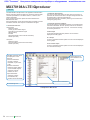
1
ООО "Техэнком"
Контрольно-измерительные приборы и оборудование
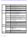
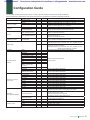
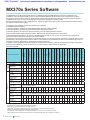
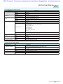
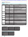
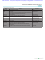
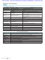
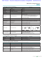
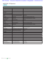
Function
Marker output
Baseband
reference
clock signal
Number of ports
Connector
Internal clock signal
External clock input signal
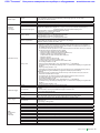
Memory capacity
Number of opened files
Waveform memory
Memory mode
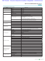
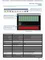
Function
Start/Frame trigger
Input connector
Start trigger
Frame trigger
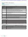
Function
Pattern trigger
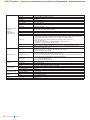
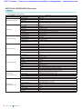
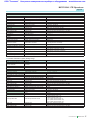
BER
Measurement
function
(Standard)
Input connector
Function
Input connector
Input signal
Input level
Input threshold level
Input bit rate
Measurable patterns
Measurable BER
Measurable time
Mode
Display
Measurable bit count
Auto Resync function
www.tehencom.com
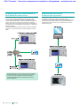
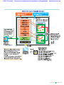
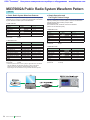
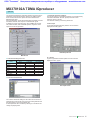
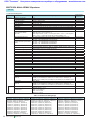
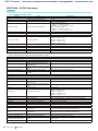
When a signal is allotted to a marker signal bit at waveform generation, up to three signals, such as
pulse modulation signal (for internal modulation), frame timing signal, etc., can be output.
The polarity can also be reversed.
3 ports
TTL, BNC-J (rear panel, AUX Input/Output Connector 1/2/3)
Range: 20 kHz to 160 MHz, Resolution: 0.001 Hz
Input frequency range: 20 kHz to 40 MHz
Divide and multiply functions: Signal of 1, 2, 4, 8, 16, 1/2, 1/4, 1/8, 1/16 times of input frequency
generated internally, and used as DAC sampling clock
Connector: BNC-J (rear panel, Baseband Reference Clock)
Input level:≥0.7 V (p-p)/50 Ω (AC coupled)
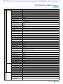
Waveform memories. A and B.
128 Msamples/channel × 2, 256 Msamples/channel Max.
With ARB Memory Upgrade 512 Msample option
256 Msamples/channel × 2, 512 Msamples/channel Max.
Up to 4096 waveform patterns opened per waveform memory (A/B)
100 packages per waveform memory, 100 patterns in one package.
Minimum number of samples per pattern: 100
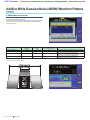
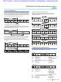
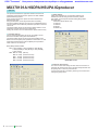
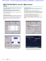
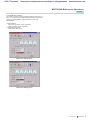
Defined Mode
Selection of a single waveform pattern to be used in either waveform memory A or B, selection of
waveform patterns using a combination file that defines addition of multiple waveform patterns, and
the addition level ratio can be set in this mode.
If a combination file that specifies two or more waveform patterns in waveform memory A is selected,
the following sequence operations become enabled.
• Selection of pattern switching mode (Auto/Manual)
• Selection of pattern switching point (Frame end/Pattern end)
• Switching of pattern by an external trigger signal
(enabled when the pattern switching mode is Manual)
• Restart of sequence
• Maximum number of elements: 200
• Minimum number of points per pattern: 1000
Level ratio setting range: Two-signal level ratio <80 dB or OFF
Level setting resolution: 0.01 dB
Frequency offset variable width: ± (0.8 × Sampling Clock × 2n – Bandwidth)/2
(n: Maximum integer that satisfying Sampling Clock × 2n ≤80 MHz when sampling clock greater than
20 MHz.)
Frequency setting resolution: 1 Hz
In this mode, two waveform memories can be connected for use as a 256 Msamples long memory
(512 Msamples long when ARB Memory Upgrade 512 Msample option installed).
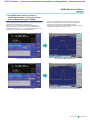
Edit Mode
One waveform each is selected from waveform memory A and waveform memory B, these two
waveforms are added and then output.
Two signal levels, the waveform memory B start offset and frequency offset, can be set.
Level ratio setting range: Two-signal level ratio <80 dB or OFF
Level setting resolution: 0.01 dB
Frequency offset variable width: ± (0.8 × Sampling Clock × 2n – Bandwidth)/2
(n: Maximum integer that satisfying Sampling Clock × 2n ≤80 MHz when sampling clock greater than
20 MHz.)
Frequency setting resolution: 1 Hz
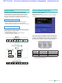
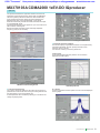
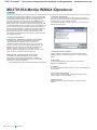
Switchable between continuous output and burst output.
Functional change: Connector shared by Start trigger and Frame trigger; switched depending on
situation
Connector: BNC-J (Front panel, Start/Frame Trigger), Input level: TTL,
Logic: Polarity Rise/Fall selected.
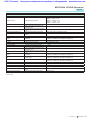
Starts waveform output
Searches for burst timing at burst output
Burst length data output and timing of frame trigger and waits for next frame trigger
When using the sequence mode, the pattern trigger will force a pattern switch.
Connector: Front panel, Pattern Trigger, BNC-J connector
Input level: TTL
Logic: Rising or falling polarity
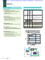
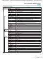
BER Measurement of demodulated data sequence
TTL, BNC-J (rear panel, BER Input)
Data, Clock, Enable (Polarity reversal supported.)
TTL
Matches threshold (0.8 to 2.4 V) of TTL
1 kbps to 20 Mbps
PN 9, 11, 15, 20, 23, ALL0, ALL1, ALT (alternating 0 and 1)
0 to 1% (Reference value; changes with system conditions and data rate)
≤359999.0 sec
Single, Endless, Continuous.
BitError, SyncLoss, ClockError, EnableError, Error Rate, Error Count
1000 to 4294967295 (232 – 1) bit
Switched between enable/disable
Product Brochure l
MG3700A
21