1
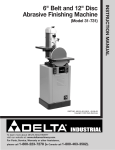
(Model 31-735)
PART NO. 913180 - 10-13-03
Copyright © 2003 Delta Machinery
To learn more about DELTA MACHINERY
visit our website at: www.deltamachinery.com.
For Parts, Service, Warranty or other Assistance,
please call
1-800-223-7278 (In Canada call 1-800-463-3582).
INSTRUCTION MANUAL
6" Belt and 12" Disc
Abrasive Finishing Machine
SAFETY GUIDELINES - DEFINITIONS
This manual contains information that is important for you to know and understand. This information relates to protecting YOUR SAFETY and PREVENTING EQUIPMENT PROBLEMS. To help you recognize this information, we use the
symbols to the right. Please read the manual and pay attention to these sections.
Indicates an imminently hazardous situation which, if not avoided, will result in death or serious injury.
Indicates a potentially hazardous situation which, if not avoided, could result in death or serious injury.
Indicates a potentially hazardous situation which, if not avoided, may result in minor or moderate injury.
Used without the safety alert symbol indicates potentially hazardous situation which, if not avoided, may
result in property damage.
SOME DUST CREATED BY POWER SANDING, SAWING, GRINDING, DRILLING, AND OTHER
CONSTRUCTION ACTIVITIES contains chemicals known to cause cancer, birth defects or other reproductive harm.
Some examples of these chemicals are:
· lead from lead-based paints,
· crystalline silica from bricks and cement and other masonry products, and
· arsenic and chromium from chemically-treated lumber.
Your risk from these exposures varies, depending on how often you do this type of work. To reduce your exposure to
these chemicals: work in a well ventilated area, and work with approved safety equipment, always wear MSHA/NIOSH
approved, properly fitting face mask or respirator when using such tools.
GENERAL SAFETY RULES
READ AND UNDERSTAND ALL WARNINGS AND OPERATING INSTRUCTIONS BEFORE
USING THIS EQUIPMENT. Failure to follow all instructions listed below, may result in electric shock,
fire, and/or serious personal injury or property damage.
IMPORTANT SAFETY INSTRUCTIONS
Woodworking can be dangerous if safe and proper operating procedures are not followed. As with all machinery, there
are certain hazards involved with the operation of the product. Using the machine with respect and caution will
considerably lessen the possibility of personal injury. However, if normal safety precautions are overlooked or ignored,
personal injury to the operator may result. Safety equipment such as guards, push sticks, hold-downs, featherboards,
goggles, dust masks and hearing protection can reduce your potential for injury. But even the best guard won’t make
up for poor judgment, carelessness or inattention. Always use common sense and exercise caution in the workshop.
If a procedure feels dangerous, don’t try it. Figure out an alternative procedure that feels safer. REMEMBER: Your
personal safety is your responsibility. For additional information please visit our website www.deltamachinery.com.
This machine was designed for certain applications only. Delta Machinery strongly recommends that this
machine not be modified and/or used for any application other than that for which it was designed. If you have any
questions relative to a particular application, DO NOT use the machine until you have first contacted Delta to determine
if it can or should be performed on the product.
Technical Service Manager
Delta Machinery
4825 Highway 45 North
Jackson, TN 38305
(IN CANADA: 505 SOUTHGATE DRIVE, GUELPH, ONTARIO N1H 6M7)
2
FAILURE TO FOLLOW THESE RULES MAY RESULT IN SERIOUS PERSONAL INJURY.
1.
2.
3.
4.
5.
6.
7.
8.
9.
10.
11.
12.
13.
FOR YOUR OWN SAFETY, READ THE INSTRUCTION MANUAL BEFORE OPERATING THE
MACHINE. Learning the machine’s application,
limitations, and specific hazards will greatly
minimize the possibility of accidents and injury.
USE CERTIFIED SAFETY EQUIPMENT. Eye
protection should comply with ANSI Z87.1
standards, hearing protection should comply with
ANSI S3.19 standards, and dust mask protection
should comply with MSHA/NIOSH certified
respirator standards. Splinters, air-borne debris,
and dust can cause irritation, injury, and/or illness.
DRESS PROPERLY. Do not wear tie, gloves, or
loose clothing. Remove watch, rings, and other
jewelry. Roll up your sleeves. Clothing or jewelry
caught in moving parts can cause injury.
DO NOT USE THE MACHINE IN A DANGEROUS
ENVIRONMENT. The use of power tools in damp
or wet locations or in rain can cause shock or
electrocution. Keep your work area well-lit to
prevent tripping or placing arms, hands, and
fingers in danger.
MAINTAIN ALL TOOLS AND MACHINES IN PEAK
CONDITION. Keep tools sharp and clean for best and
safest performance. Follow instructions for lubricating
and changing accessories. Poorly maintained tools and
machines can further damage the tool or machine and/or
cause injury.
CHECK FOR DAMAGED PARTS. Before using the
machine, check for any damaged parts. Check for
alignment of moving parts, binding of moving
parts, breakage of parts, and any other conditions
that may affect its operation. A guard or any other
part that is damaged should be properly repaired
or replaced. Damaged parts can cause further
damage to the machine and/or injury.
KEEP THE WORK AREA CLEAN. Cluttered areas and
benches invite accidents.
KEEP CHILDREN AND VISITORS AWAY. Your shop is
a potentially dangerous environment. Children and visitors
can be injured.
REDUCE THE RISK OF UNINTENTIONAL STARTING.
Make sure that the switch is in the “OFF” position
before plugging in the power cord. In the event of
a power failure, move the switch to the “OFF”
position. An accidental start-up can cause injury.
USE THE GUARDS. Check to see that all guards
are in place, secured, and working correctly to
prevent injury.
REMOVE ADJUSTING KEYS AND WRENCHES
BEFORE STARTING THE MACHINE. Tools, scrap
pieces, and other debris can be thrown at high
speed, causing injury.
USE THE RIGHT MACHINE. Don’t force a
machine or an attachment to do a job for which it
was not designed. Damage to the machine and/or
injury may result.
USE RECOMMENDED ACCESSORIES. The use
14.
15.
16.
17.
18.
19.
20.
21.
22.
23.
24.
3
of accessories and attachments not recommended by Delta may cause damage to the
machine or injury to the user.
USE THE PROPER EXTENSION CORD. Make
sure your extension cord is in good condition.
When using an extension cord, be sure to use one
heavy enough to carry the current your product will
draw. An undersized cord will cause a drop in line
voltage, resulting in loss of power and overheating.
See the Extension Cord Chart for the correct size
depending on the cord length and nameplate
ampere rating. If in doubt, use the next heavier
gauge. The smaller the gauge number, the heavier
the cord.
SECURE THE WORKPIECE. Use clamps or a vise to
hold the workpiece when practical. Loss of control
of a workpiece can cause injury.
FEED THE WORKPIECE AGAINST THE DIRECTION
OF THE ROTATION OF THE BLADE, CUTTER, OR
ABRASIVE SURFACE. Feeding it from the other
direction will cause the workpiece to be thrown out
at high speed.
DON’T FORCE THE WORKPIECE ON THE
MACHINE. Damage to the machine and/or injury
may result.
DON’T OVERREACH. Loss of balance can make
you fall into a working machine, causing injury.
NEVER STAND ON THE MACHINE. Injury could occur if
the tool tips, or if you accidentally contact the cutting tool.
NEVER LEAVE THE MACHINE RUNNING UNATTENDED. TURN THE POWER OFF. Don’t leave the machine
until it comes to a complete stop. A child or visitor could
be injured.
TURN THE MACHINE “OFF”, AND DISCONNECT THE
MACHINE FROM THE POWER SOURCE before
installing or removing accessories, before adjusting
or changing set-ups, or when making repairs. An
accidental start-up can cause injury.
MAKE YOUR WORKSHOP CHILDPROOF WITH
PADLOCKS, MASTER SWITCHES, OR BY
REMOVING STARTER KEYS. The accidental
start-up of a machine by a child or visitor could
cause injury.
STAY ALERT, WATCH WHAT YOU ARE DOING,
AND USE COMMON SENSE. DO NOT USE THE
MACHINE WHEN YOU ARE TIRED OR UNDER
THE INFLUENCE OF DRUGS, ALCOHOL, OR
MEDICATION. A moment of inattention while
operating power tools may result in injury.
THE DUST GENERATED by certain woods and
wood products can be injurious to your health.
Always operate machinery in well-ventilated areas,
and provide for proper dust removal. Use wood
dust collection systems whenever possible.
ADDITIONAL SAFETY RULES
FOR ABRASIVE FINISHING MACHINES
FAILURE TO FOLLOW THESE RULES MAY RESULT IN SERIOUS PERSONAL INJURY.
1.
DO NOT OPERATE THIS MACHINE until it is
completely assembled and installed according to
the instructions. A machine incorrectly assembled
can cause serious injury.
2. OBTAIN ADVICE from your supervisor, instructor, or
another qualified person if you are not thoroughly
familiar with the operation of this machine.
Knowledge is safety.
3. FOLLOW ALL WIRING CODES and recommended
electrical connections to prevent shock or electrocution.
4. NEVER TURN THE MACHINE “ON” before
clearing the table/work area of all objects (tools,
scraps of wood, etc.). Flying debris is dangerous.
5. NEVER TURN THE MACHINE “ON” with the workpiece contacting the abrasive surface. Kickback can
occur.
6. THIS MACHINE CAN BE USED FOR
PROCESSING WOOD OR METAL PRODUCTS:
However, combining both wood dust and metal
filings can create a fire hazard. In addition
combining aluminum dust with metal dust can
create a fire hazard. Before processing different
types of materials, such as wood, steel, and
aluminum, clean machine and dust collector to
avoid a fire hazard. DO NOT sand or polish
magnesium. It could catch on fire.
7. COVER THE POWER TAKE-OFF SHAFT when not
using accessories. Unguarded rotating shafts can
create an entanglement hazard which can result in
injury.
8. USE A DUST COLLECTION SYSTEM. Some types
of materials are known to cause disease or other
health problems.
9. CLEAN THE MACHINE and dust collector thoroughly
when processing different types of workpieces
(wood, steel, or aluminum). Combining wood and
metal dust can create an explosion or fire hazard.
DO NOT SAND OR POLISH MAGNESIUM. Fire will
result.
10. PREVENT THE WORKPIECE from contacting the
sanding belt before starting the tool. Loss of control
of the workpiece is dangerous.
11. AVOID AWKWARD OPERATIONS AND HAND
POSITIONS. A sudden slip could cause a hand to
move into the abrasive disc or belt.
12. MAINTAIN A MAXIMUM CLEARANCE OF 1/16" between the table and the abrasive disc. The
workpiece could be drawn into the space between
the abrasive disc and the table.
13. SUPPORT THE WORKPIECE firmly with a miter
gauge, backstop, or work table when sanding with a
belt. Hold the workpiece firmly. Loss of control of the
workpiece can result in injury.
14. AVOID KICKBACK by sanding in accordance with
the directional arrows. Feed the workpiece against
the downward rotation side of the disc or the
forward rotation of the belt. Loss of control of the
workpiece can result in injury.
15. DO NOT SAND very small or very thin workpieces
that cannot be safely controlled. Loss of control of
the workpiece can result in injury.
16. PROPERLY SUPPORT LONG OR WIDE WORKPIECES. Loss of control of the workpiece is dangerous.
17. NEVER PERFORM LAYOUT, ASSEMBLY, OR SET-UP
WORK on the table/work area when the machine is
running. A sudden slip could cause a hand to move
into the abrasive surface. Severe injury can result.
18. TURN THE MACHINE “OFF”, disconnect the
machine from the power source, and clean the
table/work area before leaving the machine. LOCK
THE SWITCH IN THE “OFF” POSITION to prevent
unauthorized use. Someone else might accidentally
start the machine and cause injury to themselves.
19. DO NOT insert fingers or foreign objects into the
dust intake port. Keep hair, loose clothing, fingers,
and all body parts away from openings and moving
parts of the dust collector.
20. DO NOT use with any opening blocked; keep
openings free of dust, lint, hair, and anything that
may reduce air flow.
21. NEVER operate the dust collector without the dust
collection bag in place and properly secured.
22. ALWAYS use intake caps to cover unused dust
ports when the dust collector is not in use.
23. PERIODICALLY INSPECT dust bag for any cuts,
rips or tears. NEVER operate the dust collector with
a damaged bag or vacuum hose.
24. ADDITIONAL INFORMATION regarding the safe
and proper operation of power tools (i.e. a safety
video) is available from the Power Tool Institute,
1300 Sumner Avenue, Cleveland, OH 44115-2851
(www.powertoolinstitute.com). Information is also
available from the National Safety Council, 1121
Spring Lake Drive, Itasca, IL 60143-3201. Please
refer to the American National Standards Institute
ANSI 01.1 Safety Requirements for Woodworking
Machines and the U.S. Department of Labor OSHA
1910.213 Regulations.
SAVE THESE INSTRUCTIONS.
Refer to them often and use them to instruct others.
4
POWER CONNECTIONS
A separate electrical circuit should be used for your machines. This circuit should not be less than #12 wire and should
be protected with a 20 Amp time lag fuse. If an extension cord is used, use only 3-wire extension cords which have 3prong grounding type plugs and matching receptacle which will accept the machine’s plug. Before connecting the
machine to the power line, make sure the switch is in the “OFF” position and be sure that the electric current is of the
same characteristics as indicated on the machine. All line connections should make good contact. Running on low
voltage will damage the machine.
DO NOT EXPOSE THE MACHINE TO RAIN OR OPERATE THE MACHINE IN DAMP LOCATIONS.
MOTOR SPECIFICATIONS
Your machine is wired for 240, or 200/460 volt, 60 HZ alternating current. Before connecting the machine to the
power source, make sure the switch is in the “OFF” position.
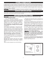
GROUNDING INSTRUCTIONS
THIS MACHINE MUST BE GROUNDED WHILE IN USE TO PROTECT THE OPERATOR FROM
ELECTRIC SHOCK.
2. Grounded, cord-connected machines intended for use
1. All grounded, cord-connected machines:
on a supply circuit having a nominal rating between 150
In the event of a malfunction or breakdown, grounding
- 250 volts, inclusive:
provides a path of least resistance for electric current to
reduce the risk of electric shock. This machine is
If the machine is intended for use on a circuit that has an
equipped with an electric cord having an equipmentoutlet that looks like the one illustrated in Fig. C, the
grounding conductor and a grounding plug. The plug
machine will have a grounding plug that looks like the
must be plugged into a matching outlet that is properly
plug illustrated in Fig. C. Make sure the machine is
installed and grounded in accordance with all local codes
connected to an outlet having the same configuration as
and ordinances.
the plug. No adapter is available or should be used with
this machine. If the machine must be re-connected for
Do not modify the plug provided - if it will not fit the outlet,
use on a different type of electric circuit, the rehave the proper outlet installed by a qualified electrician.
connection should be made by qualified service
Improper connection of the equipment-grounding
personnel; and after re-connection, the machine should
conductor can result in risk of electric shock. The
comply with all local codes and ordinances.
conductor with insulation having an outer surface that is
IN ALL CASES, MAKE CERTAIN
THE
green with or without yellow stripes is the equipmentR E C E P TA C L E I N Q U E S T I O N I S P R O P E R LY
grounding conductor. If repair or replacement of the
electric cord or plug is necessary, do not connect the
G R O U N D E D . I F Y O U A R E N O T S U R E H AV E A
equipment-grounding conductor to a live terminal.
QUALIFIED ELECTRICIAN CHECK THE RECEPTACLE.
Check with a qualified electrician or service personnel if
3. Permanently connected machines:
t h e g ro u n d i n g i n s t r u c t i o n s a re n o t c o m p l e t e l y
If the machine is intended to be permanently connected,
understood, or if in doubt as to whether the machine is
the machine should be connected to a grounded metal
properly grounded.
permanent wiring system, or to a system having an
Use only 3-wire extension cords that have 3-prong
equipment-grounding conductor.
grounding type plugs and matching 3-conductor
receptacles that accept the machine’s plug, as shown in
Fig. A.
Repair or replace damaged or worn cord immediately.
CURRENT
CARRYING
PRONGS
GROUNDED OUTLET BOX
GROUNDING BLADE
IS LONGEST OF THE 3 BLADES
Fig. A
5
THREE PHASE OPERATION
If the motor on your machine is wired for 200V, 230V, or 460V, three phase, the necessary wiring from the starter to the
power should be completed by a qualified electrician.
EXTENSION CORDS
Use proper extension cords. Make sure your extension cord is in good condition and is a 3-wire
extension cord which has a 3-prong grounding type plug and matching receptacle which will accept the machine’s
plug. When using an extension cord, be sure to use one heavy enough to carry the current of the machine. An
undersized cord will cause a drop in line voltage, resulting in loss of power and overheating. Fig. D, shows the correct
gauge to use depending on the cord length. If in doubt, use the next heavier gauge. The smaller the gauge number,
the heavier the cord.
MINIMUM GAUGE EXTENSION CORD
RECOMMENDED SIZES FOR USE WITH STATIONARY ELECTRIC MACHINES
Ampere
Rating
Volts
Total Length
of Cord in Feet
Gauge of
Extension Cord
0-6
0-6
0-6
0-6
240
240
240
240
up to 50
50-100
100-200
200-300
18 AWG
16 AWG
16 AWG
14 AWG
6-10
6-10
6-10
6-10
240
240
240
240
up to 50
50-100
100-200
200-300
18 AWG
16 AWG
14 AWG
12 AWG
10-12
10-12
10-12
10-12
240
240
240
240
up to 50
50-100
100-200
200-300
16 AWG
16 AWG
14 AWG
12 AWG
12-16
12-16
12-16
240
240
240
up to 50
50-100
14 AWG
12 AWG
GREATER THAN 100 FEET NOT RECOMMENDED
Fig. D
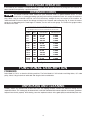
FUNCTIONAL DESCRIPTION
FOREWORD
Delta Model 31-735 is an abrasive finishing machine. The Delta Model 31-735 includes two tilting tables, 4½" arbor
pulley, V-belt, 100-grit aluminum oxide belt and 80-grit aluminum oxide disc.
UNPACKING AND CLEANING
Carefully unpack the machine and all loose items from the shipping container. Remove the protective coating from all
unpainted surfaces. This coating may be removed with a soft cloth moistened with kerosene (do not use acetone, gasoline or
lacquer thinner for this purpose). After cleaning, cover the unpainted surfaces with a good quality household floor paste wax.
6
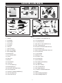
CARTON CONTENTS
8
2
9
5
1
3
4
11
6
7
10
25
24
29
13
12
36
35
15
32
33
17
16
34
18
19
40
20
21
22
41
39
23
38
43
44
42
Fig. 1
1. Cabinet
24. 1/4-20x5/8" Flat Head Screw (4)
2. Dust Baffle
25. 1/4" Flat Washer (4)
3. Bag Hanger
26. 1/4-20 Hex Nut (4)
4. Dust Chute
27. 5/16-18x1/2" Hex Head Screw (4)
5. Dust Bag
28. 5/16" Lockwasher (4)
6. Hose (2)
29. #10-32x3/4" Button Head Screw (4)
7. Hose Clamp (5)
30. #10 Flat Washer (4)
8. Belt / Disc Sander
31. M4-0.7x12mm Sheet Metal Screw (4)
9. Belt Sanding Table
32. 3/8-16 Lock Nut
10. Abrasive Disc
33. 1-3/16" Spring
11. Disc Sanding Table
34. Ratchet Lever
12. Caster
35. 3/8-16x3½" Stud
13. Foot Lever
36. 3/8-16 Hex Nut
14. Bracket
37. 3/8 Flat Washer
15. Pivot Bracket
38. Disc Table Lock Handle (2)
16. 1/2x4" Pin
39. 1/2" Spring (2)
17. 1/2" Flat Washer (2)
40. 7/16-18x3" Stud (2)
18. Retaining Ring (2)
41. 7/16" Flat Washer (2)
19. 5/16-18x4" Hex Head Screw
42. Disc Table Clamp (2)
20. 5/16-18 Lock Nut
43. 1/4-20x1/4" Round Head Screw
21. 3/8-16x1" Carriage Head Bolt (3)
44. Pointer
22. 3/8" Flat Washer (3)
45. Circle Sanding Stop Block
23. 3/8-16 Hex Nut (3)
46. Circle Sanding Guide Pin
7
46
30
31
14
45
26
28
27
37
ASSEMBLY
FOR YOUR OWN SAFETY, DO NOT CONNECT THE MACHINE TO THE POWER SOURCE UNTIL
THE MACHINE IS COMPLETELY ASSEMBLED AND YOU READ AND UNDERSTAND THE ENTIRE
INSTRUCTION MANUAL.
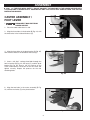
CASTER ASSEMBLY /
FOOT LEVER
1.
DISCONNECT MACHINE FROM
POWER SOURCE.
B
2. Place the motor cabinet on its side.
3. Align the three holes in the bracket (B) Fig. 2A, with
the three holes in the inside of the base (C).
C
Fig. 2A
4. Align the three holes in the pivot bracket (D) Fig. 2B,
with the three holes in the outside of the base (C).
D
5. Insert a 3/8-16x1" carriage head bolt through the
hole in bracket (B) Fig. 2A, the base (C), and the pivot
bracket (D) Fig. 2B. Place a 3/8" flat washer on the
screw, and thread a 3/8-16 hex nut on the screw and
tighten securely. Repeat this process for the two
remaining holes.
C
Fig. 2B
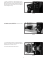
6. Align the two holes in the caster assembly (E) Fig.
2C, with the two holes (F) in the pivot bracket.
F
E
Fig. 2C
8
7. Insert a 5/16-18x4" hex head screw (G) Fig. 2D,
through the hole (F) Fig. 2C, in the pivot bracket, the two
holes (E) in the caster assembly and the other hole (F) in
the pivot bracket. Thread a 5/16-18 lock nut onto the
screw and tighten securely.
G
Fig. 2D
8. Align the two holes (H) Fig 2E, in the foot lever, with
the two holes (J) in the pivot bracket.
J
H
Fig. 2E
9. Assemble foot lever (N) Fig. 2F, to pivot bracket (O),
using 1/2"x4" pin (M), two 1/2" flat washers (K), and two
retaining rings (P) as shown in Fig. 2F.
N
P
M
O
10. Stand the motor cabinet up on its base.
K
P
Fig. 2F
9
DUST BAFFLE
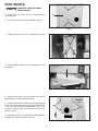
1.
DISCONNECT MACHINE FROM
POWER SOURCE.
A
2. Remove the two screws (A) Fig. 3, and loosen the
two screws (B).
C
3. Remove the back cover of the cabinet (C) Fig. 3.
B
Fig. 3
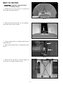
4. Loosen the four nuts (D) Fig. 4, and lower the motor.
D
Fig. 4
5. Insert the dust baffle (F) Fig. 5, through the front of
the cabinet.
F
Fig. 5
6. Align the four slots in the dust baffle with the four
holes (G) Fig. 6, in the top of the cabinet.
CABINET
TOP
7. Insert a 1/4-20x5/8" flat head screw through hole (G)
Fig. 6 in the top of the cabinet and the dust baffle. Place
a 1/4" flat washer onto the screw, thread a 1/4-20 hex
nut onto the screw, from the inside of the cabinet and
tighten securely.
G
G
8. Repeat this process for the three remaining holes in
the top of the cabinet and the dust baffle.
Fig. 6
10
BELT / DISC SANDER
TO CABINET
THE BELT / DISC SANDER IS HEAVY,
USE TWO OR MORE PEOPLE WHEN
PLACING THE BELT / DISC SANDER
ON TOP OF THE CABINET.
1.
C
C
A
DISCONNECT MACHINE FROM
POWER SOURCE.
2. Place the Belt/Disc sander on top of the cabinet.
NOTE: MAKE SURE THE DRIVE BELT ON THE
DISC/BELT SANDER IS INSERTED THROUGH THE
HOLE (A) FIG. 7.
B
B
Fig. 7
3. Place a 5/16" lock washer onto a 5/16-18x½" hex
head screw. Insert the screw, from the inside of the
cabinet, through the hole (B) Fig. 7, and thread into the
Belt/Disc sander. Tighten the screw securely.
4. Repeat this process for the three remaining holes (B)
Fig. 7, in the cabinet and the Belt/Disc sander.
5. Place a #10 washer onto a #10-32x3/4" button head
screw. Insert the screw, from the inside of the cabinet,
through the slot (C) Fig. 7, in the dust baffle, and cabinet
and thread the screw into the Belt/Disc sander. Tighten
the screw securely.
6. Repeat this process for the three remaining slots in
the dust baffle, cabinet, and the Belt/Disc sander.
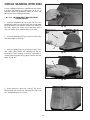
Fig. 8
7. Fig. 8 shows the Belt/Disc sander attached to the
cabinet.
DUST COLLECTOR
INTAKE HOSE
B
A
A
1.
DISCONNECT MACHINE FROM
POWER SOURCE.
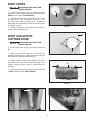
2. Place a hose clamp (A) Fig. 9, on each end of hose
(B).
3. Slide one end of hose (B) Fig. 10, over the hose port
(C) on the dust baffle, from the inside of the cabinet.
Tighten the hose clamp around the hose port on the
dust baffle.
Fig. 9
4. Slide the other end of the hose over the fan intake
port (F) Fig. 11, from the inside of the cabinet. Tighten
the hose clamp around the fan intake port.
C
B
F
Fig. 10
Fig. 11
11
BELT TO MOTOR
1.
DISCONNECT MACHINE FROM
POWER SOURCE.
A
2. Remove the two screws (A) Fig. 12, on top of the
disc sander and remove plate (B).
B
Fig. 12
3. Make sure that the belt (C) Fig. 13, is in the groove
of the pulley (D) on the disc sander.
D
C
Fig. 13
4. Lift up on motor (F) Fig. 14, and place belt (C) on the
motor pulley (G).
C
5. Slowly release motor (F) Fig. 14, to apply pressure to
belt (C).
G
F
Fig. 14
6. Make sure that the motor is level and tighten hex
nuts (H) Fig. 15, to hold the motor in place.
H
Fig. 15
12
DUST CHUTE
1.
DISCONNECT MACHINE FROM
POWER SOURCE.
B
2. Insert the dust chute (A) Fig. 16, through the inside
hole of the cabinet back panel (B) that was removed in
STEP 3 of the section “DUST BAFFLE”.
A
3. Align the four holes in the dust chute (A) Fig. 17, with
the four holes in the back panel (B). Insert a M40.7x12mm sheet metal screw (C) Fig. 17, through the
back panel (B), and thread the screw into the dust chute
and tighten securely.
Fig. 16
4. Repeat this process for the three remaining holes in
the back panel and dust chute.
B
DUST COLLECTOR
OUTTAKE HOSE
1.
C
DISCONNECT MACHINE FROM
POWER SOURCE.
C
2. Place a hose clamp (A) Fig. 18, on each end of hose
(B).
A
3. Slide one end of hose (B) Fig. 19, over the dust
collector outtake port (C). Tighten the hose clamp (A)
around the dust collector outtake port (C).
Fig. 17
4. Slide the other end of the hose (B) Fig. 20, over the
dust chute (D), on the inside of the back panel of the
cabinet. Tighten the hose clamp (A) around the dust
chute (D).
B
A
A
5. Replace the back panel of cabinet that was removed
in STEP 3 of the section “DUST BAFFLE”.
Fig. 18
A
C
B
D
B
A
Fig. 19
Fig. 20
13
BELT SANDER TABLE
1.
E
DISCONNECT MACHINE FROM
POWER SOURCE.
A
B
C
2. Thread a 3/8-16 lock nut (A) Fig. 21, onto a 3/816x3½" stud (B).
NOTE: THREAD LOCK NUT FAR ENOUGH SO THAT
THE NUT (A) FIG. 12 IS FLUSH OR SLIGHTLY BELOW
THE THREADS ON THE STUD.
F
D
3. Place a 1-3/16" spring (C) Fig. 21, onto stud (B).
Fig. 21
4. Insert sanding ratchet lever (D) Fig. 21, onto stud (B).
5. Thread a 3/8-16 hex nut (E) Fig. 21, onto stud (B).
6. Place a 3/8" flat washer (F) Fig. 21, onto stud (B).
K
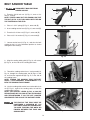
7. Loosen ratchet lever (H) Fig. 22, and raise the belt
sander so that it is in the horizontal position as shown
and tighten lock knob (H).
H
Fig. 22
8. Align the sanding table guide (J) Fig. 23, with cutout
(K) Fig. 23, on the side of the sanding belt frame.
J
K
9. Thread the sanding ratchet lever / stud assembly (L)
Fig. 24, through the sanding table slot (N) Figs. 23 and
24, and into the tapped hole (M) Fig. 23, in the side of
the sanding frame.
NOTE: THREAD THE SANDING TABLE RATCHET
LEVER / STUD ASSEMBLY APPROXIMATELY 1/2"
INTO THE SANDING TABLE FRAME.
M
N
Fig. 23
10. Use the sanding table ratchet lever to thread the hex
nut (E) Fig 21, against the sanding table, to hold the
sanding table in place.
NOTE: THE RATCHET LEVER (A) FIG. 24 CAN BE
REPOSITIONED BY PULLING OUT ON THE HANDLE
AND REPOSITIONING IT ON THE NUT LOCATED
UNDERNEATH THE HUB OF THE RATCHET LEVER.
THE EDGE OF THE TABLE MUST BE
POSITIONED A MAXIMUM OF 1/16
INCH AWAY FROM THE SANDING BELT
TO AVOID TRAPPING THE WORK OR
FINGERS BETWEEN THE TABLE AND
SANDING BELT.
N
L
Fig. 24
14
DISC SANDER TABLE
AND POINTER
1.
A
DISCONNECT MACHINE FROM
POWER SOURCE.
A
2. Thread the 7/16x3" disc sanding table studs (A) Fig.
25, into the side of the disc sander.
3. Place the disc sander table clamp (B) onto stud (A)
as shown in Fig. 26. Repeat this process for the
remaining stud (A) Fig. 25, on the other side of the disc
sander.
Fig. 25
4. Align the table lock rail (C) Fig. 27, on the disc
sander table, with the grooves in the table clamps (B).
5. Place a 7/16" flat washer (C) Fig. 28, onto each stud,
then a 1/2" spring (D), thread the disc table lock handle
(E) onto right side stud and tighten securely to hold the
disc sander table in place.
THE EDGE OF THE TABLE MUST BE
POSITIONED THE PROPER DISTANCE
AWAY FROM THE SANDING DISC TO
AVOID TRAPPING THE WORK OR
FINGERS BETWEEN THE TABLE AND
SANDING DISC. PLEASE SEE THE
SECTION “ABRASIVE DISC”.
B
A
Fig. 26
6. Align the hole in the pointer (A) Fig. 29, with the
tapped hole (D) in the the left side table clamp.
C
7. Insert a 1/4-20x1/4" round head screw (B) Fig. 29,
through the hole in the pointer and thread into the table
clamp and tighten securely.
8. Thread the disc table lock handle (E) Fig. 28 onto left
side stud and tighten securely to hold the disc sander
table in place.
B
Fig. 27
A
D
C
B
E
Fig. 28
D
Fig. 29
15
ABRASIVE DISC
A
1.
DISCONNECT MACHINE FROM
POWER SOURCE.
2. Make certain the disc assembly (A) Fig. 30, is clean,
dry, and free of any oil or grease.
C
3. Separate and fold back approximately half of the
adhesive backing from the abrasive disc (C) Fig. 30,
supplied with the machine. Insert the abrasive disc (C),
with the backing, between the table, and disc assembly
(A), as shown in Fig. 30, and press the top half of the
adhesive disc (C), in position.
Fig. 30
4. Manually turn the disc assembly (A) Fig. 31, and
remove the paper backing from the abrasive disc (C),
and firmly press the abrasive disc onto disc assembly
(A).
MAKE CERTAIN THE ABRASIVE DISC
(C), IS SECURELY IN POSITION
BEFORE APPLYING POWER TO THE
MACHINE.
THE EDGE OF THE TABLE MUST BE
POSITIONED A MAXIMUM OF 1/16
INCH AWAY FROM THE SANDING DISC
TO AVOID TRAPPING THE WORK OR
FINGERS BETWEEN THE TABLE AND
SANDING DISC.
A
C
Fig. 31
DUST COLLECTOR BAG
1.
DISCONNECT MACHINE FROM
POWER SOURCE.
2. Insert the dust collector bag hanger (A) Fig. 32 into
the two holes (B) in the top of the cabinet.
3. Place the end of the dust collector bag (C) Fig. 33,
over the dust collector hanger (A).
A
4. Place a hose clamp (D) Fig. 34, over the intake port
of the dust collector bag (C). Slide the intake port of the
dust collector bag over the dust chute (E) of the dust
collector. Tighten the hose clamp around the dust
collector intake port on the bag (C) and the dust chute
(E) of the dust collector.
NOTE: MAKE SURE TO REVIEW THE SECTION
“DUST PORT COVER” WHEN OPERATING THE
DUST COLLECTOR.
B
Fig. 32
C
E
A
C
D
Fig. 33
Fig. 34
16
OPERATING CONTROLS AND ADJUSTMENTS
STARTING AND STOPPING
THE ABRASIVE FINISHING
MACHINE
To start the machine, push “START” button (A) Fig. 35. To
stop the machine, push “STOP” button (B).
A
B
Fig. 35
LOCKING SWITCH
IN THE “OFF” POSITION
IMPORTANT: When the machine is not in use, the switch
should be locked in the OFF position using a padlock (C)
Fig. 36, with a 3/16" diameter shackle to prevent
unauthorized use.
C
ADJUSTING TENSION
AND TRACKING OF
SANDING BELT
Fig. 36
YOUR
MACHINE
IS
SHIPPED
WITHOUT BELT TENSION APPLIED TO THE
SANDING BELT. BEFORE OPERATING THE
MACHINE IT IS VERY IMPORTANT TO INSURE THAT
THE BELT IS TRACKING CORRECTLY AND IT IS
PROPERLY TENSIONED. PROCEED AS FOLLOWS:
1.
B
A
A
DISCONNECT MACHINE FROM
POWER SOURCE.
2. Loosen the two lock knobs (A) Fig. 37, and remove
the top cover (B).
Fig. 37
3. Turn the belt tension handle (C) Fig. 38, counterclockwise to increase belt tension. Correct tension is
determined by two things:
(1) The belt should be flat on the platen.
C
(2) The belt should be sufficiently tensioned to
prevent slipping on very heavy work. For ordinary work,
a tension just sufficient to take the curl out of the belt is
recommended.
Fig. 38
17
4. Rotate the belt by hand, and tighten or loosen
tracking knob (E) Fig. 39, until the belt is running true on
the pulleys.
5. Jog the machine on and off to confirm the belt is
tracking properly. If the belt is leading to one side or the
other, very gently turn the tracking knob (E) Fig. 39,
clockwise to move the belt toward the adjusting screw
and counterclockwise to move the belt away from the
adjusting screw while jogging the machine on and off.
E
6. A final adjustment can be made with the motor
running. THIS ADJUSTMENT IS USUALLY VERY
SLIGHT. After the belt is tracking properly, disconnect
the machine from the power source, and replace the top
cover that was removed in STEP 2.
Fig. 39
NOTE: After a long period of time, adjustments may
be necessary to maintain the tension and tracking of
the sanding belt. If the belt will not hold its tension,
tighten the set screw (G) Fig. 40. If the belt will not
hold its tracking, tighten the set screw (F) Fig. 40.
Make only small adjustments to these screws. Overtightening will lock the tension lever and/or the
tracking knob.
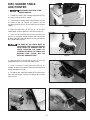
F
G
SANDING BELT TABLE 90
DEGREES TO BELT
1.
Fig. 40
DISCONNECT MACHINE FROM
POWER SOURCE.
A
2. Loosen the table tilting ratchet lever (A) Fig. 41,
rotate the stop (B) to the left, and rotate the table (C) Fig.
42 until the trunnion (D) Fig. 41 contacts the stop (B).
Tighten the lock handle (A). NOTE: The lock handle (A)
is spring-loaded and can be repositioned by pulling out
the handle, moving it, and letting it spring back into
position.
F
B
D
3. Place a square (E) Fig. 42 on the table against the
belt. See if the table is 90 degrees to the belt.
Fig. 41
4. To adjust, loosen the table tilting lock handle (A) Fig.
41. Turn the adjusting screw (F) in or out until table is 90
degrees to the belt.
5.
Tighten the lock handle (A) Fig. 41.
E
6. The adjusting screw (F) Fig. 41 ensures that the belt
table can rapidly return to the 90 degree position after
the table has been tilted.
7.
C
Adjust the pointer, if necessary.
8. The same procedure is followed when adjusting the
table to stop at the 45 degrees position.
Fig. 42
18
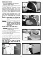
B
B
A
C
C
A
D
D
Fig. 43
Fig. 44
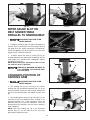
MITER GAUGE SLOT ON
BELT SANDER TABLE
PARALLEL TO SANDING BELT
1.
DISCONNECT MACHINE FROM
POWER SOURCE.
2. Position the table (A) (Figs. 43 and 44) 90 degrees to
the belt. Place a square (B) in the miter gauge slot with
the blade (C) of the square touching the sanding belt.
Check the opposite end of the belt to see if the miter
gauge slot (D) is parallel to the belt.
E
Fig. 45
3. To adjust, loosen the three (3) screws (E) Fig. 45,
located underneath the table. Move the table (A) until the
miter gauge slot is parallel to the sanding belt. Tighten
the three (3) screws (E).
NOTE: When making this adjustment, make sure that
the table lock lever is tightened.
C
A
E
MAINTAIN A MAXIMUM DISTANCE OF
1/16" BETWEEN THE SANDING BELT
AND THE TABLE.
CHANGING POSITION OF
SANDING ARM
1.
B
DISCONNECT MACHINE FROM
POWER SOURCE.
Fig. 46
2. The sanding arm (A) can be used in the vertical
position (Fig. 46), the horizontal position (Fig. 47), or any
angle in between. Loosen the lock lever (B), position the
arm (A) to the desired angle, and tighten the lock lever
(B).
E
C
D
3. The top idler pulley cover (C) Figs. 46 and 47 can be
removed to clear the workpiece when sanding in the
horizontal position. For a long workpiece, lower the
deflector plate (D) to clear the workpiece. Raise the
deflector plate (D) to deflect saw dust when sanding a
short workpiece.
NOTE: With the sanding arm (A) in the horizontal
position (Fig. 47), use the table (E) or the accessory
backstop to support the work.
B
A
Fig. 47
19
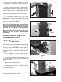
SANDING DISC TABLE 90
DEGREES TO DISC
1.
C
DISCONNECT MACHINE FROM
POWER SOURCE.
2. Loosen the two disc table lock handles, the left one
is shown at (A) Fig. 48, and move the table (B) until the
it contacts the table stop screw (C) on the left side of the
table. Tighten the lock handles.
A
3. Place a square (E) Fig. 49 on the table and against
the sanding disc. See if the table is 90 degrees to the
disc.
Fig. 48
4. To adjust, loosen the lock handles (A) Fig. 48, and
tighten or loosen the table stop screw (C) Fig. 48 until
the table is 90 degrees to the disc.
B
5.
Adjust sanding disc table pointer, if necessary
E
TILTING THE DISC
SANDER TABLE
1.
DISCONNECT MACHINE FROM
POWER SOURCE.
2. To tilt the table, loosen the disc table lock handles,
one of which is shown at (A) Fig. 48, and move the table
to the desired angle and tighten the lock handles.
Fig. 49
DISC TABLE MITER GAUGE
SLOT PARALLEL TO
SANDING DISC
1.
B
DISCONNECT MACHINE FROM
POWER SOURCE.
2. With the table (A) Fig. 50 positioned 90 degrees to
the disc, place a square (B) in the miter gauge slot with
the blade of the square touching the sanding disc.
A
3. Use a pencil to mark the disc where the square (B)
Fig. 50 contacts the disc, and measure the distance
from the disc to the miter gauge slot.
Fig. 50
4. Rotate the disc to the other end of the table. Use a
square to check the distance between the miter gauge
slot and the mark on the disc made in STEP 3. Make
sure that the distances are the same.
5. To adjust, loosen the four screws, on the table
trunnions, two of which are shown at (D) Fig. 51. Adjust
the table until the miter gauge slot is parallel to the disc.
Tighten the four screws (D).
NOTE: When making this adjustment, make sure
that the table lock handle is tightened.
D
MAINTAIN A MAXIMUM DISTANCE OF
1/16" BETWEEN THE SANDING DISC
AND THE TABLE.
Fig. 51
20
DUST PORT COVER
The abrasive finishing machine is equipped with a
manually operated dust port cover (A) Fig. 52, which
must be adjusted to suit the sanding operation.
1.
A
DISCONNECT MACHINE FROM
POWER SOURCE.
2. If you are sanding with the disc, push in on dust port
cover (A) Fig. 52.
Fig. 52
3. If you are sanding on the belt, pull dust port cover
(A) Fig. 53, outward.
A
Fig. 53
OPERATIONS
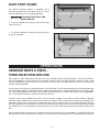
ABRASIVE BELTS & DISCS THEIR SELECTION AND USE
Delta supplies a wide range of belts and discs for use on your Belt and Disc Finishing Machine. These belts and discs
are recommended for a wide range of work on wood, metals, plastics and other materials. However, when a large
amount of production work of one kind is to be done, it is best to call in a coated abrasive specialist for specific belt
and disc recommendations.
A wide variety of materials may be processed on a dry belt or disc. But for professional quality or for production work
a low melting point grease should be used for cooler cutting, better finish, and for longer belt life. Even coarse belts
will "load" when grinding aluminum dry, and so a lubricant should always be used for this material. To a varying degree,
this is true of other non-ferrous metals like soft brass and zinc.
A grease stick is often applied to the belt or disc to prevent "loading" of the belt on softer materials especially
aluminum. When grinding steel or some kinds of plastic, the grease stick is often used to prevent over-heating of the
work piece. Many times a single belt is used for both stock removal and for finish, just by lubricating one half of the
belt with light grease for stock removal and the other side or half of the belt with a heavy grease for polishing to bring
out a good finish. This can be done only when the parts are very small and need not be moved across the face of the
belt.
When an abrasive belt smaller than 6" is desired, the 6" belt can be split. This can be done by turning the belt inside
out and with a knife or other sharp instrument cut a slot in the belt at the desired width. Then proceed to tear the belt.
21
ONLY TEAR THE BELT A FEW INCHES AT A TIME ONE WAY THEN REVERSE THE TEARING
ACTION. THIS METHOD WILL REDUCE THE TENDENCY OF THE BELT TO UNRAVEL.
For certain applications, a mist coolant attachment (not supplied by Delta) will be helpful. If the use of a mist coolant
causes the Abrasive Belt to slip on the lower drive pulley, this can be corrected by using a "tire" which can be
homemade by wrapping the pulley with a piece of coated abrasive belt. The grit is, of course, turned to the outside
and cement should be used sparingly to avoid lumps under the "tire."
SURFACING OR EDGE
SANDING WITH
SANDING BELT
When surfacing (see Fig. 54), or edge sanding (see Fig.
55), the sanding arm is in the horizontal position and the
table (A) Fig. 54 and Fig. 55, must always be used to
prevent the workpiece from being carried along the belt.
Always hold the workpiece firmly, keeping your fingers
away from the sanding belt. Always keep the end of the
workpiece against the table and move the workpiece
evenly across the sanding belt. Apply only enough
pressure to allow the sanding belt to remove material.
Use extra caution when sanding very thin pieces.
A
Fig. 54
THE EDGE OF THE TABLE MUST BE
POSITIONED A MAXIMUM OF 1/16
INCH AWAY FROM THE SANDING BELT
TO AVOID TRAPPING THE WORK OR
FINGERS BETWEEN THE TABLE AND
SANDING BELT.
A
Fig. 55
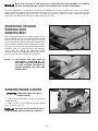
SANDING INSIDE CURVES
1.
DISCONNECT MACHINE FROM
POWER SOURCE.
2. Loosen the two lock knobs (A) Fig. 37, and remove
the top cover (B).
3. Inside curves can be sanded on the top sanding
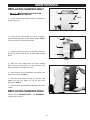
drum, as shown in Fig. 56.
REPLACE THE TOP COVER (A) FIG. 37,
WHEN SANDING INSIDE CURVES IS COMPLETE.
Fig. 56
22
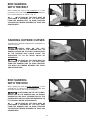
END SANDING
WITH THE BELT
When sanding the ends of wide workpieces it is more
convenient to use the sanding belt with the sanding arm
in the vertical position as shown in Fig. 57.
THE EDGE OF THE TABLE MUST BE
POSITIONED A MAXIMUM OF 1/16 INCH AWAY
FROM THE SANDING BELT TO AVOID TRAPPING
THE WORK OR FINGERS BETWEEN THE TABLE AND
SANDING BELT.
Fig. 57
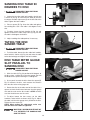
SANDING OUTSIDE CURVES
Outside curves should be sanded on the sanding disc as
shown in Fig. 58.
ALWAYS SAND ON THE LEFT
(DOWNWARD) SIDE OF THE SANDING DISC, AS
SHOWN. SANDING ON THE RIGHT (UPWARD) SIDE
OF THE SANDING DISC COULD CAUSE THE
WORKPIECE TO FLY UP WHICH COULD BE
HAZARDOUS.
THE EDGE OF THE TABLE MUST BE
POSITIONED A MAXIMUM OF 1/16 INCH AWAY
FROM THE SANDING DISC TO AVOID TRAPPING
THE WORK OR FINGERS BETWEEN THE TABLE
AND SANDING DISC.
Fig. 58
END SANDING
WITH THE DISC
When sanding the ends of narrow workpieces use the
sanding disc, as shown in Fig. 59. Move the work from
the center to the left side of the sanding disc.
ALWAYS SAND ON THE LEFT (DOWNWARD) SIDE OF THE SANDING DISC, AS SHOWN.
SANDING ON THE RIGHT (UPWARD) SIDE OF THE
SANDING DISC COULD CAUSE THE WORKPIECE TO
FLY UP WHICH COULD BE HAZARDOUS.
Fig. 59
THE EDGE OF THE TABLE MUST BE
POSITIONED A MAXIMUM OF 1/16 INCH AWAY
FROM THE SANDING DISC TO AVOID TRAPPING
THE WORK OR FINGERS BETWEEN THE TABLE AND
SANDING DISC.
23
CIRCLE SANDING WITH DISC
A circle sanding attachment is supplied with the sander.
It enables the operator to sand circles up to 24" in
diameter. Follow the guidelines below to attach and
operate the circle sanding attachment.
1.
A
DISCONNECT MACHINE FROM
POWER SOURCE.
B
C
2. Insert the stop block (A) Fig. 60 into the slot in the
sanding disc table. Line up the end of the outside edge
(B) of the block to the diameter of the circle shown on
the scale. Tighten the screw in the stop block with a
5/32 hex wrench (C) to hold the block (A) in place.
Fig. 60
D
3. Insert the guide pin (D) Fig. 61 into the center of the
oversized rough cut circle (E).
F
E
4. Insert the guide pin (D) Fig. 61 into the slot (F) of the
disc sander table. Rotate the workpiece (E) Fig. 62.
continuously while sanding. A correctly sized circle is
sanded when the guide pin (D) Fig.60 contacts the stop
block, (A) Fig. 60.
Fig. 61
E
Fig. 62
G
5. When necessary, adjust the scale (F) Fig. 63 by
loosening the two screws (G), adjusting the scale in or
out, and tightening the two screws.
F
G
Fig. 63
24
MAINTENANCE
REPLACING SANDING BELT
1.
B
A
A
DISCONNECT MACHINE FROM
POWER SOURCE.
E
2. Loosen the two lock knobs (A) Fig. 64, and remove
the top cover (B).
D
Fig. 64
3. Loosen the two lock knobs (C) Fig. 65 enough to
allow the back panel (D) Figs. 64 and 65, to open. NOTE:
The lock knobs (C) cannot be removed.
C
D
4. Release the belt tension by turning the hand lever
(E) Fig. 64. Slide the belt (F) Fig. 66 off of both sanding
drums.
C
Fig. 65
5. Slide the new sanding belt over both sanding
drums. Ensure that the belt runs in the direction of the
arrow, printed on the inside of the belt.
6. Apply tension to the sanding belt and replace the
top cover removed in STEP 2.
F
7. Close the back panel (D) Figs. 64 and 65, and
tighten the two lock knobs (C) Fig. 65 that were
loosened in STEP 3.
8. Check the belt tracking before applying power to the
sander.
REPLACING SANDING DISC
Fig. 66
See the section “ABRASIVE DISC” in the “ASSEMBLY”
section of this manual.
25
OVERLOAD PROTECTION
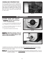
The motor supplied with your sander is equipped with a
reset overload relay button (A) Fig. 67. If the motor shuts
off or fails to start because of overloading (sanding too
heavy, using a worn sanding belt or disc, using the
sander beyond its capacity), or low voltage, turn the
power switch to the “OFF” position. Let the motor cool
three to five minutes and push the reset button (A) Fig.
67. Start the motor.
A
Fig. 67
ACCESSORIES
POWER TAKE-OFF SHAFT
1.
DISCONNECT MACHINE FROM
POWER SOURCE.
B
2. A power take-off shaft is provided on the lower end
of the sanding belt arm to accommodate accessories.
B
C
3. For access to the power take-off shaft, remove the
two screws (B) Fig. 68, and cover (C).
4. Fig. 69 shows the power take-off shaft (A).
Fig. 68
UNGUARDED ROTATING SHAFTS (A)
FIG 69 CAN CREATE AN ENTANGLEMENT HAZARD.
ALWAYS COVER THE POWER TAKE-OFF SHAFT
WHEN NOT USING ACCESSORIES.
A
Fig. 69
A complete line of accessories is available from your Delta Supplier, Porter-Cable • Delta Factory Service Centers,
and Delta Authorized Service Stations. Please visit our Web Site www.deltamachinery.com for a catalog or
for the name of your nearest supplier.
Since accessories other than those offered by Delta have not been tested with this product, use of such
accessories could be hazardous. For safest operation, only Delta recommended accessories should be
used with this product.
26
PARTS, SERVICE OR WARRANTY ASSISTANCE
All Delta Machines and accessories are manufactured to high quality standards and are serviced by a network
of Porter-Cable • Delta Factory Service Centers and Delta Authorized Service Stations. To obtain additional
information regarding your Delta quality product or to obtain parts, service, warranty assistance, or the location
of the nearest service outlet, please call 1-800-223-7278 (In Canada call 1-800-463-3582).
Two Year Limited New Product Warranty
Delta will repair or replace, at its expense and at its option, any new Delta machine, machine part, or machine accessory
which in normal use has proven to be defective in workmanship or material, provided that the customer returns the product
prepaid to a Delta factory service center or authorized service station with proof of purchase of the product within two
years and provides Delta with reasonable opportunity to verify the alleged defect by inspection. For all refurbished Delta
product, the warranty period is 180 days. Delta may require that electric motors be returned prepaid to a motor
manufacturer’s authorized station for inspection and repair or replacement. Delta will not be responsible for any asserted
defect which has resulted from normal wear, misuse, abuse or repair or alteration made or specifically authorized by
anyone other than an authorized Delta service facility or representative. Under no circumstances will Delta be liable for
incidental or consequential damages resulting from defective products. This warranty is Delta’s sole warranty and sets
forth the customer’s exclusive remedy, with respect to defective products; all other warranties, express or implied, whether
of merchantability, fitness for purpose, or otherwise, are expressly disclaimed by Delta.
27
PORTER-CABLE • DELTA SERVICE CENTERS
(CENTROS DE SERVICIO DE PORTER-CABLE • DELTA)
Parts and Repair Service for Porter-Cable • Delta Machinery are Available at These Locations
(Obtenga Refaccion de Partes o Servicio para su Herramienta en los Siguientes Centros de Porter-Cable • Delta)
ARIZONA
Tempe 85282 (Phoenix)
2400 West Southern Avenue
Suite 105
Phone: (602) 437-1200
Fax: (602) 437-2200
CALIFORNIA
Ontario 91761 (Los Angeles)
3949A East Guasti Road
Phone: (909) 390-5555
Fax: (909) 390-5554
San Leandro 94577 (Oakland)
3039 Teagarden Street
Phone: (510) 357-9762
Fax: (510) 357-7939
COLORADO
Arvada 80003 (Denver)
8175 Sheridan Blvd., Unit S
Phone: (303) 487-1809
Fax: (303) 487-1868
FLORIDA
Davie 33314 (Miami)
4343 South State Rd. 7 (441)
Unit #107
Phone: (954) 321-6635
Fax: (954) 321-6638
Tampa 33609
4538 W. Kennedy Boulevard
Phone: (813) 877-9585
Fax: (813) 289-7948
GEORGIA
Forest Park 30297 (Atlanta)
5442 Frontage Road,
Suite 112
Phone: (404) 608-0006
Fax: (404) 608-1123
ILLINOIS
Addison 60101 (Chicago)
400 South Rohlwing Rd.
Phone: (630) 424-8805
Fax: (630) 424-8895
Woodridge 60517 (Chicago)
2033 West 75th Street
Phone: (630) 910-9200
Fax: (630) 910-0360
MARYLAND
Elkridge 21075 (Baltimore)
7397-102 Washington Blvd.
Phone: (410) 799-9394
Fax: (410) 799-9398
MASSACHUSETTS
Braintree 02185 (Boston)
719 Granite Street
Phone: (781) 848-9810
Fax: (781) 848-6759
Franklin 02038 (Boston)
Franklin Industrial Park
101E Constitution Blvd.
Phone: (508) 520-8802
Fax: (508) 528-8089
MICHIGAN
Madison Heights 48071 (Detroit)
30475 Stephenson Highway
Phone: (248) 597-5000
Fax: (248) 597-5004
MINNESOTA
Minneapolis 55429
5522 Lakeland Avenue North
Phone: (763) 561-9080
Fax: (763) 561-0653
Cleveland 44125
8001 Sweet Valley Drive
Unit #19
Phone: (216) 447-9030
Fax: (216) 447-3097
MISSOURI
North Kansas City 64116
1141 Swift Avenue
Phone: (816) 221-2070
Fax: (816) 221-2897
OREGON
Portland 97230
4916 NE 122 nd Ave.
Phone: (503) 252-0107
Fax: (503) 252-2123
St. Louis 63119
7574 Watson Road
Phone: (314) 968-8950
Fax: (314) 968-2790
NEW YORK
Flushing 11365-1595 (N.Y.C.)
175-25 Horace Harding Expwy.
Phone: (718) 225-2040
Fax: (718) 423-9619
NORTH CAROLINA
Charlotte 28270
9129 Monroe Road, Suite 115
Phone: (704) 841-1176
Fax: (704) 708-4625
OHIO
Columbus 43214
4560 Indianola Avenue
Phone: (614) 263-0929
Fax: (614) 263-1238
PENNSYLVANIA
Willow Grove 19090
520 North York Road
Phone: (215) 658-1430
Fax: (215) 658-1433
TEXAS
Carrollton 75006 (Dallas)
1300 Interstate 35 N, Suite 112
Phone: (972) 446-2996
Fax: (972) 446-8157
Houston 77038
4321 Sam Houston Parkway,
West
Suite 180
Phone: (281) 260-8887
Fax: (281) 260-9989
WASHINGTON
Auburn 98001(Seattle)
3320 West Valley HWY, North
Building D, Suite 111
Phone: (253) 333-8353
Fax: (253) 333-9613
Authorized Service Stations are located in many large cities. Telephone 800-438-2486 or 731-541-6042 for assistance locating one.
Parts and accessories for Porter-Cable·Delta products should be obtained by contacting any Porter-Cable·Delta Distributor, Authorized
Service Center, or Porter-Cable·Delta Factory Service Center. If you do not have access to any of these, call 800-223-7278 and you will
be directed to the nearest Porter-Cable·Delta Factory Service Center. Las Estaciones de Servicio Autorizadas están ubicadas en muchas
grandes ciudades. Llame al 800-438-2486 ó al 731-541-6042 para obtener asistencia a fin de localizar una. Las piezas y los accesorios
para los productos Porter-Cable·Delta deben obtenerse poniéndose en contacto con cualquier distribuidor Porter-Cable·Delta, Centro
de Servicio Autorizado o Centro de Servicio de Fábrica Porter-Cable·Delta. Si no tiene acceso a ninguna de estas opciones, llame al
800-223-7278 y le dirigirán al Centro de Servicio de Fábrica Porter-Cable·Delta más cercano.
CANADIAN PORTER-CABLE • DELTA SERVICE CENTERS
ALBERTA
Bay 6, 2520-23rd St. N.E.
Calgary, Alberta
T2E 8L2
Phone: (403) 735-6166
Fax: (403) 735-6144
BRITISH COLUMBIA
8520 Baxter Place
Burnaby, B.C.
V5A 4T8
Phone: (604) 420-0102
Fax: (604) 420-3522
MANITOBA
1699 Dublin Avenue
Winnipeg, Manitoba
R3H 0H2
Phone: (204) 633-9259
Fax: (204) 632-1976
ONTARIO
505 Southgate Drive
Guelph, Ontario
N1H 6M7
Phone: (519) 767-4132
Fax: (519) 767-4131
QUÉBEC
1515 ave.
St-Jean Baptiste, Suite 160
Québec, Québec
G2E 5E2
Phone: (418) 877-7112
Fax: (418) 877-7123
1447, Begin
St-Laurent, (Montréal),
Québec
H4R 1V8
Phone: (514) 336-8772
Fax: (514) 336-3505
The following are trademarks of PORTER-CABLE·DELTA (Las siguientes son marcas registradas de PORTER-CABLE S.A.): Auto-Set®,
BAMMER®, B.O.S.S.®, Builder’s Saw®, Contractor’s Saw®, Contractor’s Saw II™, Delta®, DELTACRAFT®, DELTAGRAM™, Delta Series
2000™, DURATRONIC™, Emc²™, FLEX ®, Flying Chips™, FRAME SAW ®, Homecraft ®, INNOVATION THAT WORKS ®, Jet-Lock ®,
JETSTREAM®, ‘kickstand®, LASERLOC®, MICRO-SET®, Micro-Set®, MIDI LATHE®, MORTEN™, NETWORK™, OMNIJIG®, POCKET
CUTTER®, PORTA-BAND®, PORTA-PLANE®, PORTER-CABLE®&(design), PORTER-CABLE®PROFESSIONAL POWER TOOLS, Posi-Matic®,
Q-3®&(design), QUICKSAND®&(design), QUICKSET™, QUICKSET II®, QUICKSET PLUS™, RIPTIDE™&(design), SAFE GUARD II®, SAFELOC®, Sanding Center®, SANDTRAP®&(design), SAW BOSS®, Sawbuck™, Sidekick®, SPEED-BLOC®, SPEEDMATIC®, SPEEDTRONIC®,
STAIR EASE®, The American Woodshop®&(design), The Lumber Company®&(design), THE PROFESSIONAL EDGE®, THE PROFESSIONAL
SELECT ®, THIN-LINE™, TIGER ®, TIGER CUB ®, TIGER SAW ®, TORQBUSTER ®, TORQ-BUSTER ®, TRU-MATCH™, TWIN-LITE ®,
UNIGUARD®, Unifence®, UNIFEEDER™, Unihead®, Uniplane™, Unirip®, Unisaw®, Univise®, Versa-Feeder®, VERSA-PLANE® , WHISPER
SERIES®, WOODWORKER’S CHOICE™.
Trademarks noted with ™ and ® are registered in the United States Patent and Trademark Office and may also be registered in other
countries. Las Marcas Registradas con el signo de ™ y ® son registradas por la Oficina de Registros y Patentes de los Estados Unidos y
también pueden estar registradas en otros países.
Printed in U.S.A.
PC-0603-149