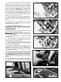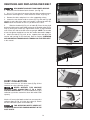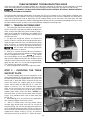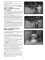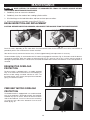
1
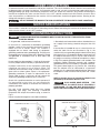
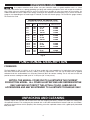
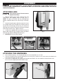
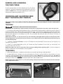
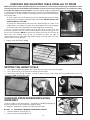
(Models 31-250, 31-255X)
PART NO. 406-13-651-0021 - 06-19-03
Copyright © 2003 Delta Machinery
To learn more about DELTA MACHINERY
visit our website at: www.deltamachinery.com.
For Parts, Service, Warranty or other Assistance,
please call
1-800-223-7278 (In Canada call 1-800-463-3582).
INSTRUCTION MANUAL
18" x 36" Drum Sander
SAFETY GUIDELINES - DEFINITIONS
This manual contains information that is important for you to know and understand. This information relates to protecting YOUR SAFETY and PREVENTING EQUIPMENT PROBLEMS. To help you recognize this information, we use the
symbols to the right. Please read the manual and pay attention to these sections.
Indicates an imminently hazardous situation which, if not avoided, will result in death or serious injury.
Indicates a potentially hazardous situation which, if not avoided, could result in death or serious injury.
Indicates a potentially hazardous situation which, if not avoided, may result in minor or moderate injury.
Used without the safety alert symbol indicates potentially hazardous situation which, if not avoided, may
result in property damage.
SOME DUST CREATED BY POWER SANDING, SAWING, GRINDING, DRILLING, AND OTHER
CONSTRUCTION ACTIVITIES contains chemicals known to cause cancer, birth defects or other reproductive harm.
Some examples of these chemicals are:
· lead from lead-based paints,
· crystalline silica from bricks and cement and other masonry products, and
· arsenic and chromium from chemically-treated lumber.
Your risk from these exposures varies, depending on how often you do this type of work. To reduce your exposure to
these chemicals: work in a well ventilated area, and work with approved safety equipment, always wear MSHA/NIOSH
approved, properly fitting face mask or respirator when using such tools.
GENERAL SAFETY RULES
READ AND UNDERSTAND ALL WARNINGS AND OPERATING INSTRUCTIONS BEFORE
USING THIS EQUIPMENT. Failure to follow all instructions listed below, may result in electric shock,
fire, and/or serious personal injury or property damage.
IMPORTANT SAFETY INSTRUCTIONS
Woodworking can be dangerous if safe and proper operating procedures are not followed. As with all machinery, there
are certain hazards involved with the operation of the product. Using the machine with respect and caution will
considerably lessen the possibility of personal injury. However, if normal safety precautions are overlooked or ignored,
personal injury to the operator may result. Safety equipment such as guards, push sticks, hold-downs, featherboards,
goggles, dust masks and hearing protection can reduce your potential for injury. But even the best guard won’t make
up for poor judgment, carelessness or inattention. Always use common sense and exercise caution in the workshop.
If a procedure feels dangerous, don’t try it. Figure out an alternative procedure that feels safer. REMEMBER: Your
personal safety is your responsibility. For additional information please visit our website www.deltamachinery.com.
This machine was designed for certain applications only. Delta Machinery strongly recommends that this
machine not be modified and/or used for any application other than that for which it was designed. If you have any
questions relative to a particular application, DO NOT use the machine until you have first contacted Delta to determine
if it can or should be performed on the product.
Technical Service Manager
Delta Machinery
4825 Highway 45 North
Jackson, TN 38305
(IN CANADA: 505 SOUTHGATE DRIVE, GUELPH, ONTARIO N1H 6M7)
2
FAILURE TO FOLLOW THESE RULES MAY RESULT IN SERIOUS PERSONAL INJURY.
1.
2.
3.
4.
5.
6.
7.
8.
9.
10.
11.
12.
FOR YOUR OWN SAFETY, READ THE INSTRUCTION MANUAL BEFORE OPERATING THE
MACHINE. Learning the machine’s application,
limitations, and specific hazards will greatly
minimize the possibility of accidents and injury.
USE CERTIFIED SAFETY EQUIPMENT. Eye
protection equipment should comply with ANSI
Z87.1 standards, hearing equipment should
comply with ANSI S3.19 standards, and dust mask
protection should comply with MSHA/NIOSH
certified respirator standards. Splinters, air-borne
debris, and dust can cause irritation, injury, and/or
illness.
DRESS PROPERLY. Do not wear tie, gloves, or
loose clothing. Remove watch, rings, and other
jewelry. Roll up your sleeves. Clothing or jewelry
caught in moving parts can cause injury.
DO NOT USE THE MACHINE IN A DANGEROUS
ENVIRONMENT. The use of power tools in damp
or wet locations or in rain can cause shock or
electrocution. Keep your work area well-lit to
prevent tripping or placing arms, hands, and
fingers in danger.
MAINTAIN ALL TOOLS AND MACHINES IN PEAK
CONDITION. Keep tools sharp and clean for best and
safest performance. Follow instructions for lubricating
and changing accessories. Poorly maintained tools and
machines can further damage the tool or machine and/or
cause injury.
CHECK FOR DAMAGED PARTS. Before using the
machine, check for any damaged parts. Check for
alignment of moving parts, binding of moving
parts, breakage of parts, and any other conditions
that may affect its operation. A guard or any other
part that is damaged should be properly repaired
or replaced. Damaged parts can cause further
damage to the machine and/or injury.
KEEP THE WORK AREA CLEAN. Cluttered areas and
benches invite accidents.
KEEP CHILDREN AND VISITORS AWAY. Your shop is
a potentially dangerous environment. Children and visitors
can be injured.
REDUCE THE RISK OF UNINTENTIONAL STARTING.
Make sure that the switch is in the “OFF” position
before plugging in the power cord. In the event of
a power failure, move the switch to the “OFF”
position. An accidental start-up can cause injury.
USE THE GUARDS. Check to see that all guards
are in place, secured, and working correctly to
prevent injury.
REMOVE ADJUSTING KEYS AND WRENCHES
BEFORE STARTING THE MACHINE. Tools, scrap
pieces, and other debris can be thrown at high
speed, causing injury.
USE THE RIGHT MACHINE. Don’t force a
machine or an attachment to do a job for which it
was not designed. Damage to the machine and/or
injury may result.
13.
14.
15.
16.
17.
18.
19.
20.
21.
22.
23.
24.
3
USE RECOMMENDED ACCESSORIES. The use
of accessories and attachments not recommended by Delta may cause damage to the
machine or injury to the user.
USE THE PROPER EXTENSION CORD. Make
sure your extension cord is in good condition.
When using an extension cord, be sure to use one
heavy enough to carry the current your product will
draw. An undersized cord will cause a drop in line
voltage, resulting in loss of power and overheating.
See the Extension Cord Chart for the correct size
depending on the cord length and nameplate
ampere rating. If in doubt, use the next heavier
gauge. The smaller the gauge number, the heavier
the cord.
SECURE THE WORKPIECE. Use clamps or a vise to
hold the workpiece when practical. Loss of control
of a workpiece can cause injury.
FEED THE WORKPIECE AGAINST THE DIRECTION
OF THE ROTATION OF THE BLADE, CUTTER, OR
ABRASIVE SURFACE. Feeding it from the other
direction will cause the workpiece to be thrown out
at high speed.
DON’T FORCE THE WORKPIECE ON THE
MACHINE. Damage to the machine and/or injury
may result.
DON’T OVERREACH. Loss of balance can make
you fall into a working machine, causing injury.
NEVER STAND ON THE MACHINE. Injury could occur if
the tool tips, or if you accidentally contact the cutting tool.
NEVER LEAVE THE MACHINE RUNNING UNATTENDED. TURN THE POWER OFF. Don’t leave the machine
until it comes to a complete stop. A child or visitor could
be injured.
TURN THE MACHINE “OFF”, AND DISCONNECT THE
MACHINE FROM THE POWER SOURCE before
installing or removing accessories, before adjusting
or changing set-ups, or when making repairs. An
accidental start-up can cause injury.
MAKE YOUR WORKSHOP CHILDPROOF WITH
PADLOCKS, MASTER SWITCHES, OR BY
REMOVING STARTER KEYS. The accidental
start-up of a machine by a child or visitor could
cause injury.
STAY ALERT, WATCH WHAT YOU ARE DOING,
AND USE COMMON SENSE. DO NOT USE THE
MACHINE WHEN YOU ARE TIRED OR UNDER
THE INFLUENCE OF DRUGS, ALCOHOL, OR
MEDICATION. A moment of inattention while
operating power tools may result in injury.
THE DUST GENERATED by certain woods and
wood products can be injurious to your health.
Always operate machinery in well-ventilated areas,
and provide for proper dust removal. Use wood
dust collection systems whenever possible.
ADDITIONAL SAFETY RULES
FOR DRUM SANDERS
FAILURE TO FOLLOW THESE RULES MAY RESULT IN SERIOUS PERSONAL INJURY.
1.
DO NOT OPERATE THIS TOOL UNTIL it is
assembled and installed according to the
instructions.
2.
OBTAIN ADVICE from your supervisor, instructor,
or another qualified person if you are not familiar
with the operation of this tool.
3.
FOLLOW ALL WIRING CODES and recommended
electrical connections.
4.
COVER POWER TAKE-OFF SHAFT when not
using accessories. Unguarded rotating shafts can
create an entanglement hazard which can result in
injury.
5.
USE A DUST COLLECTION SYSTEM with this
tool.
6.
CAUTION: THIS MACHINE IS DESIGNED TO
SAND WOOD or wood-like products only.
Sanding or grinding metal could result in fire, injury,
and/or damage to the product.
7.
CHECK THE TABLE BELT TRACKING to prevent
belt run-off.
8.
CHECK BELTS FOR WEAR and for tension.
9.
CLEAR THE SANDING AREA and infeed/
outfeed tables of all objects (tools, scrap pieces,
etc.) prior to starting tool.
10.
DO NOT sand pieces of material that are shorter
than 7" in length or thinner than 1/32".
11.
SUPPORT ALL SANDING WORKPIECES with a
table or additional support at table height. Curved
work on an outer sanding drum is the only
exception.
12.
DRESS PROPERLY. DO NOT WEAR LOOSE
CLOTHING OR JEWELRY. CONTAIN LONG HAIR.
KEEP YOUR HAIR, CLOTHING, AND GLOVES
AWAY FROM MOVING PARTS. Loose clothes,
jewelry, or long hair can be caught in moving parts.
13.
PREVENT THE WORKPIECE FROM CONTACTING
THE SANDING BELT before starting the tool.
14.
AVOID AWKWARD HAND POSITIONS. A sudden
slip could cause a hand to contact the sanding belt.
15.
NEVER WEAR GLOVES or hold the work with a
rag when sanding.
16.
HOLD THE WORK FIRMLY when sanding.
17.
SAND with the grain of the wood
18.
FEED WORK against the drum rotation.
19.
NEVER perform layout, assembly, or set-up work
on the tables when the tool is operating.
20. DISCONNECT THE TOOL from the power source
before installing or removing accessories, before
adjusting or changing set-ups, or when making
repairs.
21. DISCONNECT THE TOOL from the power source,
and clean the table/work area before leaving the
tool. LOCK THE SWITCH IN THE “OFF”
POSITION to prevent unauthorized use.
22. ADDITIONAL INFORMATION regarding the safe
and proper operation of power tools (i.e. a safety
video) is available from the Power Tool Institute,
1300 Sumner Avenue, Cleveland, OH 44115-2851
(www.powertoolinstitute.com). Information is also
available from the National Safety Council, 1121
Spring Lake Drive, Itasca, IL 60143-3201. Please
refer to the American National Standards Institute
ANSI 01.1 Safety Requirements for Woodworking
Machines and the U.S. Department of Labor OSHA
1910.213 Regulations.
SAVE THESE INSTRUCTIONS.
Refer to them often and use them to instruct others.
4
POWER CONNECTIONS
A separate electrical circuit should be used for your machines. This circuit should not be less than #12 wire and should
be protected with a 20 Amp time lag fuse. If an extension cord is used, use only 3-wire extension cords which have 3prong grounding type plugs and matching receptacle which will accept the machine’s plug. Before connecting the
machine to the power line, make sure the switch is in the “OFF” position and be sure that the electric current is of the
same characteristics as indicated on the machine. All line connections should make good contact. Running on low
voltage will damage the machine.
DO NOT EXPOSE THE MACHINE TO RAIN OR OPERATE THE MACHINE IN DAMP LOCATIONS.
MOTOR SPECIFICATIONS
Your machine is wired for 120 volt, 60 HZ alternating current. Before connecting the machine to the power source,
make sure the switch is in the “OFF” position.
GROUNDING INSTRUCTIONS
THIS MACHINE MUST BE GROUNDED WHILE IN USE TO PROTECT THE OPERATOR FROM
ELECTRIC SHOCK.
1. All grounded, cord-connected machines:
2. Grounded, cord-connected machines intended for use
on a supply circuit having a nominal rating less than 150
volts:
In the event of a malfunction or breakdown, grounding
provides a path of least resistance for electric current to
reduce the risk of electric shock. This machine is
equipped with an electric cord having an equipmentgrounding conductor and a grounding plug. The plug must
be plugged into a matching outlet that is properly installed
and grounded in accordance with all local codes and
ordinances.
If the machine is intended for use on a circuit that has an
outlet that looks like the one illustrated in Fig. A, the
machine will have a grounding plug that looks like the plug
illustrated in Fig. A. A temporary adapter, which looks like
the adapter illustrated in Fig. B, may be used to connect
this plug to a matching 2-conductor receptacle as shown
in Fig. B if a properly grounded outlet is not available. The
temporary adapter should be used only until a properly
grounded outlet can be installed by a qualified electrician.
The green-colored rigid ear, lug, and the like, extending
from the adapter must be connected to a permanent
ground such as a properly grounded outlet box. Whenever
the adapter is used, it must be held in place with a metal
screw.
Do not modify the plug provided - if it will not fit the outlet,
have the proper outlet installed by a qualified electrician.
Improper connection of the equipment-grounding
conductor can result in risk of electric shock. The
conductor with insulation having an outer surface that is
green with or without yellow stripes is the equipmentgrounding conductor. If repair or replacement of the
electric cord or plug is necessary, do not connect the
equipment-grounding conductor to a live terminal.
NOTE: In Canada, the use of a temporary adapter is not
permitted by the Canadian Electric Code.
Check with a qualified electrician or service personnel if
t h e g ro u n d i n g i n s t r u c t i o n s a re n o t c o m p l e t e l y
understood, or if in doubt as to whether the machine is
properly grounded.
IN ALL CASES, MAKE CERTAIN
THE
R E C E P TA C L E I N Q U E S T I O N I S P R O P E R LY
G R O U N D E D . I F Y O U A R E N O T S U R E H AV E A
QUALIFIED ELECTRICIAN CHECK THE RECEPTACLE.
Use only 3-wire extension cords that have 3-prong
grounding type plugs and matching 3-conductor
receptacles that accept the machine’s plug, as shown in
Fig. A.
Repair or replace damaged or worn cord immediately.
GROUNDED OUTLET BOX
GROUNDED OUTLET BOX
GROUNDING
MEANS
CURRENT
CARRYING
PRONGS
ADAPTER
GROUNDING BLADE
IS LONGEST OF THE 3 BLADES
Fig. A
5
Fig. B
EXTENSION CORDS
Use proper extension cords. Make sure your extension cord is in good condition and is a 3-wire
extension cord which has a 3-prong grounding type plug and matching receptacle which will accept the machine’s
plug. When using an extension cord, be sure to use one heavy enough to carry the current of the machine. An
undersized cord will cause a drop in line voltage, resulting in loss of power and overheating. Fig. D, shows the correct
gauge to use depending on the cord length. If in doubt, use the next heavier gauge. The smaller the gauge number,
the heavier the cord.
MINIMUM GAUGE EXTENSION CORD
RECOMMENDED SIZES FOR USE WITH STATIONARY ELECTRIC MACHINES
Ampere
Rating
Volts
Total Length
of Cord in Feet
Gauge of
Extension Cord
0-6
0-6
0-6
0-6
120
120
120
120
up to 25
25-50
50-100
100-150
18 AWG
16 AWG
16 AWG
14 AWG
6-10
6-10
6-10
6-10
120
120
120
120
up to 25
25-50
50-100
100-150
18 AWG
16 AWG
14 AWG
12 AWG
10-12
10-12
10-12
10-12
120
120
120
120
up to 25
25-50
50-100
100-150
16 AWG
16 AWG
14 AWG
12 AWG
12-16
12-16
12-16
120
120
120
up to 25
25-50
14 AWG
12 AWG
GREATER THAN 50 FEET NOT RECOMMENDED
Fig. D
FUNCTIONAL DESCRIPTION
FOREWORD
The Delta Model 31-250 / 31-255X is an 18" x 36" drum sander with a two-speed drum. Its single-piece frame and castiron table construction provides accuracy, stability, and easy adjustments. This unit can be fitted with an optional
outboard shaft that accommodates an accessory pneumatic drum for contour sanding. The 31-250 and 31-255X will
provide accurate sanding for wood up to 18" in one pass (36" in two passes).
NOTICE: THE MANUAL COVER PHOTO ILLUSTRATES THE CURRENT
PRODUCTION MODEL. ALL OTHER ILLUSTRATIONS ARE REPRESENTATIVE
ONLY AND MAY NOT DEPICT THE ACTUAL COLOR, LABELING OR
ACCESSORIES AND MAY BE INTENDED TO ILLUSTRATE TECHNIQUE ONLY.
UNPACKING AND CLEANING
Carefully unpack the machine and all loose items from the shipping container(s). Remove the protective coating from
all unpainted surfaces. This coating may be removed with a soft cloth moistened with kerosene (do not use acetone,
gasoline or lacquer thinner for this purpose). After cleaning, cover the unpainted surfaces with a good quality household
floor paste wax.
6
DRUM SANDER PARTS
CAUTION TAG
CAUTION: Pay close attention to caution tags
attached to this machine and follow these instructions
precisely. This machine is heavy. Remove the
container from around the machine. DO NOT lift it from
the container. Carefully unpack all loose items from the
shipping container and cut the carton from around the
machine.
CARTON CONTENTS
1
2
7
4 5
6
8
10
3
CAUTION:
TAGS
1.
2.
3
4.
5.
6.
11
Drum Sander
Legs (2)
Feed Table
Cable tie (in instruction packet)
Thickness Scale (in instruction packet)
1/8" T-Handle Hex Wrench(in instruction packet)
9
7.
8.
9.
10.
11.
7
Table Raising Handwheel
5/16-18 x 1” Socket Head Screws (4)
5/16" Lock-washers (4)
5/16-18 x 5/8” Carriage Head Screws (12)
5/16-18 Flange Nuts (16)
ASSEMBLY
FOR YOUR OWN SAFETY, DO NOT CONNECT THE MACHINE TO THE POWER SOURCE UNTIL
THE MACHINE IS COMPLETELY ASSEMBLED AND YOU READ AND UNDERSTAND THE ENTIRE
INSTRUCTION MANUAL.
ATTACHING LEGS
This machine is heavy. Use two or more
people when lifting.
1. With the machine on its back, resting on the two
wood blocks (not supplied), attach the legs. (Fig. 1).
NOTE: The legs are universal but the mounting hole
pattern is different front to rear. See (A) Fig. 2A and Fig.
2B.
2. Attach the leg that goes under the motor first. Insert
six carriage head screws through the machine and the
leg and secure with flange nuts (A) Fig. 2A. Attach the
other leg to the machine using the remaining six carriage
head screws and hex nuts. Tighten securely.
4. A cable tie is supplied with the machine to keep the
power cord inside the leg assembly. Secure the power
cord with the cable tie through hole (A) Fig. 2C.
5.
Fig. 1
CAREFULLY lift the machine upright.
A
A
A
Fig. 2A
Fig. 2B
Fig. 2C
ATTACHING THE HANDWHEEL
1.
2.
3.
Place handwheel (A) Fig. 3, on shaft (B) and align set screw with drilled recess in shaft.
Fasten the handwheel to the shaft by tightening the set screw (C) Fig. 4. Make sure set screw contacts the drilled recess
in the shaft and not the O.D. of the shaft.
The machine is shipped with the support plate lowered to the bottom. Turn the handwheel counterclockwise two
turns to raise the support plate off the bottom stops.
A
C
B
Fig. 4
Fig. 3
8
ATTACHING AND LEVELING FEED TABLE
1.
Remove the front and rear shipping bolts that were installed to stabilize the support plate during transit.
These bolts, one shown at (N) Fig. 5, should be removed before attaching table. Use a ½" wrench to hold hex stop
post (S) then with another ½" wrench loosen and remove hex bolts (N)
NOTE: DO NOT remove the hex stop post (S) Fig. 5.
2. The abrasive belt and the motor for the feed table are shipped assembled. Place the feed table (A) Fig. 5 on the support
plate (P), inserting the motor side first. Align holes in table (two of which are shown at C) with top of leveling screws (B).
Make sure the table is not sitting on any of the lockwashers attached to leveling screws (B).
3. Fasten the table assembly (A) to the support plate (P) with four 5/16" socket head screws with lock washers through the
holes (D), and secure with flange nuts, two of which are shown in (F) Fig. 6D. Tighten securely.
4. With a ½" wrench hold the hex top of the front, right leveling screw (L) Fig .6A. Then using a 3/16" hex wrench loosen
screw (B) four full turns. Turn leveling screw clockwise Fig. 6B until it no longer touches the support plate (P) as shown. Then
turn it counterclockwise until it just touches the support plate (P) Fig. 6C without raising the plate as shown at (O). Hold the
hex top of the leveling screw (L) Fig. 6A and tighten hex screw (B).
D
C
B
B
C
A
B
N
B
CAUTION:
TAG
B
O
P
P
S
L
L
P
Fig. 6B
Fig. 6A
Fig. 5
P
L
Fig. 6C
A
F
P
Fig. 6D
ATTACHING THICKNESS SCALE
1. Remove screw and washer (A) Fig. 7.
2. Place thickness scale (B) Fig. 8 over the hole and replace screw and washer (A).
3. Loosen screw (C) Fig. 9, and position pointer against scale (B) Fig. 9. Tighten screw (C) Fig. 9.
IMPORTANT: Refer to section “CHECKING AND ADJUSTING TABLE HEIGHT” in this manual for adjusting scale.
A
A
B
B
B
Fig. 7
C
Fig. 8
Fig. 9
CONNECTING FEED MOTOR TO
FEED/SPEED SWITCH ASSEMBLY
A
The table feed motor (A) Fig. 10 is
located on the side of the feed table (B). Before
connecting the feed motor to the feed-speed switch
disconnect machine from power source.
C
D
1. Insert the feed/speed switch assembly connector
(C) Fig. 10 into the motor connector (D) . Connector is
polarized and will fit only one way.
B
To avoid damage DO NOT connect the
motor to any other power source.
Fig. 10
9
OPERATING CONTROLS AND ADJUSTMENTS
STARTING AND STOPPING THE
MACHINE
1. The drum motor on/off switch (A) Fig. 12 is located
underneath the switch shield (B). To turn the drum
“ON”, move switch (A) to the “ON” (up) position.
B
2. To turn the drum “OFF”, push down on switch shield
(B) Fig. 13. NOTE: This switch only controls the drum.
See “TABLE FEED/SPEED SWITCH” for feed table
switch instructions.
A
Fig. 12
B
Fig. 13
LOCKING THE DRUM SWITCH
IN THE “OFF” POSITION
D
IMPORTANT: When the machine is not in use, the
switch should be locked in the “OFF” position to prevent
unauthorized use, using a padlock (C) Fig. 14 with a
3/16" diameter shackle.
C
Fig. 14
TABLE FEED/SPEED SWITCH
The “FEED/SPEED” switch, (A) Fig. 15 is located above
the drum motor on/off switch shield (B). Rotate the knob
(A) Fig. 15 clockwise to turn the table motor on and
continue to turn it in order to increase the table
feed/speed rates and counter-clockwise to decrease the
speed rates.
A
To turn the feed table "OFF", turn the knob in a counterclockwise direction until it CLICKS "OFF".
B
Fig. 15
10
RAISING AND LOWERING
THE FEED TABLE
A
To raise the feed table, turn the handwheel (A) Fig. 16 counterclockwise. To lower the feed table, turn hand-wheel, (A) Fig. 16
clockwise. NOTE: Each 1/4 turn of handwheel (A) will increase or
decrease the height of the table by 1/64".
CHECKING AND ADJUSTING FEED
BELT TRACKING AND TENSION
Fig. 16
IMPORTANT: READ THIS COMPLETE SECTION BEFORE MAKING ANY ADJUSTMENTS TO BELT TRACKING OR
TENSION.
TRACKING
DISCONNECT MACHINE FROM POWER SOURCE.
IMPORTANT: The feed belt runs slowly, therefore response time to adjustments may also be slow. Take your time.
1. The tracking and tensioning of the feed belt has been set at the factory. Before making any adjustments place a reference
mark on the table on either side of the belt using a lead pencil. Using a visual aid mark will help the user observe the direction
of belt movement over time. Turn feed/speed knob (E) Fig. 17A “ON" and adjust to the maximum speed. Let the belt run and
observe tracking direction. If the belt does not make any measurable side movement within five minutes of running, no
adjustment is needed.
NOTE: With a new belt, it is not unusual for one side of the belt to be tighter than the other to make the belt track.
Frequent adjustments are normal for the first few hours use to allow for belt stretch. Adjustments to belt tracking can
also affect belt tension.
2. If belt (F) is tracking to the right, use the 1/8" T-handle hex wrench provided. Turn the right set screw (B) Fig. 17A
clockwise 1/4 turn or less.
3. If belt (F) is tracking to the left, use the 1/8" T-handle hex wrench provided. Turn the right set screw (B) Fig. 17A
counterclockwise 1/4 turn or less.
NOTE: Only adjust one side at a time and let the movement stabilize before adjusting again. Continue to tighten or
loosen this adjustment until the feed belt is tracking properly.
TENSIONING
4.
Belt tension adjustment is needed if the belt slips on the rear drive roller during sanding operations.
5. To adjust belt tension, turn both set screws (A) and (B) Fig. 17A (one is shown at (B) Fig. 17B) clockwise in 1/4 turn
increments, until the feed belt is tensioned sufficiently to prevent slipping. NOTE: When adjusting belt tension, turn both set
screws the same amount. DO NOT over tension the belt. Excessive tension will cause premature wear of belt, bearings and
overload the motor. Listen for motor load speed changes when adjusting belt tension.
NOTE: Adjustments to belt tension can affect belt tracking. Frequent adjustments are normal for the first few hours
use to allow for belt stretch.
E
B
A
B
F
Fig. 17A
Fig. 17B
11
CHECKING AND ADJUSTING TABLE PARALLEL TO DRUM
NOTE: The table to drum parallelism (D) Fig. 18 has been set at the factory. Distance (D) should be the same
front to back over the entire width of the feed belt. It is best to measure the board thickness at several places along
the length and width to ensure parallelism. To check and/or to adjust parallelism (D) follow the steps below.
1. To check if the feed table is parallel with the drum cylinder, sand a wide board (B) Fig.
19A (preferably 12" or more in width x 2 feet long) until it is flat across the total surface
area on both sides.
A. To do a quick check, draw pencil lines (C) Fig. 19B extending across the width
of the board at several places along the length of the board. DO NOT ADJUST THE
TABLE HEIGHT AT THIS TIME.
B. Reverse the board (end for end) and run the board through the sander. If the
sanding table is set properly, the drawn lines will disappear. If the lines still appear
on the left or right side of the board, the table height must be adjusted.
D
2. Use a ½” wrench to hold the leveling screws (E) and (F) Fig. 20. Insert 3/16" hex
wrench (D), and loosen the hex screws. Rotate leveling screws (E) and (F) Fig. 20, one
flat at a time until parallel. NOTE: One flat on the leveling screw will raise or lower the
table .010". Turn leveling screw (E) Fig. 20 clockwise to lower the table or
counterclockwise to raise the table. Adjust both leveling screws (E) and (F) the same
amount and in the same direction.
D
Fig. 18
3. Tighten screws loosened in step 2.
D
B
C
E
F
Fig. 19A
Fig. 19B
Fig. 20
SETTING THE HEIGHT SCALE
1.
Run a piece of lumber through the drum sander (Fig. 22) to finish one side of the board.
2.
Use a square (A) Fig. 23 to measure the thickness of the lumber.
3. Loosen the screw (B) Fig. 24. Move scale up or down until the cursor shows the exact board thickness that was
measured in STEP 2. Tighten the screw.
B
A
Fig. 22
Fig. 24
Fig. 23
CHANGING DRUM SPEEDS/REPLACING
DRIVE BELT
The drum sander has two drum speeds - 2210 SFM or 3300 SFM, depending on
the belt arrangement on the motor pulley and drum pulley.
To change the sanding drum speeds or to replace the drive belt:
A
G
B
DISCONNECT MACHINE FROM POWER SOURCE.
1.
Raise the top drum cover (A) Fig. 25.
2.
Remove the two hole plugs (B) Fig. 25.
G
12
Fig. 25
3. Use a 9/16” socket with an extension (not supplied).
Place it in one of the two holes where the hole plugs were
removed. Loosen one hex bolt, then the other to relieve
tension on the motor. (One is shown at (D) Fig. 26). Apply
upward pressure on the motor (located under the machine)
to relieve tension on the belt. Replace or change the belt
positions on the pulleys. IMPORTANT: When the belt is on
the inner pulleys (F) Fig. 26, the sanding drum speed is 3300
SFM. When the belt is positioned on the outer pulleys (G)
Fig. 27, drum speed is 2210 SFM. NOTE: Position the polyv drive belt on the pulleys correctly to provide maximum
performance with minimal belt wear.
F
D
F
E
4. After the belt (E) Fig. 28 has been repositioned or
replaced on the pulleys, apply downward pressure on the
motor and tighten the two hex head bolts (D) (loosened in
STEP 3).
Fig. 26
5. Use light finger pressure on the belt (E) Fig. 28 midway
between pulleys to check for proper tension. A deflection of
approximately 3/16" is correct.
6.
E
Replace the hole plugs (B) Fig. 25.
REMOVING AND REPLACING DRUM
SANDING BELT
G
The drum sanding belt is held on the drum with a spring
clip located on each side of the drum.
DISCONNECT MACHINE FROM POWER
SOURCE.
1. Open drum cover (B) Fig. 31 to remove the sanding
belt (A) Fig. 29.
2. Press spring clips (C) Fig. 29 together and remove
one end of sanding belt (A). NOTE: Clip must be fully
depressed against the drum support.
3. Rotate the drum, (D) Fig. 31 by hand until you reach
the other end spring clip. Squeeze the spring clip to open
and remove the sanding belt (A).
4. To replace the sanding belt, press spring clip (C) Fig.
30 together and insert one end of sanding belt (A)
through the slot (S) in the drum and into the spring clip
(C). The taper cut end of the sanding belt must line up
with the edge of the drum.
5. Tightly wrap sanding belt (A) Fig. 31 around the drum
cylinder (D), keeping each wrap close to the previous
edge. IMPORTANT: DO NOT OVERLAP THE EDGES OF
THE SANDING BELT (A). Insert the other end of the
sanding belt into the left spring clip (C) Fig. 29 as tightly as
possible.
6. The sanding belt will stretch during use. Periodically,
press spring clip (C) Fig. 29 and reinsert stretched length
into the clip.
Fig. 27
D
E
Fig. 28
A
D
C
A
D
Fig. 29
D
A
S
C
Fig. 30
13
Fig. 31
B
REMOVING AND REPLACING FEED BELT
DISCONNECT MACHINE FROM POWER SOURCE.
1. Disconnect the DC Motor Quick Connect. (see Fig. 10).
2. Use a 1/4" hex wrench to remove the four table mounting screws,
lockwashers and flange nuts , two of which are shown at (A) Fig. 32.
3. Remove the table, and place it on a firm supporting surface.
4. Loosen the two socket head set screws (D) Fig. 33A and Fig. 33B
equally at each side of the table until tension is relieved on roller (E).
NOTE: Count the number of turns as you loosen the screws.
5.
Slide the feed belt (A) Fig. 34, off table (B). Place the new feed
belt on the table and re-apply slight tension to the feed belt roller (E) Fig.
33A, by turning two screws (D). Tighten both screws an equal amount
until at least one side of the belt starts to get tight. NOTE: The number
of turns to tighten should be less than the number loosened in step 4.
6. Attach the table (F) Fig. 33A, to the support plate and adjust the
tension and tracking on the feed belt. Refer to section “CHECKING
AND ADJUSTING TRACKING AND TENSION ON THE FEED BELT”
in this manual.
A
A
Fig. 32
D
B
F
D
E
Fig. 33A
D
Fig. 33B
A
B
DUST COLLECTION
The drum cover has a 4” O.D. dust chute (A) Fig. 35 that
connects to a dust collection system.
NEVER OPERATE THIS MACHINE
WITHOUT FIRST CONNECTING IT TO A DUST
COLLECTION SYSTEM. It is recommended that a dust
collection system be used with at least 400 to 600 CFM
capacity.
Fig. 34
B
A
Attach a 4" hose to the hood, or attach an accessory dust
collector elbow (B) Fig. 35 to the dust chute (A). Attach
the dust collection system to the elbow (B).
FOR OPERATOR SAFETY, NEVER PUT
FINGERS OR ANY OTHER FOREIGN OBJECT IN THE
DUST CHUTE.
Fig. 35
14
FREQUENTLY ASKED QUESTIONS
WHAT FACTORS AFFECT SANDING OPERATIONS?
A. SANDING BELT GRIT
1. 36 grit – Used for very aggressive stock removal, glue removal, or for sanding rough boards. Leaves a rough
finish.
2. 60 grit – Used for heavy stock removal and rough surfaces, and for truing warped material. Leaves a rough finish.
3. 80 grit – Used for general purpose sanding, stock removal, surfacing, and rough finishing. Leaves a marked
finish.
4. 120 grit – Used for minimal stock removal and for finishing. Leaves a fine marked finish.
5. 180 grit. – Used for fine finishing. Leaves a smooth finish.
6. 220 grit – For very fine finishing. Leaves a very smooth finish.
For best results, sand first with a coarse grit belt, and work toward a finer grit belt.
IMPORTANT: Sanding progression should not exceed more than two belt grits at one time. Watch for the sawdust
loading and dulling of the grit. The extra load will cause the sander to work inefficiently.
B. WIDTH OF BOARD
As board width increases the load on the belt and motor also increases. This additional loading can be reduced by:
a. reducing the conveyor belt speed.
b. reducing the depth of stock removal.
NOTE: The sander will remove stock to a maximum width of 18" in one pass.
C. TYPES OF WOOD
Hardwoods (oak, hickory, cherry), knots, rosin, or wet wood all place a heavy load on the sander. To make your
sander work more efficiently:
a. reduce the conveyor belt speed.
b. reduce the depth of stock removal.
D. CONVEYOR BELT SPEED
The conveyor belt speed is 0 - 12 feet per minute.
To control the speed of the conveyor belt, turn the knob counter-clockwise to slow it down and clockwise to speed
it up.
Stock can be removed more quickly by using a fast speed, but the machine works much harder, and the wood is
left with a rougher finish. Slowing the speed will lighten the load of the sander, and make the finish better, but it will
increase the sanding time.
WHEN DO I CHANGE THE DRUM SPEED?
The machine has two drum settings:
a. High Speed (3300 Surface Feet Per Minute). This setting should mostly be used with a finer grit belt with the
conveyor belt speed set to very slow. The material removal should be set at a very low amount, with increases not
to exceed 1/16 of a handwheel turn. Example: A 1/4 turn is 90 degrees, 1/8 turn is 45 degrees, 1/16 turn is 22.5
degrees.
b. Low Speed (2210 Surface Feet Per minute). Used for general purpose sanding, stock removal, surfacing, and
rough finishing.
The machine is shipped from the factory set on the low speed. To change to the higher speed, refer to “CHANGING
DRUM SPEEDS/REPLACING DRIVE BELT” in this manual for instructions.
WHAT IS RECOMMENDED FOR DUST COLLECTION
1. It is recommended that a dust collection system be used with at least 400 to 600 CFM capacity.
HOW DO I SAND FACE FRAMES and RAISED PANEL DOORS.
1. Some doors have boards with the grain running at 90 degrees. We suggest using finer grit paper, removing
minimal amount of stock, and slowing down the feed rate.
15
WHAT CAUSES BURN MARKS
Burning the wood can be caused by several things. We suggest checking for; sanding belt overlap on the drum
wrap, sanding paper loading up, too much stock removal with too fine a grit paper, too slow a feed rate, and dull
or worn sand paper.
WHEN DO I MAKE TABLE HEIGHT ADJUSTMENTS FOR MATERIAL
REMOVAL?
Locate the handwheel on the right side of the machine. To raise the table, turn the wheel counter-clockwise. To
lower, turn the wheel clockwise.
Normal adjustments for sanding belt grits 36 through 80 are:
1/4 turn – For normal material removal (1/64" or .0150")
1/8 turn – For normal finishing (1/128" or .0075")
1/16 turn – For last finishing passes
On last finishing passes, pass the board through two or three times to level hard spots or knots.
NOTE: For sanding belts over 100 grit use one half or less of the above adjustment values.
WHAT ARE THE MAXIMUM AND MINIMUM SANDING STOCK SIZES?
a. Maximum width - 18" in one pass - 36" in two passes.
b. Minimum width - None - (IMPORTANT: Be certain with narrow stock that the stock width is equal to, or greater
than, the stock thickness).
c. Maximum length - Infinite - The unit can sand boards 6' or shorter with no additional support. For longer boards,
use an accessory Infeed/Outfeed Table or a roller stand.
HOW DO I SAND MULTIPLE BOARDS?
The sander will handle multiple boards at the same time. Work with each individual piece until they are approximately
the same thickness. Then sand them as a group.
The sander will accept more than one board at a time if the total width is 16" or less and are the same thickness. Pass
the first board. When it reaches the rear pressure roller, start another board on the other side of the table. Depending
on the width, several boards can go through the sander at one time. Do not sand the edge if boards are over 4" wide.
NOTE: Because multiple board sanding will cause the sander to have a heavier load, either slow the feed or reduce the
table height.
HOW DO I SAND THE EDGES OF BOARDS?
First, be certain that the opposite side from the side to be sanded is even and level. If it is not, then it may need to be
cut. Sand the board, turn it over and sand the other side.
If the board is thin or tall when turned on its side, clamp several pieces of wood together to prevent tipping.
HOW DO I SAND CUPPED, BOWED, OR TWISTED BOARDS?
Cupped boards can be a problem. If the bow is along the width of the board, then first place the cupped side of the
board down. Set your sander table height to the tallest portion of the bowed board. Pass the board through several
times until a fairly good portion is flat. Turn the board over and sand the cupped side until the board has a small flat
area on each side. Alternate sanding on each side until you are satisfied with the result.
Bowed boards that are longer than the table cannot be cleaned sufficiently. However, if the board is table length or
shorter, set your table height to the maximum height of the board. Place the bowed side down and sand until you are
satisfied. Then turn the board over, and clean that side.
Twisted boards can be a difficult project. Small boards will provide some success, but longer boards are almost
impossible. However, for best results, alternate sanding first one side of the board, then the other.
16
HOW DO I SAND GLUED BOARDS?
1. Glue the boards as flat as possible at the outset.
2. Remove excess glue from the top and bottom before it dries.
3. Use a coarse belt for initial stock removal (36 to 60 grit).
4. Run the board at different locations over the entire length of the drum to prevent glue build-up on the sanding belt.
5. After glued joints are cleaned, change the sanding belt to an 80 grit. Work your way to the finer grit until you
are satisfied with the result.
HOW DO I SAND BOARDS WIDER THAN 18"?
IMPORTANT: When sanding pieces wider than 18", if the drum is not parallel to the table a step or line will result. It
is best to set the open side a few thousandths of an inch more open to allow sanding a crown rather than a groove.(See
Fig. 36)
Sanding wide boards requires two separate passes. Set the table height to the board maximum thickness, and make
a pass. Then, without changing the table height, rotate the board 180 degrees and sand the other half of the board.
Adjust the table height and repeat the two sanding passes. Continue until you are satisfied with the result.
NOTE: Provide support for the part of the board that is not on the table during each pass.
Example of exaggerated results if open end of drum is higher.
STEP
Example of exaggerated results if open end of drum is lower.
Fig. 36
HOW DO I GET STARTED?
1.To gain experience, use scrap wood. Start with stock that is 2' to 4' long. These will be easier to control and to feed.
Use different wood types and different widths.
2.To see how the sander works, measure the thickness of your stock. Set the table height to that thickness and then
lower it 1/4 turn. Turn the drum switch "ON" and then turn the table feed belt speed to 50% (indicator line on the knob
vertical). If the drum does not contact the stock, raise the table height slowly while feeding the stock through, until you
see that it is sanding. Let the board feed through. Turn the handle 1/4 turn to raise the table height and make another
pass. Increase the conveyor speed as you gain confidence.
TIPS FOR INCREASING SANDING BELT LIFE:
1. When the belt becomes dull, remove and reverse the belt.
2. When the belt becomes loaded with build up, soak the belt in paint thinner or mineral spirits for 20 minutes to one
hour to loosen the build up. Then use a standard hand held wire brush and clean the belt. Allow the belt to dry
completely before using.
3. When sanding boards under 9" wide, place the board through the sander at a slight angle (60 degrees). This will
spread the sanding action out over a larger area of the drum rather than in one area. Then make the finish pass
with the grain.
4. Delta offers a full line of sanding belts, in all grit sizes, in both bulk rolls and pre-cut strips.
5. When sanding narrow boards, run them through at different locations over the entire width of the drum.
17
TABLE MOVEMENT TROUBLESHOOTING GUIDE
In the event your table will not adjust properly, or is tight when adjusting up and down, or the timing belt is jumping
teeth, this guide provides the information necessary to realign the table mechanism and adjust the belt tension.
DISCONNECT THE MACHINE FROM POWER SOURCE BEFORE SERVICING, MAKING REPAIRS,
OR WHEN CHANGING ACCESSORIES.
The Drum Sander feed table should adjust up or down with 35 in-lbs. of torque or less. If more torque is required, then
an adjustment may be needed. If you hear a clicking or knocking noise as you turn the handwheel, the timing belt is
most likely jumping teeth and an adjustment will be needed. Below are the four areas that most affect the table
movement. Start at the top of this trouble-shooting guide and check the first item before proceeding to the next. Once
the table movement frees up there is no need to proceed through the remaining steps.
STEP 1 - TENSION ON TIMING BELT
1. The timing belt should be checked for the correct
tension. If the belt is too tight, the table will be difficult to
move. A loose timing belt may cause the belt to jump a
tooth on the timing gear. Deflection in the middle of the
long span should be 2 - 3 lbs to deflect the belt to the
outside frame wall.
2. To adjust the timing belt tension, first loosen the
tension. To do this, find one of the timing belt idler rollers
under the right hand end of the unit between the timing
gears, and with a ½" wrench loosen the screw (the nut
for this screw can be seen on the topside of the base).
Do not rotate table-elevating handwheel
while the belt tension is relaxed.
3. With the ½" wrench still on the idler screw under the
unit, push the slack of the belt toward the column end of
the unit, and tighten the screw.
Be careful
not to over-tighten the nut, because it might crush the
spacer inside. Approximately 50 in-lbs. of torque will be
sufficient. To be certain that the spacer is not damaged,
grasp the idler roller. If it can be moved approximately
1/8" vertically, the spacer is all right.
4. With the proper belt tension try to adjust the table.
W
Fig. 37
STEP 2 - CHECKING THE TABLE
SUPPORT PLATE
D
1. The table support plate must be mounted in a flat
plane and parallel (D) Fig. 38 to the drum. Check this with
the table mounted to the support plate. Use a 3/16" hex
wrench and ½" open end wrench to loosen the four hex
screws that attach the support plate to the elevating
screws. Place a block of wood (W) Fig. 37, metal, etc.
approx. ¾" wide x 2" to 3" tall, under the table support
plate, on the unit base next to one of the elevation
screws. Turn the elevating screw up or down until the
support plate barely clears the block. REPEAT the
clearance check at each of of the other three elevation
screws. They should be within 1/64" of each other [See
(O) Fig. 40].
2. While holding the ½" hex on the screw, to prevent it
from turning, retighten the four hex screws.
3. With a ½" wrench and a 3/16" hex wrench, loosen
the front right socket head screw (B) Fig. 38 four full
turns[See (S) Fig. 39]. Turn the elevating screw clockwise
until it no longer touches the plate (P) Fig. 39. Then turn
the same screw counterclockwise until it just touches the
support plate without raising it (O) Fig. 40. Hold the
elevating screw(L) Fig. 38 with the ½" wrench to keep it
D
B
L
P
Fig. 38
18
from turning and tighten the socket head screw(B) with
the 3/16" hex wrench.
4. With the support plate level, try moving the table up
and down.
5. If the movement is still tight, go back through this
procedure before going to the next step of CHECKING
LOCK NUT ADJUSTMENT.
B
STEP 3 - CHECKING LOCK NUT
ADJUSTMENT
P
1. At the base of three of the elevating screws there is
a ¾" lock nut (B) Fig. 41. Under this nut is a thrust
washer, thrust bearing, and another thrust washer. [See
(T) Fig. 41]. Note: The front left elevating screw uses a
jam nut and it should be tight.
2. The lock nut should be tightened so that you can
grasp the thrust washers between finger and thumb and
slide them side to side without much difficulty, but you
should not be able to move them up and down any.
3. If the lock nut is too tight, the table will be hard to
move (within 35 in-lbs.). If the lock nut is too loose,
sanding will not be accurate.
4. If an adjustment is needed you will need to find the
2" hex on the under side of the unit under the elevating
screw. Hold this with a 2" open wrench or a pair of pliers.
With a 1 1/16" wrench loosen or tighten the lock nut on
the topside. Note: Adjustments should be made in 1/16
turn at a time, or less, to prevent damage.
S
L
Fig. 39
B
O
L
P
STEP 4 - ALIGNING ELEVATING
SCREW BUSHINGS
Fig. 40
1. Make sure the four table mounting screws, nuts, and
also the four screws that attach the elevating screws to
the support plate, are tight.
2. Loosen the timing belt tension (see above).
3. With a 7/16" open end wrench loosen (do not
remove) the four nuts (N) Fig. 41 bolting the sheet metal
flanges around the two elevating screws on the open
end of the unit.
4. Pick up on the right end of the table to make sure the
sheet metal flanges are free. Let the table sit back down
and shake it slightly to properly position it.
5. Retighten the four hex nuts. Tension the belt (See
"TENSIONING" section of this manual).
6. If the table movement is still tight, loosen the belt
tension, and loosen the two nuts on the sheet metal
flanges on the front left elevating screw sheet metal
flanges. Use a ½" open end wrench for this.
7. Once the nuts are loose, raise the table to insure the
flanges are free. It might be necessary to use a screw
driver to pry the two flanges apart to free them.
8. Retighten the two hex nuts. Tension the belt.
9. With the proper bushing alignment try to adjust the
table.
NOTE: After completing the above adjustments, the
torque required to move the table assembly should fall
within the prescribed 30 in-lbs. If it will not, go back
through the entire procedure again.
T
B
N
Fig. 41
19
MAINTENANCE
MAKE CERTAIN THE MACHINE IS DISCONNECTED FROM THE POWER SOURCE BEFORE
PERFORMING MAINTENANCE PROCEDURES.
1. Periodically clean or vacuum the feed belt.
2. Periodically clean the sawdust from sanding cylinder cavities.
3. Oil all bushings on the feed table rollers and front and rear pressure rollers.
4. Oil thrust bearings on feed table screws [See (T) Fig. 41.]
BRUSH INSPECTION AND REPLACEMENT
CAUTION: BEFORE INSPECTING BRUSHES, DISCONNECT THE MACHINE FROM THE POWER SOURCE.
A
B
Fig. 42
Fig. 43
Brush life varies, depending on the motor load. Check the brushes after the first 50 hours of use for a new machine or
periodically after a new set of brushes has been installed.
After the first check, examine the brushes every 10 hours (approximately) until replacement is necessary.
The brush holders (A) Fig. 42, are located on the DC motor housing opposite each other. Fig. 43, illustrates one of the brushes
removed for inspection. When the carbon on either brush (B) Fig. 43 is worn to 3/16” or less, or if the spring is burned or
damaged, replace both brushes. If the brushes are found serviceable after removal, reinstall them in the same position as
removed.
DRUM MOTOR OVERLOAD
PROTECTION
A
The drum motor is equipped with a re-setable overload
relay. If the motor fails to start because of overloading or
because of low voltage, turn both switches to “OFF”. Let
the motor cool for 3 to 5 minutes, then push the reset button
(A) Fig. 44. Start the machine.
Fig. 44
FEED BELT MOTOR OVERLOAD
PROTECTION
The feed belt motor is equipped with a re-setable overload
relay. If the feed belt is tensioned to tightly, the feed belt
overload may trip. To correct, loosen the tension on both
sides of the feed belt, 1/4 turn at a time on the tensioning
set screw on each side of the feed belt. Push the reset
button (B) Fig. 45.
B
Fig. 45
20
NOTES
21
NOTES
22
ACCESSORIES
A complete line of accessories is available from your Delta Supplier, Porter-Cable • Delta Factory Service Centers,
and Delta Authorized Service Stations. Please visit our Web Site www.deltamachinery.com for a catalog or
for the name of your nearest supplier.
Since accessories other than those offered by Delta have not been tested with this
product, use of such accessories could be hazardous. For safest operation, only Delta
recommended accessories should be used with this product.
PARTS, SERVICE OR WARRANTY ASSISTANCE
All Delta Machines and accessories are manufactured to high quality standards and are serviced by a network
of Porter-Cable • Delta Factory Service Centers and Delta Authorized Service Stations. To obtain additional
information regarding your Delta quality product or to obtain parts, service, warranty assistance, or the location
of the nearest service outlet, please call 1-800-223-7278 (In Canada call 1-800-463-3582).
Two Year Limited New Product Warranty
Delta will repair or replace, at its expense and at its option, any new Delta machine, machine part, or machine accessory
which in normal use has proven to be defective in workmanship or material, provided that the customer returns the product
prepaid to a Delta factory service center or authorized service station with proof of purchase of the product within two
years and provides Delta with reasonable opportunity to verify the alleged defect by inspection. For all refurbished Delta
product, the warranty period is 180 days. Delta may require that electric motors be returned prepaid to a motor
manufacturer’s authorized station for inspection and repair or replacement. Delta will not be responsible for any asserted
defect which has resulted from normal wear, misuse, abuse or repair or alteration made or specifically authorized by
anyone other than an authorized Delta service facility or representative. Under no circumstances will Delta be liable for
incidental or consequential damages resulting from defective products. This warranty is Delta’s sole warranty and sets
forth the customer’s exclusive remedy, with respect to defective products; all other warranties, express or implied, whether
of merchantability, fitness for purpose, or otherwise, are expressly disclaimed by Delta.
23
PORTER-CABLE • DELTA SERVICE CENTERS
(CENTROS DE SERVICIO DE PORTER-CABLE • DELTA)
Parts and Repair Service for Porter-Cable • Delta Machinery are Available at These Locations
(Obtenga Refaccion de Partes o Servicio para su Herramienta en los Siguientes Centros de Porter-Cable • Delta)
ARIZONA
Tempe 85282 (Phoenix)
2400 West Southern Avenue
Suite 105
Phone: (602) 437-1200
Fax: (602) 437-2200
CALIFORNIA
Ontario 91761 (Los Angeles)
3949A East Guasti Road
Phone: (909) 390-5555
Fax: (909) 390-5554
San Leandro 94577 (Oakland)
3039 Teagarden Street
Phone: (510) 357-9762
Fax: (510) 357-7939
COLORADO
Arvada 80003 (Denver)
8175 Sheridan Blvd., Unit S
Phone: (303) 487-1809
Fax: (303) 487-1868
FLORIDA
Davie 33314 (Miami)
4343 South State Rd. 7 (441)
Unit #107
Phone: (954) 321-6635
Fax: (954) 321-6638
Tampa 33609
4538 W. Kennedy Boulevard
Phone: (813) 877-9585
Fax: (813) 289-7948
GEORGIA
Forest Park 30297 (Atlanta)
5442 Frontage Road,
Suite 112
Phone: (404) 608-0006
Fax: (404) 608-1123
ILLINOIS
Addison 60101 (Chicago)
400 South Rohlwing Rd.
Phone: (630) 424-8805
Fax: (630) 424-8895
Woodridge 60517 (Chicago)
2033 West 75th Street
Phone: (630) 910-9200
Fax: (630) 910-0360
MARYLAND
Elkridge 21075 (Baltimore)
7397-102 Washington Blvd.
Phone: (410) 799-9394
Fax: (410) 799-9398
MASSACHUSETTS
Braintree 02185 (Boston)
719 Granite Street
Phone: (781) 848-9810
Fax: (781) 848-6759
Franklin 02038 (Boston)
Franklin Industrial Park
101E Constitution Blvd.
Phone: (508) 520-8802
Fax: (508) 528-8089
MICHIGAN
Madison Heights 48071 (Detroit)
30475 Stephenson Highway
Phone: (248) 597-5000
Fax: (248) 597-5004
MINNESOTA
Minneapolis 55429
5522 Lakeland Avenue North
Phone: (763) 561-9080
Fax: (763) 561-0653
Cleveland 44125
8001 Sweet Valley Drive
Unit #19
Phone: (216) 447-9030
Fax: (216) 447-3097
MISSOURI
North Kansas City 64116
1141 Swift Avenue
Phone: (816) 221-2070
Fax: (816) 221-2897
OREGON
Portland 97230
4916 NE 122 nd Ave.
Phone: (503) 252-0107
Fax: (503) 252-2123
St. Louis 63119
7574 Watson Road
Phone: (314) 968-8950
Fax: (314) 968-2790
NEW YORK
Flushing 11365-1595 (N.Y.C.)
175-25 Horace Harding Expwy.
Phone: (718) 225-2040
Fax: (718) 423-9619
NORTH CAROLINA
Charlotte 28270
9129 Monroe Road, Suite 115
Phone: (704) 841-1176
Fax: (704) 708-4625
OHIO
Columbus 43214
4560 Indianola Avenue
Phone: (614) 263-0929
Fax: (614) 263-1238
PENNSYLVANIA
Willow Grove 19090
520 North York Road
Phone: (215) 658-1430
Fax: (215) 658-1433
TEXAS
Carrollton 75006 (Dallas)
1300 Interstate 35 N, Suite 112
Phone: (972) 446-2996
Fax: (972) 446-8157
Houston 77055
West 10 Business Center
1008 Wirt Road, Suite 120
Phone: (713) 682-0334
Fax: (713) 682-4867
WASHINGTON
Auburn 98001(Seattle)
3320 West Valley HWY, North
Building D, Suite 111
Phone: (253) 333-8353
Fax: (253) 333-9613
Authorized Service Stations are located in many large cities. Telephone 800-438-2486 or 731-541-6042 for assistance locating one.
Parts and accessories for Porter-Cable·Delta products should be obtained by contacting any Porter-Cable·Delta Distributor, Authorized
Service Center, or Porter-Cable·Delta Factory Service Center. If you do not have access to any of these, call 800-223-7278 and you will
be directed to the nearest Porter-Cable·Delta Factory Service Center. Las Estaciones de Servicio Autorizadas están ubicadas en muchas
grandes ciudades. Llame al 800-438-2486 ó al 731-541-6042 para obtener asistencia a fin de localizar una. Las piezas y los accesorios
para los productos Porter-Cable·Delta deben obtenerse poniéndose en contacto con cualquier distribuidor Porter-Cable·Delta, Centro
de Servicio Autorizado o Centro de Servicio de Fábrica Porter-Cable·Delta. Si no tiene acceso a ninguna de estas opciones, llame al
800-223-7278 y le dirigirán al Centro de Servicio de Fábrica Porter-Cable·Delta más cercano.
CANADIAN PORTER-CABLE • DELTA SERVICE CENTERS
ALBERTA
Bay 6, 2520-23rd St. N.E.
Calgary, Alberta
T2E 8L2
Phone: (403) 735-6166
Fax: (403) 735-6144
BRITISH COLUMBIA
8520 Baxter Place
Burnaby, B.C.
V5A 4T8
Phone: (604) 420-0102
Fax: (604) 420-3522
MANITOBA
1699 Dublin Avenue
Winnipeg, Manitoba
R3H 0H2
Phone: (204) 633-9259
Fax: (204) 632-1976
ONTARIO
505 Southgate Drive
Guelph, Ontario
N1H 6M7
Phone: (519) 836-2840
Fax: (519) 767-4131
QUÉBEC
1515 ave.
St-Jean Baptiste,
Québec, Québec
G2E 5E2
Phone: (418) 877-7112
Fax: (418) 877-7123
1447, Begin
St-Laurent, (Montréal),
Québec
H4R 1V8
Phone: (514) 336-8772
Fax: (514) 336-3505
The following are trademarks of PORTER-CABLE·DELTA (Las siguientes son marcas registradas de PORTER-CABLE S.A.): Auto-Set®,
BAMMER®, B.O.S.S.®, Builder’s Saw®, Contractor’s Saw®, Contractor’s Saw II™, Delta®, DELTACRAFT®, DELTAGRAM™, Delta Series
2000™, DURATRONIC™, Emc²™, FLEX ®, Flying Chips™, FRAME SAW ®, Homecraft ®, INNOVATION THAT WORKS ®, Jet-Lock ®,
JETSTREAM®, ‘kickstand®, LASERLOC®, MICRO-SET®, Micro-Set®, MIDI LATHE®, MORTEN™, NETWORK™, OMNIJIG®, POCKET
CUTTER®, PORTA-BAND®, PORTA-PLANE®, PORTER-CABLE®&(design), PORTER-CABLE®PROFESSIONAL POWER TOOLS, Posi-Matic®,
Q-3®&(design), QUICKSAND®&(design), QUICKSET™, QUICKSET II®, QUICKSET PLUS™, RIPTIDE™&(design), SAFE GUARD II®, SAFELOC®, Sanding Center®, SANDTRAP®&(design), SAW BOSS®, Sawbuck™, Sidekick®, SPEED-BLOC®, SPEEDMATIC®, SPEEDTRONIC®,
STAIR EASE®, The American Woodshop®&(design), The Lumber Company®&(design), THE PROFESSIONAL EDGE®, THE PROFESSIONAL
SELECT ®, THIN-LINE™, TIGER ®, TIGER CUB ®, TIGER SAW ®, TORQBUSTER ®, TORQ-BUSTER ®, TRU-MATCH™, TWIN-LITE ®,
UNIGUARD®, Unifence®, UNIFEEDER™, Unihead®, Uniplane™, Unirip®, Unisaw®, Univise®, Versa-Feeder®, VERSA-PLANE® , WHISPER
SERIES®, WOODWORKER’S CHOICE™.
Trademarks noted with ™ and ® are registered in the United States Patent and Trademark Office and may also be registered in other
countries. Las Marcas Registradas con el signo de ™ y ® son registradas por la Oficina de Registros y Patentes de los Estados Unidos y
también pueden estar registradas en otros países.
Printed in U.S.A.
PC-0403-149