1
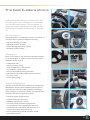
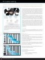
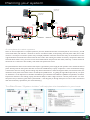
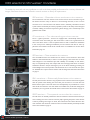
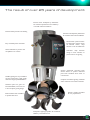
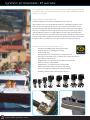
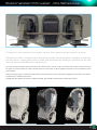
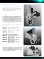
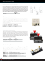
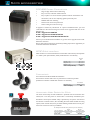
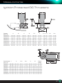
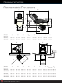
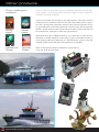
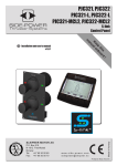
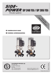
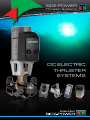
SIDE-POWER Thruster Systems DC ELECTRIC THRUSTER SYSTEMS Over 100 years of service 2008 marked Sleipner Motor’s 100th year serving the boating community. While our product development focuses on making boating easier, safer, more accessible comfortable, our historic commitment has always been to offer the highest quality and reliability to our customers. Over the years we have grown to be the global leader in thrusters (with well over 100,000 put into service) and we are proud to know that our products have enhanced the boating experience for so many people. It makes docking easy since 1908 "There are two types of boaters: those who have a bow thruster and those who wish they had one!" - Eric Vader World Boater INDEX Side-Power by Sleipner 2 The boat builder’s choice 3 Thruster sizing4 Planning your system 5 DC thruster models 6 Tunnel thrusters7 IP thrusters8 External stern thruster 9 Retractable thrusters 10 DC Speed Control 12 S-link control system 14 DC thruster range 16 Side-Power features 18 On/Off control panels 20 Stern thruster kits 21 Accessories22 S-link control panels 24 S-link accessories25 Measurements26 Other Side-Power products 30 www.side-power.com As marinas get more crowded and slips become tighter, docking a boat safely is more challenging than ever before. Thrusters give you total control of your boat and allow you to maneuver into and out of tight spots with ease and actual control of your boat. Thrusters also have the benefit over “pod” systems with single joystick that they only need to apply a reasonable amount of power in the actual direction you wish to move the boat, instead of having to use perhaps as much as ten times this power through vectoring several thrust sources to achieve a net power in the desired direction, thereby avoiding the annoying wash for all the boats around you. Confidence in all conditions Boating is meant to be fun. Why end your day or week on the water with a stressful experience? A Side-Power thruster offers the help you need to be in full control when docking and departing regardless of wind conditions and currents. And you can do this with full confidence, you do not need to rely on a computer to understand what you mean to do and then re-apply this into other commands to several propulsion sources. Using thrusters means you control exactly what is going to happen. Even simpler shorthanded boating With the new DC Speed control thrusters, the unique “Hold” function takes shorthanded boating to a new level. See page 8 for more information The boat builders choice Leading boat builders all over the world choose SidePower for performance, reliability, ease of installation and unrivalled safety features. This commitment to quality and product development has made the SidePower range of thrusters the benchmark in the industry. Performance The high performance of a Side-Power thruster is a result of our continuous efforts in product development and testing. •propulsion technology know-how •lightweight composite propellers •purpose-built high power electric motors •streamlined gearhouse design Installation Based on our experience and cooperation with major boatbuilders we have designed our systems to ensure it is easy to install a Side-Power thruster correctly. •compact-sized units •"Plug & Go" electric wiring •easily accessible battery cable terminals •easy installation of control panels •fast and safe propeller mounting with locknut •professional and solid GRP/composite stern thruster kits •easy access anodes •easy fit sealed gearlegs Safety & Reliability The safety of the boat and those on board is our utmost priority. All Side-Power thrusters include standard features that protect against operator errors and technical problems, minimizing potential consequences. Side-Power thrusters are purpose built for professional use with no compromise on quality. •overheat protection of electric motor •mechanical protection of drive gear •self-locking “high pressure” contacts •extra wear and heat protection of internal wires •non conductive and self extinguishing solenoid covers •control panels have child safe On/Off (instant On) and automatic deactivation timed from last use •in-house manufacturing, assembly and quality control •2-year limited warranty 3 Thruster sizing By definition, any thruster will to some extent do a job in any boat. The key is to ensure that the chosen thruster will do the job you want it to in your boat. This is one of two main factors deciding the right thruster size for each boat. Thruster model Thruster position A Thruster position B SE130/250T 21.2 kn 22.4 kn SE170/250TC 23.9 kn 25.2 kn The example above shows the different wind speeds that two different thruster installations can counter and the increased leverage gained when the thruster is positioned further forward. ELECTRIC THRUSTERS 6 Boat size: (m) 9 12 15 18 21 24 27 30 SE30 SE40 Ø 125mm SE60 SE80 SE100 Ø 185mm SE120 SE130 SE150 Ø 215mm SE130 SE170 SE210 Ø 250mm SP240TCi SP285TCi Ø 300mm Boat size: (ft) 20 30 40 HYDRAULIC THRUSTERS Boat size: (m) 9 12 15 18 50 21 60 24 27 70 30 80 33 90 36 39 100 42 Today most pleasure craft over 35’ have a bow thruster as standard equipment which normally will meet the expectations of most customers when using the boat under normal w eather conditions. The sizes used by the boat builders will vary depending on the boat’s intended usage and price level. In today’s production boats, the typical thruster will push the boat’s bow against a direct side wind of 21-23 knots. Some custom built or very high end boats may have a high power bow thruster that pushes the bow against a direct side wind of 2426 knots. For boat owners that use their boats in more demanding c onditions or have, for example, a strong current in their local marina, or for other reasons require very high performance, many boat builders offer upgrades to a more powerful thruster system. While most pleasure crafts will have ample power in most conditions when the thruster can push the bow against a direct side wind of 25-27 knots, this year’s addition of the “DC Speed Control” system will allow for even more powerful DC electric thrusters to be used comfortably. Charts The charts shown here are general guidelines and your dealer will be able to give more detailed advice on the thruster size to use for your boat. Example If you have a 45’/13.5m boat, you have 4 thrusters to choose from within “normal” sizing. If your boat does not have a lot of wind area and you use it mostly in good weather conditions, you can choose the least powerful thruster, the SE80 in a 185mm tunnel. If you want to keep the ø185mm tunnel dia, but require more power, the SE100 is a good choice. If you have room for a larger tunnel diameter, there are models in both ø215mm and ø250mm tunnels that are suitable for this boat size, so there are many options. 45 Please note that generally, a larger tunnel diameter will be more energy efficient and generate less noise. SH100 Ø 185mm SH160 SE100 Ø 215mm Conclusion SH240 The two main factors that decide correct thruster sizing are: Ø 250mm SP300HYD Ø 300mm SH420 • • SH550 Ø 386mm Boat size: (ft) 30 40 50 60 70 80 90 100 www.side-power.com 110 120 130 140 150 boat owner’s performance requirements boat size, type and shape Planning your system BOW 6 1278-xxM 5-LEAD CONTROL CABLE 6 1278-xxM 5-LEAD CONTROL CABLE STERN 6 1273 5-LEAD Y-CONNECTOR 6 1273 5-LEAD Y-CONNECTOR STERN Switch Switch 5A fuse 5A fuse BOW STERN 6 1278-xxM 5-LEAD CONTROL CABLE 6 1277-xxM 4-LEAD CONTROL CABLE 6 1278-xxM 5-LEAD CONTROL CABLE 6 1277-xxM 4-LEAD CONTROL CABLE A complete thruster system There are several components in a complete system for your boat; besides the thrusters and tunnels (bow or stern or both) – you will need control cables, main switches – automatic or manual – fuse & fuse- holder, control panel(s) and main power cables, even a radio remote is a normal part of a thruster system today. To simplify installation and further increase the safety, we recommend to use the original Side-Power Automatic Main switch which also has a built in fuse reducing the number of necessary components. Where the Automatic Main switch is used, you need a 5 lead control cable between the panel and main switch, while only a 4 lead is needed to the thruster or if a manual or other auxiliary main switch and separate fuse is used. The powerful electric motors used on the thrusters require a good electric power supply for safe operation and to achieve the desired power. Thereby, both the main power cable sizes as well as the available battery capacity is important. It is the actual delivered voltage at the thruster when it is running, after the voltage drop both in the batteries as well as through the cables, main switch and fuse, that decides the actual power of the electric motor and thereby the possible thrust. So, getting this right will be important for your product satisfaction. It is also important to remember that different types of batteries have different capabilities and specialties, and what is important for thrusters is the cranking capacity, the batteries ability to deliver a high current for a shorter period of time. On www. side-power.com you will find a guide called “system builder” – that will guide you through what parts to order as well as recommend cable sizes and battery capacities for your chosen thruster(s). The Side-Power “System builder” will help plan the installation in your boat. 5 DC electric thruster models To enable the most safe and easy installation as well as the best possible performance for a variety of boats and usages, Side-Power thrusters are offered in several versions to satisfy all requirements. SE series – Standard bow and stern thrusters The standard bow and stern thruster series are the base for all our extensive range of DC electric thrusters. They are fitted in a tunnel through the bow, or into our stern tunnels to use as a stern thrusters. The electric motors, solenoids, patented IPC control system and the mechanical parts of the propulsion system are all totally custom designed and built, utilizing the extensive experience gained through years of leadership in the global thruster market. IP versions – For demanding environments The IP – ignition protected – versions are equipped with a hermetically sealed cover around the motor and switch gear. This means that it is safe to use in gasoline boats or other areas where there is a risk of explosive fumes as well as excellent for installation in wet areas (not for submerged installation). Can be used for both bow or stern applications. Most models in both the SE and SEP series are available in IP versions. More information page 10. SR series – Retractable thrusters Our retractable thrusters are excellent for use as bow or stern thrusters in boats with shallow or flat bottomed hulls, or where a tunnel opening in the hull at all is not desirable. Designed in true Side-Power spirit with reliability and durability as main factors, they are exceptionally sturdy and compact with the same high performance as all other Side-Power thrusters. Unique advantages by use of the latest technology including our S-link intelligent bus control provides a further benefit in use and control for the operator. Available also as speed control versions with the designation SRP. More information on page 11. SX versions – Externally fitted stern thrusters. The fully external stern thrusters. Very popular for boats with twin stern drives together with the special cowls directing the water flow past the drives or in boats that have limited internal space in the back of the boat. Exceptionally easy installation is a bonus with the SX stern thrusters. Two size models are available now, the 80 and 100 kg thrust models and you can get both SE and SEP series in SX versions. More details on page 12. SEP series – The speed controlled thrusters The SEP series are basically SE thrusters with the addition of the DC Powercontrol system. Providing even more accurate control by fully regulating the power of the thruster as well as providing even longer run times, this is the latest in DC electric thrusters. The noise reduction and automatic ”Hold” function are further benefits provided by the SEP series. More details on page 14. www.side-power.com The result of over 25 years of development Electric motor developed by Side-Power for maximum performance and efficiency in real life onboard conditions Thermal switch prevents overheating Contactors developed by Side-Power for extended main solenoid lifetime Patented IPC system monitoring solenoids to reduce chance of solenoid lock-in, stops thruster in case of malfunction Easy accessable power terminals Closed solenoids to prevent dust and pollution on contacts Automatic delay between change in drive direction to protect motor and gearleg Gearleg galvanically separated from electro motor to protect immersed parts from accidental short circuit or current leaks Prefilled gearleg for easy installation and less maintenance. High quality oil for the longest possible lifetime Compact streamlined gearleg minimizes water resistance and reduces cavitation Hardened spiral cut gears for extended lifetime, low noise and a more compact gearleg design Anodes outside propellers for easy replacement CNC machined and assembled to perfect tolerances Composite Q-prop propellers for maximum efficiency and minimal noise 7 Ignition protected - IP series For several years, Side-Power has manufactured ignition protected thruster models. Now, the second generation is here with added features and many more models. High safety standards To provide reliable and safe thruster installations in more boats, we offer modified versions of our DC electric thrusters in watertight housings for use in stern and other locations that may get wet or be exposed to petrol fumes. These thrusters are fully ignition protected (ISO 8846) for use in boats with petrol engines. They have a hermetically sealed composite housing around all electric parts. This provides the ignition protection as no petrol fumes can enter and be ignited by sparks. The other advantage is that the electric parts that could be damaged by water are also covered and protected, making these thrusters the ideal choice for other stern thruster installations where it is difficult to ensure that the thruster will always remain dry. Ignition Protected Features • • • • • • • • www.side-power.com Certified to ISO 8846 Ignition Protected standards Water Proof (not for submerged mounting) Stainless cable seals Manufactured, tested and delivered as a ready sealed unit, ensuring that the installer does not have to fit any other parts that can jeopardize the hermetical seal Supplied with 1 m/3.28 ft main power cables and termination blocks for easy and safe installation Supplied with 1 m/3.28 ft plug and go control cable Ignition protected housing can be opened and thereby retains serviceability of components inside the enclosure Available as SEP-IP versions with DC Speed Control. External sternthruster - the SX series Finally a functional stern thruster option for boats with twin stern drives! Side-Power now offers a complete external sternthuster assembly, specially designed for installation on boats with twin stern drives. It utilizes special cowls to enable good performance by diverting the waterflow past the stern drive legs, which normally blocks the v and the thrust. The units come pre-assembled, wired and sealed in the waterproof box, and only require a small hole into the boat’s transom to attach the power and control cables. The cable connection points are fully sealed, so that it is Ignition Protected and can be installed in petrol powered boats. This stern thruster option can also be the best choice for boats without stern drives, if the inside configuration of the boat’s stern makes a standard thruster installation impractical. Available with two different size thrusters, SX80 and SX100. Also available in SXP versions with DC speed control. 9 Retractables - the SR/SRV series Retractable thrusters Some boats do not have the possibility to fit a tunnel thruster and thereby require a retractable thruster. Side-Power have designed a product range that address known weaknesses in retractable thrusters, namely the sturdiness, reliability and speed of the in-water propulsion parts to offer retractable thrusters in true Side-Power spirit with no compromise on safety and reliability. The retracting thrusters are generally built with the same high safety standards as all Side-Power products, and incorporate the important benefits introduced with the SE-series thrusters. Our focus on safety is a totally integral part of the product design so that everything from build quality to ease of installation is thought of to ensure long term reliability. There are two versions of the retractable thrusters, one model design for direct mold-in, and one designed to be mounted on a flange. The flange can be a mold-in base from Side-Power, or the boat builders can manufacture their own base in materials suited for their hulls or as part of their basic hull design. Specific Retracting thruster features • • • • • • • Plug and play S-Link two way communication control cable wiring Motor assembly rigid mounted on retract casing - no moving parts during retract operation Compact measures Reliable retract mechanism, avoids sticking Fast deployment time Easy to use control panel with status feedback from thruster Available as SRP versions with DC Speed Control. Direct mould-in version The retractable thrusters for direct mould-in are available in the following models: SR80/185T 80kg thrust, available for 12V and 24V SR100/185T 100kg thrust, available for 12V and 24V www.side-power.com Flange mounted version The flange mounted models have thruster unit in a casing that will be bolted to a base. This allows for easier installation in hulls made from different materials, as well as in series production where you do not need to mix laminating and engineering type jobs. The 185mm tunnel diameter thrusters uses one fast and powerful actuator, while the 250mm tunnel diameter models have two actuators to handle the increased forces with the same exceptionally fast deploy/ retract operation time. The unique design of the underwater mechanism with only a few, but very sturdy parts that all contribute to the stability of the moving assembly. The unit is also designed to keep the thruster as compact as possible while enabling the safe use of heavier motors on the more powerful units. The vertical installation of the motors also reduce the impact forces on the assembly in extreme waves compared to motors fitted at an angle. The flange mounted retractable thrusters are available in the following models: SRV80/185T 80kg thrust, available for 12V and 24V SRV100/185T 100kg thrust, available for 12V and 24V SR130/250T 130kg thrust, available for 12V and 24V SR170/250TC 170kg thrust, 24V SR210/250TC 210kg thrust, 24V Mould-in base (not included with thruster): SRF-185-GRP Mould in mounting base for 185mm SRV models - ISO Polyester SRF-185-GRV Mould in mounting base or 185mm SRV models - Vinylester SRF-250-GRP Mould in mounting base for 250mm SR models - ISO Polyester SRF-250-GRV Mould in mounting base for 250mm SR models - Vinylester Hydraulic version The 185mm SRV and the 250mm SR models are available in hydraulic versions for those who prefer this powering option for longer run times or in situations where the height of a DC electric version is too high (see measurements on page 28). 11 DC Speed Control Ultimate docking! With many boat customers now having had several boats with thrusters, their functional demand of their thruster system has increased so that many choose to upgrade to more powerful thrusters than standard and even request hydraulic thruster systems to ensure that run-time limitations in DC electric thrusters will not be a problem. However, very powerful single speed thrusters can, in light weather conditions, be a bit difficult to use as they push the boat too fast, and with the focus on living space in modern boats, often there just is no room for a hydraulic system. The solution is to fit the new Side-Power DC Speed Controller which enables proportional speed control of a DC electric thruster. By also controlling the thruster’s power, you get even more precise handling of the boat in all conditions. By also using an upgraded thruster size, you will about never need full power, which means that the usable run time is extended a lot, at around 50% load you can expect close to continuous usage being possible, normally then limited to battery power. greatly simplified troubleshooting for most issues ever seen with thrusters as it shows both actual voltage on the thruster as well as current draw. The extended runtime The Proportional is put to good use in the Hold-function incorporated in the new panels. With a single press of a button, the bow and stern thrusters will keep you alongside the docks. The amount of thrust applied can be adjusted, and in addition the bow and stern thruster can be individually synchronized to get a balanced sideways motion - making single handed docking very easy indeed! Joystick Control Panels features a Back-lit LCD display giving instant feedback to the user. System status, amount of thrust & direction of thrust as well as remaining run time and battery capacity will be shown in real time on the display. Important user warnings and alarms will be given to the user both on screen and via audible signals. The DC Speed Control system is controlled by S-link and monitors important parameters such as temperature in both controller and thruster as well as thruster voltage – this monitoring will also enable Even more functionality by adding a Side-Power radio remote! When a Side-Power radio remote is added to the system you get even more benefits from the speed control system. If you are docking alone - having the PJC panel automatically pushing the boat against the dock while you go put the mooring lines on, you might wish to increase the thrust on the bow thruster momentarily to make it really tight. Pressing the bow thruster button on the remote will then let you do this. You can also shut down the hold function without going to a fixed control panel by selecting to run any of the thrusters in opposite direction of what the hold function is doing. www.side-power.com System features A DC Speed Control system contains three main elements - proportional control panels, a power control unit and a DC electric thruster - all tied together with the new S-link control system. The thrusters used in a speed control system is almost identical to the familiar SE range of DC thrusters, the only difference being the addition of a temperature sensor and a new electronic control box. All mechanical and main electric parts are from the well proven thruster range produced by Side-Power for many years. All 12 & 24 volt DC electric thrusters produced by Side-Power can be enabled for DC Speed Control by authorized Side-Power service personnel, even the oldest models. PJC 212 Control Panel • • • • • • Plug and play S-link control cable wiring (waterproof plugs) Finger tip control with purpose designed joysticks Hold - function for easy docking, runs thrusters at selected power Back-lit LCD display with instant feedback - Amount of thrust & direction of thrust - Thruster temperature/remaining run time - Battery status - Selectable LCD colour & level for both night and day - System monitoring simplifies troubleshooting Interactive multilingual menus Built-in audible alarm “buzzer” PPC 800 Power Control Unit • • • • • • Plug and play S-link control cable wiring Easy to access, solid main cable terminals Easy to place as it can be located anywhere between the batteries and the thruster, also in areas requiring ignition protected parts Reliable solid state switching Thermal and over current protection Active cooling for continuous usage Thruster for DC Speed Control • • • • Any Side-Power DC Electric thruster can be upgraded to DC Power Control specification Temperature monitoring through PPC800 Increased directional solenoid lifetime because the solenoids will not switch with load IPC intelligence for extra safety “Easy does it with variable-speed thrusters” “...Until now the luxury of adjusting how much thrust you use to manoevre a big boat in or out of a tight spot has been the preserve of expensive and bulky hydraulic thruster systems. Sleipner’s new 12/24V system is a much more cost effective set-up and considerably more compact than a hydraulic system. It should also help resolve the issue of not being able to use an electronic thruster for long periods of time without overheating, because you‘ll rarely be using it on full power all the time...” “...Using conventional DC thrusters, offering full power or nothing, we would have had to apply numerous bursts to keep it rotating. With the variable-speed system we were able to use a smaller amount of continous thrust. Not only was this more intuitive, but it made for a quieter, more relaxed manoeuvre. The more power you want, the more you push the twin paddle switches...” “...This means that like a hydraulic system it also has a hold function, enabling you to set and leave the level of thrust. It’s a feature that shorthanded skippers often rely on to pin their boats against the dock while they step off to secure the lines...” “...The other big bonus is a remote control that allows you to operate both thrusters from wherever you chose, so you can take up station on the side deck and walk the boat in while keeping an eye on he gap...” MOTORBOAT & YACHTING - NOVEMBER 2010 13 S-link S-link System Wiring of S-link syste S-link is a ”CAN” based control system with full intelligent communication between all units in the system, much like a computer network. Explaining S-link Examp Wiring of S-link system S-linkof is aS-link ”CanBus” system based control - Round, compact andsystem waterproof plugs with unique keying and color coding Wiring Main advantages include: to avoid faulty hookup with full intelligent communication - Unlimited number of commands or information transfer on a single cable between all units in the system, much like - User feedback at panel Explaining S-link Example a computer network. - Intelligent troubleshooting Example of wiring of wiring S-link is a ”CanBus” based control system cable component overview Wiring of system Main advantages include: Wiring of S-link S-link system withS-link full intelligent communication compact and waterproof plugs with between all units in Round, the system, much like unique keying to avoid faulty hookup a S-link computer network. ggofof Unlimited number of commands or information S-linksystem system Example Example of of wiring wiring transfer on a single cable tem temMain advantages - include: Proprietary Sleipner commands, but built 100% Round, compact and waterproof with onof NMEA 2000plugs standard Example wiring Example of wiring unique keying to avoid faulty hookup h like like Unlimited number of commands or information transfer on a single cable Proprietary Sleipner commands, but built 100% Bow on Backbone cables thruster on NMEA 2000 standard Forms the main ”loop” around the boat with with 0% Bow thruster Bow thruster Automatic mainswitch S-link cable Automaticparts mainswitch Pow sup Power cable (sp Part #: 6 1320-xxM (xx=length) Must be one in each sy Automatic Power Control 0,2 m delivered in the length mainswitch supply panel 2,0 m rmation ormation Part #: 6 1328 4,0 m 7,0 m Backbone cables BACKBONE cables ilt 100% uilt 100% Bow Power Control Bow Automatic Power Control T-connector 15,0Automatic m Power cable (spur) Forms ”loop” around the boat Forms the the mainmain “loop” around the boat. 20,0 m thruster mainswitch supply panel thruster mainswitch supply panel Must be one for each s SPUR cables 6 1320-xxM (xx=length) Must be one in each system, PartPart #: 6#: 1320-xxM (xx=length) including Must be used to connect all parts tothe the power cab 0,2 m delivered in the length of 2,5m 6 1320-0,2M (0,2m) Part #: 6 1326 backbone cable ( one for each compo2,0 m Automatic Power Control Part #: 6 1328 6Automatic 1320-2M (2,0m) Spur cablesPower Control nent, no exeptions), recommended to 4,0(4,0m) m 6mainswitch 1320-4M mainswitch supply panel Must be used to connect all parts to the backbone cable (one for each component, no supply panel be as short as practically possible. 7,0(7,0m) m 6 1320-7M exeptions), recommended to besystem, as short as practically possible End terminator Must be one in each Part #: 6 1321-xxM (xx=length) 15,0 m T-connector 6 1320-15M (15,0m) Part #: 6delivered 1321-xxMin(xx=length) Must be one in each en the length of 2,5m 20,0 m 1321-0,4M Must be6one for each(0,4m) spur, 6 1320-20M (20,0m) 0,4 of the backbone ”loop” Power cable Power cable (spur) (spur) Part #: m 6 1328 6 1321-1M (1,0m) including the power cable 1,0 m one in each system, Must Must be be one in each system, (3,0m)Part #: 6 1327 Part #: 6 1321-3M 1326 3,0 m delivered delivered in in the the length length of of 2,5m 2,5m Spur cables 6 1321-5M (5,0m) 5,0#: m66 1328 Part #: 1328 cable (one for each component, no Must be used to connect all parts toPart the backbone S-link cable parts S-link cable parts Power cable (spur) S-link S-link cable cable parts parts le parts ble parts T-connector POWER cable Power cable (spur) Power cable (spur)to be2.5m exeptions), recommended as short practically possible Must be one in each system, length Must beasone for each spur, Must be #: oneone each system, Must in each system, Part 6 in 1321-xxM (xx=length) Part #: 6be 1328 including the power cable delivered in the length T-connector T-connector delivered in the of 2,5m 0,4length m of 2,5m Part #: 6 1326 Part #: 6 1328 Must Part #: 6 13281,0 m Must be be one one for for each each spur, spur, including including the the power power cable cable 3,0 m one for each component, no Part Part #: #: 66 1326 1326 BACKBONE EXTENDER 5,0 m ssible T-connector T-connector Connects two backbone cables to Must be one forfor each spur, for each component, no e cable cable (one (one for each component, no Must be one each spur, extend length. including thethe power cable cally cally possible possible including power cable Part #: 6 1322 Part #: #: 6 1326 Part 6 1326 End Endterminator terminator Must be be oneone in each endend Must in each of the backbone ”loop” of the backbone ”loop” Part #: #: 6 1327 Part 6 1327 End terminator Must be one in each end terminator End terminator of End the backbone ”loop” Must Must be be one one in in each each end end Part #: 6 1327 of of the the backbone backbone ”loop” ”loop” Part Part #: #: 66 1327 1327 www.side-power.com End terminator Must be one in each end of the backbone ”loop” T-CONNECTOR Part #: 1327for each spur, including Must be6one power cable. Part #: 6 1326 END TERMINATOR Must be one in each end of the backbone “loop”. Part #: 6 1327 CanBus control system Examples of the control wiring with S-link system for boats with two control positions and two DC proportional thrusters. Depending on the boat’s construction, there might be several different ways to route the S-link backbone. Find the most practical way to implement the backbone and remember that the S-link equipment do not need to be connected in a specific order. Example of the control wiring with S-link system for boats with one control position and one retractable thruster Example of the control wiring with S-link system for boats with one control position and two DC proportional retractable thrusters 2 x 6 1327 End terminators 7 x 6 1326 T-connectors 1 x 6 1328 Power spur 6 x 6 1320-xxM Backbone cables 6 x 6 1321-xxM Spur cables 2 x 6 1327 End terminators 4 x 6 1326 T-connectors 1 x 6 1328 Power spur 3 x 6 1320-xxM Backbone cables 3 x 6 1321-xxM Spur cables 2 x 6 1327 End terminators 6 x 6 1326 T-connectors 1 x 6 1328 Power spur 2 x 6 1320-xxM Backbone cables 5 x 6 1321-xxM Spur cables 15 DC thruster range SE Series thrusters SE 30/125 S SE 40/125 S SE 60/185 S SE 80/185 T SE 100/185 T SE 120/215 T Thrust at 10.5V/ 21V* Thrust at 12V/ 24V* (kg • lbs) Typical boat size (ft • m) Tunnel I.D. (mm • in) Propulsion system Power at 10.5V/ 21V* (kw • Hp) For DC system (V) Weight (kg • lbs) Min. Batt. Cap (CCA** 12/24V) 30 • 66 40 • 88 20’ - 28’ • 6 - 8.5 125 • 4.92’’ Single 1.5 • 2 12 9.5 • 21 200 40 • 88 48 • 105 26’ - 34’ • 8 - 10.5 125 • 4.92’’ Single 2.2 • 3 12 10 • 22 300 60 • 132 73 • 161 29’ - 38’ • 9 - 12 185 • 7.3’’ Single 3.1 • 4 12/24 16 • 35 350 • 175 80 • 176 96 • 212 35’ - 48’ • 10 - 15 185 • 7.3’’ Twin 4.4 • 6 12/24 20 • 44 550/300 100 • 220 116 • 256 35’ - 55’ • 12 - 17 185 • 7.3’’ Twin 6.3 • 8.4 12/24 31 • 68 750/400 120 • 264 139 • 306 42’ - 60’ • 13 - 18 215 • 8.46’’ Twin 6.4 • 8.55 24 34 • 74 400 Item Code 12V Item Code 24V SE30/125S(-IP) SE40/125S(-IP) SE60/185S-12V(-12IP) SE60/185S-24V(-24IP) SE80/185T-12V(-12IP) SE80/185T-24V(-24IP) SE100/185T-12V(-12IP) SE100/185T-24V(-24IP) SE120/215T (-IP) (kg • lbs) AVAILABLE AS SPEED CONTROL THRUSTERS * All Side-Power thrusters gets their thrust rating from the actual performance you can expect in a boat, at the voltage a normal installation will provide at the thruster. We have choosen to use the net performance at 10.5V/21V, but we also list the effect at 12V/24V for comparison. ** All Battery CCA Ratings are stated at the DIN Rating, multiply by 1.9 to equal the SAE rating at 0oF which is ABYC standard SX Series thrusters SX 80/185 T SX 100/185 T SR Series thrusters SR 80/185 T SR 100/185 T Thrust at 10.5V/ 21V* Thrust at 12V/ 24V* (kg • lbs) Typical boat size (ft • m) Tunnel I.D. (mm • in) Propulsion system Power at 10.5V/ 21V* (kw • Hp) For DC system (V) Weight (kg • lbs) Min. Batt. Cap (CCA** 12/24V) 80 • 176 96 • 212 35’ - 48’ • 10 - 15 185 • 7.3’’ Twin 4.4 • 6 12/24 52 • 115 550/300 100 • 220 116 • 256 35’ - 55’ • 12 - 17 185 • 7.3’’ Twin 6.3 • 8.4 12/24 57 • 125 750/400 Thrust at 10.5V/21V* Thrust at 12V/24V* (kg • lbs) Typical boat size (ft • m) Tunnel I.D. (mm • in) Propulsion system Power at 10.5V/21V* (kw • Hp) For DC system (V) Weight (kg • lbs) Min. Batt. Cap (CCA** 12/24V) 80 • 176 96 • 212 35’ - 48’ • 10 - 15 185 • 7.3’’ Twin 4.4 • 6 12/24 31 • 68 550/300 100 • 220 116 • 256 35’ - 55’ • 12 - 17 185 • 7.3’’ Twin 6.3 • 8.4 12/24 44 • 97 750/400 Item Code 12V Item Code 24V SX80/185T-12V SX80/185T-24V SX100/185T-12V SX100/185T-24V Item Code 12V Item Code 24V SR80/185T-12V SR80/185T-24V SR100/185T-12V SR100/185T-24V (kg • lbs) (kg • lbs) AVAILABLE AS SPEED CONTROL THRUSTERS www.side-power.com SE 130/250 T SE 150/215 T SE 170/250 TC SE 210/250 TC SP 240 TCi SP 285 TCi 285 • 627 340 • 748 74’ - 100’ • 22 - 30 300 • 11.8’’ Twin Counter rot. 15 • 20 24 (48V motor) 73 • 160 2x450 - 24V SP285TCi 130 • 284 160 • 352 42’ - 62’ • 13 - 19 250 • 9.8’’ Twin 6.5 • 8.7 12/24 37 • 77 750/400 150 • 330 182 • 400 44’ - 64’ • 14 - 20 215 • 8.46’’ Twin 8.8 • 11.8 24 38 • 79 560 170 • 374 210 • 462 50’ - 70’ • 15 - 22 250 • 9.8’’ Twin Counter rot. 8 • 10.7 24 44 • 97 550 210 • 462 250 • 550 55’ - 78’ • 17 - 24 250 • 9.8’’ Twin Counter rot. 10 • 13.15 24 68 • 150 650 240 • 528 300 • 660 60’ - 84’ • 18 - 25 300 • 11.8’’ Twin Counter rot. 11.4 • 15.5 24 70 • 154 700 SE130/250T-12V(-12IP) SE130/250T-24V(-24IP) SE150/215T SE170/250TC(-IP) SE210/250TC SP240TCi SRV 80/185 T SRV 100/185 T SR 130/250 T SR 170/250 TC SR 210/250 TC 80 • 176 96 • 212 35’ - 48’ • 10 - 15 185 • 7.3’’ Twin 4.4 • 6 12/24 31 • 68 550/300 100 • 220 116 • 256 35’ - 55’ • 12 - 17 185 • 7.3’’ Twin 6.3 • 8.4 12/24 44 • 97 750/400 130 • 284 160 • 352 42’ - 62’ • 13 - 19 250 • 9.8’’ Twin 6.5 • 8.7 12/24 82 • 181 500/250 170 • 374 210 • 462 50’ - 70’ • 15 - 22 250 • 9.8’’ Twin Counter rot. 8 • 10.7 24 88 • 194 550 210 • 462 250 • 550 55’ - 78’ • 17 - 24 250 • 9.8’’ Twin Counter rot. 11 • 14.5 24 112 • 247 650 SRV80/185T-12V SRV80/185T-24V SRV100/185T-12V SRV100/185T-24V SR130/250T-12V SR130/250T-24V SR170/250TC-24V SR210/250TC-24V 17 Side-Power FEATURES • Noise reductions of up to 75% measured in controlled environments • The expected and tested normal noise reduction in “average installations” 20-40% • Upgrade kits are available for most “SP” series thrusters with special adaptors • Provides delay between drive directions • Monitors solenoid functions to reduce the chance of solenoid lock-in • Will stop the thruster in case of a locked-in solenoid, without extra user action and even without controlling a main switch. The thruster gear leg is filled with oil from a remote reservoir located above the waterline. This generates overpressure, making an effective seal against water intrusion in the gear leg. • Separate oil reservoir placed above the waterline. • Allows easy access for oil changes • Having the advantage to be able to change oil in units used commercially, with hundreds of running hours per year. Sealed gear leg with long-life “mechanical” seal where highly polished ceramic and carbon surfaces form the only moving sealing surfaces, ensuring protection against damaging water intrusion into the gear leg. Pre-filled with special gear oil for lifetime lubrication. • “Mechanical” seals with surfaces of ceramic and carbon for ultimate security against water intrusion SINGLE PROPELLER: A properly engineered single propeller system will be the most energy efficient thruster. Its compact design fits easily into narrow bows making it the perfect match for our smaller models. With more than 60.000 single propeller thrusters in use, the Sidepower single series system has proven its reliability. TWIN PROPELLERS: The twin propeller system can give more thrust than a single propeller system in the same tunnel diameter. This is our choice for our mid-range models where high thrust is required in a small tunnel diameter. Due to the compact design and high performance, the twin models have become the thrusters of choice among boat builders around the world. TWIN COUNTER ROTATING PROPELLERS: Two counter-rotating propellers can give the most thrust at a good performance ratio in a minimal tunnel diameter. This system is used in our larger thrusters for maximum power. The TC models are the favourite thrusters among leading boatbuilders for their high-end yachts. ø 125 mm ø 185 mm ø 215 mm ø 250 mm ø 300 mm The gearhouse / drive legs of most Side-Power DC Electric thrusters are now fully galvanically isolated / separated from the electric motor and motor bracket. This ensures that even if there is an accidental short circuit or a current leak for other reasons, the immersed parts are not effected as they could be with direct electric contact. To provide reliable and safe thruster installations in more boats, we offer modified versions of our DC electric thrusters in watertight housings for use in stern and other locations that may get wet or be exposed to gasoline fumes. These thrusters are fully ignition protected (ISO 8846) for use in boats with gasoline engines. They have a hermetically sealed composite housing around all electric parts. This provides the ignition protection as no gasoline fumes can enter and be ignited by sparks. The other advantage is that the electric parts that could be damaged by water are also covered and protected, making these thrusters the ideal choice for other stern thruster installations where it is difficult to ensure that the thruster will always remain dry. S-LINK: S-link is a ”CAN” based control system with full intelligent communication between all units in the system, much like a computer network. Main advantages include: - Round, compact and waterproof plugs with unique keying and color coding to avoid faulty hookup - Unlimited number of commands or information transfer on a single cable - User feedback at panel - Intelligent troubleshooting. DC SPEED CONTROL: A DC Speed Control system contains three main elements proportional control panels, a power control unit and a DC electric thruster - all tied together with the new S-link control system. The thrusters used in a speed control system is almost identical to the familiar SE range of DC thrusters, the only difference being the addition of a temperature sensor and a new electronic control box. All mechanical and main electric parts are from the well proven thruster range produced by Side-Power for many years. All 12 & 24 volt DC electric thrusters produced by Side-Power can be enabled for DC Speed Control by authorized Side-Power service personnel, even the oldest models. With the ever growing demand for increased performance, we continue to expand our offering of tunnel diameters to allow customers to choose more powerful thrusters in tunnel sizes that will fit in their boat. The latest addition is the 215mm tunnel, between the existing ø185mm and ø250mm sizes. This size is very important for boat sizes around the 50’ / 15m mark, where we have seen that boats have become much more voluminous than before, requiring larger thrusters to achieve the same maneuverability. We will continue to launch new tunnel diameters where appropriate to let our customers get the performance they want in their boats. Facts about tunnel sizes: • Principally a larger tunnel diameter will always be more energy efficient than a smaller tunnel diameter for the same thrust. The factor is water speed, and this is decided by the amount of water you move through the possible opening which is the square area of the tunnel less the area blocked by the thrusters gearleg. • The opening in the boat hull is not only the circular size of the tunnel diameter. Because the hull is angled, you get a much larger oval opening, and this makes a larger tunnel diameter more difficult to fit properly into the hull. www.side-power.com Control panels with child safe on/off and time lapse auto-off prevent accidental or unintentional o peration P Self re-setting overheat protection automatically stops the thruster before overheating PP Intelligent direction change delay simplifies operation and prevents damage from operator error PP Control system only accepts continuous run signal for 3 min. User warning before overheat protection activates PP Side-Power developed special solenoid c ontactors ensures correct function and maximum lifetime in a boat PPP Closed solenoid contacts prevent dust from getting into the contacts PPP External main power terminals ensure fast, easy and safe connection of heavy power cables GRP tunnels are purpose built for thruster applications, they are precise, strong, and protected against o smosis easy service easy installation better performance lifetime & reliability safety The difference is in the details P PP PPP Lightweight composite propellers on all thrusters are strong yet lightweight, and always perfectly shaped for high power and low noise PP Lock nut fastening of propellers provides easy and reliable fitting of the propellers PPP All panels, thrusters and accessories have "Plug & Go" wiring for easy, correct and reliable wiring PPP Anodes outside propellers make them easy to access and change without having to remove propellers PPP Electromotors designed and rated for actual voltage in boat ensures correct performance and e fficiency in real life conditions PP Oil filled gearleg with long life special seals ensures a long, trouble free lifetime of the thruster P P Hardened spiral-cut gears give you extended lifetime, low noise and more compact gearhouse design PP All bearing and sealing surfaces machined in CNC machines ensures correct tolerances, surfaces and angles PP Slim, hydrodynamically shaped gearlegs minimize resistance and possibility for c avitation P Galvanic isolation of underwater parts remove chance of serious failure due to current leaks or accidental short circuits PP Intelligent Power Control (IPC) automatically safeguards against inherent risks in high-current equipment. PPPP 19 Control panels for DC thrusters Side-Power offers a unique series of «smart» control panels, an important part of a thruster system. Choose between our compact touch button, the popular joystick controls, the «docking» control panel with the most intuitive thruster control ever or the new exclusive round panel. Why not try the radio remote control for full mobility onboard, being the perfect tool for shorthanded boating. Radio linked panels are also an option. Mix or match, the choice is yours! Easy installation Safety Quality Design •round cut-out hole (std.instrument size) •installs from front side •pre-fitted O-ring seal •multi-voltage (12 & 24V) •child-safe on / off system •power / control light •automatic deactivation •easy operation •waterproof (IP65-front) •UV safe •CE -approved •compact size •modern styling •no visible screw heads 8950 G 8955 8960 G 8965 8940 G 8909 C Control Panel Touch panel Round touch panel Joystick panel, grey Joystick panel, black Boat switch panel Item code 8950 G 8955 G 8960 G 8960 S 8965 H (mm) 70 ø 86,5 70 70 ø 86,5 W (mm) 70 70 70 - No. thrusters 1 1 1 1 1 Dual joystick panel, grey Dual joystick panel, black Docking panel 8940 G 8940 S 8909 C 120 120 120 70 70 70 2 2 2 Handheld radio remotes A radio remote control makes your thruster system even more helpful around the docks. Providing full simultaneous control of a bow and a stern thruster or a bow thruster and a windlass, making shorthanded boating much easier. New and upgraded model autumn 2012 Side-Power is now releasing a new and improved version of the radio remote control. The new transmitter is black with an opaque frame around the buttons, and the receiver is designed with a new exernal antenna. Changes in the new model: • The remote transmitter now features visual and audible alarms. • Warning/alert given when the transmitter have no contact with the receiver and when the thruster supply voltage is to low. • Dedicated version for S-link thrusters (8730 interface no longer required). • New external antenna solution for better reception and easier remote placement of the antenna (Extension cable available). • More energy efficient transmitter- uses only one battery, maintains operating time from earlier model with two batteries. Radio remotes H (mm • in) 95 • 3.74 (transmitter) W (mm • in) 48 • 1.89 (transmitter) Item code: Radio remote set (bow + stern thruster) / Radio remote set (bow thruster + windlass) RC-10E/RC-11E Extra transmitter (bow + stern thruster) / Extra transmitter (bow thruster + windlass) RCT-10E/RCT-11E www.side-power.com Tunnels and stern thruster kits Tunnels GRP tunnels are available in several lengths for each thruster model. They are purpose built for our thrusters and provide ultimate strength, accuracy and osmosis protection to ensure an easy and safe thruster installation. The wall thickness is adapted to each thruster's power and boat size. We also offer a selection of aluminium and steel tunnels. Stern thruster kits These transom-mounted tunnels are meticulously designed to enhance the performance of the thruster. Manufactured in fibreglass, they are extremely strong and durable. The complete installation is very easy and meets the high Side-Power standards. The additional cowls make it possible to allow a stern thruster installation in boats with shallow draft or obstructions on the stern. INJECTION MOULD STERN TUNNEL KIT 90150i Tunnel halves snaps together after mounting gearleg/ propellers Groves for application of sealant Extra metal support brackets Injection mould stern tunnels Injection mould tunnels with extra safety features; 30% stronger and specific breaking point design. Available for 125mm, 185mm and 250mm tunnel diameter thrusters. The new 250mm tunnel features split tunnel assembly for easier installation and integrated support for thruster motor and bracket, eliminating the need for an external support strut. Integrated support struts for each of the 4 motor bracket legs The combination of metal brackets and support struts eliminates the need for a separate support for the motor inside the boat Stern tunnels & cowls: Item code Stern thruster kit Cowls - short model Cowls - long model Item code Stern thruster kit Cowls - short model Cowls - long model SE 130/170 SE130/170 SE210 SP 240 / 285 90140i 90150i90150i 90200i – – – - 90132 9013290132 90220 Item code Stern thruster kit Cowls - short model Cowls - long model SH 100 SH 160 SH 240 SP300HYD SH 420/550 90086i 90135i90140i/90150i 90200i 90550 90075- - – 90077 90136 90132 9022090560 SE 30/40 90124i - 90126 SE 60 SE 80/100 SE 120/150 90052i 90086i 90135i 9007590075 90077 90077 90136 21 Accessories Radio link for control panels The radio link eliminates the need for difficult cable runs between control panel(s) and thruster. Consisting of a transmitter box, that connects to a control panel and a remote control receiver that plugs into the thruster(s), the receiver accepts up to 4 independent transmitters or hand held radio remotes. The multi-channel system supports two thrusters and can be mixed with hard wired control panels. Full Side-Power safety level with child-safe activation and intelligent auto-off, even at the receiver. Radio link kit Extra transmitter unit for radio link kit Item codes: 8970 8975 Serial-parallel switch box This switch box enables the installation of 24V thrusters in b oats with a 12V system. With an additional 12V battery, you s upply 24V for the thruster’s operation, while all batteries are charged by your normal 12V system when the thruster is not running. The reliability of this fully automatic system has been proven in h undreds of boats over many years. To install 24V thrusters in 12V boats (necessary extra battery is not included) For SE 120/130/150/170 For SE200/SP240 H x W x D (mm) 285 x 265 x 110 285 x 265 x 110 H x W x D (in) 11.2 x 10.4 x 4.3 11.2 x 10.4 x 4.3 Item code 10112A 15112A Automatic main switch The most user friendly and safe installation is provided with the automatic main switch/fuse. The main power to the thruster is conveniently controlled by the Side-Power control panel. Added safety is provided by the panel's auto-off and the thruster’s overheat sensor, also controlling the main switch. Flexible mounting options, "Plug & Go" wiring, heavy terminals allowing double cables and only one item to fit ensures fast and easy installation. For Side-Power thrusters (necessary fuse not included) 12 Volt 24 Volt H x W x D (mm) 175 x 205 x 140 175 x 205 x 140 H x W x D (in) 6.9 x 8.1 x 5.5 6.9 x 8.1 x 5.5 Item code 897612 897624 Fuse holder / Fuses Side-Power manufactures fuse holders that are engineered to minimize voltage drop and heating while saving space. Made for ANL type fuses in high current applications, they accept double cables with heavyterminals. The fuse holder is also available with a protective c over. We supply ANL fuses in s izes to match all of our thrusters. Item code Fuse ANL150 150A ANL250 250A ANL325 325A ANL400 400A ANL500 500A ANLHOLD ANLHOLD-C For thruster SE30/125S - SE60/185S-24V SE40/125S - SE60/185S-12 - SE80/185T-24 SE100/185T-24 - SE120/215T-24 - SE130/250T-24 - SP285TCi SE80/185T-12 - SE150/215T-24 - SE170/250TC SE100/185T-12 - SE130/250T-12 - SE210/250TC - SP240TCi Fuseholder for all ANL type fuses Fuseholder including clear cover www.side-power.com Control cables Make sure that the complete installation meets the Side-Power q uality standard and take advantage of our "Plug & Go" wiring system by using original control looms. They are available in many different lengths and Y-connectors tie multiple control positions together. Colour coded to match the wiring diagrams with high q uality connectors to ensure a correct installation. 4-Lead control cables Item code 6 1277-04M 6 1277-07M 6 1277-09M 6 1277-12M 6 1277-15M 6 1277-18M 6 1277-22M 6 1274 Description Control cable 4 meter, 4-lead Control cable 7 meter, 4-lead Control cable 9 meter, 4-lead Control cable 12 meter, 4-lead Control cable 15 meter, 4-lead Control cable 18 meter, 4-lead Control cable 22 meter, 4-lead Y-connector for multiple control panels, 4-lead 5-Lead control cables, for systems with automatic main switch Item code 6 1278-04M 6 1278-07M 6 1278-09M 6 1278-12M 6 1278-15M 6 1278-18M 6 1278-22M 6 1273 Description Control cable 4 meter, 5-lead Control cable 7 meter, 5-lead Control cable 9 meter, 5-lead Control cable 12 meter, 5-lead Control cable 15 meter, 5-lead Control cable 18 meter, 5-lead Control cable 22 meter, 5-lead Y-connector for multiple control panels, 5-lead Control cable wiring example BOW 6 1278-xxM 5-LEAD CONTROL CABLE 6 1278-xxM 5-LEAD CONTROL CABLE STERN 6 1273 5-LEAD Y-CONNECTOR 6 1273 5-LEAD Y-CONNECTOR STERN BOW STERN 6 1278-xxM 5-LEAD CONTROL CABLE 6 1277-xxM 4-LEAD CONTROL CABLE 6 1278-xxM 5-LEAD CONTROL CABLE 6 1277-xxM 4-LEAD CONTROL CABLE 23 Control panels for S-link systems PJC 212 Dual Joystick for DC Speed Control • • • • • • • • • • Finger tip control with purpose designed joysticks Hold - function for easy docking, runs thrusters at selected power Back-lit LCD display with instant feedback - System status - Amount of thrust & direction of thrust - Thruster temperature/remaining run time - Battery status Interactive multi-language menus System setup via “wizard” Diagnostics via panel/computer interface Built-in audible alarm “buzzer” Connector for external “buzzer”/loud audible alarms Also available for hydraulic systems Can be used as ON/OFF panel with SR retractable thrusters Dual Joystick H (mm • in) 141 • 5.55 W (mm • in) 83 • 3.27 Item code (12 & 24V) PJC212 PJC 211 Single Joystick for DC Speed Control • Same as PJC212, but for one thruster - without hold function. Singel Joystick H (mm • in) 141 • 5.55 W (mm • in) 83 • 3.27 Item code (12 & 24V) PJC211 8900 S-link Touch Panel for retract thrusters The compact and flush design keeps smaller dashboards tidy and prevents ropes from snagging on sailboats. LED status indicators reports the status of the SR thruster via S-link, as well as clear and direct service notices. Touch panel H (mm • in) 70 • 2.76 W (mm • in) 70 • 2.76 Item code (12 & 24V) 8700 S-link Handheld radio remotes A radio remote control makes your thruster system even more helpful around the docks. Providing full simultaneous control of a bow and a stern thruster or a bow thruster and a windlass, making shorthanded boating much easier. Changes in the new model: • The remote transmitter features visual and audible alarms. • Warning/alert given when the transmitter have no contact with the receiver and when the thruster supply voltage is to low. • Dedicated version for S-link thrusters (8730 interface no longer required). • New external antenna solution for better reception and easier remote placement of the antenna (Extension cable available). • More energy efficient transmitter- uses only one battery, maintains operating time from earlier model with two batteries. Radio remotes H (mm • in) 95 • 3.74 (transmitter) W (mm • in) 48 • 1.89 (transmitter) Item code: Radio remote set (bow + stern thruster) / Radio remote set (bow thruster + windlass) RCS-10E/RCS-11E Extra transmitter (bow + stern thruster) / Extra transmitter (bow thruster + windlass) RCT-10E/RCT-11E www.side-power.com S-link accessories PPC 800 Power Control Unit • • • • • • Plug and play S-link control cable wiring Easy to access, solid main cable terminals Easy to place as it can be located anywhere between the batteries and the thruster, also in areas requiring ignition protected parts Reliable solid state switching Thermal and overcurrent protection Active cooling for continuous usage To upgrade a standard on/off thruster to a speed controlled thruster, you need a PPC 800 and the internal wiring loom needs to be upgraded with one of the following kits: 8 1997 - Upgrade kit SR80/100 8 1998 - Upgrade kit SE100/120/210/240 8 1999 - Upgrade kit SE30/40/60/80/130/150/170 Contact your local Side-Power distributor to get the correct upgrade kit for older Side-Power thrusters. Due to their sealed construction, IP-models (including SX) must be upgraded by an authorized Side-Power Distributor! 8730 S-link Interface S-link interface to connect footswitches and standard radio remotes/control panels to a S-link system (Footswitches/Panels/Radio Remote not included). Interface Box H (mm • in) 45 • 1.77 W (mm • in) 80 • 3.15 D (mm • in) 145 • 5.70 Item code (12 & 24V) 8730 Foot switch Foot switch kit suitable for 8730 S-link interface. Kit contains 2 switches with covers to protect from unwanted operation. (Cables from switches to 8730 S-link interface not included) Foot Switch W (mm • in) Ø105 • 4.13 Item code (Kit) 8751 Automatic Main Switch for S-link The most user friendly and safe installation is provided with the automatic main switch/fuse. The main power to the thruster is conveniently controlled by the Side-Power control panel. Added safety is provided by the panel’s auto-off and the thruster’s overheat sensor, also controlling the main switch. Flexible mounting options, S-link control cable, heavy terminals allowing double c ables and only one item to fit ensures fast and easy installation. For SidepowerS-link thrusters (necessary fuse not included) 12 Volt 24 Volt H x W x D (mm) 175 x 205 x 140 175 x 205 x 140 H x W x D (in) 6.9 x 8.1 x 5.5 6.9 x 8.1 x 5.5 Item code 897712 897724 25 Measurements DC Thrusters D C WATERLINE WATERLINE B E E A A G G F ThrusterA B C D Emin (mm • in) SE30/125S 125 • 4.92 234 • 9.2 190 • 7.5 180 • 7.1 SE40/125S 125 • 4.92 234 • 9.2 190 • 7.5 180 • 7.1 SE60/185S 185 • 7.3 265 • 10.4 208 • 8.2 197 • 7.8 125 • 4.9 FFrecommendedGminGmax 92 • 3.6 184 • 7.25 4 • 0.16 5 • 0.20 125 • 4.9 92 • 3.6 184 • 7.25 4 • 0.16 5 • 0.20 150 • 5.9 117 • 4.6 234 • 9.2 4 • 0.16 6 • 0.24 SE80/185S 185 • 7.3 361 • 14.2 208 • 8.2 200 • 7.9 200 • 79 170 • 6.7 340 • 13.4 6 • 0.24 8 • 0.31 SE100/185T 185 • 7.3 389 • 15.3 245 • 9.6 245 • 9.6 200 • 7.9 170 • 6.7 340 • 13.4 6 • 0.24 8 • 0.31 SE120/215T 215 • 8.46 389 • 15.3 245 • 9.6 250 • 9.8 215 • 8.5 280 • 11.0 560 • 22.0 6 • 0.24 8 • 0.31 SE130/250T 250 • 9.84 398 • 15.7 254 • 10.0 256 • 10.1 230 • 9.0 280 • 11.0 560 • 22.0 7 • 0.28 10 • 0.39 SE150/215T 215 • 8.46 398 • 15.7 254 • 10.0 260 • 10.2 230 • 9.0 280 • 11.0 560 • 22.0 7 • 0.28 10 • 0.39 SE170/250TC 250 • 9.84 421 • 16.6 230 • 9.1 256 • 10.1 250 • 9.8 300 • 11.8 600 • 23.6 7 • 0.28 10 • 0.39 SE210/250TC 250 • 9.84 478 • 18.8 260 • 10.2 281 • 7.5 250 • 9.8 300 • 11.8 600 • 23.6 7 • 0.28 13 • 0.51 SP240TCi 300 • 11.81 490 • 19.3 266 • 10.5 296 • 11.7 300 • 11.8 300 • 11.8 600 • 23.6 10 • 0.39 13 • 0.51 SP285TCi 300 • 11.81 455 • 17.9 270 • 10,6 310 • 12.2 300 • 11.8 300 • 11.8 600 • 23.6 10 • 0.39 13 • 0.51 Stern thruster I II IIIminIVmax V VI Tunnel (mm • in) Length SE30/125S 196 • 7.72 190 • 7.48 135 • 5.31 14 • 0.55 160 • 6.3 217 • 8.5 197 • 7.76 SE40/125S 196 • 7.72 190 • 7.48 135 • 5.31 14 • 0.55 160 • 6.3 217 • 8.5 197 • 7.76 SE60/185S 225 • 8.90 256 • 10.1 150 • 5.91 35 • 1.38 200 • 7.8300 • 11.8 337 • 13.27 SE80/185S 321 • 13.7 256 • 10.1 200 • 7.87 54 • 2.13 200 • 7.8 300 • 11.8 337 • 13.27 SE100/185T 349 • 4.92 256 • 10.1 200 • 7.87 54 • 2.13 200 • 7.8300 • 11.8 337 • 13.27 SE120/215T 349 • 4.92 300 • 11.8 215 • 8.46 54 • 2.13 200 • 7.8300 • 11.8 330 • 13.0 SE130/250T 359 • 14.13 340 • 13.4 250 • 9.84 60 • 2.36 200 • 7.8350 • 11.8 350 • 13.87 SE150/215T 359 • 14.13 300 • 11.8 215 • 8.46 54 • 2.13 200 • 7.8350 • 13.8 330 • 13.0 SE170/250TC 382 • 15.04 340 • 13.4 250 • 9.84 60 • 2.36 200 • 7.8350 • 13.8 350 • 13.87 SE210/250TC 420 • 46.54 360 • 14.2 300 • 11.81 50 • 1.97 200 • 7.8 350 • 13.8 350 • 13.87 SP240TCi 441 • 17.36 420 • 16.5 300 • 11.81 60 • 2.36 258 • 10.2 396 • 15.6 456 • 17.95 SP285TCi 406 • 15.98 420 • 16.5 300 • 11.81 60 • 2.36 258 • 10.2 396 • 15.6 456 • 17.95 www.side-power.com WATERLINE IV max III II V VI I Measurements Ignition Protected DC Thrusters Thruster (mm • in) A B C DEmin SE30/125S IP 125 • 4.92 245 • 9.6 226 • 8.9 230 • 9.1 SE40/125S IP 125 • 4.92 245 • 9.6 226 • 8.9 230 • 9.1 SE60/185S IP 185 • 7.3 270 • 10.6 230 • 9.1 272 • 10.7 125 • 4.92 FFrecommendedGminGmax 92 • 3.6 184 • 7.25 4 • 0.16 5 • 0.20 125 • 4.92 92 • 3.6 184 • 7.25 4 • 0.16 5 • 0.20 150 • 5.91 117 • 4.6 234 • 9.2 4 • 0.16 6 • 0.24 SE80/185S IP 185 • 7.3 376 • 14.8 262 • 10.3 327 • 12.9 200 • 7.87 170 • 6.7 340 • 13.4 6 • 0.24 8 • 0.31 SE100/185T IP 185 • 7.3 451 • 17.8 308 • 12.1 382 • 15.0 200 • 7.87 170 • 6.7 340 • 13.4 6 • 0.24 8 • 0.31 SE120/215T IP 215 • 8.46 451 • 17.8 308 • 12.1 382 • 15.0 215 • 8.46 280 • 11 560 • 22.0 6 • 0.24 8 • 0.31 SE130/250T IP 250 • 9.84 451 • 17.8 308 • 12.1 382 • 15.0 230 • 9.00 280 • 11 560 • 22.0 7 • 0.28 10 • 0.39 SE170/250TC IP 250 • 9.84 451 • 17.8 308 • 12.1 382 • 15.0 250 • 9.84 300 • 11.8 600 • 23.6 7 • 0.28 10 • 0.39 V VI Stern thruster I II IIIminIVmax VVI Tunnel (mm • in) Length SE30/125S 220 • 8.66 190 • 7.48 14 • 0.55 160 • 6.3 217 • 8.5 197 • 7.76 SE40/125S 220 • 8.66 190 • 7.48 135 • 5.31 14 • 0.55 135 • 5.1 160 • 6.3 217 • 8.5 197 • 7.76 SE60/185S 265 • 10.43 256 • 10.1 150 • 5.91 35 • 1.38 200 • 7.8300 • 11.8 337 • 13.27 SE80/185S 399 • 15.70 256 • 10.1 200 • 7.87 54 • 2.13 200 • 7.8300 • 11.8 337 • 13.27 SE100/185T 407 • 16.02 256 • 10.1 200 • 7.87 44 • 1,73 200 • 7.8300 • 11.8 337 • 13.27 SE120/215T 407 • 16.02 300 • 11.8 215 • 8.46 44 • 1.73 200 • 7.8300 • 11.8 330 • 13.00 SE130/250T 407 • 16.02 340 • 13.4 250 • 9.84 60 • 2.36 200 • 7.8350 • 13.8 350 • 13.87 SE170/250TC 407 • 16.02 340 • 13.4 250 • 9.84 60 • 2.36 200 • 7.8350 • 13.8 350 • 13.87 27 Measurements Measurements, thruster GB Målskisse, truster N Retractable Thrusters E A D B WATERLINE G D E H C A SR80/185T F Thruster A B CDminE (mm • in) G F 335 • 13.2 413 • 16.3 SR100/185T 335 • 13.2 460 • 18.1 185 • 7.3 716 • 28.2 450 • 17.7 245 • 9,6 185 • 7.3 745 • 29.3 450 • 17.7 H 245 • 9,6 218 • 8.6 92 • 3.6 218 • 8.6 92 • 3.6 E B G SR80/185T D G WATERLINE E SR100/185T C D A SR80/185T - SR100/185T 1.1.0 - 2010 ThrusterA B C D E (mm • in) F F H G 3 A GG(w. Hyd. motor) Hmin SRV80/185T 416 • 16.4 564 • 22.2 Ø185 • 7.3 335 • 13.2 333 • 13.1 234 • 9.2 500 • 19.7 353 • 13.9 185 • 7.3 SRV100/185T 416 • 16.4 564 • 22.2 Ø185 • 7.3 335 • 13.2 333 • 13.1 234 • 9.2 528 • 20.8 353 • 13.9 185 • 7.3 SR130/250T 500 • 19.7 688 • 27.1 Ø250 • 9.8 395 • 15.6 480 • 18.9 370 • 14.7 594 • 23.4 482 • 19.0 250 • 9.8 SR170/250TC 500 • 19.7 688 • 27.1 Ø250 • 9.8 395 • 15.6 480 • 18.9 370 • 14.7 609 • 24.0 482 • 19.0 250 • 9.8 SR210/250TC 500 • 19.7 688 • 27.1 Ø250 • 9.8 395 • 15.6 480 • 18.9 370 • 14.7 694 • 27.3 482 • 19.0 250 • 9.8 www.side-power.com Max. use: Safety: S2 = 3 min. or appr. 7-10% within a limited time frame. All electromotors are protected against overheating. Electronic time-lapse device protects against sudden change of drive direction. Electric thermal cut-off switch in electromotor protects against over heating (auto reset when electro motor cools down). Flexible coupling between electro-motor and driveshaft protects electromotor and gearsystem if propeller gets jammed. If original Sidepower panel is used, the panel shuts off automatically 6 minutes after last use. Integrated microprocessor monitors solenoids, reducing wear and risk of solenoid lock-in. Auto-stop of thruster in case of accidental solenoid lock-in or if run signal is continous for more than 3 minutes. Measurements External stern thruster 115 314 567 296 ø140 253 91 439 25 ø1 85 Max. stern thickness: 100mm (80mm recommended) SX80/185T & SX100/185T External sternthruster assembly B Accessories Measurements Touch panel 8950G Single joystick panel 8960G S-linkTouch panel 8700 PPC 800 PJC 211/212/221/222 190 H:70mm W:70mm 178,6 Dual joystick panel 8940G Docking panel 8909 H:120mm W:70mm Ø:86.5mm 120 Round touch panel 8955G Boat switch panel 8965G 300 Ø3,5 (wood) Ø4 (GRP) 4X 2 1.1 - 2010 B+ M- B- Depth: 140mm 29 Other products Other catalogues available: Steering Systems Stabilizer Systems SIDE-POWER Larger thruster models and extended run time make hydraulic or AC electric thrusters the ideal choice for commercial crafts and other less maneuverable yachts. In conjunction with a good hydraulic system these thrusters o ffer continuous operation and you can get variable speed control with proportional control and valves. The last generation hydraulic and AC electric thruster systems features the S-link control system with two way communication, opening for a whole new range of features. With models from 100 to 1400kg of thrust for use as either bow or stern thrusters, Side-Power has suitable models for a wide variety of yachts and commercial v essels. To ensure matching quality of all components in a hydraulic thruster system, we also offer complete h ydraulic systems with guaranteed performance and reliability. Thruster Systems HYDRAULIC & AC ELECTRIC THRUSTER SYSTEMS Hydraulic & AC Thrusters There is a limit to the power you can practically generate with DC electrical systems, so for super yachts and other larger, heavier vessels DC thrusters are rarely an option. Superyacht Products www.side-power.com Please see the separate hydraulic and AC electric system brochure or ask your dealer for more details. Thrusters - Stabilizers - Steering Hydraulic thruster systems For many vessels, a hydraulic system offers an economic advantage because of the possibility to run several systems onboard from a c entralized hydraulic power source. This will save cost on the individual components so that the complete package ends up with a more favorable cost compared to running all items with individual DC electric motors. Equipment that is often powered by a centralized hydraulic system includes windlasses, stabilizers, winches, cranes, furling systems and lifting mechanisms etc. There are many different ways of designing hydraulic systems, and some solutions are better for specific applications than others. Side-Power hydraulic systems are designed to provide outstanding performance and flexibility to efficiently support any on-board hydraulic equipment that is sensible to power from a centralized hydraulic system. AC electric thruster systems The new thrusters in the SH and the SAC range are part of a total yacht control system. All of the Side-Power systems communicate on a shared CAN-Bus based S-Link system. The S-Link system enables the best integration possible no matter what the combination of equipment. AC Thrusters can be combined with hydraulic stabilizers. An AC bow thruster can be used with a hydraulic stern thruster and, in fact, any combination of Side-Power equipment imaginable can be used. Stabilizer systems • Increased comfort on board - More use of the boat as you can go out in more weather conditions - Less wear and tear of the boat as you do not have to always head into or away from larger waves to avoid people onboard becoming seasick by the uncomfortable rolling motion • Less overall fuel consumption - While adding fins (or other types) basically will increasing the fuel consumption a little at the same speed, our claim is that the overall fuel consumption will be reduced - You can take the direct route to where you wish to go even in rough conditions - You can go at a lower speed with the waves from the side while still being comfortable (modern cruisers have less roll at higher speeds, thereby people often drive them hard to avoid the rolling) Steering systems In addition to traditional hydraulic steering systems and electro-hydraulic power steering systems, Side-Power has also developed a Superyacht-specific steering system. While designing this, we have been able to draw from almost 100 years of experience with steering systems, and from our extensive knowledge on hydraulic systems. The Side-Power Superyacht Steering is a RINA-classed system which fills all demands to a commercial grade steering system. The Superyacht steering control system is a “fly-by-wire” system based around the same Slink bus as the Thruster and Stabilizer systems - the difference is that in the Steering System everything is made with dual configurations, to meet the required redundancy level. This dual configuration extends to the mechanical and hydraulic side of the system as well. The Superyacht Steering can be operated from a traditional helm or by joystick and the system is ready for autopilot interfacing. 31 Sleipner Motor AS P.O. Box 519, N-1612 Fredrikstad Norway Tel: +47 69 30 00 60 Fax: +47 69 30 00 70 Worldwide sales and service w w w. s i d e - p owe r. c o m All Side-Power products fulfill the requirements of the relevant CE-directives. SIDE-POWER THRUSTER SYSTEMS Sleipner Motor AS constantly seek ways of improving specifications, design and p roduction. Thus, alterations take place continuously. Whilst every effort is made to produce up-to-date literature, this brochure should not be regarded as a definitive guide to current specifications, nor does it constitute an offer for the sale of any particular product.