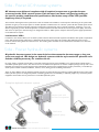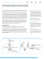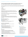
1
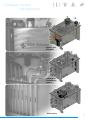
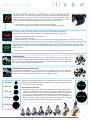
Hydraulic & AC Electric Thruster Systems Side - Power AC thruster systems AC thrusters are delivered complete with all required components to get the thruster connected to the S-link control system. Each thruster have been configured according to the specific working conditions and specifications. No further setup of the VFD (variable frequency drive) is required. The innovative S-link digital control system ensures fast and trouble free installation, and incorporates monitoring of the system while operated and gives you the unique option to combine hydraulic and AC thrusters in a thruster system. All with variable speed control. The SAC series is manufactured taking advantage of experiences gained though years of volume production, resulting in a very cost efficient, high quality product. All AC components are selected from brand name manufacturers ensuring the best quality and worldwide access to spare parts. Standard range are designed for 230V or 400V systems. Setup for alternative power supply specifications can be delivered on request. Low Harmonic VFD’s In addition to the standard VFD’s, we can deliver systems with Low Harmonic VFD required in installations with specific requirements to the THD (Total Harmonic Distortion). A Side-Power AC thruster system with Low Harmonic VFD will suppress the current harmonic content leaving distortion of less than 5%. The resulting clean sinusoidal current will therefore cause little or no distortion on the network. Side - Power hydraulic systems A hydraulic thruster system is the natural choice when extensive thruster usage or long run cycles are required. We design our hydraulic systems with the style needed for pleasure craft and the reliability necessary for commercial use. For many vessels, a hydraulic system offers an economic advantage because of the possibility to run several systems onboard from a centralized hydraulic power source. This will save cost on the individual components so that the complete package ends up with a more favorable cost compared to running all items with individual DC electric motors. Equipment that is often powered by a centralized hydraulic system includes windlasses, stabilizers, winches, cranes, furling systems and lifting mechanisms. There are many different ways of designing h ydraulic systems, and some solutions are better for specific applications than others. SidePower hydraulic systems are designed to provide outstanding performance and flexibility to efficiently support any on-board hydraulic equipment that it makes sense to power from a centralized hydraulic system. Complete hydraulic thruster system Stainless tank with pre-fitted components Stern thruster Load sense hydraulic pump Bow thruster SIDE-POWER THRUSTER SYSTEMS Hydraulic thruster systems The leading position of Side-Power thrusters is a clear result of focus on the products performance, functionality and reliability. For many years Side-Power has been the one brand that others have tried to copy, but through extensive research and development we have remained ahead of the pack. Over the last ten years we have evolved into the Commercial and Superyacht sectors with the SP550 thruster, allowing us to gain the necessary experience to satisfy these sectors. One point that makes us different from many of the traditional suppliers found in the Commercial and Superyacht industry is that we develop a high quality product extremely efficiently. This comes from our experience in making thousands of smaller thrusters a year for the production builders around the world. The production markets demand high quality and reliable products with an eye on cost effectiveness. We focus on investing in the development of products with the efficiency of volume in mind. Many of the leading Yacht Builders worldwide use our complete hydraulic systems for models up to 30m (100ft). The quality and performance of these products improves with constant product development. As the size of yachts has increased so has our product offering with the SH1000 and the SH1400 for hydraulic based systems and thrusters for AC based systems with up to 1400kg of thrust. SH1000 & SH1400 The SH1000 delivers up to 1000 kg (2205lbs) of thrust from a 20 inch tunnel while the SH1400 delivers up to 1400 kg (3086lbs) from a 24 inch tunnel. The mechanical construction for both the SH1000 and the SH1400 are type approved by Det Norske Veritas. As with all other Side-Power systems, they can be controlled using the S-Link system thus benefiting from all the advantages of a bus based digital control system. The S-link system also has the benefit that one single control bus can be used to control a mixed system with Side-Power hydraulic thrusters, Side-Power AC thrusters and stabilizers. Total control with Side-Power bow and stern thrusters: Electric or hydraulic? Being a leading manufacturer of hydraulic, AC and DC electric thruster systems, you can trust Side-Power to give you objective advice on what to choose for your vessel. We have the knowledge and experience. Our philosophy is to make sure things are done right and customers are fully satisfied. Continuous use A Side-Power hydraulic thruster system is designed for continuous run capability. Controlled power With a Side-Power hydraulic system, you can easily, and without excessive cost get proportional control of your thruster(s). This will provide an easier and more precise control of the vessel in varying conditions. Stern thruster The added cost for fitting a sternthruster for your vessel is sometimes only a modest percentage of the total package if you are already installing a complete hydraulic system. Safe and easy manoeuvring with a Side-Power bow thruster: 3 Side - Power facts Side-Power thrusters are the choice of the leading boat manufacturers around the world. Our engineering and development work is the foundation for the high quality products that have been accepted as the best in the industry. Safety Side-Power thrusters include several features to ensure the safety of your vessel and its passengers. These features protect against technical and operator faults. • Mechanical protection of drive gear with flex couplers. • Electronic protection against sudden change of drive direction. • Protection against accidental operation incorporated in c ontrol panels. For more information about the protection of the h ydraulic system, please see page 6/7. Performance Investing in product development and testing is an important reason why Side-Power is the leading thruster brand today. Now larger vessels can benefit from these investments that have resulted in modern, cost effective production of highly efficient and reliable thrusters. • Propulsion technology know-how. • 5-bladed composite or NiBrAl propellers. • Improved water flow from streamlined gear leg design. • High thrust and efficiency in compact tunnel diameters. • All hydraulic components are supplied by high quality manufacturers like Parker Hannifin, Sauer Danfoss, Bosch, Rexroth and Bowman Reliability The world’s leading boatbuilders have used Side-Power for many years because they know they can trust Side-Power equipment to work without problems, year after year. • In-house manufacturing and assembly. • Engineering assisted by experience. • Use of superior materials. • Controlled quality of every supplied part. • Worldwide product support. • 2-year limited warranty. SIDE-POWER THRUSTER SYSTEMS The Boat-Builder’s Choice Through our close cooperation with major boatbuilders we know how important an easy and proper installation is. Our hydraulic thruster systems are designed to install easily. Installation Side-Power hydraulic systems are designed for ultimate reliability, performance and easy installation. For the installer, perhaps the most important feature of any hydraulic system is that they are delivered ready for installation. Side-Power hydraulic systems are manufactured with this in mind and each hydraulic system is tailored specifically to each vessel and its s pecific needs. Side-Power hydraulic systems come pre-fitted with all internal hydraulic and electrical components ensuring correct installation and potentially saving hours of work for the installer. Side-Power systems do require the installation of external hydraulic and electrical connections, which can only be done onboard. Brand name components Side-Power hydraulic systems use only brand name hydraulic components ensuring reliability and easy worldwide access to spare parts and service. Full documentation A Side-Power hydraulic system is delivered with all necessary drawings, installation manual, system startup manual, service manuals, hose/pipe specifications etc. to ensure an easy and correct installation and a lifetime of reliability and serviceability. Side-Power hydraulic system features The safe choice Side-Power is a reliable, long term partner b ecause we have design, manufacturing, product support and service directly in house. This means that you always get up to date products you can rely on year after year. Technology The most important factor for correct sizing of a thruster as well as designing the hydraulic system to power it, is to have exact and detailed knowledge about the thruster's performance and power requirements. All Side-Power thrusters have specially d eveloped and tested composite or NiBrAl propellers for maximum performance. We supply matched hydraulic systems to your requirements to ensure ultimate cost and space efficiency. 5 • Compact-sized units. • "Plug & Go" electric wiring. • All hydraulic connections internally on the tank are pre-fit. • Delivered ready with all hydraulic settings. • All electric connections are pre-wired for thrusters on tank. • Full documentation, including installation and user manual, startup manual etc. • Fast and safe propeller mounting with locknut. • Easy access anodes. Installation and start-up manual System manual 5 Hydraulic system components To ensure a long life and trouble-free operation of your thruster system, choose the compact Side-Power hydraulic system for your hydraulic power needs. A thruster will normally be the most demanding consumer among the hydraulic parts onboard, so it is important that the system be c orrectly built and sized. A Side-Power hydraulic system is specifically designed for ultimate flexibility to support any of the other hydraulic parts on board. It has been designed using the same stringent standards as all other Side-Power parts, focusing on: • Reliability • Safety • Performance • Easy & safe installation • Easy maintenance Perhaps the most important feature of any complete hydraulic system is for it to be delivered as ready as possible for installation. Side-Power systems require only the external hydraulic and electrical connections (which can only be done onboard), saving time and trouble for the installers. A Side-Power system is delivered with all n ecessary drawings, installation manuals, system startup manual, service manuals etc. to ensure an easy and correct installation and a lifetime of reliability and serviceability. Cooling and filtration It is important for the lifetime and reliability of a hydraulic system that the oil stays clean and within accepted temperatures to avoidexcessive wear and damage to any of the components in the system. The Side-Power hydraulic system is designed to achieve this by having: A ● B ● C ● D ● E ● F ● Dual internal oil cooler (optional)* Air filter in ventilation cap High pressure filter with service gauge Return filter with service gauge Oil fill with filter Additional oil cooler for extra cooling requirements (optional)* *an optional hydraulic driven water pump for the oil cooler is also available Information and warning system For safety and ease of service there are several sources of information and warnings on the tank. A Oil level and temperature gauge on the tank. ● B Electric alarm outputs for oil level and temperature to Side-Power. ● control panels with alarm lights and sound. C Both filters have gauges that indicate the condition. ● of their f ilters and when they need changing. D Pressure gauge on valve shows oil pressure from pump. ● Valve system •Safety relief valve on feed protects system against overpressure. •Can be built to control of up to seven hydraulic units onboard. •Individual pressure and flow adjustments (preset) for all components. •Shock valve on outputs to all components. •Hydraulic flow curve specialized on thruster modules to match propellers thrust curves (proportional controlled systems). •Manual activation of each consumer for easy servicing and trouble s hooting. •Identification of each valve system for reference to factory specifications. SIDE-POWER THRUSTER SYSTEMS Tank featurs •Powder coated stainless steel. •Soft mounting feet to avoid structural carried noise on floor mounted tanks. •Internal swash plate that also helps remove air from the oil. •Angled bottom of tank with drain plug at lowest point on floor mounted tanks. •All internal hydraulic connections on tank are pre-fitted. •All internal electric connections for thrusters pre-wired, ready with extension connectors. •Optional temperature controlled water pump for oil cooler. Hydraulic system components D ● B ● E ● F ● A ● C ● Cooling and Filtration C ● B ● D ● A ● C ● Information and Warning system Valve system 7 Hydraulic system components Side-Power hydraulic systems use almost exclusively variable displacement load sense pumps. They offer a high level of reliability, efficiency and flexibility without generating u nnecessary noise or the need for huge tanks and oil cooling systems. Powering a thruster system A thruster is almost always the most power demanding part of a hydraulic system. That’s why the hydraulic system must be d imensioned to the thruster(s). Knowing our thrusters better than anybody, we can design the perfect hydraulic system to match. Advantages with load sense system • Reliable and well proven system • Delivers only the flow and pressure that is a ctually needed at the time • The load sense control of the pump is more reliable than an electric clutch • Low heating and energy waste • High efficiency piston pumps • Low noise in both running and standby mode • Ignition protected for fitting in gas/petrol areas What is «load sense» Load sense means that the pump’s displacement is hydraulically controlled by the hydraulic valve adjusting its “swash plate”. The valve will continuously sense if there is a need for more flow or pressure to any c onsumer and adjust the pump accordingly. This means there is no need to rely on e lectrical activation or to have large volumes of oil pumped around the boat constantly. Normal power sources for hydraulic pumps •Main engines / gear box •Generator / auxiliary engines •AC electric motor One of many variable displacement load sense pumps offered by Side-Power How to connect and power hydraulic pumps The most common way of fitting pumps is by a PTO (Power Take Off). This is the preferred method if available, because everything is then matched together by standards so that the fitting is safe and reliable. If there is no PTO available, it is normally possible to fit the pump with a b racket and a flexible coupling to the front end of any engine. Some also use belt drives, but we prefer not to do so because of the high torque needed by a thruster system. Another option is to power the hydraulic pump by using an AC electric motor. Below you can see some examples of these installation methods: PTO f itting of pump Engine front-end fitting of pump AC Power pack SIDE-POWER THRUSTER SYSTEMS Thruster features The 5 blade special skew propellers are the result of over 2 years of development work and thousands of tests. They have been designed to reduce the noise level, while maintaining the exceptional efficiency of the old 4 blade Side-Power propellers. This goal was achieved, and we even chose to make a little bit more aggressive on some models, increasing the thrust on most thrusters. Please see individual information on each new thruster for more details. • Noise reductions of up to 75% measured in controlled environments • The expected and tested normal noise reduction in “average installations” 20-40% The thruster gearleg is filled with oil from a remote reservoir located above the waterline. This generates overpressure, making an effective seal against water intrusion in the gear leg. • Separate oil reservoir placed above the waterline. • Allows easy access for oil changes • Having the advantage to be able to change oil in units used commercially, with hundreds of running hours per year. Sealed gear leg with long-life “mechanical” seal where highly polished ceramic and carbon surfaces form the only moving sealing surfaces, ensuring protection against damaging water intrusion into the gear leg. Pre-filled with special gear oil for lifetime lubrication. • “Mechanical” seals with surfaces of ceramic and carbon for ultimate security against water intrusion TWIN PROPELLERS: TheTWIN twinPROPELLERS: p ropeller system can give more thrust than a single propeller system in the same tunnel twin pThis ropeller can give more thrustmid-range than a single propeller diaThe meter. is system our choice for our models where high thrust is required in a small tunnel system in the same tunnel diameter. This is our choice for our mid-range diameter. Due to the compact design and high performance, the twin models have become the thrustmodels where high thrust is required in a small tunnel diameter. Due to erstheofcompact choicedesign among boat builders around and high performance, the twin modelsthe have world. become the thrusters of choice among boat builders around the world. TWIN COUNTER ROTATING PROPELLERS: Two counter-rotating propellers can give the most thrust at a good performance ratio in a minimal tunnel diameter. This system is used in our larger thrusters for maximum power. The TC models are the favourite thrusters among leading boat builders for their high-end yachts. ø 185 mm ø 215 mm ø 250 mm ø 300 mm With the ever growing demand for increased performance, we continue to expand our offering of tunnel diameters to allow customers to choose more powerful thrusters in tunnel sizes that will fit in their boat. Facts about tunnel sizes: •Principally a larger tunnel diameter will always be more energy efficient than a smaller tunnel diameter for the same thrust. The factor is water speed, and this is decided by the amount of water you move through the possible opening which is the square area of the tunnel less the area blocked by the thrusters gearleg. •The opening in the boat hull is not only the circular size of the tunnel diameter. Because the hull is angled, you get a much larger oval opening, and this makes a larger tunnel diameter more difficult to fit properly into the hull. Ø 513 mm Ø 610 mm ø 386 mm 9 Technical specifications SH 100/185 T Light duty thrust up to (kg • lbs) Heavy duty thrust up to (kg • lbs) Typical boat size (ft • m) Tunnel I.D. (mm • in) Propulsion system Hydraulic power up to (kw • Hp) Weight (kg • lbs) Item Code Measurements A (mm • in) B (mm • in) B max (mm • in) C min. (mm • in) D (mm • in) D recommended (mm • in) E min. (mm • in) E max. (mm • in) 100 • 220 80 • 176 30’ - 34’ • 9 - 16 185 • 7.28’’ Twin 6.9 • 9.3 9.0 • 19.8 SH100/185T-xxx SH 160/215 T Light duty thrust up to (kg • lbs) Heavy duty thrust up to (kg • lbs) Typical boat size (ft • m) Tunnel I.D. (mm • in) Propulsion system Hydraulic power up to (kw • Hp) Weight (kg • lbs) Item Code 160 • 352 140 • 308 35’ - 62’ • 11 - 19 215 • 8.46’’ Twin 10.0 • 13.4 10.5 • 23 SH160/215T-xxx SH 240/250 TC Light duty thrust up to (kg • lbs) Heavy duty thrust up to (kg • lbs) Typical boat size (ft • m) Tunnel I.D. (mm • in) Propulsion system Hydraulic power up to (kw • Hp) Weight (kg • lbs) Item Code 240 • 528 220 • 440 42’ - 75’ • 13 - 23 250 • 9.8’’ Twin Counter rot. 14.9 • 20.0 15.9 • 35.0 SH240/250TC-xxx SP 300 HYD Light duty thrust up to (kg • lbs) Heavy duty thrust up to (kg • lbs) Waterline Typical boat size (ft • m) Tunnel I.D. (mm • in) Propulsion system C Hydraulic power up to (kw • Hp) Weight (kg • lbs) Item Code 300 • 660 270 • 594 55’ - 100’H• 17 - 31 max 300 • 11.8’’ G Twin Counter rot. 17.4 • 23.3 19.5 • 42.9 SP300HYD-xxx 185 • 7.28 195 • 7.64 212 • 8.34 200 • 7.87 170 • 6.70 340 • 13.4 6 • 0.24 8 • 0.31 Stern Thrusters F (mm•in) G (mm•in) C min. (mm•in) H max. (mm•in) Tunnel length (mm•in) Item code: Stern thruster kit Cowls - short model Cowls - long model 172•76.72 256•10.08 150•5.91 35•1.38 337•13.27 90086i 90075 90077 Measurements A (mm • in) 215 • 8.46 B (mm • in) 195 • 7.64 B max (mm • in) 230 • 9.05 C min. (mm • in) 215 • 8.5 D (mm • in) 280 • 11 D recommended (mm • in) 560 • 22 E min. (mm • in) 6 • 0.24 E max. (mm • in) 8 • 0.31 Stern Thrusters F (mm•in) G (mm•in) C min. (mm•in) H max. (mm•in) Tunnel length (mm•in) Item code: Stern thruster kit Cowls Measurements A (mm • in) B (mm • in) B max (mm • in) C min. (mm • in) D (mm • in) D recommended (mm • in) E min. (mm • in) E max. (mm • in) 250 • 9.84 213 • 8.38 230 • 9.05 230 • 9.0 280 • 11 560 • 22 7 • 0.28 10 • 0.39 Stern Thrusters F (mm•in) 91•7.52 G (mm•in) 340•13.39 C min. (mm•in) 250•9.84 H max. (mm•in) 60•2.36 Tunnel length (mm•in) 350•13.78 Item code: Stern thruster kit 90140i Cowls 90132 Measurements A (mm • in) B (mm • in) B max (mm • in) C min. (mm • in) D (mm • in) D recommended (mm • in) E min. (mm • in) E max. (mm • in) 300 • 11.81 220 • 8.66 244 • 9.61 300 • 11.81 300 • 11.81 600 • 23.6 10 • 0.39 10 • 0.39 Stern Thrusters F (mm•in) G (mm•in) C min. (mm•in) H max. (mm•in) Tunnel length (mm•in) Item code: Stern thruster kit Cowls 172•76.72 300•11,8 215•8.46 54•2.13 330•13 90135i 90136 195•7.68 420•16.54 300•11.81 60•2.36 456•17.95 90200i 90220 E Starboard side Waterline Waterline Waterline H H F max max C G C G C A E E Port side TRIC TRIC Port side E Starboard side Starboard side IIMPERIAL MPERIAL SP220HYD SP300HYD SP550HYD H160SH240SP300 SP550 SH100/185TSH160 SP220HYD SH240SP300 SP300HYD SP550HYD SH100 SP550 220 160 200 140 250 215 300 220 270 200 300 250 550 300 500 270 386 300 550 500 Lightduty dutythrust thrust[lbs] [lbs] Light Heavyduty dutythrust thrust[lbs] [lbs] Heavy 220220 176176 484 352 440 308 660 484 594 440 550 660 500 594 550 500 235 230 245 235 369 245 369 [in] BB[in] 8,50 8,50 9,30 9.05 9,60 9,30 369 9,60 369 Waterline Waterline F C C F CONFIDENCE BY CONTROL A SIDE-POWER THRUSTER SYSTEMS [in] 7,28 9,84 11,8 386 386 AA[in] 7,28 8.46 9,84 11,8 386 E A Hydraulic thrusters SH 550/386 TC Measurements A (mm • in) B (mm • in) B max (mm • in) C min. (mm • in) D (mm • in) D recommended (mm • in) E min. (mm • in) E max. (mm • in) 550 • 1210 500 • 1100 85 - 140’ • 25 - 40 386 • 15.2’’ Twin Counter rot. 39.9 • 53.5 52.6 • 115.7 SH550/386TC-xxx Stern Thrusters Measurements F (mm•in) A (mm • in) 513 • 20.2 G (mm•in) B (mm • in) 483 • 19.1 C min. (mm•in) C min. (mm • in) 700 • 27.6 H max. D (mm • in) 850 • 33.5 (mm•in) Tunnel length (mm•in) D recommended (mm • in)1000 • 39.4 Item code: E recommended (mm • in) 16 • 0.63 E min/max. (mm • in) 12/22 • 0.47/0.87 Stern thruster kit SH 1000/513 TC 1000 • 2205 100 - 150’ • 30 - 45 513 • 20’’ Twin Counter rot. 59.8 • 80.2 146.5 • 323 SE1000/513TC-xxx E recommended.: E min/max: Weight stated include thruster, props& bellhousing ONLY. Weight of hydraulic motor (typical 25 - 40 kg) comes in addition E Port side Port side Lightduty dutythrust thrust[lbs] [lbs] Light Heavyduty dutythrust thrust[lbs] [lbs] Heavy [in] AA[in] [in] BB[in] 300 220 270 200 300 250 245 235 550 300 500 270 386 300 369 245 550 500 386 369 8 950•37.4 91000 max G G C C SH100/185TSH160 SP220HYD SH240SP300 SP300HYD SP550HYD SH100 SP550 220220 176176 7,28 7,28 8,50 8,50 484 352 440 308 9,84 8.46 9,30 9.05 660 484 594 440 11,8 9,84 9,60 9,30 550 660 500 594 386 11,8 369 9,60 E Starboard side Starboard side IIMPERIAL MPERIAL 220 160 200 140 250 215 235 230 365•14.4 726•28.6 770•30.3 E 90550 90560 H H max SP220HYD SP300HYD SP550HYD H160SH240SP300 SP550 Waterline Waterline F TRIC TRIC 550•21.65 8 wall thickness of a standard Sidepower tunnel minimum/maximum wall thickness when using other GRP, steel or aluminium tunnels Waterline A 257•10.12 540•21.25 380•15.00 E recommended.: E min/max: E C 90550 90560 wall thickness of a standard Sidepower tunnel minimum/maximum wall thickness when using other GRP, steel or aluminium tunnels 1400 • 3085 130 - 175’ • 40 - 55 610 • 24’’ H max Twin Counter rot. 80.1 • 107.4 G 170 • 375 SE1400/610TC-xxx Weight stated include thruster, props & bellhousing ONLY. Weight of hydraulic motor (typical 25 - 40 kg) comes in addition Starboard side 550•21.65 Stern Thrusters Measurements F (mm•in) 380•15.0 A (mm • in) 610 • 24 G (mm•in) 851•33.5 B (mm • in) 500 • 19.1 C min. (mm•in) 915•36.0 C min. (mm • in) 830 • 32.7 H max. (mm•in) D (mm • in) 850 • 33.5 Tunnel length (mm•in) 1000•39.4 D recommended (mm • in)1000 • 39.4 Item code: E recommended (mm • in) 18 • 0.71 91400 E min/max. (mm • in) 14/24 • 0.55/0.94 Stern thruster kit SH 1400/610 TC Thrust up to (kg • lbs) Typical boat size (ft • m) Tunnel I.D. (mm • in) Waterline Propulsion system Hydraulic power up to (kw • Hp) Weight (kg • lbs) C Item Code 257•10.12 540•21.25 380•15.00 Thrust up to (kg • lbs) Typical boat size (ft • m) Tunnel I.D. (mm • in) Propulsion system Hydraulic power up to (kw • Hp) Weight (kg • lbs) Item Code Stern Thrusters F (mm•in) G (mm•in) C min. (mm•in) H max. (mm•in) Tunnel length (mm•in) Item code: Stern thruster kit Cowls 386 • 15.2 292 • 11.5 372 • 14.65 380 • 15.0 500 • 19.7 750 • 29.5 10 • 0.39 15 • 0.59 Light duty thrust up to (kg • lbs) Heavy duty thrust up to (kg • lbs) Typical boat size (ft • m) Tunnel I.D. (mm • in) Propulsion system Hydraulic power up to (kw • Hp) Weight (kg • lbs) Item Code Stern Thrusters F (mm•in) G (mm•in) C min. (mm•in) H max. (mm•in) Tunnel length (mm•in) Item code: Stern thruster kit Cowls 386 • 15.2 292 • 11.5 372 • 14.65 380 • 15.0 500 • 19.7 750 • 29.5 10 • 0.39 15 • 0.59 8 420 • 925 380 • 835 75 - 110’ • 22 - 35 386 • 15.2’’ Twin Counter rot. 31.8 • 42.6 51.8 • 114.2 SH420/386TC-xxx Light duty thrust up to Heavy duty thrust up to (kg • lbs) Typical boat size (ft • m) Tunnel I.D. (mm • in) Propulsion system Hydraulic power up to (kw • Hp) Weight (kg • lbs) Item Code (kg • lbs) Measurements A (mm • in) B (mm • in) B max (mm • in) C min. (mm • in) D (mm • in) D recommended (mm • in) E min. (mm • in) E max. (mm • in) 8 SH 420/386 TC Waterline Waterline F C C 550 500 386 369 A E A F 11 Technical specifications SAC250-240/240 Thrust, continous (kg • lbs) Thrust, intermittent (kg • lbs) Typical boat size (ft • m) Tunnel I.D. (mm • in) Propulsion system Power up to (kw • Hp) Weight (kg • lbs) Item Code 240 • 529 240 • 529 55’ - 84’ • 17 - 25 250 • 9.8’’ Twin Counter Rotating 14 • 19 92 • 202 SAC250-240/240-x SAC300-300/300 Thrust, continous (kg • lbs) Thrust, intermittent (kg • lbs) Typical boat size (ft • m) Tunnel I.D. (mm • in) Propulsion system Power up to (kw • Hp) Weight (kg • lbs) Item Code 300 • 661 300 • 661 75’ - 100’ • 22 - 30 300 • 11.8’’ Twin Counter Rotating 16,2 • 22 108 • 238 SAC300-300/300-x SAC386-450/450 Thrust, continous (kg • lbs) Thrust, intermittent (kg • lbs) Typical boat size (ft • m) Tunnel I.D. (mm • in) Propulsion system Power up to (kw • Hp) Weight (kg • lbs) Item Code 450 • 992 450 • 992 75’ - 120’ • 22 - 37 386 • 15.2’’ Twin Counter rotating 28 • 38 253 • 558 SAC386-450/450-x SAC386-450/520 Thrust, continous (kg • lbs) Thrust, intermittent (kg • lbs) Typical boat size (ft • m) Tunnel I.D. (mm • in) Propulsion system Power up to (kw • Hp) Weight (kg • lbs) Item Code 450 • 992 520 • 1146 75’ - 130’ • 23 - 40 386 • 15.2’’ Twin Counter rotating 36 • 49 253 • 558 SAC386-450/520-x SAC513-600/750 Thrust, continous (kg • lbs) Thrust, intermittent (kg • lbs) Typical boat size (ft • m) Tunnel I.D. (mm • in) Propulsion system Continous power up to (kw • Hp) Intermittent power up to (kw • Hp) Weight (kg • lbs) Item Code 600 • 1323 750 • 1653 90’ - 140’ • 27 - 43 513 • 20’’ Twin Counter rotating 28 • 38 39 • 53 392 • 864 SAC513-600/750-x 1) -2 for 220/240V version , -4 for 380/400V version 2) AC motor output SIDE-POWER THRUSTER SYSTEMS AC electric thrusters SAC513-750/900-x Thrust, continous (kg • lbs) Thrust, intermittent (kg • lbs) Typical boat size (ft • m) Tunnel I.D. (mm • in) Propulsion system Continous power up to (kw • Hp) Intermittent power up to (kw • Hp) Weight (kg • lbs) Item Code 750 • 1653 900 • 1984 100 - 150 • 30 - 46 513 • 20 Twin Counter rotating 39 • 53 53 • 72 462 •1019 SAC513-750/900-x SAC513-900/1100-x Thrust, continous (kg • lbs) Thrust, intermittent (kg • lbs) Typical boat size (ft • m) Tunnel I.D. (mm • in) Propulsion system Continous power up to (kw • Hp) Intermittent power up to (kw • Hp) Weight (kg • lbs) Item Code 900 • 1984 1100 • 2425 105 - 155 • 32 - 48 513 • 20 Twin Counter rotating 53 • 72 71 • 96 505 • 1113 SAC513-900/1100-x SAC513-1100/1100-x Thrust, continous (kg • lbs) Thrust, intermittent (kg • lbs) Typical boat size (ft • m) Tunnel I.D. (mm • in) Propulsion system Continous power up to (kw • Hp) Intermittent power up to (kw • Hp) Weight (kg • lbs) Item Code 1100 • 2425 1100 • 2425 110 - 160 • 34 - 49 513 • 20 Twin Counter rotating 71 • 96 71 • 96 635 • 1400 SAC513-1100/1100-x SAC610-1000/1300-x Thrust, continous (kg • lbs) Thrust, intermittent (kg • lbs) Typical boat size (ft • m) Tunnel I.D. (mm • in) Propulsion system Continous power up to (kw • Hp) Intermittent power up to (kw • Hp) Weight (kg • lbs) Item Code 1000 • 2405 1300 • 2866 120’ - 160’ • 37 - 49 610 • 24 Twin Counter rotating 52 • 70 74 • 101 660 • 1455 SAC610-1000/1300-x SAC610-1200/1400-x Thrust, continous (kg • lbs) Thrust, intermittent (kg • lbs) Typical boat size (ft • m) Tunnel I.D. (mm • in) Propulsion system Continous power up to (kw • Hp) Intermittent power up to (kw • Hp) Weight (kg • lbs) Item Code 1200 • 2646 1400 • 3086 130 - 170 • 40 - 52 610 • 24 Twin Counter rotating 66 • 89 83 • 113 780 • 1720 SAC513-600/750-x 1) -2 for 220/240V version , -4 for 380/400V version 2) AC motor output 13 5 5 4 4 3 3 2 2 1 1 6 2 1 10 9 8 7 5 4 3 2 1 Min. 150mm H 5 5 H C 5 G C 5 G 6 C B H H E 6 3 11 D 4 12 D 5 C 6 C 6 7 B D 6 8 B D A A Measurements - AC electric thrusters D F F F F 4 4 B 4 J B 4 G E G E E A MaterialMaterial Type Type WeightWeightSize Part nr Part nr 3 2 Size Scale ScaleEdition EditionSheet Sheet N/A N/A 2 1 356 100 314 SAC250-240/240-4 877 1054 250 264 356 100 314 Ø396 264 C 160 380 160 160 1311 386 122 364 180 SAC386-450/450-4 1174 1311 386 122 364 180 SAC386-450/520-2 1174 1311 380 A1 1/1 1 1 442 442 1396 1530 513 545 685 170 445 225 550 462 1468 1602 513 545 685 200 445 225 550 495 SAC513-1100/1100-4 1505 1638 513 545 685 200 495 250 642 615 SAC610-1000/1300-4 1635 1797 610 646 685 200 555 280 712 770 SAC610-1200/1400-4 1635 1797 610 646 685 200 555 280 712 815 MODEL 4 A Weight Part nr 2 410.000 kg Size Scale Edition Sheet 1/1 1 A1 1 D (mm) W (mm) Weight (Kg) SAC250-240/240-2 586 490 203 231 16 SAC250-240/240-4 586 490 203 231 16 H1 (mm) H2 (mm) D (mm) W (mm) Weight (Kg) SAC300-300/300-2 689 596 203 362 24 SAC300-300/300-4 586 490 203 231 16 H1 (mm) H2 (mm) D (mm) W (mm) Weight (Kg) SAC386-450/450-2 689 596 203 362 24 SAC386-450/520-2 888 700 302 400 69 SAC386-450/450-4 689 596 203 362 24 SAC386-450/520-4 689 596 203 362 24 H1 (mm) H2 (mm) D (mm) W (mm) Weight (Kg) SAC513-600/750-4 689 596 203 362 24 SAC513-750/900-4 736 602 265 286 34 SAC513-900/1100-4 888 700 302 400 69 SAC513-1100/1100-4 888 700 302 400 69 H1 (mm) H2 (mm) D (mm) W (mm) Weight (Kg) 700 302 400 69 700 302 400 69 MODEL W MODEL THIS IS A PRO-E DRAWING DO NOT MANUA LLY CHANGE - REVISE PRO-E FILE ONLY C.SARRO 10/15/03 DIMENSIONAL DRAWING SAC610-1000/1300-4 888 J.MILLER 10/15/03 USINY/ 45069 USINY/ 45069 USINY/ 45069 --- 1/29/02 SAC610-1200/1400-4 3AUA0000001571888 ABB Automation and Drives --1=101.6 A VFD Degree of protection: IP21 SIDE-POWER THRUSTER SYSTEMS 3 H2 (mm) MODEL D 5 Tolerance NS-ISO 2768-1 H1 (mm) MODEL H1 Drawing nr AC Thruster Ø513 750kg 258 SAC513-750/900-4 H2 Date 11.11.2011 Title SAC 513-600/750-4 6 392 SAC513-900/1100-4 Variable frequency drive (VFD) SLEIPNER MOTOR AS D 500 Copyright All rights reserved D 200 258 Material Type R. Hansen C 402 Designed by 258 C 180 170 7 258 B 364 B B 122 Sheet 685 410.000 kg 8 1/1 545 2 180 1Sheet /1 513 SAC 513-600/750-4 A Edition 503 3 Sheet Scale 1460 406 Edition Size 1326 386 364 9 Scale Weight SAC513-600/750-4 4 Size 108 108 442 1 11 1 1311 122 Weight Edition 5 1174 10 Part nr Scale 6 AC Thruster Ø513 750kg 503 SLEIPNER MOTOR AS A3 7 SAC386-450/520-4 11 442 A3 8 406 11.11.2011 Title 386 Tolerance NS-ISO 2768-1 Size Copyright All rights reserved 12 Drawing nr N/A 503 Date N/A 406 R. Hansen 503 Material Type Weight A 406 Designed by 380 1 1174 160 1 SAC386-450/450-2 B 92 2 314 314 C 2 120 120 Tolerance NS-ISO 2768-1 356 356 Drawing nr 320 320 Date 300 300 B Assembly SH1000Tolerance AC Version 30.05.2011 NS-ISO 2768-1 Date Drawing nr 30.05.2011 Assembly SH1000 AC Version A A 1103 1103 2 968 968 2 SAC300-300/300-2 SAC300-300/300-4 380 * With standard length universal joint shaft ** With external cooling unit (optional) *** Weight stated is for complete thruster excluding VFD 92 Material Type 250 C Material Type Title 1054 Title 877 Part nr SAC250-240/240-2 1 D Weight*** (kg) 3 E F G H (mm)A3 A3(mm) 1 1(mm) (mm) 1 / 11 / 1 3 (mm) D D (mm) Designed by (mm) 3 NS-ISO 2768-1 NS-ISO 2768-1 Tolerance Tolerance Copyright All rights reserved 4 Drawing Drawing nr nr R. Hansen 4 CTAOSRAS SLEB IP SLN EEIP RN M EO RTM OO R Date SLEIPNERMOTORAS SLEIPNERMOTORAS Part nr 5 A** (mm) Date Assembly Assembly SH1000 SH1000 AC Version AC Version 30.05.2011 30.05.2011 A A 3 5 A* (mm) Title 3 MODEL Title R. Hansen Designed by Copyright Copyright All rights Allreserved rights reserved D Copyright All rights reserved R. Hansen R. Hansen Ø396 Designed Designed by by 1 Technical specifications - Hydraulic tanks Floor mounted A . F E D C B Tank kit 40 ltr Tank volume (ltr • usg) 52.8 • 13.9 Oil volume (ltr • usg) 40 • 10.6 Dry weight* (kg • lbs) 60 • 132 A Build height (mm • in) 690 • 27.2 B Build length (mm • in) 785 • 30.9 C Build depth (mm • in) 400 • 15.7 D Tank length (mm • in) 615 • 24.2 E Tank depth (mm • in) 340 • 13.4 F Filter change (mm • in) 100 • 4.0 60 ltr 90 ltr 120 ltr 93.9 • 24.8 122.3 • 32.3 160 • 42.3 60 • 15.9 90 • 23.8 120 • 31.7 70 • 154 78 • 172 87 • 192 690 • 27.2 800 • 31.5 800 • 31.5 800 • 31.5 800 • 35.1 1000 • 39.4 550 • 21.7 550 • 21.7 550 • 21.7 683 • 26.9 683 • 26.9 883 • 34.8 479 • 18.9 479 • 18.9 479 • 18.9 100 • 4.0 100 • 4.0 100 • 4.0 * with valve block for single thruster only Connections on tank 1 Tank to pump 2” BSP 2 Pump to valve 3/4 or 1” BSP 3 Drain returns (3x) 1/2” BSP 4 Valve ports to users 3/4 or 1/2” BSP 5 Water to/from oil cooler 3/4” or 1” Nipple 4 5 2 3 1 Bulkhead mounted D A 4 3 2 1 5 E C B Tank kit 40 ltr Tank volume (ltr • usg) 52.7 • 13.9 Oil volume (ltr • usg) 40 • 10.6 Dry weight* (kg • lbs) 55 • 121 A Build height (mm • in) 705 • 27.8 B Build length (mm • in) 870 • 34.3 C Build depth (mm • in) 330 • 13.0 D Tank length (mm • in) 600 • 23.6 E Filter change (mm • in) 100 • 4.0 * with valve block for single thruster only 60 ltr 80 • 21.2 60 • 15.9 65 • 143 860 • 33.6 890 • 35.0 330 • 13.0 600 • 23.6 100 • 4.0 Connections on tank 1 Tank to pump 2” BSP 2 Pump to valve 3/4 or 1” BSP 3 Drain returns (3x) 1/2” BSP 4 Valve ports to users 1/2” BSP 5 Water to/from oil cooler 3/4” or 1” Nipple 15 S-link system S-link is a ”CAN” based control system with full intelligent communication between all units in the system, much like a computer network. Control panel Main advantages include: - Round, compact and waterproof plugs with unique keying and color coding to avoid faulty hookup - Unlimited number of commands or information transfer on a single cable - User feedback at panel - Intelligent troubleshooting Power supply Example of wiring Part #: 6compact 1321-xxM (xx=length) Round, and waterproof plugs with 0,4 m unique keying 1,0 mto avoid faulty hookup 3,0 m Unlimited number of commands or information m transfer on5,0 a single cable Proprietary Sleipner commands, but built 100% on NMEA 2000 standard - - Part #: #: 66 1326 1326 Part Spur cables er cable (spur) Power one in each system, cable (spur) - End terminator T-connector Control Panel SPUR CABLES: Must be used to connect all parts to the backbone cable (one for each component, no exceptions), recommended Control Control to be as short as practically possible. panel (xx=length) panel Part #: 6 1321-xxM 6 1321-0,4M (0,4m) 6 1321-1M (1,0m) 6 1321-3M (3,0m) 6 1321-5M (5,0m) Must be be one one in in each each system, system, Control Must Power delivered in in the thepanel length of of 2,5m 2,5m delivered length supply panel Part #: #: 66 1328 1328 Part POWER CABLE: T-connector T-connector Must be one in each system, length 2.5m Must be be one one for for each each spur, spur, Must Part #: 6 1328 including the the power power cable cable including kbone cable (one for each component, no Must be one in each system,no cable (one for each component, dbone in the length of 2,5m practically possible in the length of 2,5m delivered practically 6 1328 possible Part #: 6 1328 Must be one in each end of the backbone ”loop” Part #: 6 1327 Must be one for each spur, including the power cable Part #: 6 1326 Must be one in each system, delivered in the length of 2,5m Part #: 6 1328 Forms the main ”loop” around the boat Part #: 6 1320-xxM (xx=length) 0,2 m 2,0 m 4,0 m 7,0 m 15,0 m 20,0 m Power cable cable (spur) (spur) Power Control Backbone cables Automatic mainswitch le parts T-CONNECTOR: Must be one for each spur, including power cable. Part #: 6 1326 End terminator terminator End Must be one in each end Must be one in each end BACKBONE EXTENDER: of the the backbone backbone ”loop” ”loop” of Connects two backbone nnector Part #: 6 1327 cables to extend length.Part #: 6 1327 T-connector one for each spur, Part #: 6 1322 Must be one for each spur, g the power cable 6 1326 Power Power supply supply S-link cable cable parts parts S-link Power supply Must be used to connect all parts to the backbone cable (one for each component, no exeptions), recommended to be as short as practically possible Part #: 6 1321-xxM (xx=length) 0,4 m 1,0 m 3,0 m 5,0 m Bow thruster Must be used to connect all parts to the backbone cable (one for each component, no Main advantages include: exeptions), recommended to be as short as practically possible Backbone cables Automatic ainswitch Power Supply BACKBONE CABLES: Forms the main “loop” around the boat. Part #: 6 1320-xxM (xx=length) Bow 6 1320-0,2M (0,2m) Automatic Automatic Bow 6 1320-2M (2,0m) thruster mainswitch thruster 6 1320-4M (4,0m) mainswitch 6 1320-7M (7,0m) 6 1320-10M (10,0m) 6 1320-15M (15,0m) 6 1320-20M (20,0m) a computer network. Spur cables Explaining S-link Forms the main ”loop” around the boat Part #: 6 1320-xxM (xx=length) 0,2 m 2,0 m 4,0 m S-link is a ”CanBus” based control system 7,0 m with full intelligent communication 15,0 m 20,0 min the system, much like between all units ut built 100% 100% t built Power cable (spur) S-link Controller on hydraulic tank Example of wiring Example of wiring ugs with with ugs up up information information Example of of wiring wiring Example S-link cable parts system Automatic mainswitch Must be one in each end of the backbone ”loop” Part #: 6 1327 End terminator system system n nk system much like guch oflike S-link Must be one for each spur, including the power cable Part #: 6 1326 T-connector Wiring of of S-link S-link system system Wiring Must be one in each system, delivered in the length of 2,5m Part #: 6 1328 Power cable (spur) S-link cableofparts Wiring S-link system S-link cable component overview: including the power cable Part #: 6 1326 SIDE-POWER THRUSTER SYSTEMS erminator End terminator one in each end END TERMINATOR: Must be one in each end of the backbone “loop”. Part #: 6 1327 System examples Example of the control wiring with S-link system for boats with two control positions and hydraulic thruster system. Depending on the boat’s construction, there might be several different ways to route the S-link backbone. Find the most practical way to implement the backbone and remember that the S-link equipment do not need to be connected in a specific order. 17 Control panels PJC 221/222 - Single/ Dual Joystick •For proportional thruster control with S-link hydraulic thruster systems. •Finger tip control speed control with purpose designed joysticks. •Hold - function for easy docking, runs thrusters at selected power (dual panel only). •Compact design •Back-lit LCD display with instant feedback - System status. - Amount of thrust & direction of thrust. - Oil temperature. •Interactive multi-language menus. •CAN-Bus communication with thrusters and accessories. •Plug & play cables, waterproof and compact connectors. •Built-in audible alarm “buzzer”. •Connector for external “buzzer”/loud audible alarms. Singel H (mm • in) 141 • 5.55 W (mm • in) 83 • 3.27 Item code (12 & 24V) PJC211 Dual H (mm • in) 141 • 5.55 W (mm • in) 83 • 3.27 Item code (12 & 24V) PJC212 PJC 321/322 - Single/ Dual Joystick PRO •For proportional thruster control with S-link hydraulic thruster systems. • “Twist & Hold”-function on joysticks. •Separate back-lit LCD display with instant feedback. - System status. - Amount of thrust & direction of thrust. - Oil temperature & pressure. •Interactive multi-language menus. •CAN-Bus communication with thrusters and accessories. •Plug & play cables, waterproof and compact connectors. •Diagnostics via panel. •Connector for external “buzzer”/loud audible alarms. Singel H (mm • in) 141 • 5.55 W (mm • in) 83 • 3.27 Item code (12 & 24V) PJC211 Dual H (mm • in) 141 • 5.55 W (mm • in) 83 • 3.27 Item code (12 & 24V) PJC212 150200 S-link Gateway The S-Link gateway is the way to access full proportional control of the thrusters from another controller that can output CanBus signals and use the thrusters proportionally. A license from Sleipner is necessary, and today for example the ZF’s JMS joystick control can do this. H (mm • in) W (mm • in) D (mm • in) Item code (12 & 24V) 45 • 1.77 80 • 3.15 145 • 5.70 150200 8730 S-link Interface S-link interface to connect footswitches and standard radio remotes/control panels to a S-link system (Footswitches/Panels/Radio Remote not included). Add a Radio Remote to your S-link system for even easier short handed boating, or footswitches for hands-free operation of your S-link thrusters. Interface Box H (mm • in) 45 • 1.77 W (mm • in) 80 • 3.15 D (mm • in) 145 • 5.70 Item code (12 & 24V) 8730 SIDE-POWER THRUSTER SYSTEMS Total integration The new thrusters in the SH and the SAC range are part of a total yacht control system. All of the Side-Power systems communicate on a shared CAN-Bus based S-Link system. The S-Link system enables the best integration possible no matter what the combination of equipment. AC Thrusters can be combined with hydraulic stabilizers. An AC bow thruster can be used with a hydraulic stern thruster and, in fact, any combination of Side-Power equipment imaginable can be used. Even two bow thrusters and two stern thrusters can be controlled on a single backbone. This is a major advantage not found in competing systems. The examples shown below are just an indication of the many ways to integrate previously separate systems, giving a wide area of benefits both during construction and in refit scenarios. It also simplifies operation and maintenance of systems. Additional information about our S-link compatible products is found in our separate product brochures as well as on our web site: www.side-power.com 19 Sleipner Motor AS P.O. Box 519, N-1612 Fredrikstad Norway Tel: +47 69 30 00 60 Fax: +47 69 30 00 70 Contact: vector fins™ - a simple solution to a complex problem! Patent pending: PCT/NO2013/050067 Worldwide sales and service www.side-power.com Side-Power SuperYacht Products Confidence by control - for more boats than ever! All Side-Power products fulfill the requirements of the r elevant CE-directives. The Permanent Seasickness Cure! DC thrusters 2014 DC electric Thrusters New & Improved Formula Stabilizer Systems Superyacht Products New & Improved Formula Vector fins Steering Systems hydralic_ac_electric_april_2014 Other catalogs available: Sleipner Motor AS constantly seek ways of improving specifications, design and production. This alterations take place continuously. Whilst every effort is made to produce up-to-date literature, this brochure should not be regarded as a definitive guide to current s pecifications, nor does it constitute an offer for the sale of any p articular product.