1
INSTALLATION
& OPERATING
INSTRUCTION
MANUAL
MODEL NOS:
FOR NAT. GAS ONLY
2001612;
2001622
3501512;
3501522
3501912;
3501922
5001512;
5001522
5001912;
5001922
6501512;
6501522
6501912;
6501922
350 MODEL SERIES SHOWN
MODEL NOS.
FOR L.R GAS ONLY
2001611
2001621
3501511
3501521
3501911
3501921
5001511;
5001521
5001911;
5001921
6501511;
6501521
6501911;
6501921
READ THIS OWNERS MANUAL
CAREFULLY BEFORE YOU INSTALL
YOUR NEW WILLIAMS
VENTED
WARNING: Improper installation, adjustment, alteration, service or maintenance
can cause injury or property damage.
Refer to this manual. For assistance or
additional information consult a qualified
Installer,
service
agency
or the gas
supplier.
WARNING: Do not install any of these furnaces (Natural or L.P. Gas) in mobile
homes, trailers, or recreational vehicles.
WILLIAMS
Furnace
PRINTED IN USA 4/98
ROOM HEATER
WARNING: If the information in this l
manual is not followed exactly, a fire or explosion may result causing property
damage, personal injury or loss of life.
I
--
Do notstore or use gasolineor other flammable vapors and liquids in the vicinity
of this or any other appliance.
-- WHAT TO DO IF YOU SMELL GAS
• Open all windows.
• Do not try to light any appliance.
• Do not touch any electrical switch; do
not use any phone in your building.
• Extinguish any open flame.
• Immediately call your gas supplierfrom
a neighbor's phone. Follow the gas
supplier's instruction.
• If you cannot reach your gas supplier,
call the fire department.
-- Installation and service must be performed by a qualified installer, service
agency or the gas supplier.
Co., 225 Acacia St., Colton, CA 92324
P500407
IMPORTANT
TO THE PURCHASER:
Keep this warranty and the installation and homeowner's
LIMITED
instructions for your future reference.
WARRANTY
The Manufacturer, Williams Furnace Co., warrants this wall furnace or heater to the original purcheser under the following conditions:
LIMITED
ONE-YEAR
WARRANTY
1. Any part thereof which proves to be defective in material or workmanship within one year from date of odginal purchase for use will be repaired
or replaced at the Manufacturer's option, FOB its factory.
2. No liability is assumed by the Manufacturer for removal or installation labor costs, nor for freight or delivery cha_ges.
LIMITED
EXTENDED
WARRANTY
1. In addition to the above limited one-year warranty on the complete unit, any heat exchanger which bums out or rusts under normal installation,
use and service conditions dudng a period of nine years following expiration of the one-year warranty pedod will be exchanged for a like or
functionally similar part, FOB Manufacturer's factory.
2. No liability is assumed by the Manufacturer for removal or installation labor costs, nor for freight or delivery charges.
LIMITATIONS
I. THIS LIMITED WARRANTY IS THE ONLY WARRANTY MADE BY THE MANUFACTURER. IMPLIED WARRANTIES OF MERCHANTABILITY
OR FITNESS FOR ANY PARTICULAR PURPOSE ARE LIMITED TO THE SAME ONE YEAR TERM AS THIS EXPRESS WARRANTY. UNDER
NO CIRCUMSTANCES
SHALL THE MANUFACTURER
BE LIABLE FOR INCIDENTAL, CONSEQUENTIAL,
SPECIAL OR CONTINGENT
DAMAGES OR EXPENSES ARISING DIRECTLY OR INDIRECTLY FROM ANY DEFECT IN THE I_RODUCT OR ANY COMPONENT OR FROM
THE USE THEREOF. THE REMEDIES SET FORTH HEREIN ARE THE EXCLUSIVE REMEDIES AVAILABLE TO THE USER AND ARE IN LIEU
OF ALL OTHER REMEDIES.
Some states do not allow limitations on how long an implied warranty lasts, and some states do not allow
the exclusion or limitation of incidental or consequential damages, so the above limitations or exclusions
may not apply to you.
2. This warranty does not include any charge for labor or installation.
3. This warranty does not extend to painted surfaces nor to damage or defects resulting from accident, alteratico, misuse or abuse, or improper
installation.
4. This warranty does not cover claims which
do not involve defective workmanship or materials.
DUTIES OF THE CONSUMER
1. The heating equipment must be installed by a qualified installer end operated in accordance
furnished with the equipment.
with the installation end homeowner's instructions
2. Any travel, diagnostic costs, service labor, and labor to repair the defective unit will be the responsibility of the owner.
3. A bill of sale, cancelled check, payment record or permit should be kept to verity purchase date to establish the warranty
pedod.
4. Have the installer enter the requested information in the space below.
GENERAL
1. The Manufact u ror neither essumes nor aut hodzes any pereon to essoma for it any cther obligation or liability In connantion with said equipmect.
2. Service under this warranty should be obtained by contacting
chase date verification.
your dealer. Provide the dealer with the modeq number, sodal number and pur-
3. If, within a reasonable time after contacting your dealer, satisfactory service has not been received, contact: Customer Service Department,
225 Acacia St., Colton, CA 92324, for assistance.
4. THIS WARRANTY GIVES YOU SPECIFIC LEGAL RIGHTS, AND YOU MAY ALSO HAVE OTHER RIGHTS WHICH VARY FROM STATE TO STATE.
INSTALLATION
Model
Odg.
INFORMATION
No.
Serial
No.
Purchaser.
Address
City and State.
Zip
Dealer
Address.
City and State.
Zip
Installation date
Signed by
(Dealer or
authorized representative who certifies that this appliance has been installed in accordance with Manufacturer's instructions and
local codes.)
--2--
A Word From The Manufacturer
Dear Customer,
To set up our furnace assembly procedures, several hundred quality assurance, safety audit and design performance
tests have been conducted according to the standards provided by the American National Standards Institute, the Department of Energy and our certification agency -- the American Gas Association Laboratories.
This was done to assure you of receiving the best value and most reliable appliance of its type available today.
We are confident that your Williams furnace can provide you years of low cost, efficient, heating comfort.
Thank you for purchasing a Williams furnace.
Sincerely,
Employees of Williams Furnace Company
Introduction
Please read our instructions before you install and use your heater. This will help you obtain the full value from this
heater. It could help you avoid needless service costs, if the answer to the problem is found within this instruction
manual.
Basic Description
Always consult your local heating or plumbing inspector, building
department or gas utility company
regarding regulations, codes or ordinances which
apply to the installation of a vented room heater.
The heat exchanger is built of heavy gauge steel treated for corrosion resistance. The heater cabinet is also
constructed of heavy gauge steel and has an enamel
paint finish.
No electric power is required unless furnace
equipped with an optional blower accessory.
The heater controls are located behind a access door
on the side of the heater. All models are equipped with
AGA listed gas valves and pilots.
is
The efficiency rating of this appliance is a product thermal efficiency rating determined under continuous
operating conditions and was determined independent
of any installed system.
NOTE, ALL MODELS:
Warmed air is discharged into the room in which the
heater is located.
The heater contains a single multi-slot gas burner.
Combustion air is drawn in from the room where the
heater is located and is vented out of the heater vertically through vent piping
to a roof vent top. (Vent
equipment is not supplied with heater).
Helpful
This appliance is equipped with a vent safety shutoff
system, designed to protect against improper venting
of combustion products. Operation of this room
heater when not connected to a properly installed and
maintained venting system or tampering with the vent
safety shutoff system can result in carbon monoxide
(CO) poisoning and possible death.
Installation
Information
The following booklets will help you in making the
installation:
American National Standard Z223.1 or current edition
"National Fuel Gas Code:'
ANSIINFPA 70, or current edition "National
Code:' In Canada: CSA C22.1 Canadian
Obtain from --Amedcan National Standards Institute,Inc.,
1430 Broadway, New York, N.Y. 10018. In Canada: CAN/
CGA B149.
Electrical
Electrical
Code.
--3--
Safety Rules
WARNING.
umn. The maximum inlet gas supply pressure is 13"
water column.
READ THESE RULES AND THE INSTRUCTIONS
CAREFULLY.
FAILURE TO FOLLOW THESE
RULES AND INSTRUCTIONS COULD CAUSE A
MALFUNCTION OF THE FURNACE. THIS COULD
RESULT IN DEATH, SERIOUS BODILY INJURY,
AND/OR PROPERTY DAMAGE.
7. ANY SAFETY SCREEN, GUARD OR PARTS REMOVED FOR SERVICING FROM THIS APPLIANCE
MUST BE REPLACED PRIOR TO OPERATING THE
APPLIANCE TO AVOID PROPERTY DAMAGE, BODILY INJURY OR DEATH.
8.
INSTALLATION MUST CONFORM TO LOCAL CODES. IN
THE ABSENCE OF LOCAL CODES, INSTALLATION MUST
CONFORM WITH THE NATIONAL FUEL GAS CODE, ANSI
Z223.1. THE APPLIANCE, WHEN INSTALLED, MUST BE
ELECTRICALLY CONNECTED AND GROUNDED
IN
ACCORDANCE WITH LOCAL CODES OR, IN THE
ABSENCE OF LOCAL CODES, WITH THE CURRENT
NATIONAL ELECTRICAL CODE ANSI/NFPA NO. 70.
1. INSTALLATION MUST CONFORM TO LOCAL
CODES OR, IN THE ABSENCE OF LOCAL
CODES, THE CURRENT CAN/CGA B149 INSTALLATION CODE.
2. THE APPLIANCE, WHEN INSTALLED, MUST BE
ELECTRICALLY CONNECTED AND GROUNDED IN ACCORDANCE WITH LOCAL CODES OR,
IN THE ABSENCE OF LOCAL CODES, WITH
THE CURRENT CSA C22.1 CANADIAN ELECTRICAL CODE.
3. REFERENCE IS MADE IN THIS MANUAL
REGARDING GAS TYPE AS L.P.G. BE ADVISED
THAT L.RG. IS NOT AVAILABLE IN CANADA,
REFER TO PROPANE/L.R GAS.
11. ALLOW heater to cool before servicing. Always shut
off electricity and gas to heater when working on it.
This will prevent any electrical shocks or burns.
12. DUE TO HIGH TEMPERATURES, locate the heater
out of traffic and away from furniture and draperies.
13. ALERT children and adults to the hazards of high surface temperature and to keep away to avoid burns or
clothing ignition.
14. CAREFULLY supervise young children when they are
in the same room with the heater.
15. DO NOT place clothing or other flammable material
on or near heater.
USE ONLY MANUFACTURER'S REPLACEMENT
PARTS. USE OF ANY OTHER PARTS COULD CAUSE
INJURY OR DEATH.
DO NOT install this heater in an alcove.
2,
3_ DO NOT install these heaters in a travel trailer, recreational vehicle or mobile home.
MAINTAIN all clearances specified in section
"Locating Room Heater" and "Vent Installation."
.
BE SURE heater is for type of gas to be used. Check
the rating plate by the gas valve in the lower cabinet.
Do not change it to use other gases. Unsafe operation could result and could cause bodily injury and
death.
.
For Natural gas, the minimum inlet gas supply
pressure for the purpose of input adjustment is 5" column. The maximum inlet gas supply pressure is 7"
water column.
.
FOr L.R gas, the minimum inlet gas supply pressure
for the purpose of input adjustment is 11" water col-
I
9. BE SURE to provide for adequate combustion and
ventilation air. See page 7. The flow of this air to the
heater must not be blocked.
10. NEVER test for gas leaks with an open flame. Llse
soap suds to check all gas connections.This will avoid
the possibility of fire or explosion.
IN CANADA
1.
INSTALL the heater vent directly to the outdoors, so
that harmful gases will not collect inside the building.
Followthe venting instructionsfor your type of installation exactly. Use only the type and size of vent pipe
and fittings specified.
16. INSTALLATION and REPAIR must be done by a qualified service person. The appliance should be inspected
before use and at least annually by a professionalservice person. More frequent cleaning may be required
due to excessive lint on the material, etc. It is imperative that control compartments, burners and circulating air passages be kept clean. Failure to keep
burner-control compartment and other parts of heater
clean can cause dangerous conditions to develop
which can cause injury and even death.
17. BEFORE INSTALLING optional blower:.To avoid electrical shock, turn off electrical circuits that pass through
the wall where you are going to install the heater.
18. BE AWARE of good safety practices by wearing personal protective equipment such as gloves and safety glasses to avoid being injured by sharp metal edges
in or around heater and while cutting or drilling holes
in wood and/or sheet metal.
19. CAUTION: Label all wires prior to disconnection when
servicing controls. Wiring errors can cause improper
and dangerous operation. Verify proper operation after
servicing.
WARNING
DO NOT USE THIS HEATER IF ANY PART HAS BEEN UNDER WATER. IMMEDIATELY CALL A QUALIFIED
SERVICE TECHNICIAN TO INSPECT THE HEATER AND TO REPLACE ANY PART OF THE CONTROL SYSTEM
AND ANY GAS CONTROL WHICH HAS BEEN UNDER WATER.
---4---
I
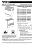
LOCATING THE HEATER -- MINIMUM FRESH AIR OPENING IS 1 SQUARE INCH PER 1,000 BTUIHR.
WARNING: Gas burning appliances require air for combusion and proper venting. Minimum fresh air opening of 1 square
inch per 1000 BTU per hour input rating must be provided for ventilation. EXAMPLE: A 30,000 BTU per hour input unit
requires the equivalent of a 30 inch wide window be open 1 inch for safe operation.
In
1.
2.
3.
4.
5.
A.
choosing the location for the heater, the following factors should be considered:
Convenience to gas supply.
Arrangement of rooms or area to be heated.
Probable location of funiture.
General appearance.
Safe clearance from anything that could catch fire.
B.
Locate the heater centrally in the area which it is to heat. The ideal location is at the source of cold air, which is
an outside wall. If the heater is on an outside wall, the cold air will be warmed before it moves through the room.
C.
Place the heater where the air will circulate freely throughout the area to be heated. If one heater is intended to
heat the entire house, it is adviseable to consider the installation of grilles immediately below the ceilings to permit
circulation of hot air from room to room. Return air grilles are also desirable.
D,
Be certain the heater is placed where the air is free to cimulate around it. Never install the heater in a wall recess.
The minimum clearance required to any wall or object can be found on the rating plate located inside the furnace
control door on the base plate. We recommend a 24-inch min. clearance from the burner access door for the ease
of lighting and for observation of pilot and burner flames.
E.
NOTE: Heater must be installed so that drafthood is in the same pressure zone as the combustion air.
F.
The heater may be placed directly on wood floors.
Heavy pile or shag rugs may restrict normal air flow.
Some floor coverings discolor easily from even low
heat. To assure safe operation, a floorboard extending
the full depth and width of the appliance must be
placed under the heater.
G.
Do not place heater where curtains, draperies, or any
other material may come into contact with any part
of the heater.
REQUIRED
MODEL
200
350
!500
650
SERIES
SERIES
SERIES
SERIES
GAS CONTROLS
A.
All models are equipped with a 100% pilot safety shutoff and a vent safety shut-off system.
C. CAUTION: Do not connect 115V electrical service
"A"
SIDE
2"
6"
6"
6"
MIN.
MIN.
MIN.
MIN.
"B"
CEIUNG
22"
57"
57"
57"
GAS SUPPLY
For L.R gas, the minimum inlet gas supply pressure for
the purpose of input adjustment is 11" water column. The
maximum inlet gas supply pressure is 13" water column.
o"
\
FRONT
VIEW
Gas pressures and input to the burners must not exceed
the rated input and pressure shown on the rating plate.
On Natural Gas the manifold pressure should be 4 inches
water column. The manifoldpressure ,shouldbe 10.5 inches
water column for L.P. Gas.
Orifice change may be required to suit gas supplied.
Check with your WILLIAMS service department.
FOr heater located at elevations between sea level and
2000 feet, the measured input must not be greater than
the input shown on the rating plate of the heater. For elevations above 2000 feet, the measured input must not exceed the input of the rating place reduced by 4 percent
for each 1000 feet that the heater is above sea level.
--5--
3" MIN.
6" MIN.
6" MIN.
6" MIN.
OBSL='RVA'nON
OF PILOTAND BURNER FLAMES.
line to gas control valve or wall thermostat.
For Natural gas, the minimum inlet gas supply pressure
for the purpose of input adjustment is 5" water column.
The maximum inlet gas supply pressure is 7" water
column.
MIN.
MIN.
MIN.
MIN.
"C"
REAR
=
All models are regulated on Natural and L.R gases.
The regulator is built into the gas control valve.
B.
CLEARANCE
Fig. 1
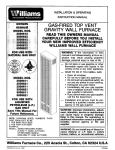
PIPING THE GAS TO THE HEATER
State and local authorities have established codes regulating the installation of gas burning equipment. Consult your
gas supplier or gas company for complete information. In the absence of local codes, all aspects of the installation must
comply with the national fuel gas coda ANSI Z223.1. In Canada: Follow CAN/CGA-B149.1(2) Canadian Standard.
A. Use 1/2-inch pipe or semi-rigid tubing for natural and liquefied petroleum gases. DO NOT USE FLEXIBLE HOSE.
Appliance connectors of corrugated metal tubing and fittings that are listed by a nationally recognized testing agency may be used if accepted by the local code authorities. FOLLOW THE MANUFACTURERS INSTALLATION
INSTRUCTIONS. This type of connector may only be installed in the room where the heater is located.
B. A manual shut-off valve and union must be installed in the gas supply line just ahead of the connection to the heater.
The manual valve must include a lie-inch NPT plugged tapping accessable for connection of a test gauge.
C. Unions in the gas supply lines shall be of the ground joint type. Compounds used on threaded pipe joints must be
resistant to the action of liquefied petroleum gases.
WARNING:
WHEN CONNECTING FIELD PIPING, USE A SECOND WRENCH TO KEEP THE HEATER VALVE FROM TURNING.
SUPPORT FIELD PIPING PROPERLY, STRESS AND OVERTIGHTENING COULD DAMAGE THE GAS VALVE AND
RESULT IN DANGEROUS GAS LEAKS WHICH CAN CAUSE DANGEROUS CONDITIONS INCLUDING PROPERTY DAMAGE, BODILY INJURY, AND EVEN DEATH.
D. A dripleg Fig. 2 should be installed to constitute a trap to catch any condensate that may be in the gas. The dripleg
should be readily accessible for cleaning.
E. The heater must be disconnected from the gas supply system and from the heater individual shut-off valve when
the system is tested at a pressure in excess of 1/2 PSIG.
F. IMPORTANT."CHECK ALL FACTORY AND FIELD PIPE JOINTS FOR GAS LEAKS BEFORE AND AFTER LIGHTING
THE HEATER. USE A SOAP SOLUTION. NEVER USE A MATCH OR OPEN FLAME. CORRECT ANY LEAK, NO
MA'I-rER HOW SMALL.
G. IMPORTANT_ PIPING SUPPLY SHALL BE SUPPORTED TO PREVENT SAGGING DAMAGE TO CONTROLS AND
HAZARDOUS GAS LEAKS. TO PREVENT FREEZING WHERE THE SUPPLY PIPE IS EXPOSED TO COLD AIR,
WRAP THE PIPE OR RUN IT UNDERGROUND.
IMPORTANT
All piping must comply with local codes and ordinances
or with the National Fuel Gas Code (ANSI Z223.1 NFPA
No. 54), whichever applies. (In Canada: CAN/CGA B149.)
DROP
I
1
PIPED
I
I
GAS
(;_OUN0
JOINT
u.loN
PROPER
IMP(RF[CT
_
PIPING
CONTRO
L
PR_rlC_
USI_
MOO(RAT(
AMOUNT
DOPE
PIPED
_UAL
176 _ mini
_
_INI_UM__IRI_PuG_J,n
SHUt 0f_
SUPPLY
NIPPLE
THR£AD
GAS
P_P_
R_T
L_N_T_
L_V_
_ _O
TH_£AD$
tEE
TOP
•
Nippt
'
I
I
I
],_
I;6
Z n._,l
E
s
'i(,°2
LEFT
SIDE
_<. cAP
MINlP,¢UM
,_ALt
/_
OF
81[NO_
CAUIION
rO
P_EVI_N_
4_
Ml_Zat,i
SMUT
Ga_
OC,
C IUHlld
rt_.
fROM
MA_
_ _LL_tlC
G S.OULD
._._
! .[
_UOI_.=V
WORK
0[
SMOOIH
BCFOR_
Ag_A
N(MOVII_G
_T
FON
(NO
GAS
CAP
L_AK
350 MODEL SERIES SHOWN
Fig. 2
Rg. 3
---6--
_R_
_
WARNING
.WARNING
DANGER OF ILLNESS
BODILY INJURY OR DEATH
THE FURNACE AND ANY OTHER FUEL BURNING
APPLIANCE MUST BE PROVIDED WITH ENOUGH
FRESH AIR FOR PROPER COMBUSTION AND
VENTILATION OF FLUE GASES. MOST HOMES
WILL REQUIRE THAT OUTSIDE AIR BE SUPPLIED
INTO THE FURNACE AREA.
DANGER OF PROPERTY DAMAGE,
BODILY INJURY OR DEATH
EVEN WHEN HOUSE MEETS REQUIREMENTS
FOR UNCONVINED SPACE WITH ADEQUATE AIR
INFILTRATION IT IS RECOMMENDED
THAT A
FRESH AIR INTAKE BE INSTALLED TO LESSEN
THE POSSIBLE DANGERS FROM ANY FUTURE
CHANGES ON THE HOME.
VENTING
WARNING: This heater is equipped with a vent safety shut-off system to protect against improper venting of its combustion products. Tampering with or removal of this control will void the limited warranty and can result in carbon monoxide
(CO) poisoning and possible death.
A.
An effective flue is necessary to carry off water vapor, carbon monoxide (CO), carbon dioxide (CO2), and other
products of combustion. For proper venting, follow the following basic rules for gravity venting, which are:
1.
2.
3.
4.
S.
C.
Keep the flue gases hot.
Follow the vent manufacturer's installation instructions.
Select the proper vent size.
Provide constant fresh air replacement.
For new installation, it is recommended that a Type "B" vent in accordance with its listing be used. A Type "B"
vent is one made of non-combustible, corrosion resistant material of sufficient thickness and cross sectional area
and heat insulating quality to avoid excess temperature on adjacent combustible material and certified by a nationally recognized testing agency. Existing brick flues should be lined to provide an effective vent. Brick chimneys,
even in good repair, may be too large and will not provide sufficient draft to effectively vent a heater.
Use vent pipe of the same size as the outlet on back of heater. In no case should a smaller vent be used.
D.
Avoid a horizontal run of vent pipe whenever possible. When a horizontal run is necessary, the pipe must pitch
upward at least 1/4"to the foot, and must be supported securely and joints fastened by sheet metal screws or rivets.
Under no circumstances should the vent run downhill.
E.
Never put a damper or barometric draft control in a gas vent pipe.
F.
Never end a vent in an open attic or run vent through a wall to the outside without extending it upward above the roof.
G.
Always terminate vent with an approved cowl.
H.
WARNING: ALWAYS SECURE VENT PIPE TO OUTLET ON BACK OF HEATER WITH A SHEET METAL SCREW.
IMPORTANT:
Inspect venting system prior to each heating season.
WARNING
DANGER OF ILLNESS,
BODILY INJURY OR DEATH
DRAFTHOOD SPILLAGE WITH UNOBSTRUCTED
VENTS, INDICATES THAT ADDITIONAL AIR MUST
BE BROUGHT INTO THE STRUCTURE FROM THE
OUTSIDE. KEEP A WINDOW OPEN (MINIMUM 2
INCHES) NEAR THE APPLIANCE UNTIL A PERMANENT AIR DUCT IS INSTALLED.
I
IN
ANY AREA
WHERE
IS DAMAGE,
IN USE. BODILY INJURY OR LOSS OF LIFE. DO NOT INSTALL FURNACE
WARNING:
DANGER
OF OXYGEN
PROPERTY
--7--
Thermostat
Installation
MOUNTING
Models with the last two digits "11" (or) "12" utilize a builtin thermostat control system operated by a heat sensing
bulb located in the burner compartment.
1. To remove thermostat cover, squeeze both sides and
lift.
IMPORTANT
I
2. Connect thermostat wires to the thermal screws on the
back of thermostat base.
ting
tubing.
andle
the bulb with care. Do not kink the connec,
Models with the last two digits "21" (or) "22" are operated
by a millivolt type thermostat. Current to the thermostat
is supplied by the pilot generator. Anticipation settings are
not required.
4.
1. If an old thermostat is being replaced and is in a
satisfactory location and the wiring appears to be in
good condition, use existing wiring. If in doubt, use new
wire.
Push any excess wire back through hole in wall and
plug hole with insulation to prevent drafts from affecting thermostat operation.
Be sure to level thermostat for best appearance, fasten
thermostat base to wall through mounting holes with
screws provided.
5. Replace the thermostat cover.
CAUTION
Do not run wire in any location where it might be
damaged. Avoid slicing thermostat wire unless the
spliced wires are properly cleaned, soldered and
taped.
2. If a new location is chosen or if this is a new installation, thermostat cable must first be run to the location
selected. All wiring must agree with local codes and
ordinances. These instructions cover bringing the wire
down from the attic but it can be run from a basement
or crawl space using similar methods.
NOTE
3. Before drilling hole in wall at selected location, drive
a small finishing nail through the ceiling in the corner
of the wall and ceiling above the thermostat location.
Pull the nail out and push a small stiff wire through the
hole so it can be found in the attic. Drill a 1/2-inch hole
through the ceiling wall plate.
Use #18 Ga. wire as supplied for maximum length of 20
feet. If longer length is needed, use #16 Ga. for maximum
length of 25 feet.
Refer to installation instructions packed in the thermostat
carton if you have any doubt about the above procedures.
Connect thermostat wire, previously run to burner compartment from thermostat, to control valve as shown in
Fig. 4.
4. Probe for obstructions in the partition. Then drill a
1/2-inch hole through wall at selected location for
thermostat.
CAUTION
5. From the attic, feed the thermostat cable or a stiff wire
through wall until even with thermostat location.
LABEL ALL WIRES PRIOR TO DISCONNECTION
WHEN SERVICING CONTROLS. WIRING ERRORS
CAN CAUSE IMPROPER AND DANGEROUS OPERATION. VERIFY PROPER OPERATION AFTER
SERVICING.
6. Snag thermostat cable through hole and pull cable
through hole in wall so that 6 inches of cable protrubes.
7. Route cable to heater.
THERMOSTAT
THE THERMOSTAT
GENERATOR
J
€--- WHITE
GENERATOR
THERMOSTAT
LIMIT SWITCH
BLUE
KNOB
GREEN
WILLIAMS
WILLIAMS
LIMIT
SWITCH
P295000A
P295001A
P172100A (OR)
P172200A
Fig. 4
--8--
(OR}
KNOll
Start-Up Procedure
WARNING
CHECK THE GAS INPUT (NATURAL GAS ONLY)
DANGER OF PROPERTY DAMAGE,
BODILY INJURY OR DEATH.
LIQUEFIED PETROLEUM L.P. GAS IS HEAVIER
THAN AIR AND IT WILL SEI-rLE IN ANY LOW
AREA, INCLUDING OPEN DEPRESSIONS AND IT
WILL REMAIN
THERE
UNLESS AREA IS
VENTILATED.
WARNING
NATURAL GAB HEATING VALUE (BTU PER CUBIC
FOOT) CAN VARY SIGNIFICANTLY, THEREFORE,
IT IS THE INSTALLER'S RESPONSIBILITY TO BEE
THAT BTU INPUT TO THE FURNACE IS ADJUSTED
PROPERLY. FAILURE TO DO SO COULD CAUSE
HEAT EXCHANGER FAILURE, ASPHYXIATION, FIRE
OR EXPLOSION, RESULTING IN DAMAGE, BODILY
INJURY OR DEATH. REFER TO THE NATURAL
FUEL GAS CODE (NFPA-54) TO BE SURE THE FURNACE IS BURNING FUEL AT THE PROPER RATE.
NEVER ATTEMPT STARTUP OF UNIT BEFORE
THOROUGHLY VENTILATING AREA.
Check the heater operation as outlined in the following instructions. If any sparking, odors or unusual noises are
encountered, shut off electric power immediately. Recheck
for wiring errors, or obstructions in or near fan motor (if
equipped).
CHECK GASINPUT
Underfiring could cause inadequate heat, excessive condensation or ignition problems. Overfiring could cause
sooting flame impingement or overheating of heat exchanger.
Before starting natural gas input check, obtain heating
value of gas (BTU per cubic foot) at standard conditions
from your local supplier. This factor is used in "Check the
Gas Input" section and procedure.
AND PRESSURES
For heater located at elevations between sea level and
2000 feet, the measured input must not be greater than
the input shown on the rating plate of the furnace. For
elevations above 2000 feet, the measured input must not
exceed the input of the rating plate reduced by 4 percent
for each 1000 feet that the heater is above sea level.
To measure the input using the gas meter, proceed as
follows:
Gas supply pressure and manifold pressure with the
burner operating must also be as specified on the rating
plate.
lype of Gas
Natural
Manifold Pressure, In. W.C.
4
L.R
10.5
Rated input will be obtained on 2500 Btu propane at 10.5
inch manifold pressure and factory-sized orifices. If LP gas
having a different heating value is supplied, orifices must
be changed by a qualified service technician before the
heater is operated.
CHECK THE MANIFOLD GAS PRESSURE
A tapped opening is provided in the gas valve to facilitate
measuring the manifold gas pressure. A "U Tube"
manometer having a scale range from 0 to 12 inches of
water should be used for this measurement. The manifold
pressure must be measured with the burner and pilot
operating. Any major changes in the flow must be made
by changing the size of the bumer orifice. Check with your
WILLIAMS service department for proper orifice sizing.
Step 1: Turn off gas supply to all other appliances except
the furnace.
Step 2: With the heater operating, time the smallest dial
on the meter for one complete revolution. If this
is a 2 cubic foot dial, divide the seconds by 2; if
it is a 1 cubic foot dial, use the time in seconds
as is. (3,600 = Sec. Per Hr.) This gives the
seconds per cubic foot of gas being delivered to
the heater.
Step 3: Assuming natural gas with a heating value of
1000 Btu per cubic foot and 34 seconds per cubic
foot as determined by step (2), then:
Input: 1,000 X 3,600 + 34 = 106000 Btu Per Hour
This measured input must not be greater than the
input indicated on the rating plate of the heater.
Step 4: Relight all other appliances turned off in step 1
above. Be sure all pilot burners are operating.
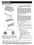
CHECK PILOTBURNER
The pilot flame must envelop 1/2 to 5/8 inch of thermocoupie or generator. See Fig. 5. Pilot flame is preset at the
factory, so ordinarily does not require field adjustment. If
adjustment is needed, see page 14.
J__
CHECK THERMOSTAT
Check thermostat operation. When set above temperature
shown on the thermostat, the main burner should light.
Make certain the thermostat turns off the heater when
room temperature reaches the selected setting and starts
the heater when room temperature falls a few degrees.
1/2 TO5/s
,_--
RLOT
FRONT
_EW
Fig. 5
--9---
FOR YOUR SAFETY,
WILLIAMS
GAS CONTROL
READ BEFORE
LIGHTING
VALVE P322051 (OR) P322052
(OR) P500419 (OR) P5004_,0
I
r WARNING:
If youcausing
do not property
follow these
instructions
a fire
may result
damage,
personal exactly,
injury or
lossorofexplosion
life,
A.
This appliance
has a pilot which must be lighted by
hand. When lighting the pilot, follow these instructions
exactly.
•
B.
BEFORE LIGHTING
smell around the appliance ares
for gas. Be sure to smell next to the floor because some
gas Is heavier than air and will settle on the floor.
WHAT TO DO IF YOU SMELL GAS
• Do not try to light any appliance.
• DO not touch any electric switch; do not use any
phone In your building.
• Immediately
cell your gas supplier
from s neighbor's
phone. Follow the gas suppller's
instructions.
OPERATING
1.
2.
3.
4.
5.
NOTE:
unless
6.
7.
8.
Knob
knob
\l
_
@1/
F_',_%'_/_
call the fire
C,
Use only your hand to push in or turn the gas control
knob. Never use tools. If the knob will not push in or
tom by hand, don't try to repair it, call € qualified service technician.
Force or attempted
repair may result In a
flro or explosion.
D.
Do not use this appliance If any part has been under
water, immediately
call s qualified service technician to
inspect
the appliance and to replace any part of the
control
system and any gas control which has been
under water.
9.
10.
GAS CONTROL
KNOB SHOWN
IN OFF
cannot be turned from "PILOT"
to "OFF"
Is pushed in slightly. Do not force.
Welt five (5) minutes to clear out any gas, then smell for
gas, including near the floor, if you then smell gas, stopl
Follow "B" in the safety Information above. If you don't
smell gas, go to next step.
Loosen wlngnut end open the pilot observation door (if
equipped).
Find pilot--follow metal tube from gas control. The pilot is
mounted on side of burner.
TO TURN
reach your gas supplier,
INSTRUCTIONS
STOP! Read the sefety information
above.
TOm off all electric power to the appliance (if applicable).
Open control access panel.
Tom temperature
dial clockwise F_
to "LO'"
Push in gas control knob slightly and turn
olookwlee !-_
to "OFF."
TEMPERATURE
DIAL
"'_@._:/_--"_@1
"_'F/_
If you cannot
department.
I
11.
12.
13.
14.
Push In gas control
knob slightly and turn
II
counterclockwise
to "PILOT."
Push in control knob all the
way end hold In. Immediately
light the pilot.
THERMOCOUPLE
_
PILOT
BURNER
Continue to hold the control knob In for about one (1)
minute after the pilot is lit. Release knob end It will
pop back up. Pilot should remain lit. If It goes out,
repeat sfop$ 5 through 10.
• If knob does not pop up when released, stop and
Immediately
ceil your service technician or gas
supplier.
• If the pilot will not stay lit after several tries, turn
the gas control knob to "OFF"
and call your service
technician
or gas supplier.
Close pilot observation door, tighten wingnut
(if equipped).
Torn gas control
knob counterclockwise
_'_
to "ON':
Sensing bulb is now activated. Set temperature
dial to
desired temperature
(1 - 5).
Close control access panel.
Torn on all electric power to the appliance
(if applicable).
OFF GAS TO APPLIANCE
1. Turn off all electric power to the appliance If servIce is to be performed (if applicable).
2. Open control access panel.
3.
Push In gas control knob slightly and tum
clockwise F-_ to "OFR" Do not force.
4.
Close control access panel.
WARNING:
DUE TO HIGH SURFACE TEMPERATURES -- KEEP CHILDREN, CLOTHING,
FURNITURE OR ANY COMBUSTIBLE MATERIAL AWAY FROM FURNACE.
IMPORTANT: KEEP BURNER AND CONTROL COMPARTMENT CLEAN.
CONNECTION
SHUT OFF 0E-_IC_
BLACK
BLACK
WIRING
-
DIAGRAM
FOR
BUILT-IN
THERMOSTAT
MODELS
LZGE_O
-FACTORY WIRED LOW VOLTAGE
NOTES:
GAS
VALVE
RE]_OTE BULB
--10--
F k_Y 0F 1_ 01_lU_. NR[ _
€[ m'LAC_ US[O_y t_. 4,_,
IK_JI,,A'nG_
1G6".C.AW
vm[ oR I_/JIVAL_T.FORRDD.
_
Cml_llo_ us[ NO,18 A_O
m _lZO mt ATZZ_TI_ (:ml-)
I
m ..u,tc.us,.,
or,o.o,,i.
A.
This appliance
has a pilot which must be lighted by
hand. When lighting the pilot, follow these instructions
exactly.
B.
BEFORE LIGHTING
smell around the appliance area
for gas. Be sure to smell next to the floor because some
gas Is heavier than sir and will settle on the floor.
•
WHAT TO DO IF YOU SMELL GAS
• Do not try to light any appllancs.
• Do not touch any eieotdc swifch; do not use any
phone In your building.
• Immediately
cell your gas supplier from s neighbor's
phons. Follow the gas suppiier's
Instructions.
OPERATING
1.
2.
3.
4.
If you cannot
department.
reach your gas supplier,
call the fire
C.
Use only your hand to push In or turn the gas control
knob. Never use tools. If the knob will not push in or
tum by hand, don't try to repair it, ceil n qusiified servIce tochnlcien.
Force or attempted
repair may result In a
fire or explosion.
D°
Do not use this appliance if any part has been under
water. Immediately
cell n qusliflnd asrvlce tochniclcn
to
Inspect the appliance and to replace any part of the
control systom and any gas control which has been
under mr.
INSTRUCTIONS
8.
STOP! Resd.the safety Information
above.
Turn off all electric power to the appliance (if applicable).
Open control
access panel.
Push In gas control knob slightly and turn
clockwlse/-"_
to "OFF."
TEMPERATURE
DIAL
"Ibm knob on gas control
counterclockwlas
to "PILOT."
Push In control
knob all the
way and hold in. Immediately
light the pilot.
9.
N
THERMOCOUPLE
5.
6.
7.
Knob cannot
unless
knob 18 pushed
be turned
from "PILOT"
in slightly.
PILOT
BURNER
Continue to hold the control knob in for about one (1)
minute sitter the pilot Is lit. Release knob and it will pop
back up. Pilot should remain lit. If it goes out, repast steps
5 through 9.
• If knob does not pep up when released,
stop and
Immedlntoly
cell your service technician
or gas
supplier.
• If the pilot will not stay lit after several tries, turn
the gas control knob to "OFF"
and cell your service
technfolnn or gas supplier.
KNOB SHOWN
IN "OFF"
POSITION
NOTE:
I
to "OFF"
Do not force.
Wait five (5) minutes to clear out any gas, then smell for
gas, Including near the floor. If you then smell gas, sfopi
Follow "B" In the safety Informstlon
above. If you don't
smell gas, go to the next step.
Loosen wlngnot and open the pilot observation
door (It
equipped).
Find pilot--follow
metal tube from gas control.
The pilot is
mounted
on side of bumer.
10.
11.
Close pgot olmervation door, tighton wlngn_ (if equipped).
Turn gas control knob counterclnckwlasl(
_to "ON".
Burner Is now under control
of the thermostatic
canning
element.
Tum temperature
dial (numbered
1 through 8)
counterclockwise
I_
toward
8 to obtain
desired
temperature.
12.
13.
Close control socese panel.
"rum on MI electric power to the appliance
(If ppgWlcehlo).
TO TURN
OFF GAS TO APPLIANCE
1. Tum off ell electric power to the appliance If servIce Is to be performed (if applicable).
2. Open control access panel.
3.
Push In gas control knob slightly end turn
clockwise _
to "OFF." Do not force.
Close control access panel.
4.
WARNING:
DUE TO HIGH SURFACE TEMPERATURES -- KEEP CHILDREN, CLOTHING,
FURNITURE OR ANY COMBUSTIBLE MATERIAL AWAY FROM FURNACE.
IMPORTANT: KEEP BURNER AND CONTROL COMPARTMENT CLEAN.
CONNECTION
VENT
-%_UT
_
OFF
WIRING
DIAGRAM
FOR
BUILT-IN
I--I]]'ERMOCOUPLE
OE'VIC_
U
BLACK
.[_
GAS VALVE
R_OTE
_11_
I
BULB
THERMOSTAT
MODELS
-FACTORY_RED LOWVOLTAG_
NO'W.S:W AHYOF 15EO_NAL _
AS
_PP_9 _ IH£N=RJ/_¢[
INSl
"
Ik_l.A'lION, 1_" @.AWM¢¢PP£R
_
CG_I4_'I]G_SIJE NO,10 A14_
FOR YOUR SAFETY,
WILLIAMS
READ BEFORE
GAS CONTROL
LIGHTING
VALVE P172100A & P172200A
WARNING:
If youcausing
do not property
follow these
instructions
a fire
may result
damage,
personal exactly,
injury or
lossorofexplosion
life.
A.
This appliance has a pilot which must be lighted by
hand. When lighting the pilot, follow these Instructions
exactly.
B.
BEFORE LIGHTING
smell around the appliance area
for gas. Be sure to smell next to the floor because some
gas Is heavier than air and will settle on the floor.
• It you cannot
department.
WHAT TO DO IF YOU SMELL GAS
• Do not try to light any appliance.
• Do not touch any electric owltch; do not use any
phone In your building.
• Immediately
call your gas supplier from a neighbor's
phone. Follow the gas suppller's
Instructions.
OPERATING
1.
2.
3.
4.
5.
STOPI Read the safety information
above.
Turn off ell electric power to the appliance
Set the thermostat
to lowest setting.
Open control access panel.
Push In gas control knob slightly and tum
clockwlseF-_,
to "OFF."
j
reach
your gas supplier,
call the fire
C.
Use only your hand to push In or turn the gas control
knob. Never use tools. If the knob will not push In or
turn by hand, don't try to repair It, call e qualified servIce technician.
Force or attempted
repair may result In a
fire or explosion.
B,
Do not use this appliance If any part has been under
water. Immediately
call a qualified service technician to
Inspect the appliance and to replace any part of the
control system and any gas control which has been
under water.
INSTRUCTIONS
9.
(If applicable).
10.
GAS CONTROL
KNOB SHOWN
IN "OFF" POSITION
Push In gas control
knob slightly and turn
counterclockwise
_'_
to "PILOT"
GENERATOR
_
PILOT
Push In control knob ell the way and
BURNER
hold in. Immediately
light the pilot.
Continue to hold the control knob In for about one (1)
minute after the pilot Is lit. Release knob and it will
pop back up. Pilot should remain lit. If It goes out,
repeat steps 5 through 10.
• If knob does not pop up when released,
Immediately
call your service technician
supplier.
•
NOTE:
unless
6.
7.
8.
Knob
knob
cannot be turned from "PILOT"
to "OFF"
Is pushed in slightly. Do not force.
TO TURN
1.
2.
3.
4.
5.
11.
Walt five (5) minutes to clear out any gas, then smell for
gas, Including near the floor. If you then smell gas, STOPI
Follow "B'" In the safety Informstlon above. If you don't
smell gas, go to the next step.
Loosen wlngnut and open the pilot observation door (if
equipped).
Find pilot--follow metal tube from gas control. The pilot Is
mounted on side of bumer.
If the pilot will not stay lit after several tries, turn
the gas control knob to "OFF"
and call your service
technician
or gas supplier.
12.
Close pilot observation
door, tighten wlngnut
(if equipped).
Tumgsecontrolknobcountercloukwlse,rF"_to"ON
13.
Close control
14.
"rum on ell electric
(if applicable).
15.
Set thermostat
access
panel.
power
to desired
to the appliance
setting.
OFF GAS TO APPLIANCE
Set the thermostat to lowest setting.
Turn off all electric power to the appliance if service Is to be performed.
Open control access panel.
From "ON" position, depress and turn gas control knob clockwise F_ to "OFF"
Close control access panel.
position. Do not force.
WARNING:
DUE TO HIGH SURFACE TEMPERATURES -- KEEP CHILDREN, CLOTHING,
FURNITURE OR ANY COMBUSTIBLE MATERIAL AWAY FROM FURNACE.
IMPORTANT: KEEP BURNER AND CONTROL COMPARTMENT CLEAN.
CONNECTION
stop and
or gas
W1RING DIAGRAM
FOR WALL THERkiOSTAT
MODELS
LEGEND
-FACTORY WIRED LOW VOLTAGE
(_
SCR'L"W TERMINAL LOW VOLTAGE
NOTE: IF ANY OF 1HE ORIGINAL
_
AS
SUPPt,RD
t_IIf l},lEAR=UA,'MCE
_
E _
_qul_0_.
u_ ONlYt_ 4/04
106"_ AWM00PP_
W_ 0R I_LWN._T.
FOR RB.D _RSl) CONN_I014S USE NO. 111A_
ames_1_ _ ATt.F.AST
tOS'C
{_n_
--12--
''.
WARNING:
If you do not follow these
instructions
exactly,
a fire or explosion
I
I
may result causing property damage, personal injury or loss of life.
A.
This appliance
has a pilot which must be Ughted by
hand. When lighting the pilot, follow these Instructions
exactly.
B.
BEFORE LIGHTING
smell around the appliance area
for gas. Be sure to smell next to the floor because some
gas Is heavier than air end will settle on the floor.
• If you cannot
department.
WHAT TO DO IF YOU SMELL GAS
• Do not try to light any appliance.
• Do not touch any electric switch; do not use any
phone In your building.
• Immedlatsiy
rail your gas supplier from a neighbor's
phone. Follow the gas soppller'a
Inxtroctlona.
OPERATING
1.
2.
3.
4.
5.
STOPI Read the safety Information
above.
Bet the thermostat
to lowest setting.
Turn off all siectrlc
power to the appliance.
Remove control access panel.
Push In gas control knob slightly and turn
clockwise F_
to "OFF."
t/
NOTE:
unless
6.
7.
8.
__ \_1
your gas supplier,
call the fire
C.
Use only your hand to push In or turn the gas control
knob. Never use tools. If the knob will not push In or
turn by hand, don't try to repair It, call a qualified aervIce technician.
Force or attempted repair may result In a
fire or explosion.
B.
Do not use this appliance
If any part has been under
water. Immediately
call a qualified service technician to
Inspect the appliance
end to replace any part of the
control system end any gas control which has been
under water.
INSTRUCTIONS
9. Turn knob on gas control
counterclockwise
to "PILOT."
(If applicable).
GENERATOR
PILOT
BURNER
.s CONTROL
t "-'_;_
10. Push In control knob all the way end hold In. Immediately light the pilot.
Continue to hold the control knob In for about one (1)
minute after the pÁÁÙtIs lit. Release knob end It will pop
back up. Pilot should remain lit. If It goes out, repeat
steps 5 through 10.
KNOB SHOWN
'"OFFPOSITION
Knob cannot be turned from "PILOT"
to "OFF"
knob Is pushed in slightly. Do not force.
Walt five (5) minutes to clear out any gas, then smell for
gas, Including near the floor. If you then smell gas, atopl
Follow "B" In the safety Information above. If you don't
smell gas, go to the next step.
Loosen wlngnut and open the pilot observation door (If
equipped),
Find pnot--follow metal tube from gas control. The pilot Is
mounted on side of burner.
TO TURN
1.
2.
3.
4.
5.
reach
•
If knob does not pop up when released,
Immedlataty
call your service technician
supplier.
stop and
or gas
•
If the pilot will not stay lit after several tries, turn
the gas control knob to "OFF"
and call your service
technician
or gas supplier.
11. Close pilot observation
door, tighten wlngnut
(If equipped).
12. Turn gas control knob counterclockwise
_'_
13. Close
control
access
14. Turn on all electric
15. Set thermostat
to "ON".
panel.
power to the appliance
to desired
(if applicable).
setting.
OFF GAS TO APPLIANCE
Set the thermostat to lowest setting.
Turn off all electric power to the appliance If service Is to be performed.
Open control access panel.
Push In gas control knob slightly and turn clockwise F_ to "OFF" pesltlon.
Close control access panel.
Do not force.
WARNING:
DUE TO HIGH SURFACE TEMPERATURES m KEEP CHILDREN, CLOTHING,
FURNITURE OR ANY COMBUSTIBLE MATERIAL AWAY FROM FURNACE.
IMPORTANT: KEEP BURNER AND CONTROL COMPARTMENT CLEAN.
CONNECTION
V ENT
SHUT
SAFETTH
OFF
E_.._
DEVICE1
_
WIRING
TAT
-I
DIAGRAM
_-]
I
FOR WALL
THERMOSTAT
LEGENO
GENERATOR
1
I
_1_
GAS
VALVE
/
MODELS
BLACK
--13---
FACTORY
WIRED
LOW
VOLTAGE
SCREW TERMINAL LOW VOLTAGE
IF ANY OF 11tE 0RIGINAL Y&_E AS
_
tlrD.I 11tE ,N,RJ/gI(Z MUST
E RER,AC_),
USEONLY
tlIQ,_,4,4H
INSULA'IIaN,
106"_ Al_l
_R£ ORI_IVN.B_T. F0RRELDtfRB)_
USENO.18AI_
'lq9 w,'rm_ ATtL_r tes,c(_w)..
How To Care For Your Heater
CABINET FINISH
Clean cabinet with damp rag. Never use abrasive cleaners.
Cabinets are finished with heat resistant baked enamel
-- DO NOT refinish with wall paint.
REMOVABLE CABINET TOP (350, 500, & 650 MODEL
SERIES ONLY)
For ease of cleaning, access or replacement of internal
parts, the top of this heater can be removed by following
these steps: Refer to Fig. 6.
1. Remove (3) Brackets on roar of heater securing Cabinet
Top to Back Plate.
2. Pull Cabinet Top forward and lift up. Reinstall Cabinet
Top by reversing the procedures noted above.
NOTE: Take Special care to engage the (6) clips located
on the bottom of the Cabinet Top into the top flange of
heater sides.
CLEANING BURNER COMPARTMENT
Because cold air is attracted to the flame during furnace
operation, a build up of lint from bedding and dust (etc.)
in the burner area will occur each heating season. It is
necessary to clean this area regularly. Use a vacuum
cleaner with a narrow attachment to reach small areas.
Be careful in and around the pilot. A change in its adjustment could be made if struck during cleaning.
HEATER AREA
DANGER
A BUILDUP OF ANY DUST, LINT OR FOREIGN
MATERIAL IN THE PARIMARY AIR OPENING OF
THE BURNER CAN INTERFERE WITH THE PROPER AIR GAS MIXTURE AND CAN RESULT IN A
YELLOW FLAME WHICH CAN PRODUCE CARBON MONOXIDE AND SOOT. THIS CONDITION IF
ALLOWED TO DEVELOP, CAN LEAD TO BODILY
INJURY INCLUDING DEATH. IT IS IMPERATIVE
THAT THE BURNER BE KEPT CLEAN.
Keep the area near the heater clear and free from combustible materials, gasoline, and other flammable liquids
and vapors.
COMBUSTION
AND VENTILATION
REMOVABLE CABINE'r TOP
(350, 500, & 650 MODEL SERIES)
*NOTS:
(3) BRACKETS
AIR
The combustion and ventilation air supply must not be
blocked
CABINET
TOP
--
TO REMOVE CABINET TOP.
REMOVE (3) BR._CKETS
ON REAR OF HEATER.
PULL CABINET
AND LIFT UF_
-_
\
TOP FORWARO
Do not put anything in or on the heater cabinet.
For better circulation and more effective heating, do not
place obstructive furniture closer than four feet to the front
of the cabinet or two feet to the side of the cabinet.
ANNUAL UPKEEP NEEDED
TABS
It'is recommended that a qualified service technician per•form these checks st the beginningof each heating season.
CLEANING BLOWER (if equipped)
Shut off electricity. Clean any lint or dirt from fan blades,
fan motor, and exposed air passages. Use a brush.
PILOT BURNER
Light pilot using instructions in OPERATING YOUR FURNACE on pages 10 through 13. Leave thermostat at lowest
setting.
Pilot flame should surround 1/2 to 5/8 inch of the generator
or thermocouple tip. Refer to Fig. 5, page 9. If flame needs
adjusting, do so as follows:
ADJUST
SIDE
Fig. 6
VENT SYSTEM
Make sure that no parts of the venting system are blocked or rusted. Clean or replace before using furnace.
PILOT BURNER Refer to Fig. 7.
1. Remove screw cover over pilot adjusting screw.
2. Insert small screwdriver. Adjust flame as needed. Turn
screw counterclockwise (_"_) to increase flame,
clockwise (r'_) to decrease.
3. "rumthermostat to highest setting. Main burner should
light quickly and smoothly.Turn thermostatto lowest setting. Main burner should go out. Pilotshould remain lit.
4. Replace screw cover with gasket over pilot adjusting
screw.
"i'
•
I
G
SIDE
TOP VIEW
BURNER CLEANING
Check burner. If cleaning is required, contact a qualified
service technician to clean and service burner.
VIEW
Flg. 7
NOTE: A properly adjusted bumer with nearly all gases will produce a flame which has clear blue cone having
a bluleh.red or bluish-violet outer mantle. In the case of PURE BUTANE GAS, a very slightly yellow tip (Y4" maxImum length) Is usually present.
--14---
INSTALLATION
&
2101
(AVAILABLE
ONLY
OPERATING
BLOWER
FOR
INSTRUCTION
ACCESSORY
350,
500, & 650
NOTE:All electrical work must be conform to your local
codes and ordinances or in their absence, with
National Electrical Code,ANSI/NFPA 70. If
you are not famnlar with wtdng codes In general,
havea competentdectrlclando this job. in CANADA
CANADIANELECTRICALCODE C22.1.
MODEL
SERIES)
WARNING
OR DEATH.]URN OFF ElECTRiCAL
POWERSUPPLY
AT
DISCONNECT
S
WITCH,FUSE
BOX
OR SERVICE
DANGEROF PROPERTYDAMAGE,BODILYINJURY
PANEL BEFOREREMOVINGOR WORKINGFAN.
WARNING: This appliance
is equipped with a threeprong (grounding)
plug for
/our protection
against
shock hazard
and should
L
(EXAMPLE
I)
650 SERIES
500 SERIES
EXAMPLE 2)
350 SERIES
be plugged directly into a
)roperly grounded
threeprong receptacle.
DO NOT CUT OR REMOVE
THE PRONG. Oil motor
every
6 months
with a few drops
of SAE 20 motor
oil.
A:
B:
C:
D:
E:
F:
G:
H:
J:
MOTOR & BLOWER
GAS VALVE
CONDUIT
CONTROL ROD
CABLE CLAMP
CORD & PLUG
CONTROL BOX
TEMPERATURE
DIAL
BLOWER SPEED
SELECT SWITCH
K: FAN LIMIT SWITCH
L: SENSOR MOUNTING
BRACKET
M: SPILL SWITCH
B
FIG,1
A.
BLOWER ACCESSORY
.A
N:
KIT INSTALLATION
This accessory
is installed
on heater
back
through
heated
space. A 115V 60Hz outlet
NOTE: WALl THERMOSTAT
MODELS ONLY
and will increase
adjacent
to the
COUPLING
circulation
of warm
furnace
is required,
air
Control Rod (D), Temperature
Dial (H), and Coupling
(N) are not used or supplied
with Wall Thermostat
Models. Wall Thermostat
Models utilize a mlllivolt Thermostat
for Temperature
Control.
For Wall Thermostat
Model installations,
disregard
STEPS
and STEP 4 on these instructions.
INSTALL
AS
STEP
1.
Choose
a location
for heater
5 feet to rear of heater.)
STEP
2. Place motor
& blower (A) on heater
floor, securing with (4)
in RG.1. Also place control box (G) near the top of furnace
(21 screws as shown In RG.1.
FOLLOWS:
(NOTE:
STEP
3
5. Attach
screw
Install
this
klt
by using
installation
the
holes
temperature
dlal (H) to hole free
and set assernby aside for now.
--15--
near
115v
in cabinet
end
electrical
outlet
(within
screws as shown
back, securing with
only.)
of control
rod
(D).
Tighten
set
INSTALLATION
(con't)
& OPERATING
21 01
INSTRUCTION
BLOWER ACCESSORY
STEP
4.
Remove
temperature
dial from
control
valve (B) and discard.
Install the
coupling
(N) to control
valve and secure
it by tightening
set screw.
Slide previously
assembled
control
rod down through
control
box and insert
it into coupling
attached
to the control
valve.
Secure
rod to couplincj
with
cotter
pin.
STEP
5.
Secure
cable
provided.
STEP
6.
(Refer
to
clamp
RG.1
(El
page
to
the
heater,
151 Insert
fan
as
shown
sensor
switch,
in
FIGURE
attached
1,
with
to
fan
screw
limit
switch (K), into sensor mounting
bracket
(L) as shown in FIG.1.
See correct
bracket
location
for your model in example
1 and 2.
IMPORTANT: When inserting
sensor bulb into mounting
bracket
be careful
not to push bulb compleUy
thru mounting
bracket,
stopping before sensor
switch tip is exposed
at other end of bracket.
When installing
sensor switch
into mounting.bracket
be sure sensor bulb is not touching
spill switch
connectors
(M).
B. BLOWER
OPERATION
I. With heater cold (allow to cool if heater has been
into available 115volt wall outlet.
operating), insert plug (F)
2. Turn heater on and allow to operate
10 minutes.
3. Set blower speed select switch (J) to either "LO" or "Hi" position to obtain desired
air movement.
(Blower
accessory
will not operate
if blower speed select switch is
set in "OFF"
position.)
4. For Built-In
type Thermostat
Models, turn Temperature
Dial (H) to desired
tamp
settings.
For Wall type Thermostat
Models turn Wall Thermostat
Dial to
temperature
settings.
5.
To turn
off
blower, set
blower
speed
WIRING
21 01
select
switch
to "OFT"
position.
--
CAUTION
DIAGRAM
BLOWER ACCESSORY
L
115VA¢
I
_
"I
I
LEGEND
(J)
I
HIGH VOLTAGE FIELD
HIGH VOLTAGE FACTORY
'--'
......
0
BK-BLACK
Label all wires prior to disconnection
when servicing
controls.
Wiring
errors con
cause improper
and dangerous operation.
Verify proper
operation
after servicing.
WIRE CONNECTORFOR UNE VOLOTAGE
FACTORY WIRING
BL==BLUE W==WHITE R-RED
G==GREEN
NOTE: IF ANY OF THE ORIGINALWIRE AS SUPPLIED WITH THE
APPLIANCEMUST BE REPLACED,USE ONLY 18GA, 4/64"
INSULATION,105"C. AWM COPPER WIRE OR EQUNALENT.
FOR FIELD WIRED CONNE:Cl]ONSUSE NO. 18 AWG WIRES
RA'I'_D FOR AT LEAST
105"C (991"_
--16--
INSTALLATION
&
2101
-
OPERATING
BLOWER
INSTRUCTION
ACCESSORY
- REPLACEMENT PARTS
(350,
500,
&: 650
MODEL SERIES
ONLY)
13
17
0
2
3
NO._._ ITEMS 5,6,7, & 16 ARE NOT
SUPPUED OR REQUIRED Y,IIH
WAll TYPE THERMOSTAT MODELS
(USE
ITEM
NO.
PART
REPLACEMENT PARTS LIST MANUFACTURES
ONLY
NO.
P500250
ASSEMBLY,
2
K7003-6087
PLATE,
3
P500137
BLOWER
4
K5150-6029
5
SEE P_
_
18
ASSY,
MOTOR
MOTOR
MTG.
WHEEL
BLOWER
CONTROL
PARTS)
ITEM
PART NO.
NO.
11 P500263
DESCRIPTION
1
AUTHORIZED
HOUSING
ROD
FAN
UMIT
SWITCH
12
(000062
BASE,
13
P065800
SCREW,
14
K000061
WRAPAROUND CON'IROL BOX
15
P320911A
SPEED
SEE PAGE 21
CONTROL
#10
BOX
X 1/2
SELECT
SWITCH
6
P500125
COTTER
7
P500026
GROMMET,
8
P500156
CORD &: PLUG
18
9
P500158
BUSHING
19
PARTOF FURNACE SENSOR MOUN1]NG BRACKET
11o
P097500
20
PART OF FUB_ACESCREW,
!SCREW,
PIN
DESCRIPTION
16
WHITE
-
17
STRAIN
_t_B-32
X 3/8
NO'W.: Screws, bolts end woshers ore _endla'd
hll,'dware Rims
--17--
rr_ =4
P50014,5
K000143
TEMPERATURE
SET SCREW,
CABLE
end moy be purchosed
DIAL
BOX CON.
CLAMP
_
X 3/8
locally,
S.M.
WILLIAMS
GAS FIRED
ROOM HEATER
REPLACEMENT
PARTS FOR
20016
MODEL SERIES
I
•
I
.j"
j"
I
i
I
I
I
I
I
J
FOR PARTS UST
SEE PAGE 19
USE ONLY MANUFACTURER'S
AUTHORIZED PARTS
--18---
REPLACEMENT PARTS FOR MODELS
2001611 2001612
2001621 2001622
!KE'_
NO.
DESCRIPTION
2001611
2001612
2001621
2001622
1
WRAPPER ASSEMBLY
K000275
K000275
K000275
K000275
2
DRAFT DIVERTER ASSY.
K000274
K000274
K000274
K000274
KOOO27g
K000279
K000279
K000279
COMBUSTION CHAMBER
3
ASSEMBLY
4
BASE PLATE
K000265
K000265
K000265
K000265
5
VALVE BRACKET
K000266
K000266
K000266
K000266
6
CONTROL VALVE
P322052
P322051
P172200A
P172100A
7
BURNER ASSEMBLY
K000301
K000301
K000301
K000301
8
ORIRCE ADAPTER
P500393
P500393
P500393
P500393
9
BURNER ORIFICE
P090568
P090547
P090568
P090547
10
PILOT NAT.
P500019
PILOT L.P.G.
IOA
P500020
PILOT NAT.
P322274
PILOT LP.G.
P322275
11
THERMOCOUPLE
P322391
P322391
12
ELECTRODE
P322392
P322392
P322276
P322276
13
IGNITER BRACKET
7A189
7A189
7A189
7A189
14.
VENT UMIT CONTROL
P500406
P500406
P500406
P500406
15
THERMOSTAT
P322016
P322016
16
WIRE ASSEMBLY
P500409
P500409
P500409
P500409
17
MANUAL SPARK IGNITOR
P285500
P285500
P285500
P285500
FOR PARTS ILLUSTRATION, SEE PAGE 18
NOTF._ Screws, bolts and washers are standard
hardware Items
--19--
and may be purchased
locally
WILLIAMS
GAS FIRED
REPLACEMENT
350,
FOR PARTS LISTING
SEE PAGE 21 (OR) 22
USE ONLY MANUFACTURERS
AUTHORIZED PARTS
500,
&
(ENCLOSED
650
ROOM HEATER
PARTS
MODEL
SERIES
CONSOLES)
./_-.,._
NOTE:
ITEMS 24 AND 18 ARI_
NOT USED OR SUPPLIED WITH
WALL THERMOSTAT MODELS
__
>
_2o--
ENCLOSED CONSOLES
REPLACEMENT PARTS FOR
BUILT-IN
THERMOSTAT MODELS
3501512
3501912
<EY
_10.
3501511
3501911
DF_..SCRIP'IION
1
PANEL SIDE (R.H.)
2
NOT USED (OR PROVIDED)
5001512
5001912
5001511
5001911
6501512
6501912
6501511
6501911
3501512
3501912
3501511
3501911
5001512
5001912
5001511
5001911
6501512
6501912
6501511
6501911
K000204
K000204-
K000205
KC00205
K000206
K000206
,.3 INLET DUCT
' K7000.-6022
<7000-6022
K7000--6022
K7000-6022
K7000-6022
K7000-6022
#
BoI"rOM LOUVER ASSY.
iK000182-1
K000182-1
K000182-2
K000182-2
K000182-3
K000182-3
5
CENTER PANEL
K000220
K000221
K000221
K000222
K000222
6
BO'I'roM. CABINET
7
PANEL SIDE (LH.)
K000207
K000207
K000208
K000208
K000209
K000209
5
WIRE ASSEMBLY
P50040g
P500409
P500416
P5004.16
P500416
P500416
g
K000220
KSOiX)-6003 K5000--6003
K5000-6OO4. K5000-6004
KSOOO.-601g K5000.-6019
TOP LOUVER ASSEMBLY
K000181
K000181
K000212-1
K000212-1
K000212-2
K000212-2
10
COMBU_'_ION
_
t<000242
K000242
1<000240
K000240
K00004.5
K00004.5
11
STEEL BURNER
P50024.4-
P50024.4
P50024.5
P50024.5
P500246
P500246
12
CABINET COVER ASSY.
K000223
K000223
K000224
K000224
K000225
K000225
13
CONTROL BRACKET
K000147
K000147
K000147
K000147
K000147
K000147
14
BURNER ORIFICE
P500336
P500351
ASSY.
P500330
P500347
P500327
P500343
15
ORIRDE FIT'nNG
P500086
P500056
P500086
P500086
P500086
P500086
16
MANIFOLD PIPE
P500087
P500087
P500088
P500088
P500089
P50008g
17
GAS CONTROL VAL_,/E
P5004.19
P500420
P5004.19
P500420
P500419
P5004.20
18
CONTROL ROD
K000148-1
K000148-1
K000148-2
K000148-2
K000148-2
K000148-2
10
PILOT TUBE
P012000
P012000
PO12000
P012000
PO12000
P012000
KO00080
KO0008O
KO00080
KO00080
KO00080
KO0008O
K7m1-6030
K7011-6030
K7011-6031
K'7011-6031
20 I GAB VALVE HEAT SHIELD
I
21 I SHIELD COVER
22
1HERMOCOUPLE
P321828
P321825
P321828
P321825
P322391
P322391
23
PILOT-
P500019
P500020
P500019
P500020
P500019
P500020
24. TEMPERATURE DIAL
P500126
P500126
P500126
P500126
P500126
P500126
25
VENT UMIT CONTROL
P5004.72
P5004.72
P5004,06
P5004.06
P500118
P500118
26
HEAT SHIELD (REAR)
K7003-83"/0
K7003-6370
K7003-6371
K7003-6371
K'/003-6372
27
BACI( PLA'I_
K000226
28
REAR CORNER BRACE
K7003-6097
"_NOT
BURNER
K000226
K000227
K000227
KT(X)3--6097 1(7003--6097 K7003.-6097
K000228
K7003-6097
K7(X)3-6372
K000226
K7003--60_17
_,'10_1
NOTE: Screws, bolts and washers are standard
hardware Items
FOR PARTS ILLUSTRA110N, SEE PAGE 20
--21--
and may be purchased
locally
ENCLOSED CONSOLES
REPLACEMENT PARTS FOR
WALL THERMOSTAT MODELS
3501522
3501922
KE_
NO.
1
3501521
3501921
DESCRIP'IION
PANEL SIDE (R.H.)
2 ' THERMOSTAT
5001522
5001922
5001521
5001921
6501522
6501922
6501521
6501921
3501522
3501922
3501521
3501921
5001522
5001922
5001521
5001921
6501522
6501922
6501521
6501921
K000204
K000204
K000205
K000205
K000206
K000206
P322016
P322016
P322016
P322016
P322016
P322016
3
INLET DUCT
K"/000-.6022
K7000.-6022
K7000-6022
K7000.-6022 K7000-6022
KT(XX)-6022
4
BOTTOM LOUVER ASSY.
K000182-1
K000182-1
K000182-2
K000182-2
K000182-3
K000182-3
5
CENTER PANEL
K000220
K000220
K000221
K000221
K000222
K000222
6 i Bo'rroM, CABINET
K5000-6003
K5000--6003
K5000-6004
K5000-6004
K5000-601111 K5000--6019
7
PANEL SIDE (LH.)
K000207
K000207
K000208
K000208
K000209
KO0020g
8
_RE
P500409
P500409
P500416
P500416
P500416
P500416
g
TOP LOUVER ASSEMBLY
K000181
K000181
K000212-1
K000212-1
K000212-2
K000212-2
K000240
K000240
K000045
K000045
AS_BLY
10
COMBUSTION
Cl_
ASSY.
K000242
K000242
11
STEEL BURNER
P50024.4.
P500244
P500245
P50024.,5
P50024.6
P500246
12
CABINET COVER ASSY.
K000223
K000223
K000224
K000224
K000225
K000225
13
CONTROL BRACKET
K000147
K000147
K000147
K000147
K000147
K000147
14.
BURNER ORIFICE
P500336
P500351
P500330
P500347
P500327
P500343
15
O_RCE FITI'ING
P500086
P500086
P500086
P500086
PSOOOB6
P500086
16
MANIFOLD PIPE
P500087
P500087
P500088
P500088
P500089
P500089
17
GAS CONTROL VALV1E
P172100A
P172200A
P172100A
P172200A
P172100A
P172200A
18
NOT USED (OR PROVIDED)
19
PILOT TUBE
P012000
PO12000
P012000
P012000
P012000
P012000
KO00080
KO00080
KO00080
20
GAS VALVE HEAT SHIELD
21
SHIELD COVER
22
NOT USED (OR PROVIDED)
23
PILOT -
24
NOT USED (OR PROVIDED)
25
BURNER
KO00080
KO00080
KO00080
K7011-6030
K7011-6030
KTO11-B031 1(7011-8031
P322274
P322275
P322274
P322275
P322274
P322275
VENT UMIT CONTROL
P,500472
P500472
P500406
P500406
P500118
P500118
26
HEAT SI-IIELD (REAR)
,K7003-6370
27
BACK PLATE
K000226
28
RF_ARCORNE_ BRACE
K7003-80_
"_
NOT _
K7003-6370
K000226
K7003-6371
K000227
1(7003-6(307 K7003-eOg7
NOTF_ Screws. bolts and woshers are etandard
K7(X)3-6371
K000227
K7003-60e7
hardware Item=
FOR PARTS ILLUS'I1RA'nON, SEE PAGE 20
--22--
K7003-6372
K000228
K7003-60_
KT(X)3-6372
K000228
K7(X)3-60e7
and may be purchased
locally
Service
Hints
If your heater fails to work right, you may avoid inconvenience
and the cost
of a service call by checking the following points before you call for service.
FOR YOUR SAFETY
owners
manual
MODEL NOS.
FOR NAT. GAS ONLY
2001612;
3501512;
3501912;
5001512;
5001912;
6501512;
6501912;
2001622
3501522
3501922
5001522
5001922
6501522
6501922
Do not store or use gasoline
or other flammable vapors and
liquids in the vicinity of this or any
other appliance.
POSSIBLE CAUSE
If you smell gas:
1. Open windows.
2. Don't touch electrical.
3. Extinguish any open flame.
4. Immediately call your gas
supplier.
WHAT TO DO
If your heater Is not heating or not giving enough heat -Thermostat is not set correctly.
Reset thermostat to desired setting.
Pilot is out.
Check pilot. Relight if necessary
following instructions for "Operating
Your Heater."
Pilot is on but burnerwon't
come on.
If gas valve is set at other than "On"
heater will not operate. Shut heater
down and follow instructions for
relighting in "Operating Your Heater"
section.
Burner is not operating
properly.
Check flame. If it is yellow the burner
is not getting enough air. Or if flame
is blue and noisy and seems to lift off
the burner, the burner is getting too
much air. See page 14.
Check that doors, drapes or furniture
are not blocking heater louvers.
Air flow restricted.
MODEL NOS.
FOR L.RGAS
ONLY
2001611; 2001621
3501511; 3501521
3501911; 3501921
5001511; 5001521
5001911; 5001921
6501511; 6501521
6501911; 6501921
FOR YOUR SAFETY
Pilot goes out time after time -Heater flue blocked.
If bumer is noisy -Gas input amount is incorrect.
Too much primary air.
If blower does not run -(if equipped)
Fan switch not set.
Blower not connected to
electric power.
If blower motor is noisy -(if equipped)
Housing rattling.
Blower dirty.
Blower wheel bent.
Locate vent outletblockage and
clean.
Contact Williams Service Department.
Contact Williams Service Department.
Select fan speed.
Connect to electricpower.
Tighten screws.
Clean blower wheel.
Straighten or replace.
See troubleshooting section for more detailed information.
How to Order Repair Parts
When ordering
information:
1.
2.
3,
4.
repair parts, always give the following
MODEL NUMBER
MFG. DATE CODE
PART NUMBER
PART DESCRIPTION
All parts listed herein may be ordered from your equipment supplier.
The Model Number of your Williams room heater will be
found on the rating plate near gas valve, inside control
compartment.
WILLIAMS FURNACE COMPANY
225 Acacia Street
Colton, CA 92324 USA
(909) 825-0993
© 1998 The Williams Furnace Company
Pdnted in U.S.A.
MANUFACTURED
IN THE U.S.A.
Established 1916
FAX: (909) 824-8009
Rev. 4/98
P500407