1
INSTALLATION & OPERATING
INSTRUCTION MANUAL
owners
manual
MODEL NOS.
2509612
2509622
GAS-FIRED TOP VENT
GRAVITY WALL FURNACE
READ THIS OWNERS MANUAL
CAREFULLY BEFORE YOU INSTALL
YOUR NEW IMPROVED EFFICIENCY
WILLIAMS WALL FURNACE
WARNING:
If the information in this|
manual is not followed exactly, a fire or explosion
may result causing property
damage, personal injury or loss of life.
--
-!ii_I
MODEL NO_:!i_
2509611
2509621
3509611
3509621
5009611
5009621
FOR USE WITH
LIQUEFIED
PETROLEUM
(L.P.)
GAS ONLY
Save This Manual For
Future Reference.
NOTE: CANADIAN MODEL NUMBERS THIRD
DIGIT FROM LEFT TO BE:
1 FOR BASIC ALTITUDES
2 FOR HIGH ALTITUDES
EXAMPLE:
MODEL: 3509612 BECOMES 3519612
(0-2000 FT, BASIC ALTITUDE)
OR BECOMES 3529612
(2000-4000 FT. HIGH ALTITUDE)
Williams
PRINTED
IN US,A.
1
Do not store or use gasoline or other
flammable vapors and liquids in the
vicinity of this or any other appliance.
WHAT TO DO IF YOU SMELL GAS
• Open all windows.
• Do not try to light any appliance.
• Do not touch any electrical switch; do
not use any phone in your building.
• Extinguish any open flame.
• Immediately call your gas supplier
from a neighbor's phone. Follow the
gas supplier's instruction.
• If you cannot reach your gas supplier,
call the fire department.
Installation and service must be performed by a qualified installer, service
agency or the gas supplier.
WARNING: Improper installation,
adjustment, alteration, service or maintenance
can cause injury or property damage.
Refer to this manual. For assistance or
additional information consult a qualified
installer,
service
agency
or the gas
supplier.
WARNING: Do not install any of these furnaces (Natural or L.R Gas) in mobile
homes, trailers, or recreational vehicles.
Furnace Co., 225 Acacia St., Colton, CA 92324 U.S.A
5/97
P322085
Contents
Williams Installation Policy ......................
Introduction ..................................
Basic Description ..............................
Helpful Installation Information ...................
Safety Rules .................................
Unpack Your Furnace ..........................
Basic Tools Needed ............................
Basic Materials ...............................
Optional Accessories ...........................
Installing Your Wall Furnace .....................
Locating Wall Furnace and Thermostat ............
Combustion & Ventilation Air ...................
Recessed Mount Installation ..................
2
3
3
3
4
5
5
5
5
6
6
7-9
10-11
Surface Mount Installation ......................
Vent Installation ..............................
Mount The Furnace ...........................
Gas Supply and Piping ......................
Thermostat Installation ......................
Start Up Procedure .........................
Operating Your Furnace .....................
How To Care For Your Furnace ...............
Furnace Technical Information ..................
TROUBLESHOOTING CHART ................
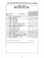
Replacement Parts .........................
Blower Accessory (2901) ....................
SERVICE HINTS ......................
How To Order Repair Parts .............
12
12
13
14-15
15-16
17-18
18-23
24-25
25
26-27
28-35
36-37
Back Cover
Back Cover
Your Warranty
The Manufacturer,
LIMITED
Williams
ONE-YEAR
Furnace Co.. warrants this wall furnace or heater to the original purchaser under the following
1. Any part thereof which proves to be defective
Manufacturer's option, FOB its factory.
in material or workmanship within one year from date of original purchase for use will be repaired or replaced at the
2. No liability is assumed by the Manufacturer for removal or installation labor costs, nor for freight or delivery
LIMITED
conditions:
WARRANTY
EXTENDED
charges,
WARRANTY
1. In addition to the above limited one-year warranty on the complete unit, any heat exchanger which burns out or rusts under normal installation, use and service
conditions during a period of nine years following expiration of the one-year warranty period will be exchanged for a like of functionaJly similar part, FOB Manufacturer's factory.
2. No liability
is assumed by the Manufacturer for removal or installation labor costs, nor for freight
or delivery
charges.
LIMITATIONS
1. THIS LIMITED WARRANTY IS THE ONLY WARRANTY MADE BY THE MANUFACTURER.
IMPLIED WARRANTIES OF MERCHANTABILITY OR FITNESS FOR
ANY PARTICULAR PURPOSE ARE LIMITED TO THE SAME ONE YEAR TERM AS THIS EXPRESS WARRANTY. UNDER NO CIRCUMSTANCES
SHALL THE
MANUFACTURER
BE LIABLE FOR INCIDENTAL, CONSEQUENTIAL,
SPECIAL OR CONTINGENT DAMAGES OR EXPENSES ARISING DIRECTLY OR INDIRECTLY FROM ANY DEFECT IN THE PRODUCT OR ANY COMPONENT
OR FROM THE USE THEREOF THE REMEDIES SET FORTH HEREIN ARE THE EXCLUSIVE
REMEDIES AVAILABLE TO THE USER AND ARE IN LIEU OF ALL OTHER REMEDIES.
Some states do not allow limitations on how long an implied warranty lasts, and some states do not allow the exclusion or limitation
or consequential damages, so the above limitations or exclusions may not apply to you.
of incidental
2. This warranty does not include any charge for labor or installation.
3. This warranty does not extend to painted surfaces nor to damage or defects resulting from accident, alteration, misuse or abuse, or improper installation.
4. This warranty does not cover claims which do not involve defective workmanship or materials.
DUTIES OF THE CONSUMER
1. The heating equipment must be installed by a qualified installer and operated
equipment
2. Any travel, diagnostic
in accordance with the installation and homeowner's
costs, service labor, and labor to repair the defective unit will be the responsibility
instructions furnished with the
of the owner.
3. A bill of sale, cancelled check, payment record or permit should be kept to verify purchase date to establish the warranty period
4. Have the instafler enter the requested information in the space below.
GENERAL
1. The Manufacturer neither assumes nor authorizes any person to assume for it any other obligation or liability in connection
with said equipment.
2. Service under this warranty should be obtained by contacting your dealer. Provide the dealer with the model number, serial number and purchase date verification.
3. If. within a reasonable time after contacting your dealer, satisfactory
CA 92324, for assistance,
4. THIS WARRANTY
INSTALLATION
Model
Orig.
GIVES YOU SPECIFIC
service has not been received,
LEGAL RIGHTS. AND YOU MAY ALSO HAVE OTHER
contact: Customer Service Department, 225 Acacia St.. Colton.
RIGHTS WHICH
VARY FROM STATE TO STATE.
INFORMATION
No,
Serial
No.
Purchaser
Address.
City and State
Zip
Dealer
Address
City and State.
Installation date
authorized representative
local codes.)
Zip
Signed by_
who certifies that this appliance
has been installed in accordance
--2--
with Manufacturer's
.(Dealer or
instructions and
A Word From
The Manufacturer
Dear Customer,
To set up our furnace assembly procedures, several hundred quafity assurance, safety audit and design performance tests
have been conducted according to the standards provided by the American National Standards Institute, the Department
of Energy and our certification agency -- the American Gas Association Laboratories.
This was done to assure you of receiving the best value and most reliable appliance of its type available today.
We are confident that your Williams furnace can provide you years of low cost, efficient, heating comfort.
Thank you for purchasing a Williams furnace.
Sincerely.
Employees of Williams Furnace Company
Introduction
Please read our instructions before you install and use your furnace. This will help you obtain the full value from this furnace. It could help you avoid needless service costs, if the answer to the problem is found within this instruction manual.
Basic Description
Vented wall furnaces are shipped ready to install in a
2 x 4 stud wall, with studs 16 inches center to center.
Always consult your local heating or plumbing inspector,
building department or gas utility company regarding
regulations, codes or ordinaces which apply to the installation of a vented wall furnace.
No electric power is required unless furnace is equipped
with an optional blower accessory.
The efficiency rating of this appliance is a product thermal efficiency
rating determined under continuous
operating conditions and was determined independent of
any installed system.
Single wall models described in this manual, are installed in a 2 x 4 stud wall between studs spaced 16 inches
center to center, or may be surface mounted to a wall using free standing kit 4901.
Warmed air is discharged into the room in which the furnace is located.
The following
installation:
booklets
Installation
will help you in making
The furnace heat exchanger is built of heavy gauge steel
treated for corrosion resistance. The furnace cabinet is
also constructed of heavy gauge steel and has a neutral
beige color enamel paint finish. The front of the cabinet
is fully Iouvered.
The furnace controls are located behind an access door
on the lower front of the furnace. All models are equipped
with AGA/CGA listed gas valves and pilots.
Models: 2509611, 2509612, 3509611, 3509612, 5009611,
5009612 are equipped with a built-in thermostat control.
Models: 2509621, 2509622, 3509621, 3509622, 5009621,
5009622 are supplied with a wall thermostat.
NOTE, ALL MODELS:
This appliance is equipped with a vent safety shutoff
system, designed to protect against improper venting of
combustion products. Operation of this wall furnace when
not connected to a properly installed and maintained venting system or tampering with the vent safety shutoff
system can result in carbon monoxide (CO) poisoning and
possible death.
The furnace contains a single multi-slot gas burner.
Combustion air is drawn in from the room where the furnace is located and is vented out of the top of the furnace
vertically through vent piping in the stud space to a roof
vent top. (Vent equipment is not supplied with furnace, but
may be obtained from WILLIAMS.)
Helpful
Convection causes room air to circulate from the floor upward along the front, back, and side of the heat exchanger,
and then back to the room.
Information
the
American National Standard Z223.1 or current edition "National Fuel Gas Code."
ANSI/NFPA 70, or current edition "National Electrical
Code." In Canada: CSA C22.1 Canadian Electrical Code.
Obtain from--American
National Standards Institute,
Inc., 1430 Broadway, New York, N.Y. 10018. In Canada:
CAN/CGA B149.
--3--
Safety Rules
WARNING
umn. The maximum inlet gas supply pressure is 13"
water column.
READ THESE RULES AND THE INSTRUCTIONS
CAREFULLY.
FAILURE TO FOLLOW THESE
RULES AND INSTRUCTIONS COULD CAUSE A
MALFUNCTION OF THE FURNACE. THIS COULD
RESULT IN DEATH, SERIOUS BODILY INJURY,
AND/OR PROPERTY DAMAGE.
7.
ANY SAFETY SCREEN, GUARD OR PARTS REMOVED FOR SERVICING AN APPLIANCE MUST BE
REPLACED PRIOR TO OPERATING THE APPLIANCE TO AVOID PROPERTY DAMAGE, BODILY
INJURY OR DEATH.
,
INSTALLATION MUST CONFORM TO LOCAL CODES. IN
THE ABSENCE OF LOCAL CODES, INSTALLATIONMUST
CONFORM WITH THE NATIONAL FUEL GAS CODE, ANSI
Z223.1. THE APPLIANCE, WHEN INSTALLED, MUST BE
ELECTRICALLY CONNECTED AND GROUNDED
IN
ACCORDANCE WITH LOCAL CODES OR, IN THE
ABSENCE OF LOCAL CODES, WITH THE CURRENT
NATIONAL ELECTRICAL CODE ANSI/NFPA NO. 70.
1. INSTALLATION MUST CONFORM TO LOCAL
CODES OR, IN THE ABSENCE OF LOCAL
CODES, THE CURRENT CAN/CGA B149 INSTALLATION CODE.
2. THE APPLIANCE, WHEN INSTALLED, MUST BE
ELECTRICALLY CONNECTED AND GROUNDED IN ACCORDANCE WITH LOCAL CODES OR,
IN THE ABSENCE OF LOCAL CODES, WITH
THE CURRENT CSA C22.1 CANADIAN ELECTRICAL CODE.
3. FIELD CONVERSIONS FOR HIGH ALTITUDE
ARE NOT PERMITTED IN CANADA.
4. REFERENCE
IS MADE IN THIS MANUAL
REGARDING GAS TYPE AS L.RG. BE ADVISED
THAT L.P.G. IS NOT AVAILABLE IN CANADA,
REFER TO PROPANE/L.R GAS.
11. NEVER test for gas leaks with an open flame. Use
soap suds to check all gas connections. This will avoid
the possibility of fire or explosion.
12. ALLOW furnace to cool before servicing. Always shut
off electricity and gas to furnace when working on it.
This will prevent any electrical shocks or burns.
13. DUE TO HIGH TEMPERATURES, locate the furnace
out of traffic and away from furniture and draperies.
14. ALERT children and adults to the hazards of high surface temperature and to keep away to avoid burns or
clothing ignition.
15. CAREFULLY supervise young children when they are
in the same room with the furnace.
USE ONLY MANUFACTURER'S
REPLACEMENT
PARTS. USE OF ANY OTHER PARTS COULD CAUSE
INJURY OR DEATH.
2.
DO NOT install this furnace in an alcove.
3.
DO NOT install these furnaces in a travel trailer,
recreational vehicle or mobile home.
4.
MAINTAIN all clearances
specified in section
"Locating Wail Furnace and Thermostat" and "Vent
Installation."
5.
BE SURE furnace is for type of gas to be used. Check
the rating plate by the gas valve in the lower cabinet.
Do not change it to use other gases. Unsafe operation could result and could cause bodily injury and
death.
6.
9. BE SURE to provide for adequate combustion and
ventilation air. See page 7. The flow of this air to the
furnace must not be blocked.
10. NEVER vent flue gases intoanother room, a fireplace
or any space inside a building. This could cause property damage, bodily injury or death.
IN CANADA
1.
INSTALL the furnace vent directly to the outdoors, so
that harmful gasses will not collect inside the building.
Follow the venting instructions for your type installation exactly. Use only the type and size of vent pipe
and fittings specified.
For Natural gas, the minimum inlet gas supply
pressure for the purpose of input adjustment is 5" column. The maximum inlet gas supply pressure is 7"
water column.
For L.F_gas, the minimum inlet gas supply pressure
for the purpose of input adjustment is 11" water col-
16. DO NOT place clothing or other flammable material
on or near furnace.
17. INSTALLATION and REPAIR must be done by a qualified service person. The appliance should be inspected
before use and at least annually by a professional service person. More frequent cleaning may be required
due to excessive lint from carpeting, bedding material,
etc. It is imperative that control compartments, burners
and circulating air passages be kept clean.
18. BEFORE INSTALLING: To avoid electrical shock, turn
off electrical circuits that pass through the wall where
you are going to install the furnace.
19. BE AWARE of good safety practices by wearing personal protective equipment such as gloves and safety glasses to avoid being injured by sharp metal edges
in or around furnace and while cutting or drilling holes
in wood and or sheet metal.
20. CAUTION: Label all wires prior to disconnection when
servicing controls. Wiring errors can cause improper
and dangerous operation. Verify proper operation after
servicing.
WARNING
DO NOT USE THIS HEATER IF ANY PART HAS BEEN UNDER WATER. IMMEDIATELY CALL A QUALIFIED
SERVICE TECHNICIAN TO INSPECT THE HEATER AND TO REPLACE ANY PART OF THE CONTROL SYSTEM
AND ANY GAS CONTROL WHICH HAS BEEN UNDER WATER.
--4w
Unpack Your Furnace
The shipping carton contains the furnace and the items
needed to install it:
4. Stand Furnace upright.
5. Properly dispose of shipping material.
The furnace is shipped assembled. The cabinet must be
removed for the furnace installation.
NOTE
Check the burner rating plate, located in burner compartment, to make sure your furnace is equipped to operate
on the type of gas available (either Natural or L.P. Gas).
DO NOT convert unit from Natural Gas to L.R Gas or from
L.R Gas to Natural Gas.
1. Open carton and carefully lift off cabinet face panel.
2. Remove small parts bag and header plate from lower
portion of furnace.
3. Remove thermostat (wall thermostat models).
Basic Tools Needed
Hand drill or properly grounded electric drill.
Expansion bit 1/2 inch to 1-5/8 inch or 1/2 inch and
1-1/2 inch blade bits
118 inch drill bit (metal)
6 foot folding rule or tape measure
Screwdriver (medium blade)
Pliers (wire cutting)
Hammer
Hole saw - 2 inches
Screwdriver (phillips head)
Stud Locator or small finish nails
Tin Snips
8 inch adjustable wrench
12 inch adjustable wrench
Key hole saw or sabre saw
2 - 10 inch or 12 inch pipe wrenches
Gloves and safety glasses
Basic Materials
Pipe and fittings to make connections to furnace.
A type "BW" gas vent kit for vertical venting such as a
WILLIAMS Oval Vent Kit 9901.
Pipe Joint Compound resistant to L.R gases.
Extra lengths of double-wall vent pipe may be needed,
depending on height or length of run.
*Electrical wiring supplies as needed.
*Minimum wire size is #14 gauge copper.
*Electrical supplies only required if accessory blower is
being installed.
Optional
Accessories
Free Standing Kit 4901 may be used with all single
models. This kit allows the furnace to be mounted on the
surface of a wall.
down plate that starts the venting from the top of furnace.
See Page 12 for some additional items you may need.
Rear Outlet Register 6901 may be used with all single
models when recessed into a standard 2 inch x 4 inch interior stud partition. This kit directs some of the heated
air into the room opposite the one in which the furnace
is installed.
Blower Accessory 2901 may be used on all models and
mounts on top of the furnace. This blower increases circulation of warm air through the heated space. A 115V
outlet adjacent to the furnace is required.
Oval B/W Vent Kit 9901
vent kit contains 4 feet of oval doublewalled vent pipe, plate spacers and base plate or hold--5--
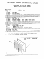
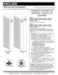
ALL MODELS: Decorator Face Panel Colors
Various Face Panel colors may be used on all models. All
are constructed of heavy gauge steel with your choice of
colored enamel paint finish.
4915
4916
4917
4918
(Almond)
(Black)
(Red)
(white)
NOTE
Kits are identified on their carton by the manufacturing
number 4901, 6901 and 2901 respectively.
Installing
Your Wall Furnace
The following steps are all needed for proper installation
and safe operation of your furnace. If you have any doubts
as to any requirements, check with local authorities.
Obtain professional help where needed.
Locating
All of CHECKS AND ADJUSTMENTS in the Start-Up
Procedure on page 17 are vital to the proper and safe
operation of the furnace. Be sure they are done.
Wall Furnace
The furnace is installed between 2 x 4 inch wall studs
spaced on 16 inch centers or stud space can be framed
in to 16 inches. See page ft (Fig. 9).
When furnace is properly installed with legs resting on
floor plate, it sets the dimension from the face panel
to the bare floor. (21/2inches approximately depending
on the thickness of floor plate).
4.
Consider the following points before attempting to install
the furnace.
A protective barrier (metal or wood), cut to match width
and depth of furnace, should be used to cover over any
floor coverings such as carpet or sheet vinyl that might
be finished off under the furnace.
CAUTION
Do not make cut-outs in wall or ceiling before checking in the attic for ceilingjoist locations and proposed
venting.
1. Place the furnace near the center of the space to be
heated for good air circulation. Do not put it behind a
door or draperies. Do not install it in a closet, alcove,
hallway or other confined space where the furnace
could be isolated by closing doors to the heated space.
Do not locate the furnace where a door could swing
over the front panel, or where circulation could be
retarded by furniture or cabinets.
For large homes or homes with spread-out floor plans,
two or more furnaces are recommended.
MINIMUM
MIN,
APPROX.
L__ BARE
Be sure that gas piping and electrical wiring can be
brought to the location. See sections covering piping
and electrical wiring for your type of furnace mounting.
(Electrical wiring only required for optional blower
accessory.)
HOT SPOTS:
Concealed pipes or
ducts
Fireplaces
Registers
TV sets
Radios
Lamps
Direct sunlight
Kitchen
RECESS DEPTH
OF SINGLE
MODELS IS 41/£'
"_
After picking a location, inspect the wall, floor, attic and
roof areas. Make sure there are no pipes, wiring,
bracing, etc., that would interfere with furnace or vent
installation.If required move them or pick a new location.
Avoid the following:
NOTE:
MAXIMUM
2-1/2
To provide adequate clearance and service access, the
front of the furnace must face the open room. Do not
place obstructive furniture closer than four feet to front
of cabinet.
If your furnace is a wall thermostat model, locate the
thermostat about 5 feet above the floor on an inside wall
where it will sense the average room temperature.
4" MIN. TO
CLOSEST
SIDE WALL
WALL
1
.
,
:URNACE
I
5. The side of the furnace may be as close as 4 inches
to a wall. The recessed portion may have 0 inch
clearance to combustible material.
SPACE
CEILING
16"
NOTE
At no time should the dimension from the bottom of the
face panel to the protective barrier be less than 11/2
inches.
,
T MIN.
& Thermostat
FLOOR
2. Check the minimum spacing needs as shown in Fig. 1.
3. The top of the furnace must be at least 16 inches from
the ceiling.
COLD SPOTS:
Concealed pipes or
ducts
Stairwells-drafts
Doors-drafts
Unheated rooms on
other side of wall
DEAD SPOTS:
Behind doors
Corners and alcoves
After picking a location that meets the requirements make
sure there are no pipes, wiring, or anything else that would
interfere with thermostat installation. If required, move
them or pick a new location.
I
WARNING: DANGER OF PROPERTY DAMAGE, BODILY INJURY OR LOSS OF LIFE. DO NOT INSTALL FURNACE
IN ANY AREA WHERE OXYGEN IS IN USE.
--6--
I
I
Combustion
& Ventilation
Air
WARNING
WARNING
DANGER OF ILLNESS
BODILY INJURY OR DEATH
THE FURNACE AND ANY OTHER FUEL BURNING
APPLIANCE MUST BE PROVIDED WITH ENOUGH
FRESH AIR FOR PROPER COMBUSTION AND
VENTILATION OF FLUE GASES. MOST HOMES
WILL REQUIRE THAT OUTSIDE AIR BE SUPPLIED
INTO THE FURNACE AREA.
DANGER OF PROPERTY DAMAGE,
BODILY INJURY OR DEATH
EVEN WHEN HOUSE MEETS REQUIREMENTS
FOR UNCONFINED SPACE WITH ADEQUATE AIR
INFILTRATION IT IS RECOMMENDED THAT A
FRESH AIR INTAKE BE INSTALLED TO LESSEN
THE POSSIBLE DANGERS FROM ANY FUTURE
CHANGES ON THE HOME,
The high cost of energy for home heating has brought
about new materials and methods used to construct or
remodel most current homes. The improved construction
and additional insulation has reduced the heat loss and
made these homes much tighter around windows and
doors so that infiltrated air is minimal. This creates a problem to supply combustion and ventilation air for gas-fired
or other fuel burning appliances. Any use of appliances
that pull air out of the house (clothes dryers, exhaust fans,
fireplaces, etc.) increases this problem and appliances
could be starving for air.
Ducts must have the same cross-sectionalarea as the free
area of the openings to which they connect.
The minimum dimension of rectangular air ducts must not
be less than 3 inches in length or 3 inches in height.
LOUVERS/GRILLES AND SCREENS
COVERING FREE AREA OPENINGS
If screen is used to cover opening(s), it must not be smaller
than 1/4inch mesh. Use the free area of a louver or grille
to determine the size opening required to provide the free
area specified. If the free area is not known, assume a
20% free area for wood and a 60% free area for metal
louvers or grilles.
The combination of a tight energy efficient home with the
use of exhaust fans, fireplaces, clothes dryers, and gas
appliances results in more and more air being drawn from
the house until fresh air may be sucked into the house
down the furnace flue or fireplace chimney. Carbon
monoxide can be the result. Carbon monoxide or "CO"
is a colorless, odorless gas produced when fuel is not
burned completely or when the flame does not receive
sufficient oxygen. Automobiles, charcoal, wood fires and
improperly vented or air-starved coal, oil and gas furnaces
or other appliances can produce carbon monoxide.
EXAMPLE 1. FURNACE LOCATED IN
UNCONFINED SPACE,"
*An unconfined space must have a volume of a minimum
50 cubic feet per 1000 Btuh of total of all appliances in
area. Adjoining rooms may be included only if there are
no doors between the rooms, or if special provisions are
made such as ventilation grilles installed between connecting rooms.
Be aware of these air starvation signals:
Fig. 4, page 8 shows the minimum area in square feet,
based on 8 foot ceiling heights, required for different Btuh
input ratings.
A. INFILTRATION AIR
1. Headaches, nausea, dizziness
2. Excessive humidity -- heavily frosted windows, moist
"clammy" sensation.
3. Fireplace smokes, won't draw
4. Furnace flue backs up
If your furnace is in an open area unconfined space*)
the air that leaks through the cracks around doors
and windows may be enough for combustion and
ventilation air. The doors should not fit tightly. The
cracks around windows should not be caulked or
AIR REQUIREMENTS
The requirements for providing air for combustion and ventilation are listed in the National Fuel Gas Code NFPA
54/ANSI Z223.1 (in Canada: CAN/CGA B149). Most homes
will require that outside air be supplied to the furnace area
by means of ventilation grilles or ducts connecting directly to the outside or spaces open to the outdoors such as
attic or crawl space. The only exception is when the furnace area meets the requirements and definitions for an
unconfined space with adequate air filtration.
All air openings and connecting
the following:
weather stripped.
VENT PIPE
DRAFT
HOOD
__1
,A,C.
ducts must comply with
] !
IF THE FURNACE IS INSTALLED IN AN AREA WITH
ANOTHER GAS APPLIANCE(S),
THE TOTAL INPUT
RATING OF ALL APPLIANCES MUST BE CONSIDERED
WHEN DETERMINING THE FREE AREA REQUIREMENTS FOR COMBUSTION AND VENTILATION AIR
OPENINGS.
TYPICAL
WATER
HEATER
--7--
\DRAFT
HOOD
WALL
FURNAC
E
OPENING
Combustion
To determine if infiltration
following checks:
& Ventilation
air is adequate, perform the
Air (Con't)
Provide an opening(s) having a total free area of 1 sq.
inch per 4000 Btuh of the total of all appliances. The
required area is shown in Fig. 7, page 9.
1. Close all doors and windows. 11you have a fireplace, start a fire and wait until flames are burning
vigorously, (or flue damper can be closed),
FRESH AIR DUCT
2. Turn on all exhausting devices, such as:
- kitchen and bathroom exhaust fans.
HOLES
- water heaters (gas and electric).
3. Turn on all vented gas appliances,
FROM
VENTILATED
ATrJc INTO STUD
SEE FrG. 8
SPACE
such as:
- heating equipment (includes any room heaters)
- water heaters.
4. Wait ten (10) minutes for drafts to settle down.
5. Check for drafthood spillage at each appliance.
(Hold a lighted match 2 inches from draft opening.
See Fig. 2, page 7).
B. No Spillage
Match flame pulls toward drafthood -- this indicates
sufficient infiltration air. Return exhausting devices and
appliances to the condition you found them.
AIR GRILLE
TO STUD
SPACE
C. Drafthood Spills
If there is spillage at a drafthood (match goes out or
flame wavers away from drafthood):
I
1. Check for plugged flue connectors and chimneys.
Check and repair stoppage and test again.
HOLES
FROM
CRAWL SPACE
SEE FIG 7
2. If you have a fireplace, open a window or door near
the fireplace and then check for spillage.
HOLE IN BOTTOM OR
BACK OF FURNACE
INTO OPEN STUD SPACE
a. If spillage stops, do not use the fireplace without
a nearby window or door open until you can
supply fresh air by a permanent duct.
OR CRAWL
12" MAXFROM
FLOOR
VENTILATED
INTO
STUD
SPACE
SPACE
1. Duct must terminate at a point not more than 1 foot
above the floor.
3. If you have kitchen and bathroom exhaust fans, turn
them off and check for spillage.
a. If spillage stops, do not use exhaust fans until
you can supply fresh air by a permanent duct.
Circuit breakers for fans should be turned off if
possible.
2. Duct size must be at least I inch of free area for each
4000 Btuh of input of all appliances in area.
MINIMUM
4000 Btuh Per
Square Inch
Opening
WARNING
DANGER OF ILLNESS,
BODILY INJURY OR DEATH
DRAFTHOOD SPILLAGE WITH UNOBSTRUCTED
VENTS, INDICATES THAT ADDITIONAL
AIR
MUST BE BROUGHT INTO THE STRUCTURE
FROM THE OUTSIDE. KEEP A WINDOW OPEN
(MINIMUM 2 INCHES) NEAR THE APPLIANCE
UNTIL A PERMANENT AIR DUCT IS INSTALLED.
Round
Duct
4"DIA.
4"DIA.
4"DIA.
4"DIA.
4"DIA.
41!2"DIA.
Rectangular
Duct
3"X3"SQ.
3"X3"SQ.
3"X4"SQ.
3"X4"SQ.
3"X5"SQ.
3"X5"SQ.
AREA IN SQUARE
FEET
Input
*Unconfined
Space
Min. Area In Sq. Ft,
8' Ceiling Height
30,000
35,000
40,000
45,000
50,000
60,000
188
219
250
281
312
375
Max. Btuh
*Can be two or more rooms joined by ventilation grilles.
4. Spillage means air starvation and a fresh air duct
or air intakes must be installed to provide air directly to the furnace or other gas appliance.
D. If spillage exists or when the furnace is in a building
of tight construction where the windows and doors are
weatherstripped, air for combustion and ventilation
must be obtained from outdoors or space open to the
outdoors.
--8--
EXAMPLE 2. FURNACE LOCATED IN
CONFINED SPACE
If furnace is installed in a confined space, it must be provided with free air for proper combustion and ventilation
of flue gases by one of the following methods:
Combustion
& Ventilation
A. All Air From Inside Building:
If the confined space adjoins an unconfined space as
defined in EXAMPLE 1, provide two permanent openings,
one within 12 inches of the top and one within 12 inches
of the bottom of the room connecting directly to unconfined space. Each opening must have a free area of at least
100 square inches or 1 square inch per 1000 Btuh combined input of appliances in one room if combined input
exceeds 100,000 Btuh.
Air (Con't)
outdoors or spaces open to outdoors such as attic or crawl
spaces.
Provide two permanent openings, one within 12 inches of
top, one within 12 inches of bottom of room connecting
directly, or by using ducts, with the outdoor or areas open
to outdoors.
If opening connects directly to, or with vertical ducts, the
free area of each opening must be at least 1 square inch
per 4000 Btuh combined input of appliances in area.
If horizontal ducts are used, the free area of each opening
must be at least 1 square inch per 2000 Btuh combined
input of appliances in area.
WARNING
DANGER OF PROPERTY DAMAGE,
BODILY INJURY OR DEATH
THE ADJOINING UNCONFINED SPACE MUST
HAVE ADEQUATE AIR INFILTRATION AS DEFINED
IN EXAMPLE 1.
FOR EXAMPLE: Your furnace is rated at 50,000 Btu per
hour. The water heater is rated at 30,000 Btu per hour.The
total is 80,000 Btu per hour. You need two grilles, each with
100 square inches of free opening. Metal grilles have about
60% free area, so you need two metal grilles each with
160 square inches of Iouvered area.
FOR EXAMPLE: Your furnace is rated at 50,000 Btu
per hour. The water heater is rated at 30,000 Btu per
hour. The total is 80,000 Btu per hour. You need two
grilles, each with 20 square inches of free opening,
unless connected by horizontal ducts which would require each grille or opening to have a free area of 40
square inches.
3 OR CRAWL SPACE
Refer to Fig. 5, which shows grille installation.
CH_MN[
OR
Using the previous example, the two connecting rooms
plus the closet must equal at least 500 sq. feet to handle
the combined input 50,000 plus 30,000.
GRILLES CONNECTING ROOMS TO
MAKE UNCONFINED SPACE
VENTILATION
GRILLES
TWO
ROOMS
$PAC_
TO
I
OUTLET
GAS
y
VENT
AIR
CONNECTING
MEET
UNCONFINED
==
so
_N
I
I
,I
o-=
200
SO
PNLEI
IN
AIR
MINIMUM
BETWEEN
LARGE
ROOMS
*Openings for inlet or outlet air should not be made into
attic area if attic is equipped with a thermostat controlled
power vent.
FREE AREA IN SQ. INCHES
EACH OPENING (FURNACE ONLY)
BASED ON ONE SQ. INCH PER 4000 BTUH
100
So
IN
1<[ COMMENOt
FRESH
rPilO
AIR
CRAWL
_ U_NACE
OR
IN
$PAC_
W_IH
Sq. Inch
of Opening
30,000
35,000
40,000
45,000
50,000
60,000
7.5
8.75
10.0
11.25
12.5
15.0
1V="
2"
3"
7
8
9
10
11
13
4
5
5
6
6
8
2
2
3
3
3
4
_N
AREA
CLOS[T
Btuh/Input
Furnace
O
DUCT
Req'd Number of Holes
Sill or Header Plates
WAIER
HLA1FR
B. All Air From Outdoors:
If confined space doesn't adjoin an unconfined space
(defined in EXAMPLE 1) then air must be provided from
--9--
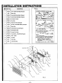
Recessed
Mount
NOTE:
Model Series 25096 and 35096. The maximum recess
depth, from rear of furnace forward is 41/=''.
Installation
rear outlet plasterground at the same time you install the
header plate. For existing construction, make necessary
cutout and install the plasterground just before you install
the furnace. See instructions packed with kit and Fig. 8.
FIND THE STUDS AND CEILING JOISTS
Use a stud Iocator or small finishing nails. Repeatedly drive
and remove a nail into the wall in the area of the stud until
it is located. Then find the inside edge of the stud. Leave
the nail at this location.
The other stud should be about 141/2inches from the one
found. Drive finishing nails on the inside of this stud. Drew
wall cut out to required size as shown in Fig. 8. If wall studs
are not on 16 inch centers see "Close Off Stud Space."
Do not allow wall finish material to project into the furnace
recess.
Do not install rear outlet register where grille may be blocked by door swing, curtains or any other obstruction.
GAS SUPPLY OPENING
A hole must be drilled for the gas line. See Fig. 8 for alternate gas line openings.
Decide whether the gas line witl come through the floor
or wall.
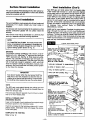
CUT WALL OPENING (See Caution on page 6)
Drill a 11/2 inch hole in wall or floor (Fig. 8) as needed.
All models: Cut wall opening 14-3/8 inches wide and 66-1/8
inches high measured from top of floor plate. See Fig. 8.
All corners must be square.
INSTALLATION OF REAR OUTLET REGISTER (If Used)
The optional rear outlet register 6901 can be installed
when furnace is recessed. In new construction, install the
CLOSE OFF STUD SPACE (If Required)
If studs are not on 16 inch centers, cut the hole for the
furnace next to an existing stud and frame in the other side
using a 2x4 and spacer blocks as required. See Fig. 9,
page 11.
HEADER PLATE AND GAS SUPPLY OPENINGS
115V. OUTLET
TO TOP
OF HEADER
PLASTERGROUND
FOR
OPTIONAL
REAR REGISTER
PLASTERGROUND
TOP
BOTTOM
HEADER NAILING
FLANGE
NAIL
FLANGE
MODELS
2509611
2509612
2509621
2509622
LOCATION
AND
PLATE
3509611
3509612
3509621
3509622
ALTERNATE
62V4
FINtSHEO
FLOOR
GAS
--10--
Recessed
Mount
Installation
(Con't)
CEILING PLATE SPACERS
RECESSED MOUNT
CLOSE OFF STUD SPACE
14 3/8
PLA'flE
I_-
EXISllNG STUD
I]I
CEILING
PLATE
SPACERS
NAILED
IN BE'nNEEN
CEILING
PLATES OR
ACROSS
FACE IF
ACCESSIBLE
NEW STUD
III
_S_NG
S'PJD -_
_A_
I
[ II
BLOCKS
•.-- 14--3/8"
[
FLOOR
III
HI
III
CUT PLATE OPENING (RECESSED VENTING)
OPTIONAL ELECTRICAL OUTLET
Cut away the ceiling plate between the studs where the
furnace is to be installed. Work from the top in the attic.
If there is no access to the top, remove the wall covering
between the two wall studs, all the way to the ceiling. Work
through this opening.
7
Cut out the entire plate so the plate edges will be even
with the inner face of the 2x4 studs (Fig. 10).
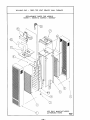
INSTALL VENT BASE PLATE (HOLD-DOWN
PLATE)
BLOWER AGCT
Position base plate on top of header plate and fasten with
screws. Note: These items are included in Vent Kit 9901.
HEADER PLATE (VENT SUPPORT)
Measure up 621/4 inches from the top of floor plate. Place
a mark on each stud at this distance. See Fig. 8, page 10.
Place the header plate between the studs with the lower
edges even with marks on the studs. Make sure header
plate is level.
All models: Locate rear edge of nailing tabs at back of 2x4
stud which will center the vent collar in the wall. Nail
header plate to studs. See Fig. 8, page 10.
INSTALL CEILING PLATE SPACER (RECESSED MOUNT)
Refer to Fig. 10.
Two ceiling plate spacers are in the B/W Vent Kit. They
must be fastened along each long edge of the ceiling hole
to hold the oval vent pipe in the center of the hole.
Nail the ceiling plate spacers either across or in between
the cut out section of ceiling plate. If nailed between, end
must be bent at 90 degrees.
Ceiling plate spacers preserve structural strength and position oval vent pipe in the center of the cut out opening.
No electric power is required unless furnace is equipped
with an optional blower. Do not connect 115V service line
to the gas control valve or wall thermostat.
ELECTRICAL OUTLET (Optional)
If you are installing optional blower accessory with the furnace, rough-in a 115V electrical outlet as shown in Fig. 11.
--11 m
62V4
,
%
Surface
Mount
Installation
Vent Installation
The use of optional Free Standing Kit No. 4901 allows furnace to be mounted on the surface of a wall. See detailed
instructions packed with kit.
Vent Installation
The vent installation must comply with all local codes and
ordinances. If in doubt, consult your local codes or
inspector.
The furnace vent must be directed to the outdoors so that
harmful combustion gasses will not collect inside the
building.
This furnace must not be connected to a chimney flue
serving a separate solid-fuel burning appliance.
NOTE:
U.L. listed B/W Vent Kit 9901, You must provide other
items, not contained in kit, necessary to complete your
specific venting situation through the roof. Refer to
typical venting system shown in Fig. 12.
(Con't)
Type B/W gas vent shall extend from the header plate
of the vented wall furnace to a point above the highest
ceiling plate within a stud space through which the vent
passes, without any offsets or crossovers therein. After
a type B/W gas vent passes through the highest ceiling
plate within a stud space above the furnace which it
serves, the vent system may be completed with a type B
gas vent, of the same manufacturer (do not mix brands
of pipe), and offsets or breakovers shall not be greater than
45 degrees from vertical.
Refer to (UNIFORM
MECHANICAL CODE).
Install oval to round adapter. Complete the piping extending it through the roof. Use a 4 inch round double wall
(Type B) vent pipe, roof flashing, storm collar,and vent top
as shown. The vent cap must be at least 2 feet higher than
any point that is within 10 feet horizontally of the vent cap.
There must be at least 1 inch clearance between the vent
pipe and any combustible material.
TYPICAL VENT INSTALLATION
WARNING
This product is design certified by A.G.A./C.G.A. to be installed with a U.L. listed type "B" approved vent and type
"B/W" approved vent. See Fig. 12. Older style terra-cotta,
transite, clay, concrete or masonary type vent pipe cannot be used with this appliance. This older type vent pipe
will not heat fast enough to establish a draft, which will
result in improper venting of combustion products. Consequently, this could cause the vent safety control system
to shut down the furnace.
"dYQtTCAP MUST BE MINIMUM 2 FEET
HIGHER 1HAN ANY POINT WI1HIN 10 FEET
0F '4ENT CAP
CAP
STORM
ROOF
HEIGHTFROMHEADER
PLATETO VENTCAPTOP
MUSTBE S F£_ MINIMUM
1 INCHMIH. CLEARANCE
TO COMBUSllBLES
_,= USTE_
4." ROUNDB VISIT
$ OVALTO ROUNDADAPTER
$ OVALB/_V
IMPORTANT
Area above header within the stud space MUST be
kept clear of any attic insulation to allow the free circulation of air around oval vent piping. In some areas
the building code requires the use of an attic shield.
VENT (DOIJBLE
WALL)
$ PLATESPACER-
(RECESSED
MOUNT)
2 R£Q'D
* eASE PLATE (HOLD-DOWN) OR
STARTERPLATE SCREWEDDOWN
TO HEADER PLAIT-,,
NOTE
The B/W vent must extend through the ceiling and roof
terminating at least 12 feet above the finished floor on
which the furnace rests.
First vent pipe offset (if required) must not be any closer
than 2'-0" from header plate.
NOTE
HEADER PLATE AND GASKETS
PRO_/1D£D WITH FURNACE
TAKE CARE NO'r TO DISllJRB
_
GLUED TO
OF HEADER. _
MA'r_41AL
INSTALL FURNACE VENT
(RECESSED MOUNT)
Lower a 4 foot length of oval, double wall vent pipe through
the place spacers to the hold-down plate.
Push the vent pipe into the hold-down plate until it is completely seated. (Hold-down cleat will engage the groove
in the vent pipe.)
MUST NOT BLOCK FLUE Ex'nsNsICH \
* CONTAINED IN OVAL B/W
(STARTER) VENT KIT
NO. 9901
"° NOT PROVIDED
AVAILABLE
WITH KITS
50,000 BTUH FURNACE
AND HEADER NOT SHOWN.
NOTE:
FLUE COLLAR GASKET, NOT REQUIRED ON MODELS 5009611,
5009612, 5009621 & 5009622
COMPLETE THE VENTING
Refer to Fig. 12.
--12--
Mount
POSITION
f
The Furnace
URING FURNACE
LEGS NEAR FLOOR PLATE
FURNACE
BOTTOM
OF FURNACE
B/W VENT
NAIL FURNACE
LEG TO STUD OR
(SEE DETAIL
BELOW)
LEG
_
FLOiR
PLATE
MODELS
ANGLE
2509612
2509622
3509612
3509622
AND
_FLOOR
PLATE
2509611
2509621
IMPORTANT
AVOID NAILING THE LEGS SO TIGHTLY THAT IT
DISTURBS THE INNER FURNACE CASINGS. DO
NOT TRY TO FORCE THE FURNACE INTO A
SMALLER-THAN-SPECIFIED
RECESS.
3509611
3509621
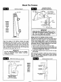
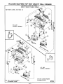
Clear the recess of a!l debris, remove any wood
plastergrounds. Stand furnace in front of recess, holding
the furnace body at an angle. Insert flue collar into opening in the header plate and raise furnace carefully. See
Fig. 13. Swing bottom of furnace into recess with front
edges of legs flush with 2x4 floor plate. Nail through legs
into studs or floor plate. See Fig. 14.
DO NOT DAMAGE GASKET GLUED TO UNDERSIDE OF HEADER PLATE WHEN PLACING
IMPORTANT
FURNACE IN WALL.
REMOVING
INNER
SHIELD
_
OF
KNOCK-OUT
I
REAR OUTLET KIT INSTALLATION (If Used)
CAUTION: Do not install rear outlet kit where grille may be
blocked by door swing, curtains or any other obstruction.
If Rear Outlet Register 6901 is used, the following procedure must be complete before placing furnace body into
wall recess. See Fig. 15. Attach speed nuts to outer shield,
and remove knock-out plates as follows:
1. Punch in lower corners with screwdriver blade.
2. Break knock-out side and bottom connecting tabs: hold
screwdriver blade sideways against tab and strike head
of screwdriver lightly with a hammer.
3. Swing plate outward; bend it back and forth to break
the top tabs.
After furnace is in position, install rear outlet as shown in
Fig. 16. Have damper in open position when inserting
assembly. Secure register assembly to speed nuts with
machine screws furnished.
PLATES
MOUNTING
FURNACE
10-24 SPEED
NUT
HOLD SCREWDRIVER SIDEWAYS AGAINST
TABS ANO STRIKE
LIGHTLY WITH HAMMER
/
MODELS
2509612
2509622
3509612
3509622
AND
2509611
2509621
3509611
3509621
SHIELDS
PLASTERGROUNO-
ASSEMB_
--13 m
REAR OUTLET
Gas Supply and Piping
Gas control valve, within the furnace, is shipped with a
sealed cover gas inlet tapping. Do not remove seal until
ready to connect piping.
WARNING
DANGER OF PROPERTY DAMAGE,
BODILY INJURY OR DEATH.
MAKE SURE THE FURNACE IS EQUIPPED TO
OPERATE ON THE TYPE OF GAS AVAILABLE.
MODELS DESIGNATED AS NATURAL GAS ARE TO
BE USED WITH NATURAL GAS ONLY. FURNACE
DESIGNATED
FOR USE WITH LIQUEFIED
PETROLEUM (L.P.) GAS HAVE ORIFICES SIZED
FOR COMMERCIALLY
PURE PROPANE GAS.
THEY CAN NOT BE USED WITH BUTANE OR A
MIXTURE OF BUTANE AND PROPANE.
use compound resistantto action of liquefied petroleum
gases.
Use ground joint unions.
4. Install a drip leg (sediment trap) to trap dirt and
moisture before it can enter the gas valve. Nipple must
be a minimum of 3 inches long. See Fig. 17.
5.
Install a manual shut-off valve.
3.
6. Provide a 1/8 NPT test gauge connection immediately
before the gas supply connection to the furnace.
GAS CONNECTION
If installation is for L.P gas, installer use two-stage regulator and make all connections from storage tank to furnace.
Use two pipe wrenches when making the connection to
the valve to prevent turning of, or damage to gas valve.
GAS SUPPLY
MINIMUM gas supply pressure for NATURAL GAS to the
furnace control valve is 5 inches water column. For natural
gas, it must not be more than 7 inches.
Connection between shutoff valve and burner control
assembly can be made with an A.G.AJC.G.A. design certified flexible connector if allowed by local codes.
Tighten all joints securely.
Minimum gas supply pressure for L.P. Gas to the furnace
control valve must be at least 11 inches water column. It
must not exceed 13 inches.
Gas pressures and input to the burners must not exceed
the rated input and pressure shown on the rating plate.
On Natural Gas the manifold pressure should be 4 inches
water column. The manifold pressure should be 11 inches
water column for L.R Gas. See page 17 for operation
above 2000 feet altitude.
DROP
I
I
PIPED
I11 o,,
SUPPLY
HO_IZONTAL
TEE
FITTING_
Orifice change may be required to suit gas supplied.
Check with your WILLIAMS service department.
R_SER
_
PIPED
3,n i76 2 mini
mINIMUM
+-=NIPPLE
GAS
r_ANUAL SHUT OFF
<--- CAP
VALVE
ORIFICE SIZES
SUPPLY
Furnace Technical Information, Page 25, shows the correct orifice sizes for the different input ratings when using
Natural or L.P. Gas.
i
TEE
_FITTING
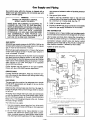
GAS PIPING
The gas supply line must be of an adequate size to handle
the BTU/HR requirements and length of the run for the
unit being installed.
Determine the minimum pipe size from Fig. 18, page 15,
basing the length of the run from the gas meter or source
to the unit.
All piping must comply with local codes and ordinances
or with the National Fuel Gas Code (ANSI Z223.1 NFPA
No. 54), whichever applies. (In Canada: CAN/CGA B149.)
Refer to Fig. 17 for the general layout at the unit. It shows
the basic fittings needed.
The following rules apply:
1. Use new, properly reamed pipe free from chips such
as steel or black iron pipe and fittings or other approved
by local codes.
2. Do not thread pipe too far. Valve distortion or malfunction may result from excess pipe within control.
Apply moderate amount of good quality dope to pipe
only, leaving 2 end threads bare. If LP gas installation,
--14--
PROPER
2 IMPERFECT
THREAO
PIPt.
RIGHT
PIPING
CONTROL
LENGTH
PRACTICE
USE
LEAVE
MODiERATE
2 EI_O
AMOUNT
YHREADS
OF
BARE
DOPE
Gas Supply
CHECKING
and Piping (Con't)
THE GAS PIPING
GAS PIPE SIZES
Test all piping for leaks. When checking gas piping to the
furnace with gas pressure at less than 1/2 PSI, shut off
manual gas valve for the furnace, if gas piping is to be
checked with the pressure at or above 1/2PSI, the furnace
and manual shut off valve must be disconnected during
testing. (SEE WARNING BELOW.) Apply soapsuds (or a
liquid detergent) to each joint. Bubbles forming indicates
a leak. Correct even the slightest leak at once,
NATURAL GAS
PiPE CAPACITY - BTU PER HOUR
(INCLUDES FITTINGS)
PIPE SIZE.
LENGTH
OF
PIPE-FT.
20
40
60
WARNING
DANGER OF PROPERTY DAMAGE,
BODILY INJURY OR DEATH.
NEVER USE A MATCH OR OPEN FLAME TO TEST
FOR LEAKS. NEVER EXCEED SPECIFIED PRESSURES FOR TESTING. HIGHER PRESSURES MAY
DAMAGE THE GAS VALVE AND CAUSE OVERFIRING WHICH MAY RESULT iN HEAT EXCHANGER FAILURE. LIQUID PETROLEUM (L.P.)
GAS IS HEAVIER THAN AIR AND IT WILL SETTLE
IN ANY LOW AREA, INCLUDING OPEN DEPRESSIONS AND IT WILL REMAIN THERE UNLESS
AREA IS VENTILATED.
NEVER ATTEMPT STARTUP OF UNIT BEFORE
THOROUGHLY VENTILATING AREA AND SMELLING NEAR THE FLOOR FOR GAS ODOR.
314"
190.000
130,000
105,000
I"
350,000
245,000
195.000
L.P. GAS
PIPE CAPACITY
LENGTH
OF
PIPE-FT.
2O
4O
60
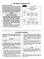
Thermostat
- BTU PER HOUR
(INCLUDES FITTINGS)
I/2"
189,000
129,000
103.000
j
3/4"
393,000
267.000
217,000
I"
732,000
504,000
409,000
Installation
Models 2509611, 2509612, 3509611, 3509612, 5009611 and
5009612 utilize a built-in thermostat control system
operated by a heat sensing bulb located in the burner
compartment.
I
I/2"
92,000
63,000
50.000
I
IMPORTANT
Handle the bulb with care. Do not kink the connecting tubing.
Models 2509621, 2509622, 3509621, 3509622, 5009621
and 5009622 are operated by a millivolt type thermostat.
Current to the thermostat is supplied by the pilot generator.
Anticipation settings are not required.
1. If an old thermostat is being replaced and is in a
satisfactory location and the wiring appears to be in
good condition, use existing wiring. If in doubt, use new
wire.
2. If a new location is chosen or if this is a new installation, thermostat cable must first be run to the location
selected. All wiring must agree with local codes and
ordinances. These instructions cover bringing the wire
down from the attic but it can be run from a basement
or crawl space using similar methods.
3. Before drilling hole in wall at selected location, drive
a small finishing nail through the ceiling in the corner
m15m
of the wall and ceiling above the thermostat location.
Pull the nail out and push a small stiff wire through the
hole so it can be found in the attic. Drill a 1/2-inch hole
through the ceiling wall plate (see Fig. 19 page 16).
4,
5,
Probe for obstructions in the partition. Then drill a
1/2-inch hole through wall at selected location for
thermostat.
From the attic, feed the thermostat cable or a stiff wire
through wall until even with thermostat location.
6. Snag thermostat cable through hole and pull cable
through hole in wall so that 6 inches of cable protrudes.
7. Route cable to wall furnace.
CAUTION
Do not run wire behind flanges of Header Plate or
in any location where it might be damaged. Avoid
splicing thermostat wire unless the spliced wires are
properly cleaned, soldered and taped.
NOTE
Use #18 Ga. wire as supplied for maximum length of 20
feet. If longer length is needed, use #16 Ga. for maximum
length of 25 feet.
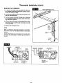
Thermostat
MOUNTING
Installation
(Con't)
THE THERMOSTAT
ROUTE THERMOSTAT CABLE
1. To remove thermostat cover, squeeze both sides and
lift. Carefully remove and discard the packing tab protecting the switch contacts.
2. Connect thermostat wires to the terminal screws on the
back of thermostat base.
3. Push any excess wire back through hole in wall and
plug hole with insulation to prevent drafts from affecting thermostat operation.
4. Be sure to level thermostat for best appearance, fasten
thermostat base to wall through mounting holes with
screws provided.
5. Replace the thermostat cover.
SMALL
FINISH
NAIL
NOTE
TO
EOCATE
HEADER
Refer to installation instructions packed in the thermostat carton if you have any doubt about the above procedures.
1HERMOSTAT
CABt_
Connect thermostat wire, previously run to burner compartment from thermostat, to control valve as shown in
Fig. 20.
THERMOSTAT
GENERATOR
GENERATOR
RED-_,
_--WHITE
THERMOSTAT
LIMIT SWITCH
BLUE
KNOB
GREEN KNOB
WILLIAMS
P295000A (OR)
P295001A
"_ WILLIAMS
LIMIT SWITCH
P172100A (OR)
P172200A
--16--
Cabinet
B*'WVENT_
installation
PANEL ATTACHING
SCREW
IG
B/W
!
SCREW
EA SIDE
MODELS
MODELS
2509611
2509612
2509621
2509622
5009611
5009612
5009621
5009622
AND
3509611
3509612
3509621
3509622
BOTTOM
PANEL
MENT (2} SCREWS
EACH SIDE
CASING/
LEGS
PANEL DOOR
(CONTROL)
(CONTROL)
FLOOR
LEGS
PLAlr E
FLOOR
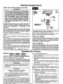
Place panel top over channel on header plate, as shown
in Fig. 21. Press panel tight against wall, and secure it to
header with screw provided in final assembly package.
Open control door at bottom of panel and fasten panel at
each side through slots in flanges with screws provided.
NOTICE
DURING THE FIRST FIRING OF THIS UNIT SOME
SMOKE AND ODOR MAY OCCUR. WE RECOMMEND VENTILATING THE AREA DURING THIS
"BREAK IN" PERIOD. LET FURNACE REACH FULL
OPERATING TEMPERATURE.
Attach handle to panel door with screws provided.
Models 5009611, 5009612, 5009621 and 5009622: Install
second face panel in same manner.
Start-Up
Start the furnace using the procedures
OPERATING YOUR FURNACE.
PLATE
Procedure
in section
WARNING
DANGER OF PROPERTY DAMAGE,
BODILY INJURY OR DEATH.
LIQUEFIED PETROLEUM L.P. GAS IS HEAVIER
THAN AIR AND IT WILL SETTLE IN ANY LOW
AREA, INCLUDING OPEN DEPRESSIONS AND IT
WILL REMAIN
THERE
UNLESS AREA IS
VENTILATED.
NEVER ATTEMPT STARTUP OF UNIT BEFORE
THOROUGHLY VENTILATING AREA.
Check the furnace operation as outlined in the following
instructions. If any sparking, odors or unusual noises are
encountered, shut off electric power immediately. Recheck
for wiring errors, or obstructions in or near fan motor (if
equipped).
CHECK GAS INPUT AND PRESSURES
For furnace located at elevations between sea level and
2000 feet, the measured input must not be greater than
the input shown on the rating plate of the furnace. For
elevations above 2000 feet, the measured input must not
n17--
exceed the input of the rating plate reduced by 4 percent
for each 1000 feet that the furnace is above sea level.
Gas supply pressure and manifold pressure with the
burners operating must also be as specified on the rating
plate.
Type of Gas
]
Manifold Pressure, In. W.C.
Natural
L.R
I
11
4
Rated input will be obtained on 2500 Btu propane at 11
inch manifold pressure and factory-sized orifices. If LP gas
having a different heating value is supplied, orifices must
be changed by a qualified service technician before the
furnace is operated.
CHECK THE MANIFOLD GAS PRESSURE
A tapped opening is provided in the gas valve to facilitate
measuring the manifold gas pressure. A "U Tube"
manometer having a scale range from 0 to 12 inches of
water should be used for this measurement. The manifold
pressure must be measured with the burner and pilot
operating. Any major changes in the flow must be made
by changing the size of the burner orifice. Check with your
WILLIAMS service department for proper orifice sizing.
Start.Up Procedure
(Con't)
CHECK THE GAS INPUT (NATURAL GAS ONLY)
-WARNING
NATURAL GAS HEATING VALUE (BTU PER CUBIC
FOOT) CAN VARY SIGNIFICANTLY, THEREFORE,
IT IS THE INSTALLERS' RESPONSIBILITY TO SEE
THAT BTU INPUT TO THE FURNACE IS ADJUSTED
PROPERLY. FAILURE TO DO SO COULD CAUSE
HEAT EXCHANGER FAILURE, ASPHYXIATION,
FIRE OR EXPLOSION, RESULTING IN DAMAGE,
BODILY INJURY OR DEATH. REFER TO THE NATIONAL FUEL GAS CODE (NFPA-54) TO BE SURE
THE FURNACE IS BURNING FUEL AT THE PROPER RATE.
TOP
V1EW
SLOTTING
IN EIURNI_
BOOY
GENERATOR
"IHERMOCOUPLE
Underfiring could cause inadequate heat, excessive condensation or ignition problems. Overfiring could cause
sooting flame impingement or overheating of heat
exchanger.
FRONT
_EW
Before starting natural gas input check, obtain heating
value of gas (BTU per cubic foot) at standard conditions
from your local supplier. This factor is used in "Check the
Gas Input" section and procedure.
This measured input must not be greater than the input
indicated on the rating plate of the furnace.
To measure the input using the gas meter, proceed as
follows:
Step 4: Relight all other appliances turned off in step 1
above. Be sure all pilot burners are operating.
Step 1: Turn off gas supply to all other appliances except
the furnace.
CHECK PILOT BURNER
The pilot flame must envelop 1/2 to 5/8 inch of thermocouple or generator. See Fig. 22. Pilot flame is preset at
the factory, so ordinarily does not require field adjustment.
If adjustment is needed, see page 24.
Step 2: With the furnace operating, time the smallest dial
on the meter for one complete revolution. If this is a 2 cubic
foot dial, divide the seconds by 2; if it is a 1 cubic foot dial,
use the time in seconds as is. (3,600 = Sac. Per Hr.) This
gives the seconds per cubic foot of gas being delivered
to the furnace.
CHECK THERMOSTAT
Check thermostat operation. When set above temperature shown on the thermostat, the main burner should light.
Make certain the thermostat turns off the furnace when
room temperature reaches the selected setting and starts
the furnace when room temperature falls a few degrees.
Step 3: Assuming natural gas with a heating value of 1000
Btu per cubic foot and 34 seconds per cubic foot as determined by step (2), then:
Input: 1,000 X 3,600 + 34 = 106,000 Btu Per Hour
Operating
Your Furnace
MODELS
2509611 ; 3509611 ; 5009611
2509612;
3509612;
5009612
NOTE: SEE PAGE 21 FOR MODEL INFORMATION NOTE.
SAFETY, OPERATING AND SHUTDOWN
All models listed above are equipped with a Williams gas
control valve part number P322051; P322052 (see page
19) or part number P295100A; P295101A (see page 20).
WARNING
DO NOT STORE OR USE GASOLINE OR OTHER
FLAMMABLE LIQUIDS OR VAPORS NEAR THE
FURNACE.
/
|
J
WARNING'
DANGER OF PROPERTY DAMAGE,
BODILY INJURY OR DEATH
IF THE FURNACE OVERHEATS OR FAILS TO
SHUT OFF, CLOSE MANUAL GAS VALVE FOR
THE FURNACE BEFORE TURNING OFF ELECTRIC POWER FOR THE FAN.
Your furnace is equipped with a 100% safety pilot which
will shut off the gas supply in case the pilot is not burning
or functioning properly. Make sure the pilot is adjusted
properly and that the thermocouple connection at the control valve is tight. If furnace will not stay lit, call your local
clas utility or qas sul_plier.
--18--
The furnace operates like this:
1. Cool air around built-in sensing bulb automatically
turns on the burner.
2. Heat builds up in the furnace and starts the fan (if
equipped). The heated air comes out the front panel
louvers.
3. When the built-in sensing bulb is sufficiently heated
by the warmer room air it automatically turns off the
main burner.
4. The fan runs until the heat is removed from furnace,
then it will turn off (if equipped).
NOTE: On new installation the gas lines will be filled with
air and may take several minutes to establish the pilot
flame.
--MANUAL
SPARK
IGNITER
USAGE:--
If furnace is equipped with a manual spark ignitor,
follow these next steps:
1. Review the operating instructions on preceding
pages.
2. When instructed to "light the pilot" depress red
button located on the burner pan for pilot ignition.
If necessary, depress red button several times for
pilot ignition.
3. If pilot fails to ignite or a spark is not present while
actuating red button, follow steps 5 through 10
listed in operating instructions.
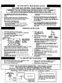
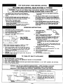
FOR YOUR SAFETY,
WILLIAMS
READ
GAS CONTROL
BEFORE
LIGHTING
VALVE P322051
& P322052
I
I WARNING:
If youcausing
do not property
follow these
Instructions
a firs
may result
damage,
personal exactly,
injury or
lossorofexplosion
life.
A.
This appliance
has a pilot which must be Ilghfed by
hand. When lighting the pilot, follow these instructions
exactly.
B.
BEFORE LIGHTING
smell around the appliance area
for gas. Be sure to smell next to the floor because some
gas is heavier than air and will settle on the floor.
• If you cannot
department.
WHAT TO DO IF YOU SMELL GAS
• Do not try to light any appliance.
• Do not touch any electric switch; do not use any
phone in your building.
• Immediately
call your gas supplier from a neighbor's
phone. Follow the gas aupplier's instructions.
OPERATING
1.
2.
3,
4.
5,
@l
@l /
_, I ._
J/"
_.._.J /'_1_'_[
7.
8.
Use only your hand to push In or turn the gas control
knob. Never use tools. If the knob will not push in or
turn by hand, don't try to repair It, call a qualified servIce technician.
Force or attempted
repair may result In •
fire or explosion.
D,
Do not use this appliance if any part has been under
water. Immediately
call • qualified service
technician
inspect the appliance and to replace any pert of the
control system and any gas control which has been
under water.
9.
10.
Push in gee control
knob slightly and turn
counterclockwise
_
to "PILOT."
Push in control knob all the
way end hold in. Immediately
light the pilot.
THERMOCOUPLE
PILOT
BURNER
• If knob does not pop up when released,
stop and
immediately
call your service
technician or gas
supplier.
• If the pilot will not stay lit after several tries, turn
the gas control knob to "OFF"
and call your service
technician or gas supplier.
11. Close pilot observation door, tighten wingnut
Wait five (5) minutes to clear out any gas then smell for
gas, including near the floor. If you then smell gas, stopl
Follow "B"
in the safety information
above. If you don't
smell gas, go to next step.
Loosen wingnut and open the pilot observation door (if
equipped).
Find pilot--follow
metal tube from gas control. The pilot is
mounted on side of burner.
(if equipped).
12. Turn gas control
13.
14.
knob counterclockwise
_'_
Sensing bulb is now activated. Set temperature
desired temperature
(1 - 5).
Close control access panel.
Turn on all electric power to the appliance
(if applicable).
to "ON".
dial to
OFF GAS TO APPLIANCE
1. Turn off all electric power to the appliance if service is to be performed (if applicable).
2. Open control access panel.
3.
4.
Push in gas control knob slightly and turn
clockwise _
to "OFF." Do not force.
Close control access panel.
WARNING:
DUE TO HIGH SURFACE TEMPERATURES -- KEEP CHILDREN, CLOTHING,
FURNITURE OR ANY COMBUSTIBLE MATERIAL AWAY FROM FURNACE.
IMPORTANT: KEEP BURNER AND CONTROL COMPARTMENT CLEAN, SEE PAGE 24.
CONNECTION
WIRING
DIAGRAM
FOR
BUILT-IN
THERMOSTAT
MODELS
LEGEND
[ MOOOUP ,
GAS VALVE
BLACK
to
Continue to hold the control knob in for about one (1)
minute after the pilot is lit. Release knob and it will
pop back up. Pilot should remain lit. If it goes out,
repeat steps 5 through 10.
GAS CONTROL
KNOB SHOWN
IN "OFF"
TO TURN
call the fire
C,
NOTE: Knob cannot be turned from "PILOT" to "OFF"
unless knob is pushed in slightly. Do not force,
6.
your gas supplier,
INSTRUCTIONS
STOP! Read the safety information
above.
Turn off all electric power to the appliance
(if applicable).
Open control access panel.
Turn temperature
dial clockwise F'_
to "LO".
Push in gas control knob slightly and turn
clockwise f-_
to "OFF."
TEMPERATURE
DIAL_
[@ ._
"_L_
t'_J(' _
reach
I
I
REMOTE BULB
--19--
-FACTORY WIRED LOW VOLTAGE
NOTE:
IF ANY OF THE ORIGINAL WIRE AS SUPPLIED WITH THE APPLIANCE HAS TO BE
REPLACED, USE ONLY 18 GA. 4/64 INSULATION, 105° C. AWM COPPER WIRE OR
ITS EQUIVALENT
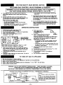
FOR YOUR SAFETY,
WILLIAMS
READ BEFORE
GAS CONTROL
LIGHTING
VALVE P295100A
& P295101A
I WARNING:
If youcausing
do not property
follow these
instructions
a fire
may result
damage,
personal exactly,
injury or
lossorofexplosion
life.
A.
This appliance has a pilot which must be lighted by
hand. When lighting the pilot, follow these Instructions
exactly.
B.
BEFORE LIGHTING
smell around the appliance area
for gas. Be sure to smell next to the floor because some
gas is heavier than air and will settle on the floor.
•
WHAT TO DO IF YOU SMELL GAS
• Do not try to light any appliance.
• Do not touch any electric switch; do not use any
phone In your building.
• Immediately
call your gas supplier from a neighbor's
phone. Follow the gas supplier's
instructions.
OPERATING
1.
2.
3.
4.
STOPI Read the safety information
above.
Turn off all electric power to the appliance
Open control access panel.
Push in gas control knob slightly and turn
clockwise F'_
to "OFF."
7.
call the fire
B.
Do not use this appliance
If any part has been under
water. Immediately
call a qualified service fechnlclan
to
inspect the appliance and to replace any part of the
control system and any gas control which has been
under water.
INSTRUCTIONS
8.
9.
DIAL
Turn knob on gas control
counterclockwise
to "PILOT."
Push in control knob all the
way and hold in. Immediately
light the pilot.
_1_
THERMOCOUPLE
• If knob does not pop up when released,
immediately
call your service technician
supplier.
NOTE: Knob cannot be turned from "PILOT" to "OFF"
unless knob is pushed in slightly. Do not force.
lo.
Wait five (5) minutes to clear out any gas then smell for
gas, including near the floor. If you then smell gas, stopl
Follow "B" in the safety information
above. If you don't
smell gas, go to next step.
Loosen wingnut and open the pilot observation
door (if
equipped).
Find pilot--follow
metal tube from gas control. The pilot is
mounted on side of burner,
11.
TO TURN
PILOT
BURNER
Continue to hold the control knob in for about one (I)
minute after the pilot is lit. Release knob and It wnl
pop back up. Pilot should remain lit. If it goes out,
repeat steps 5 through 10.
•
6.
your gas supplier,
Use only your hand to push In or turn the gas control
knob. Never use tools. If the knob will not push In or
turn by hand, don't try to repair It, call e qua,fled
sentice technician.
Force or attempted
repair may result In a
fire or explosion.
KNOB SHOWN
IN "OFF"
POSITION
5.
reach
C.
(if applicable).
TEMPERATURE
If you cannot
department.
12.
13.
stop and
or gas
If the pilot will not stay lit after several tries, turn
the gas control knob to "OFF"
and call your service
technician or gas supplier.
Close pilot observation
(if equipped).
door, tighten wJngnut
Turn gas control know counterclockwise
I_
to "ON".
Burner is now under control of the thermostatic
sensing element.
Turn temperature
counterclockwtae_toward
temperature.
Close control access door
Turn on all electric
(if applicable)
power
dial (numbered
1 thru 8)
8 to obtain desired
to the appliance
OFF GAS TO APPLIANCE
1. Turn off all electric power to the appliance if service is to be performed (if applicable),
2. Open control access panel,
3.
4.
Push in gas control knob slightly and turn
clockwise f_, to "OFF." Do not force.
Close control access panel.
WARNING:
DUE TO HIGH SURFACE TEMPERATURES -- KEEP CHILDREN, CLOTHING,
FURNITURE OR ANY COMBUSTIBLE MATERIAL AWAY FROM FURNACE.
IMPORTANT: KEEP BURNER AND CONTROL COMPARTMENT CLEAN, SEE PAGE 24.
CONNECTION
VENT
SHUT
OFF
SAFETY
_
DE'VICE
II
WIRING
DIAGRAM
FOR
BUILT-IN
THERMOSTAT
MODELS
LEGEND
'I'HERMOCOUPLE
I
GAS VALVE
BLACK
RE),IOTE
--20--
BULB
-FACTORY WIRED LOW VOLTAGE
NOTE:
IF ANY OF THE ORIGINAL WIRE AS SUPPLIED WITH THE APPLIANCE HAS TO BE
REPLACED, USE ONLY 18 GA., 4/64 INSULATION, 105e C. AWM COPPER WIRE OR
ITS EQUIVALENT
Operating
MODELS
2509621;
2509622;
SAFETY, OPERATING
3509621;
3509622;
Your Furnace
5009621
5009622
AND SHUTDOWN
All models listed above are equipped with a Williams
gas control valve part number P172100A; P172200A (see
page 22) or part number P295000A; P295001A (see
page 23).
The furnace operates like this:
1. Thermostat turns on the main burner.
2. Heat builds up in the furnace and starts the fan (if
equipped). The heated air comes out the front panel
louvers.
3. When the thermostat setting is reached, it shuts off the
main burner.
WARNING
I
(Con't)
4. The fan runs until the heat is removed from furnace,
then it turns off.
FLAMMABLE LIQUIDS OR VAPORS NEAR THE
DO NOT STORE OR USE GASOLINE OR OTHER
FURNACE.
NOTE
On new installation the gas lines will be filled with air and
may take several minutes to establish the pilot flame.
WARNING
DANGER OF PROPERTY DAMAGE,
BODILY INJURY OR DEATH
--MANUAL
IF THE FURNACE OVERHEATS OR FAILS TO
SHUT OFF, CLOSE MANUAL GAS VALVE FOR THE
FURNACE BEFORE TURNING OFF ELECTRIC
POWER FOR THE FAN.
USAGE:-
If furnace is equipped with a manual spark ignitor,
follow these next steps:
Your furnace is equipped with a 100% safety pilot which
will shut off the gas supply in case the pilot is not burning
or functioning properly. Make sure the pilot is adjusted
properly and that the pilot generator connection at the control valve is tight. If furnace will not stay lit, call your local
gas utility or gas supplier.
--MODEL
SPARK IGNITER
NUMBER
1. Review the operating instructions on preceding
pages.
2. When instructed to "light the pilot" depress red
button located on the burner pan for pilot ignition.
If necessary, depress red button several times for
pilot ignition.
3. If pilot fails to ignite or a spark is not present while
actuating red button, repeat steps 5 through 10
listed in operating instructions.
INFORMATION--
NOTE: CANADIAN MODEL NUMBERS THIRD
DIGIT FROM LEFT TO BE:
1 FOR BASIC ALTITUDES
2 FOR HIGH ALTITUDES
EXAMPLE:
MODEL: 3509612 BECOMES 3519612
(0-2000 FT. BASIC ALTITUDE)
OR BECOMES 3529612
(2000-4000 FT. HIGH ALTITUDE)
D21--
FOR YOUR SAFETY,
WILLIAMS
READ BEFORE
GAS CONTROL
LIGHTING
VALVE P172100A & P172200A
WARNING: If you do not follow these instructions exactly, a fire or explosion
may result causing property damage, personal Injury or loss of life.
A.
This appliance
has a pilot which must be lighted by
hand. When lighting the pilot, follow these Instructions
exactly.
B.
BEFORE LIGHTING
smell around the appliance
area
for gas. Be sure to smell next to the floor because some
gas Is heevler than air and will settle on the floor.
•
WHAT TO DO IF YOU SMELL GAS
• Do not try to light any appliance.
• Do not touch any electric switch; do not use any
phone in your building.
• Immediately
call your gas supplier from s neighbor's
phone. Follow the gas suppller's
Instructions.
OPERATING
1.
2.
3,
4.
5,
STOP! Read the safety information
above.
Turn off all electric power to the appliance
Set the thermostat to lowest setting.
Open control access panel.
Push in gas control knob slightly and turn
clockwise _
to "OFF."
_'
@!
If you cannot
department.
reach
your
gas supplier,
call the fire
C.
Use only your hand to push In or turn the gas control
knob. Never use tools. If the knob will not push In or
turn by hand, don't try to repair it, call a qualified servIce technician.
Force or attempted
repair may result In a
fire or explosion.
D.
Do not use this appliance
If any part has been under
water. Immediately
call a qualified service technician
to
inspect the appUance and to replace any part of the
control system and any gas control which has been
under water.
INSTRUCTIONS
GENERATOR
(if applicable).
9.
10.
knob slightly
Push
in gas control
and turn
counterclockwise
_
to "PILOT."
....._
n
J__
PILOT
Push in control knob all the way and
hold in. Immediately
light the pilot.
• If knob does not pop up when released,
immediately
call your service
tachnlclan
supplier.
•
Knob
cannot
unless
knob
is pushed
6.
7.
8.
be turned
from
in slightly.
"PILOT"
to "OFF"
Do not force.
11.
Wait five (5) minutes to clear out any gas then smell for
gas, including near the floor. If you then smell gas, stop!
Follow "B"
in the safety information
above. If you don't
smell gas, go to next step.
Loosen wingnut and open the pilot observation door (if
equipped).
Frnd pilot--follow
metal tube from gas control. The pilot is
mounted on side of burner.
TO TURN
1.
2.
3.
4.
5.
BURNER
Continue to hold the control knob in for about one (1)
minute after the pilot is lit. Release knob and it will
pop back up. Pilot should remain lit. If it goes out,
repeat steps 5 through 10.
CONTROL
KNOB SHOWN
IN"OFF'POSiTION
NOTE:
I
12.
stop and
or gas
If the pilot will not stay lit after several tries, turn
the gas control knob to "OFF"
and call your service
technician or gas supplier.
Close pilot observation door, tighten wingnut
(it equipped).
Turn gas control knob counterclockwise_to
13.
14.
Close control access panel.
Turn on all electric power to the appliance
(if applicable).
15.
Set thermostat
to desired
"ON".
setting.
OFF GAS TO APPLIANCE
Set the thermostat to lowest setting.
Turn off all electric power to the appliance if service is to be performed.
Open control access panel.
From "ON" position, depress and turn gas control knob clockwise _
to "OFF"
Close control access panel.
position. Do not force.
WARNING:
DUE TO HIGH SURFACE TEMPERATURES -- KEEP CHILDREN, CLOTHING,
FURNITURE OR ANY COMBUSTIBLE MATERIAL AWAY FROM FURNACE.
IMPORTANT: KEEP BURNER AND CONTROL COMPARTMENT CLEAN, SEE PAGE 24.
CONNECT;ON
WIRING
DIAGRAM
FOR WALL
THERMOSTAT
MODELS
LEGEND
GENE,_ATOR
T:'_E'=
M ©STAT
-FACTORY WIRED LOW VOLTAGE
NOTE:
IF ANY OF THE ORIGINAL WIRE AS SUPPLIED WITH THE APPLIANCE HAS TO BE
REPLACED, USE ONLY 18 GA., 4/64 INSULATION, 105" C. AWM COPPER WIRE OR
ITS EQUIVALENT
_-_
OEVIC_
BLACK
/)LACK
_
3 L_,C:<
I
J
m22--
FOR YOUR SAFETY,
WILLIAMS
READ BEFORE
GAS CONTROL
LIGHTING
VALVE P295000A
& P295001A
I WARNING:
If youcausing
do not property
follow these
instructions
a fire
may result
damage,
personal exactly,
injury or
lossorofexplosion
life.
A.
This appliance
has a pilot which must be lighted by
hand. When lighting the pilot, follow these Instructions
exactly.
S.
BEFORE LIGHTING
smell around the appliance
area
for gas. Be sure to smell next to the floor because some
gas is heavier than sir and will settle onthe floor.
• If you cannot
department.
WHAT TO DO IF YOU SMELL GAS
• Do not try to light any appliance.
• Do not touch sny electric switch; do not usa any
phone in your building.
• Immediately
call your gas supplier from a neighbor's
phone. Follow the gas suppiler's instructions.
OPERATING
1.
2.
3.
4.
5.
STOPi Read the safety Information
above.
Set the thermostat
to lowest satting.
Turn off sU electric power to the appliance
Open control access panel.
Push in gas control knob slightly and turn
clockwise _
to "OFF."
reach your gas supplier,
call the fire
C.
Use only your hand to push in or turn the gas control
knob. Never use tools. If the knob will not push In or
turn by hand, don't try to repair it, call a qualified service technician.
Force or attempted
repair may result In s
fire or explosion.
D.
Do not use this appliance
if any part has been under
water. Immediately
call a qualified service technician to
Inspect the appliance and to replace any part of the
control system and any gas control which has been
under water.
INSTRUCTIONS
9.
(if applicable).
10.
GAS CONTROL
KNOB SHOWN
IN "OFF" POSITION
Push in gas control
knob slightly and turn
counterclOCkwise
to "PILOT."
GENERATOR
_
PILOT
Push in control knob all the way and
BURNER
hold in. Immediately
light the pilot.
Continue to hold the control knob in for about one (1)
minute after the pilot is lit. Release knob and it will
pop back up. Pilot should remain lit. If it goes out,
repeat steps 5 through 10.
• if knob does not pop up when released,
immediately
call your sa_ice
technician
supplier.
•
NOTE:
unless
6.
7.
8.
Knob
knob
cannot be turned from "PILOT"
to "OFF"
is pushed
in slightly,
Do not force.
TO TURN
1.
2.
3.
4.
5.
11.
Wait five (5) minutes to clear out any gas then smell for
gas, including near the floor, if you then smell gas, stop!
Follow "B" in the safety information
above. If you don't
smell gas, go to next step.
Loosen wlngnut and open the pilot observation door (if
equipped).
Fiend pilot--follow
metal tube from gas control. The pilot is
mounted on side of burner.
stop and
or gas
If the pilot will not stay lit after several tries, turn
the gas control knob to "OFF"
and call your service
technician
or gas supplier.
12.
Close pilot observation door, tighten wingnut
(if equipped).
Turn gas control knob counterclockwise
_
13.
Close control
14.
Turn on sli electric
(if applicable).
15.
Set thermostat
access
to "ON".
panel.
power
to desired
to the appliance
setting.
OFF GAS TO APPLIANCE
Set the thermostat to lowest setting.
Turn off all electric power to the appliance if service is to be performed.
Open control access panel.
Push in gas control knob slightly and turn clockwise _
to "OFF". Do not force.
Close control access panel.
WARNING:
DUE TO HIGH SURFACE TEMPERATURES -- KEEP CHILDREN, CLOTHING,
FURNITURE OR ANY COMBUSTIBLE MATERIAL AWAY FROM FURNACE.
IMPORTANT: KEEP BURNER AND CONTROL COMPARTMENT CLEAN, SEE PAGE 24.
CONNECTION
WIRING
DIAGRAM
FOR WALL
THERMOSTAT
MODELS
LEGEND
VENT
SHUT
SAFETTHE_._
OFF
DEVICEI_
TAT
-I
r-]
I
GENERATOR
I
r-----1
GAS
VALVE
i
BLACK
--23--
-FACTORY WIRED LOW VOLTAGE
NOTE:
IF ANY OF THE ORIGINAL WIRE AS SUPPLIED WITH THE APPLIANCE HAS TO BE
REPLACED, USE ONLY 18 CA., 4/64 INSU LATION, 105° C. AWM COPPER WIRE OR
ITS EQUIVALENT
How To Care For Your Furnace
BURNER FLAME
WARNING
DANGER OF BODILY INJURY OR DEATH
Start the furnace and let it operate about 10 minutes
then look at the burner flame. Flames should be soft
and blue, see Fig. 23. If flames appear abnormal, contact
the gas company or a qualified service technician
immediately.
TURN OFF ELECTRIC POWER SUPPLY AT DISCONNECT SWITCH, FUSE BOX OR SERVICE
PANEL BEFORE REMOVING ANY DOORS OR ACCESS OR SERVICE PANELS FROM UNIT.
NOTE
CABINET FINISH
Clean cabinet with damp rag. Never use abrasive cleaners.
Cabinets are finished in heat resistant baked enamel -DO NOT refinish with wall paint.
No adjustment is provided, or is necessary, for models
equipped with welded formed steel burners.
MAIN BURNER FLAME PATTERN
FURNACE AREA
Keep the area near the furnace clear and free from combustible materials, gasoline, and other flammable liquids
and vapors.
COMBUSTION
Jl II It li
llBII
AND VENTILATION AIR
The combustion and ventilation air supply must not be
blocked.
Do not put anything in or on the furnace cabinet.
For better circulation and more effective heating, do not
place obstructive furniture closer than four feet to the front
of the cabinet or two feet to the side of the cabinet.
CORRECT
ANNUAL UPKEEP NEEDED
It is recommended that a qualified service technician
perform these checks at the beginning of each heating
season.
CLEANING
OPTIONAL FAN (If Equipped)
Shut off electricity, then remove screws and face panel.
Clean any lint or dirt from fan blades, fan motor, and exposed air passages. Use a brush. See page 33.
INNER
INSUFFICIENT
END CONES¸
AIR • LONG
OPEN
YELLOW IN COLOR
CONES
OUTER MANTLE
PROPER FLAME
lIGHT
BLUE POINTED
TOI
LIGHT BLUE
I/2 'r Io 3/4 ¸. H_GH
PILOT BURNER
Light pilot using instructions in OPERATING YOUR FURNACE on pages 18 through 23. Leave thermostat at lowest
setting.
Pilot flame should surround 1/2 to 5/8 inch of the generator
or thermocouple tip. Refer to Fig. 22, page 18. If flame
needs adjusting, do so as follows:
ADJUST PILOT BURNER
See Fig. 22, page 18 and Fig. 23.
1. Remove screw cover over pilot adjusting screw.
2. Insert small screwdriver. Adjust flame as needed. Turn
screw counterclockwise (=-'--,)to increase flame, clockwise (,--_) to decrease.
3. Turn thermostat to highest setting. Main burners should
light quickly and smoothly. Turn thermostat to lowest
setting. Main burners should go out. Pilot should
remain lit.
4. Replace screw cover with gasket over pilot adjusting
screw.
--24--
ADJUST MAIN BURNER FLAME PATTERN
Top vented wall furnaces equipped with cast iron burners
have an interrupter screw located under the burner body
and extends into the burner neck (venturi). This screw is
used to adjust the primary air to fuel mixture for proper
burner flame. Allow furnace to operate about 10 minutes
before making adjustments.
Burner flames should be a series of blue cones slightly
orange at the tips. When flames are sharp and blue with
no orange visible, turn air adjusting screw in burner venturi clockwise until very short orange tips are visible. If
flames are lazy and yellow, turn air screw counterclockwise
to eliminate yellow. See Fig. 23.
VENT SYSTEM
Make sure that no parts of the venting system are blocked
or rusted. Clean or replace before using furnace.
How To Care For Your Furnace
WARNING
I
(ton't)
in the burRer area will occur each heating season. It is
necessary to clean this area regularly. Use a vacuum
cleaner with a narrow attachment to reach small areas.
Be careful in and around the pilot. A change in its adjustment could be made if struck during cleaning.
MAKE SURE GAS SUPPLY IS OFF BEFORE
DANGER PANELS
OF BODILY
INJURY OR
DEATH
REMOVING
OR DOORS,
ETC.
BURNER CLEANING
FURNACE CONTROLS
Check burner. If cleaning is required, contact a qualified
service technician to clean and service burner.
INN_
TO REMOVE BURNER(S)
ELEMENT
Clean all foreign materials from top of burner. For access
to burner of all models:
THERMOCOUpIF
1. Open burner compartment door.
BOOY
RATING
PI..AT_
2. Shut off gas supply to furnace (Manual Shut-Off Valve).
3. Disconnect gas line inside cabinet at ground joint union
fitting. See Fig. 24.
I_MP.
4. Remove (2) screws securing burner pan assembly to
inner liner.
GAS
INPUT
GAS
MANUAL
FURNACE:
CAL'_ KNOB
SHUT-O_"
_OUN11NG
VALVE
LEG _
_'-DRIP LEG
REMOTE
"_IERMO BULB
GROUND
(ATTACHED UNDERSIDE OF VALVE)
JOINT UNION
RTIING
CLEANING
NOTE
If furnace is equipped with a welded formed steel
burner, remove additional (2) screws securing burner
to heating element.
5. Pull burner pan assembly forward approximately
1/2 inch and drop down to expose top of burner.
BURNER COMPARTMENT
Because cold air is attracted to the flame during furnace
operation, a build up of lint from bedding and dust (etc.)
Furnace
MODEL
NUMBER
2509612
2509622
2509611
2509621
3509612
3509622
3509611
3509621
5009612
5009622
5009611
5009621
Technical
6. After cleaning, replace burner pan assembly by reversing above procedure.
Information
TYPE
GAS
INPUT
RATING
BTU/HR**
HTG. CAPAC. MAIN BURNER ORIFICE
RATING
DRILL
DEC.
QTY.
BTU/HR**
NAT.
25,000
19,350
#43
.089
1
L.P.
25,000
19,350
#54
.055
1
NAT.
35,000
25,930
#38
.101
1
L.P.
35,000
25,930
#52
.063
1
NAT.
50,000
38,000
#43
.089
2
L.R
50,000
38,000
#54
.055
2
**For elevations above 2000 feet reduce ratings 4% for each 1000 feet above sea level.
***Btuh
= British Thermal Units per hour.
The efficiency rating of these appliances is a product thermal efficiency rating determined under continuous operating
conditions and was determined independently of any installed system.
--25--
TROUBLE SHOOTING
WILLIAMS
SYMPTOM
1. Pilot will not stay lit after
carefully following
lighting instructions.
GAS-FIRED
TOP
VENT
GRAVITY
POSSIBLE CAUSES
WALL
FURNACE
CORRECTIVE ACTION
A. Thermocouple or
generator producing insufficient millivoltage.
Check pilot flame - must impinge on thermocouple
or generator. Be sure thermocouple or generator is
fully inserted in bracket.
B. Loose or dirty thermocouple or generator connections at gas valve.
Clean and/or tighten thermocouple or generator connections at valve.
C. Thermocouple or
generator defective.
Check thermocouple with millivolt meter. Should
generate approximately 30 millivolts when not connected to load. When connected to load, should
generate approximately 14 millivolts; if below 7
millivolts, replace.
Check generator with millivolt meter. Take reading
at generator terminals of valve with pilot burning and
thermostat contacts closed. Should be 140 millivolts
or more.
2. Pilot burning - no gas to
main burner.
3. Furnace operates but
turns "Off" before room
temperature is attained.
D. Grounded thermostat
lead wire. (Wall thermo*
stat model.)
Remove thermostat lead wires from valve terminals.
If pilot now stays lit, trace thermostat wiring circuit
for a ground. May be grounded to furnace or gas
supply.
E. Thermomagnetic pilot
safety defective.
Replace gas valve after above is checked out.
F. Vent Safety Shutoff
System.
Check wiring connections from valve to vent safety
shutoff device. Be sure all connections are tight.
Check for blocked vent or disconnected vent.
A. Manual valve not turned
to "On" position after
lighting pilot.
Turn gas valve knob to "On" position.
B. Temperature dial or
thermostat not turned to
a position calling for heat.
Set temperature dial or thermostat to a position calling for heat.
C. Plugged burner orifice.
Check - clean or replace.
D. Temperature dial out of
calibration. (Bulb control
model.)
See valve instruction sheet.
E. Mis-wired or broken thermostat wires. Defective
thermostat. (Wall thermostat model.)
Check connections at valve terminals. If valve
operates check thermostat wires.
F. Pilot generator may not
be generating sufficient
millivoltage to open valve.
Sea 1A above.
G. Defective valve.
Replace.
A. Sensing bulb not located
properly. (Bulb control
model.)
Check location of sensing bulb - see Fig. 24, page
25.
B. Temperature dial out of
calibration. (Bulb control
model.)
See valve instruction sheet.
(Continued next page
--26--
TROUBLE SHOOTING
WILLIAMS
SYMPTOM
GAS-FIRED
TOP
VENT
POSSIBLE CAUSES
GRAVITY
WALL
FURNACE
CORRECTIVE
ACTION
3. Furnace operates but
turns "Off" before room
temperature is attained.
(continued)
C. Thermostat location.
(Wall thermostat model.)
Check thermostat location - should not be in the
path of warm air discharge from furnace, near a
lamp, or above a TM. or stereo set.
D. Defective thermostat.
(Wall thermostat model.)
Check thermostat calibration or replace.
4. Furnace not producing
sufficient heat.
A. Furnace may be too
small for space being
heated.
Check heat loss calculations.
B. Furnace not burning at
full rate.
Check for low gas pressure at gas valve - should
be 4" W.C. for natural gas; 11" W.C. for L.RG. Check
burner orifice.
A. Sensing bulb not located
properly. (Bulb control
model.)
Check location of sensing bulb - see Fig. 24, page
25.
B. Temperature dial out of
calibration. (Bulb control
model.)
See valve instruction sheet.
C. Bulb or capillary broken.
(Bulb control model.)
Replace valve.
D. Thermostat wiring defective. (Wall thermostat
model.)
Thermostat lead wires may be shorted together
caused by a nail or staple - check by removing thermostat leads from valve terminals.
E. Thermostat location.
(Wall thermostat model.)
Check thermostat location - if on an outside wall or
a hole in wall behind thermostat causing cold air to
contact thermostat - relocate.
F. Defective thermostat.
(Wall thermostat model.)
Check thermostat calibration or replace.
G. Dirt under valve seat or
valve stuck open.
Replace valve.
6. Pilot outage problem.
A. Pilot flame may be low or
blowing (high) causing
safety to drop out.
Adjust pilot flame. Pilot orifice or aerating hole may
be plugged (check for spider webs or other organic
material).
7. Abnormal operation.
A. Delayed ignition - pilot
flame may be too low.
Adjust pilot flame.
B. Expansion noise ticking.
Check installation - casing may be distorted by
being fastened to an uneven opening or jammed
under header.
C. Spillage
Check vent system - may be blocked flue, excessive
down draft (wind) or negative pressure in room caused by ventilating fan or a fire in a fireplace, Correct
as necessary.
D. Excessive flame roll-out.
Furnace possibly over rate - check for high gas
pressure at gas valve (see 4B above).
5. Furnace operates but will
not shut "Off" when
room temperature is
attained.
m27m
WILLIAMS
GAS-FIRED
TOP VENT GRAVITY WALL FURNACE
REPLACEMENT
PARTS
2509611;
2509612;
3509611;
3509612;
REF.
NO.
PART
LIST FOR
2509621;
3509621;
MODELS
2509622
3509622
-
DESCRIPTION
NO.
1
4915
FACE PANEL
2
9C155
FRONT HEAT SHIELD
3
9D52
COMBUSTION CHAMBER
ASSY.-
3
9D54
COMBUSTION CHAMBER
ASSY.
4
9B199
DEFLECTOR
5
9C153
INNER SHIELD TOP
6
9C166
DRAFTHOOD
ASSEMBLY-
2509611;
2509612;
2509621;
2509622
6
9C165
DRAFTHOOD ASSEMBLY-
3509611;
3509612;
3509621;
.:3509622
7
P321826
LIMIT SWITCH-
2509611;
2509612;
2509621;
2509622
7
P322055
LIMIT SWITCH -
,3509611;
3509612;
3509621;
.3509622
8
9C172-1
SHIELD ASSEMBLY
9
5902
HEADER ASSEMBLY
10
11
"A'A-
"_
6901
(REF.
P320994
DOOR HANDLE
P322085
OWNERS MANUAL
SHOWN
2509621;
2509622
3509612;
3509621;
.3509622
9B56-1)
"_ NOT AVAILABLE
SEPARATELY
SCREWS AND BOLTS ARE STANDARD
FOR PARTS
2509612;
3509611;
/
REAR PLASTERGROUND _--'---REAR
OVAL B//W VENT KIT
NOTE:
2509611;
REAR OUTLET
9901
,A-NOT
-
ILLUSTRA]3ONS,
OUTLET REGISTER
(KIT FORM ONLY)
HARDWARE
ITEMS, AVAILABLE
LOCALLY.
SEE BELOW AND PAGE 29
REAR OUTLET REGISTER
6901
m28--
WILLIAMS
GAS-FIRED
TOP VENT GRAVITY WALL FURNACE
REPLACEMENT
PARTS FOR
2509611;
2509612;
2509621;
3509611;
3509612;
3509621;
MODELS
2509622
3509622
I
I
USE ONLY MANUFACTURER'S
AUTHORIZED
PARTS
=,,_
ip,lo.,,e3
--29--
WILLIAMS
GAS-FIRED
TOP VENT GRAVITY WALL FURNACE
CONTROL ASSEMBLY
REPLACEMENT PARTS LIST FOR MODELS 2509611;
2509612;
2509621;
2509622
3509611;
3509612;
3509621;
3509622
_;_
REF.
NO.
PART
NO.
DESCRIPTION
00000000
_LO u3 LO
Cxl r,o
1
9Ct05
T-BURNER
1
P025600
BURNER
2
P043800
GENERATOR
3
P321837
PILOT BURNER
3
P179800
PILOT BURNER
3
P322274
PILOT
BURNER
3
P322275
PILOT
BURNER
4
9C104
BURNER
PAN
ASSEMBLY
(T-BURNER)
4
9B59
BURNER
PAN
ASSEMBLY
(CAST
5
P321828
TERMINAL
6
P322051
CONTROL
GAS
VALVE
6
P522052
CONTROL
GAS
VALVE
6
P172100A
CONTROL
GAS
VALVE
6
P172200A
CONTROL
GAS
VALVE
7
P328500
ORIFICE
ADAPTER
8
P090500
ORIFICE
(SPECIFY
9
P026200
LOCKNUT
10
9A106
MANIFOLD
RETAINER
11
12A01
MANIFOLD
ASSEMBLY
12
P321856
WIRE ASSEMBLY
13
P522016
THERMOSTAT
(FORMED
(CAST
STEEL,
NAT.
GAS ONLY)
X
X
IRON)
X
X
BLOCK
X
X
X
TYPE
(CAST
(CAST
& INPUT)
X
X
X
X
X
X
X
X
X
X
X
X
X
X
X
X
X
×
X
X
X
X
X
X
X
IRON BURNER)
IRON BURNER)
REQUIRED)
FOR PARTS ILLUSTRATIONS, SEE PAGE 31
X
X
X
X
X
X
X
X
X
X
X
X
X
X
X
X
X
' X
X
X
X
X
X
X
X
X
X
X
X
X
X
X
X
X
;X
X
X
X
"X" DENOTES USAGE
NOTE: SCREWS AND BOLTS ARE STANDARD HARDWARE ITEMS, AVAILABLE LOCALLY.
m30--
OJ
X
X
GAS
(2
:X
X
X
IRON)
THERMOCOUPLE
X
X
X
X
X
WILLIAMS
GAS-FIRED
TOP VENT GRAVITY
REPLACEMENT
2509611;
2509612:
2509621;
2509822;
3509811;
FOR REPLACEMENT PARTS LISTING
NAT. GAS
CONTROL ASSEMBLY
L.P.
CONTROL
I
I
I
I
I
I
I
PARTS FOR MODELS
GAS
ASSEMBLY
WALL FURNACE
--
3509612;
3509621;
SEE PAGE 50
3509622
WILLIAMS GAS -
FIRED TOP VENT GRAVITY WALL FURNACE
REPLACEMENT PARTS LIST FOR MODELS 5009611;
5009612;
5009621 ; 5009622
REF. PART
NO.
NO.
DESCRIPTION
1
4.915
FACE PANEL (2 REQUIRED)
2
9C155
FRONT HEAT SHIELD (2 REQUIRED)
3
9A277
CARRYOVER SHELL
4-
9D65
COMBUSTION
4A
9073
COMBUSTION CHAMBER ASSEMBLY (REAR)
5
9C171
OUTER CASING ASSEMBLY
6
95199
DEFLECTOR
7
5901
HEADER
8
P321826
UMIT SWITCH
CHAMBER ASSE]_BLY (FRONT)
(REF. - 9C30)
9
9C'170
DRAF-IHOOD ASSEMBLY (2 REQUIRED)
I0
9C157
NON -
11
9C158
INNER SHIELD TOP (2 REQUIRED)
9901
OVAL B/W VENT KIT
DOOR HANDLE
P320994
P322085
,#
VISION SHIELD
OWNERS MANUAL (REV. 11/95)
NOT SHOWN _" NOT AVAILABLE SEPARAltl.Y
(KIT FORM ONLY)
NOTE: SORES',/SAND BOLTS ARE STANDARD HARDWARE I'[_MS, AVAILABLE LOCALLY.
FOR PARTS ILLUS'i'RATIONS SEE PAGE 33
--32--
WILLIAMSGAS -
FIRED TOP VENT GRAVITY WALL
FURNACE
REPLACEMENT PARTS FOR MODELS
5009611;
5009612;
5009621;
500962?
\
\\
©
USE ONLY MANUFACTURER'S
AUTHORIZED PARTS
,_,_._
IF.t{w-€}
--33--
WILLIAMS
GAS-FIRED
TOP VENT GRAVITY
WALL FURNACE
CONTROL ASSEMBLY
REPLACEMENT PARTS LIST FOR MODELS 5009611;
5009612;
5009621;
5009622
LO
REF.
NO.
PART
NO.
DESCRIPTION
ooo
O
9C105
T-BURNER (FORMED STEEL.NAT. GAS ONLY),2 REQUIRED.
1
P025600
BURNER
2
P043800
GENERATOR
3
P320758
CARRYOVER
PILOT
-
NAT.
3
P320778
CARRYOVER
PILOT
-
L.P.G.
3
P322396
CARRYOVER
PILOT
-
NAT.
3
P322397
CARRYOVER
PILOT
-
L.P.G.
4
9C95
BURNER
PAN
ASSEMBLY
(T-BURNER)
4-
9C34
BURNER
PAN
ASSEMBLY
(CAST IRON)
5
P321828
TERMINAL
BLOCK
6
P322052
CONTROL
GAS
VALVE
6
P322051
CONTROL
GAS
VALVE
6
P1722OOA
CONTROL
GAS
VALVE
6
P17210OA
CONTROL
GAS
VALVE
7
9A174
SHIELD-BRNR.
8
P090500
ORIFICE
9
(CAST
IRON),
2
REQUIRED.
(2
X
X
(FORMED
REQ. SPECIFY
STL.
GAS
9A108
MANIFOLD
ASSEMBLY
(CAST
9A200
MANIFOLD
ASSEMBLY
(FORMED
12
7A189
PIEZO
13
9B124
CARRYOVER
BRACKET
(CAST
1,3
9C96
CARRYOVER
BRACKET
(FORMED
14
P322016
THERMOSTAT
P321836
WIRE ASSEMBLY
BRNR.,
NAT.
GAS
ONLY).
TYPE & INPUT)
2 REQUIRED.
SPARK
BRACKET
IGNITOR
(SPARK
(2
SEE PAGE
ARE
X
X
X
11
BOLTS
X
X
11
AND
X
X
X
MANUAL
SCREWS
X
ll4ERMOCOUPLE
PAN
X
X
LOCKNUT,
NOTE:
X
X
X
9A298
ILLUSTRATIONS,
x
x
X
P026200
PARTS
o
O
x
10
FOR
tO
u-)u-)u3 u-)
1
15
_O!LO
(PIEZO)
IRON
BURNER)
STEEL
X
X
X
X
X
X
X
X
X
X
BRNR.
NAT
GAS ONLY)
"X"
HARDWARE
ITEMS,
X
X
DENOTES
AVAILABLE
X
X
USAGE
LOCALLY
X
X
X
X
35
X
X
IRON BURNER)
m34--
X
X
IGNITOR)
STL.
X
X
BURNER)
REQUIRED)
STANDARD
X
X
×
X
X
X
X
X
WILLIAMS
GAS-FIRED
TOP VENT GRAVITY
REPLACEMENT
5009611;
PARTS FOR
5009612:
5009621;
MODELS
WALL FURNACE
-
5009622
FOR PARTS LISTING, SEE PAGE 54
NAT. GAS
CONTROL ASSEMBLY
I
L.P. GAS
CONTROL ASSEMBLY
USE ONLY MANUI:'ACTURER*S
AUTHORIZED
PART5
135--
LIr/oo-ol
INSTALLATION
INSTRUCTIONS
2901 BLOWER ACCESSORY
KIT
NOTE: All electrical work must conform to your local
codes and ordinances or in their absence, with currant National Electrical Code, ANSI/NFPA 70. If
you are not familiar with wiring codes in general, have
a competent electrician do this job.
STEP 8.
Drill 1/8 inch diameter hole in each side of
the furnace face panel through the holes on
the sides of the fan cabinet, and secure the
cabinet to the furnace with the two sheet
metal screws provided.
NOTE: Set blower cabinet against _all surface (required on deeper face
panels).
WARNING.
DANGER OF PROPERTY DAMAGE,
BODILY INJURY OR DEATH
TURN OFF ELECTRIC POWER SUPPLY AT DISCONNECT SWITCH, FUSE BOX OR SERVICE
PANEL BEFORE REMOVING OR WORKING ON
FAN CABINET.
STEP 9.
Replace junction box cover, securing with
screws previously removed.
STEP 10. Replace blower grille, securing with screws
previously removed.
BLOWER ACCESSORY KIT
This accessory is installed on furnace top and increases circulation of warm air through heated space.
A 115V outlet adjacent to the furnace is required.
For Automatic SettingYou must select "HI" or "LOW" position. When
furnace heats up the temperature sensing device will
be activated and the fan will operate.
STEP 11. Set switch to desired position. If left in "HI"
or "LOW" position during summer months
blower accessory could be activated by
sunlight striking furnace face panel through
unshaded windows. If this is undesirable
set switch to "OFF" position.
FIG. A
Blower accessory will not operate if toggle switch is
set in off (center) position.
Install as follows:
STEP 1. Install 115V electrical outlet where shown
in your owners manual; see rough-in
illustration
STEP 2. Remove (2) screws securing blower grille
assembly, and remove blower grille
(See Fig. A.)
STEP 3. Remove (2) screws securing junction box
cover (See Fig. C). Then remove cover to
gain access to knockout hole located in
junction box (See Fig. C)
OP_ONAL
STEP 4. Locate knockout hole and remove knockout
using a hammer and screwdriver.
STEP 5. Place blower cabinet on furnace top
(See Fig. A).
STEP 6. Route 115V field wiring into junction box
through knockout hole.
STEP
Make field wiring connection inside junction
box (See Fig. B). Follow applicable local
and national electrical codes.
--36--
FAN
ACCESSORY
SEE PAGE 37 FOR ADDITIONAL
ILLUSTRATIONS
INSTALLATION
REF. ;'ART NO.
NO.
1
P013200
2
INSTRUCTIONS
DESCRIPTION
FIG. B.
BLOWER ACCESSORY KIT NO. 2901
Screw-#8x3/8SheetMetal(8) Required
FAN
5"t_TCH
BlowerGrille
3
P093200
4
P1410C0 Screw-#10xl/2SheetMetal(1)Required
NOT
Screw-#Bx3/8
SheetMetal(2)Required
I_
BK
5
P320911A FanSwitch-2 Speed
6
P3,?.G912 WireBridle
7
P127300
Washer-flat#10-32(2) Required
8
P04110
NutMach.-#8-32WlStarWasher(2) Required
9
9C102
BlowerBody
10
P321078
Grommet-motor
mount(2) Required
11
P012900
Bushing-Strain
Relief
O
12
P322395
Automatic
FanSwitch
[_1/4
13
P029200
Borew-Machine
- #6-32x15/16
(2) Required
NOTES:
14
P320905
Motor-2 Speed
15
P320907
FanBiede
16
9D12-1
OrificePlate
17
68161
Junction
BoxPlate
51.
I
"
I HOT
I
F_I
_TCH
----
--
HI_
1r5v
6_,4z
I
I GNO
TCGG-E
S_T_:H
_-
vo_toge
eL
LEGEND
_d,
-
factory _g
_k_< co_ect t,=,-mln_=
for
focto,"y wk-th<j con_ect_nL
ELK- BLACX BL "
1
W
"q" t
NEUT I
I
Hl<jt_ "*_dto_e roctoPf.
connector for" ltho _to_
w_
FAN
},ITR
BLUE W = Y_'_ITE
R - R_
Motor is therr_ly
G-
prolected
2 If any o_ the origiP_d wire as supple3 with the ap_iarme has
to be replaced, u,_ c_ty 18 Ga, 4/64 ir_Jiabon, 105o C. AWM cop >er wire or ds equivalent
HSV
6OHz. - less than 3 _ps.
FROt*4 SUPPLY C_RC_IT, BE;"OR£ S_VtC_
WA.R.NING: OlS_C_NNECT APPLIANC_
[OR CLEANING,
Tot_
6
_
load
I_
than
3 AMPS* |
P320904
_
JUNC_ON
3
1
9
\,
12
14
15
FIG. C
--37--
]
Service
DATE
MAINTENANCE
Record
PERFORMED
COMPONENTS
--38 D
REQUIRED
--
Notes
--39--
--
Service Hints
If your furnace fails to work right, you may avoid inconvenience and the cost
of a service call by checking the following points before you call for service.
FOR YOUR SAFETY
FOR YOUR SAFETY
Do not store or use gasoline
or other flammable vapors and
liquids in the vicinity of this or any
other appliance.
POSSIBLE CAUSE
.0TE
:"
DIGIT FROM
DIAN_ MODEL NUMBERS
LEFT ,T_ BE:
1_FOR8ASIC_LTRUDES
2_EORHIGH,ALTITUDES
EXAMPLE_ ' ._."
MODEL;
_-
.
3519612
(0-2000FT. BASICAL1TrUOE)
350961_BECOMES
OR BECOMES
:
THIRD
if blower motor is noisy -Housing rattling.
Blower dirty.
Blower wheel bent.
Tighten screws.
Clean blower wheel.
Straighten or replace.
3529612
See troubleshooting section for more detailed information.
How to Order
1.
2.
3.
4.
WHAT TO DO
If your furnace Is not heating or not giving enough heat -Thermostat is not set correctly.
Reset thermostat to desired setting.
Pilot is out.
Check pilot. Relight if necessary
following instructions for "Operating
Your Furnace:'
Pilot is on but burner won't
If gas valve is set at other than "On"
come on,
furnace will not operate. Shut furnace
down and follow instructions for
relighting in "Operating Your Furnace" section.
Burner is not operating
Check flame, If it is yellow the burner
properly.
is not getting enough air. Or if flame
is blue and noisy and seems to lift off
the burner, the burner is getting too
much air. See "Checks and Adjustments:' page 24,
Air flow restricted.
Check that doors, drapes or furniture
are not blocking furnace louvers.
Pilot goes out time after time -Furnace flue blocked.
Locate vent outlet blockage and
clean.
Pilot and burner access door
Check the door. See section on
not closed properly.
"Operating Your Furnace" beginning
on page 18.
If burner is noisy -Gas input amount is incorrect.
Contact Williams Service Department.
Too much primary air.
Contact Williams Service Department.
If blower does not run -Fan switch not set.
Select fan speed.
Blower not connected to
Connect to electric power.
electric power.
(2000-4000FT. HIGHALTITUDE)
When ordering
information:
If you smell gas:
1. Open windows.
2. Don't touch electrical.
3. Extinguish any open flame.
4. Immediately call your gas
supplier.
repair
parts,
always
MODEL NUMBER
MFG. DATE CODE
PART NUMBER
PART DESCRIPTION
© 1997 The Williams Furnace Company
give the following
Repair
Parts
All parts listed herein may be ordered from your equipment supplier.
The Model Number of your Williams wall furnace will be
found on the rating plate near gaB valve, inside control
compartment.
WILLIAMS
FURNACE COMPANY
225 Acacia Street
Colton, CA 92324 USA
MANUFACTURED
IN THE U.S.A.
Established 1916
(909) 825-0993
FAX: (909) 824-8009
Printed in U.S.A.
REV. 5/97
P322085