1
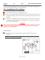
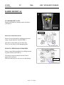
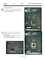
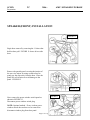
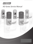
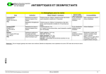
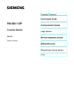
Document # 3667
SCION
TC
Posted 10/13/05
AMP / SPEAKER UPGRADE
2006 -
Preparation
Part Number: 00016-79420
Code: YA6
Kit Contents
Item #
1
2
3
4
5
6
General Applicability
Quantity Reqd. Description
1
AMPLIFIER
1 PAIR
FRONT SPEAKERS
1 PAIR
REAR SPEAKERS
1
MAIN HARNESS
1
AUX HARNESS
1
CAPACITOR
SCION TC ALL GRADES
Recommended Sequence of Application
Item #
1
2
3
4
5
Hardware Bag Contents
Item #
1
2
3
Quantity Reqd.
10
4
16
Description
4 INCH WIRE TIES
FOAM TAPE
RIVETS
Accessory
INSTALL SECURITY
SATTELITE RADIO INSTALL
AUDIO UPGRADE INSTALL
INSTALL DOOR SILLS
INSTALL MOLDED DASH
Vehicle Service Parts (may be required for reassembly)
Additional Items Required For Installation
Item #
1
2
3
Quantity Reqd.
Description
Item #
1
2
3
Quantity Reqd. Description
*Mandatory
Conflicts
Recommended Tools
Personal & Vehicle
Protection
Legend
Notes
VEHICLE PROTECTION
PART PROTECTION
SEAT/FLOOR COVERS
BLANKETS
Special Tools
Installation Tools
Notes
GREASE PENCIL
REMOVAL TOOL
SOCKET / WRENCH
UTILITY KNIFE
SOCKET / RATCHET
TORQUE WRENCH
Notes
PLIERS
SCREWDRIVER
DRILL
NYLON TOOL
10 MM
TO SLICE CARPET
12 MM, 14 MM
30 ft. lbs
36 in lbs. & 9 ft. lbs.
6” (Optional)
DIAGONAL AND LONG
3/16” DRILL BIT
Special Chemicals
Notes
SEALANT
3M SEALANT
SPECIAL NOTE: Installation Sequences
After TMS and Safety mandated preparatory steps have been
taken, the installation sequence is the suggested method for
completing the accessory installation. In some instances the
suggested sequence is written for one associate to install and in
others the sequence is given as part of a team accessory
installation. Unless otherwise stated in the document, the
associates may perform the installation steps in any order to
make the installation as efficient as possible while maintaining
consistent quality.
Also some items listed to be removed may not need to be
removed if caution is taken to not damage vehicle.
Page 1 of 11 pages
SCION
TC
2006 -
AMP / SPEAKER UPGRADE
Preparation
Care must be taken when installing this accessory to ensure damage does not occur to the vehicle. The installation of this
accessory should follow approved guidelines to ensure a quality installation.
Pre-installation Precautions
STOP
(a) Use Seat and Floor Protectors to avoid damage to surfaces.
(b) If the vehicle is equipped with an Anti-Theft Radio, the radio code must be written down prior to
disconnecting the battery cable. The code must be reentered when the negative battery cable is
reinstalled.
(c) If the vehicle is equipped Airbags, precautions must be taken to ensure that sensors and bags are
not damaged or altered during the course of the installation. Check vehicle repair manual for
proper precaution implementation.
CAUTION:
When servicing an SRS system (airbag) or working on an item related to this system, a
minimum of 90 seconds waiting time must be met after removing battery negative
terminal ( ref. TSB:EL93-00 1).
Battery Disconnect
(c) Using a 10mm Socket or wrench, disconnect the battery NEGATIVE cable as shown
(FIGURE 1)
MAKE SURE YOU HAVE WRITTEN DOWN OR DEACTIVATED THE BUILT IN RADIO
SECURITY CODE BEFORE PROCEEDING.
.
Figure 1
Page 2 of 11 pages
SCION
TC
2006 -
AMP / SPEAKER UPGRADE
Preparation
RADIO REMOVAL
STANDARD SHIFT ONLY
Remove shift knob by rotating counter clockwise
(FIGURE 2)
FIGURE 2
FIGURE 3
REMOVE LOWER TRIM PANEL
Remove lower trim panel by pulling upwards and
using a Nylon Removal Tool (FIGURE 3)
Disconnect wiring from power source plug.
Place in a safe area to avoid damaging panel.
REMOVE UPPER RADIO TRIM BEZEL
Remove upper Radio trim Bezel by pulling outward
on panel as shown (FIGURE 4)
Disconnect electrical connector on the back of
upper radio trim bezel.
Place the trim bezel in a safe area to avoid damage.
.
Page 3 of 11 pages
FIGURE 4
SCION
TC
2006 -
AMP / SPEAKER UPGRADE
Preparation
REMOVE THE HEAD UNIT (FIGURE 5)
Remove the two (2) nuts on top and the two (2)
screws on the bottom. (FIGURE 5)
FIGURE 5
Pull head unit straight out.
Disconnect the connectors.
REMOVE DRIVERS SEAT
Remove 4 bolts at seat mount.
Disconnect seat plug and remove seat.
MAIN HARNESS / AMPLIFIER INSTALLATION
HARNESS ROUTING
Route main harness down from radio cavity to
transmission hump. Make sure that when routing
harness, care and wire ties are used to keep the
harness free of the shifting mechanism. FIGURE 6
NOTE: This can be accomplished by pulling the
carpet down and following factory harness.
FIGURE 6
Continue to run harness along transmission hump as
shown in FIGURE 7. Use wire ties to keep harness
free of emergency brake mechanism.
Connect ground wire and torque to 9 ft.lbs.
FIGURE 7
Page 4 of 11 pages
SCION
TC
2006 -
AMP / SPEAKER UPGRADE
Preparation
AMPLIFIER LOCATION
Cut a 1” slit 4 ½ “back from front seat brace and 4
¼” from the transmission hump going towards the
outboard side. (FIGURE 8)
4 ¼”
4 ½”
FIGURE 8
Amplifier will be located 1” back from the front
seat brace and 7” from the transmission hump
(FIGURE 9 & 10)
Using amplifier as a template and a grease pencil
mark hole locations on carpet..
Cut carpet at marked holes and mount amplifier.
FIGURE 10
Page 5 of 11 pages
FIGURE 9
SCION
TC
2006 -
AMP / SPEAKER UPGRADE
Preparation
SPEAKER (FRONT) INSTALLATION
FIGURE 11
Begin door removal by removing the 11 claws that
hold on door pull. FIGURE 11 shows drivers side
door.
Remove the garnish panel covering the interior of
the rear view mirror by using a removal tool to
gently pry the clips away from the door. Place the
panel in a safe location to avoid damage to the
panel. FIGURE 12
FIGURE 12
Next, remove the power window switch panel as
shown in FIGURE 13.
Disconnect power window switch plug.
NOTE: Optional method - If care is taken power
window switch does not have to be removed to
disconnect window plug from door panel.
Page 6 of 11 pages
FIGURE 13
SCION
TC
2006 -
AMP / SPEAKER UPGRADE
Preparation
Remove the remaining screws (3) in the door panel,
and pull the panel gently to remove the clips.
FIGURE 14
FIGURE 14
The entire panel can then be removed by pulling the
remaining clips. Place panel in a safe place to avoid
damage to the panel. (FIGURE 15)
Using a drill with a 3/16” bit, carefully drill out the
rivets holding the original speaker in place. Be sure
to use a vacuum cleaner to remove the metal
shavings from the inside of the door. (FIGURE 16)
Unplug the original speaker, and remove the plastic
housing.
FIGURE 15
FIGURE 16
IMPORTANT NOTE: 3M Sealant must
be used in speaker holes before installing
new rivets.
Page 7 of 11 pages
Document # 2541
SCION
TC
2006 -
Created 7/5/04
AMP / SPEAKER UPGRADE
Preparation
FIGURE 17
Rivet in replacement speakers as shown in
FIGURE 17. Take special care when riveting in
new speakers to follow the correct rivet
installation procedures detailed in FIGURE 18.
Plug the connector removed from the original
speaker into the new housing.
PASSENGER SIDE DOOR SPEAKER
INSTALLATION IS THE SAME AS
DRIVERS SIDE
FIGURE 18
.
Page 8 of 11 pages
SCION
TC
2006 -
AMP / SPEAKER UPGRADE
Preparation
SPEAKER (REAR) INSTALLATION
REMOVE PASSENGER SIDE DOORSILL (FIGURE 19)
FIGURE 19
NOTE: If a clip remains on the vehicle, remove
it and replace it back into the plastic doorsill cover.
REMOVE THE REAR SEAT CUSHION (FIGURE 20)
Pull upward on the front of the seat cushion to release,
and then slide the seat cushion forward and upward.
NOTE: Be careful not to damage the seat, door
and other vehicle parts when removing the seat
cushion from the vehicle.
LOOSEN THE REAR PASSENGER SIDE TRIM PANEL
(FIGURE 21 & 22)
Remove the plastic hook to remove the
rear passenger side trim (FIGURE 22)
FIGURE 20
FIGURE 21
Push on the button with a nylon removal
tool and twist hook counter-clockwise by
90 deg.. (FIGURE 22)
Pull hook straight out while pushing
button. (FIGURE 22)
Remove the two (2) plastic clips on the
floor. (FIGURE 21)
FIGURE 22
Partially remove the weather-strip
molding trim.(FIGURE 21)
Partially pry away the side trim panel to release the 8 clips
and 3 claws (along upper edge). (Figure 21).
Page 9 of 11 pages
SCION
TC
2006 -
AMP / SPEAKER UPGRADE
Preparation
Remove Rear Speaker by removing (3) 10mm bolts.
Disconnect Speaker wiring plug. (FIGURE 23)
Replace speaker using the same bolts removed
above. Reconnect Speaker wiring plug.
Re-assemble all removed parts in reverse order
as removed.
Re-install Drivers seat and torque to 30 ft.lbs.
FIGURE 23
DRIVERS SIDE INSTALLA TION IS THE
SAME AS PASSENGERS SIDE
CAPACITOR INSTALLATION (FIGURE 24)
TO MIRROR SWITCH CONNECTOR
Using a nylon tool pop out the mirror switch plate.
Attach one T-tap to the blue wire at pin 8
Attach one T-tap to the brown/yellow wire at pin 7
Connect the red lead to the blue wire pin 8
FIGURE 24
Connect the black lead to the brown/yellow wire pin 7
Re-install mirror switch plate.
Reconnect the NEGATIVE battery cable as shown
in FIGURE 25. The cable must be connected at 45
degrees, and torque to 36 lbf-in.
Proceed to Functional Verifications (page 11)
Clean up and remove any trash.
FIGURE 25
Page 10 of 11 pages
SCION
TC
2006 -
AMP / SPEAKER UPGRADE
Preparation
FUNCTIONAL VERIFICATIONS
Check:
Look for:
ACCESSORY VERIFICATIONS
Verify proper operation of the Tuner. If no radio station can
be received, check to ensure antenna was plugged into radio
Radio tuner
Subwoofer should operate. If not, check connection of AUX
harness at amplifier.
Bazooka Subwoofer (if installed)
VEHICLE FUNCTION CHECKS
Ensure proper operation of the hazard switch.
Hazard Switch
Passenger’s and Drivers seat belt reminder light
Proper operation of the passenger and drivers seat belt
reminder light.
Ensure that removed seat is securely fastened.
Driver’s side front seat
Proper operation of the removed seat lock mechanism
Ensure proper operation of the removed seat lock mechanism.
SRS warning light
SRS warning light illuminates for approximately 6 seconds
when the ignition is turned ON, then goes out.
HVAC
Proper operation of the Air Conditioning system.
Page 11 of 11 pages