1
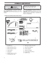
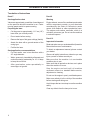
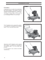
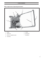
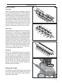
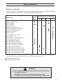
Operators Manual
Models:
PR18B5FA
PR18B5NRA
PR18GH5NRA
PR18H5DA
PR18H5FA
PR18H5NRA
PR18NEFA
PR22B5FA
PR22B5NRA
PR22B8FA
MANUAL NO. 107176 REV. 03 (12/02/02)
PR22B8NRA
PR22GH5NRA
PR22H5FA
PR22H5NRA
PR22NEFA
PR22B5FBA
PR22H5FBA
S22B5DA
S22H5DA
TABLE OF CONTENTS
Operating Instructions for
Lawn Dethatcher
with supplement for accessories
Introduction .................................................. 3
Congratulations .........................................3
Use ............................................................3
Insure your machine ..................................3
Good service .............................................3
Serial number ............................................3
Symbols and decals.....................................4
Decals and machine-bound instructions ...4
Location of decals .....................................5
Translation of instructions ......................... 6
Safety instructions .......................................7
General use ...............................................7
Preparations ..............................................8
Operating ...................................................9
Movement/Transport .................................9
Storage ...................................................... 9
Children ...................................................10
Fuel system ............................................10
Maintenance ............................................11
Presentation ...............................................12
Presentation ............................................12
Controls ......................................................13
Main components and operating
instruments ...........................................13
Engine .....................................................14
Cutting unit ..............................................14
Blade versatility .......................................15
Setting blade height .................................15
2
Operation ....................................................16
Before you start .......................................16
Starting ....................................................16
Finishing ..................................................16
Maintenance ...............................................17
Maintenance schedule ............................17
Cutting unit ..............................................18
Two minute rule .......................................22
Cleaning and washing .............................22
Lubrication..................................................23
Lubrication schedule................................ 23
General ....................................................23
Blades...................................................... 24
Handle .....................................................24
Troubleshooting .........................................25
Storage ........................................................ 26
Winter storage .........................................26
Service.....................................................26
Assembly instructions .............................. 27
Assembly – delivery service .................... 27
Assembly directions,
catcher bag PR22 ................................ 28
Assembly directions, seed hopper PR22 33
Service journal ...........................................37
INTRODUCTION
Congratulations
Thank you for purchasing a BlueBird lawn care product. Through your confidence in us, you have
chosen an exceptionally high quality product.
This manual is a valuable document. It describes your new BlueBird machine. Read the manual
carefully before attempting to use the machine. Following the instructions (use, service, maintenance,
etc.) can considerably increase the lifespan of your machine and even increase its resale value.
Please contact your dealer for more information.
If you sell your BlueBird machine, make sure to give the operator’s manual to the new owner.
Use
The dethatcher is used to remove the layer of thatch and surface-treat lawns, i.e. power-raking, demossing and collecting thatch in the form of old grass or moss. With an attachment, it can also be
used for seeding, both in initial sowing or overseeding.
Insure your machine
Contact your insurance company to check on insurance coverage for your new machine. You should
have all-inclusive insurance for liability, fire, damage and theft.
Good service
Before the machine was delivered it underwent inspection and was adjusted by your dealer. When
you need spare parts or support in service questions, warranty issues, etc., please consult the following
professional:
This Operator’s Manual belongs to machine
with serial number:
Engine
number:
Serial number
The machine’s serial number can be found on the printed plate attached to the rear side panel of the
machine. The plate includes the following information:
•
The machine’s type designation (MODEL).
•
The machine’s serial number (S/N).
Please state the type designation and serial number when ordering spare parts.
The engine’s serial number is printed on the engine.
The engine type is specified on the crankcase under the air filter but also appears on the decal on the
starter.
Please state engine serial number and type when ordering replacement engine parts.
3
SYMBOLS AND DECALS
IMPORTANT INFORMATION
WARNING!
Xxxx xxx xxxx xx xxxx x xxxx.
Xxxx xxx xxxx xx xxxx x xxxx.
Used in this publication to notify the reader of a
risk of personal injury, particularly if the reader
DOES NOT follow the instructions given in the
manual.
Used in this publication to notify the reader of a
risk of material damage, particularly if the reader
DOES NOT follow the instructions given in the
manual. Used also when there is a potential for
misuse or misassembly.
Decals and machine-bound instructions
!
6
4
5
11
7
8
12
2
9
3
10
13
1
1.
BlueBird logo
2. Model designation PR18
9. Open/Close (Seedbox)
3. Model designation PR22
10. Caution graphics
4. Height setting
11. Warning for bagger
5. Seeder Dial
12. Handle folding instructions
6. DANGER watch your feet
13. BlueBird logo
7. Seed application chart
4
8. Warning for carbon monoxide
SYMBOLS AND DECALS
Location of decals
6
8
10
12
1
2, 3
11
5
9
7
4
6
1.
BlueBird logo
13
6
8. Warning for carbon monoxide
2. Model designation PR18
9. Open/Close (Seedbox)
3. Model designation PR22
10. Caution graphics
4. Height setting
11. Warning for bagger
5. Seeder Dial
12. Handle folding instructions
6. DANGER watch your feet
13. BlueBird logo
7. Seed application chart
5
SYMBOLS AND DECALS
Translation of instructions
Decal 7
Decal 8
Seed application chart
Warning
Values are approximate; quantities of seed depend
on the speed at which the machine is run. Faster
running speed results in sparser sowing.
Engine exhaust, some of its constituents and certain
vehicle components contain or emit chemicals
considered by the State of California to cause
cancer, birth defects or other reproductive harm.
The engine emits carbon monoxide, which is a
colorless, poisonous gas. Do not use the machine
in enclosed spaces.
Preparing the lawn
•
Cut the grass to approximately 1-1.5 cm (1/2")
lower than you normally would.
•
Do not water before sowing.
•
Remove the layer of old grass cuttings (thatch).
Decal 10
•
Aerate the lawn with a ground aerator of the
coring type.
Important information
•
Fertilize the lawn.
Seed application recommendations
•
For best results, sow in two directions with a
45° angle between.
•
Water generously immediately afterward and
continue watering moderately for 10–14 days
to keep the soil moist.
•
After germination, water sporadically to
encourage root growth.
Read and make sure you understand the Operator’s
Manual before use or maintenance.
To obtain a replacement manual, please contact
your dealer.
Observe all safety instructions; otherwise you may
injure yourself or others around you.
Make sure that the machine is in serviceable
condition prior to use.
Make sure that all protective devices are in place
when the machine is in use.
Stop the engine and wait until all machine
movement comes to a standstill before service,
adjustment or cleaning.
Do not run the engine in poorly ventilated spaces.
Make sure nobody is in the vicinity of the machine
before starting and during use.
Avoid slopes that are too steep to use the machine
safely.
Clear any debris from the lawn prior to use.
6
SAFETY INSTRUCTIONS
General use
The object of this manual is to help you use your
BlueBird machine safely and to give you
information about how to maintain your machine.
Please read the manual carefully before attempting
to use the machine.
WARNING!
If after reading the operator’s manual you are still
unsure about the safety risks associated with use
of the machine, you should not use the machine.
Please contact your dealer for more information.
Under no circumstances may the original
design of the machine be modified
without written approval from the
manufacturer. Such modifications not
only affect the performance and
durability of the machine but may even
pose a safety risk for users and those in
the vicinity. Unauthorized modifications
to the design of the machine may absolve
the manufacturer from liability for any
resulting personal injury or property
damage. Modifying the machine without
written approval from the manufacturer
may void the guarantee.
These safety instructions only address the basics
for safe use. It would be impossible in the safety
instructions to describe all possible risk situations
that could arise when using the machine. You can,
however, prevent accidents by always using
common sense.
To obtain extra copies of the operator’s manual,
please contact your dealer.
IMPORTANT INFORMATION
Do not use the machine until you have read
the operator’s manual carefully and
understand the instructions given. All
maintenance work or adjustments not
described in this manual must be
performed by an authorized BlueBird
service workshop.
•
Read this manual carefully and make sure you
understand it before using the machine or
performing any maintenance. If the user cannot
read this manual, it is the responsibility of the
machine owner to explain the contents to the
user.
•
BlueBird original spare parts are designed and
specified to maintain high quality and correct
fit for optimal durability and lifespan. From a
safety point of view, you should only use
BlueBird original spare parts.
•
Check that all safety decals are in place. See
the chapter ”Symbols and Decals”.
•
Learn how to use the machine and its controls
safely and learn to recognize the safety decals.
•
Only use the machine for sowing and
dethatching lawns. It is not intended for any
other use.
•
Follow all safety instructions. Failure to do so
may result in injury to yourself or others.
•
•
Accident prevention regulations, other general
safety regulations, occupational safety rules
and traffic regulations must be followed without
fail.
Check that the machine is in serviceable
condition prior to use; see the chapter
”Maintenance/Maintenance schedule”.
•
Only use the machine in daylight or in other
well-lit conditions. Keep the machine a safe
distance from holes or other irregularities in the
ground. Pay attention to other possible risks.
•
Only allow the machine to be used by adults
who are familiar with its use.
•
All users shall be trained in use of the machine.
The owner is responsible for training users.
•
Engage an authorized BlueBird workshop for
all service and repairs not described in this
manual.
7
SAFETY INSTRUCTIONS
•
Never allow children or persons not trained in
the use of the machine to use or service it. Local
laws may regulate the age of the user.
•
People and animals can distract you causing
you to lose control of the machine. For this
reason, you should always concentrate and
focus on the task at hand.
•
Never leave the machine unsupervised with the
engine running.
•
Make sure that other people are nearby when
you are using the machine so that you can call
for help should an emergency arise.
•
The machine is tested and approved only with
the equipment originally provided or
recommended by the manufacturer.
WARNING!
The engine can become very hot. To
avoid being burned, you must turn off the
engine and wait until all parts have cooled
before touching the engine.
WARNING!
Overexposure to vibration may lead to
circulatory or nerve damage, particularly
in people who have impaired circulation.
Contact your doctor if you experience
symptoms that could have been caused
by overexposure to vibration. Examples
of common symptoms include
numbness, pain, muscle weakness,
change of skin color or an
uncomfortable feeling of tingling. These
symptoms appear most frequently in the
fingers, hands or wrists.
8
Preparations
•
Make sure that you always have first aid
equipment at hand when using the machine.
•
Make sure nobody else is in the vicinity of the
machine when you start the engine, engage
the drive or run the machine.
•
Make sure animals and people maintain a safe
distance from the machine.
•
Clear the area of objects such as stones, toys,
steel wire, etc. that could become caught in
moving machine parts and thrown out.
•
Find and locate all fixed objects in the ground,
such as sprinkler systems, poles, water valves,
bases for washing lines, etc. Be certain to check
for hidden electrical cables or similar in the
surface of the lawn. Always run the machine
around these objects. Never intentionally run
the machine over foreign objects.
•
Make sure all guard plates and protective
shields are in place and intact when using the
machine.
•
Makes sure no clothing, long hair or jewelry
can catch in moving machine parts.
•
Never use the machine when barefoot. Always
wear protective shoes or protective boots with
anti-slip and preferably with steel toes.
•
Wear approved ear-protection when running
the machine. Ask your dealer about approved
ear-protection.
WARNING!
Always use approved protective clothing
and approved protective equipment when
using the machine. Protective clothing and
protective equipment cannot eliminate the
risk of accidents, but wearing proper
clothing and the correct equipment will
reduce the degree of injury should an
accident occur. Ask your dealer about
approved protective clothing and approved
protective equipment recommended by
BlueBird.
SAFETY INSTRUCTIONS
Operating
•
Do not use the machine on grades of more
than 20°. We recommend working across
slopes rather than up and down. This will yield
a more even result. Do not leave the machine
standing on a slope unattended.
WARNING!
Engine exhaust, some of its constituents
and certain vehicle components contain
or emit chemicals considered to cause
cancer, birth defects or other
reproductive harm. The engine emits
carbon monoxide, which is a colorless,
poisonous gas. Do not use the machine
in enclosed spaces.
•
Do not use the machine if you are tired, if you
have consumed alcohol, or if you are taking
other drugs or medication that can affect your
vision, judgment or co-ordination.
•
Never use the machine indoors or in spaces
lacking proper ventilation.
•
Do not use the machine on any surface other
than grass.
Movement/Transport
•
Make sure you have a proper foothold when
using the machine, particularly when backing.
Walk, don’t run. Never work on wet grass. Poor
traction may cause you to slip.
•
To turn and steer the machine, press down on
the handle and turn on the back wheels.
•
Turn off the engine and allow it to cool at least
2 minutes before transport.
•
Keep your hands and feet away from moving
parts.
•
Collapse the handle if the machine is equipped
with a collapsible handle.
•
Keep your hands and feet away from the work
tools.
•
•
Slow down and be especially careful on slopes.
Make sure to run the machine in the
recommended direction on slopes. Be careful
when working close to sudden changes in level.
Be careful and use safe lifting and moving
techniques when loading/unloading the
machine.
•
We recommend having two people to lift the
machine.
•
Fasten the machine properly in place with
approved fasteners, such as tension belts,
chains or rope. Always check that you are in
compliance with applicable traffic regulations
before transporting the machine.
•
Smoking, open flames or sparks in the vicinity
of the machine are strictly forbidden. Gasoline
is extremely flammable and carelessness in
handling can result in personal injury or fire.
•
Stop and inspect the equipment if you run over
or into anything. If necessary, make repairs
before beginning again.
•
Whatever happens, you should always park the
machine on even ground, disengage the drive,
turn off the engine and wait until all moving parts
have stopped before leaving the operating
position behind the machine.
Storage
•
Allow the engine to cool before storing the
machine. Never store the machine near a open
flame.
•
Store the machine with the fuel valve closed.
•
Store the machine and fuel in such a way that
there is no risk that leaking fuel or fumes can
come in contact with flames or sparks from
electrical machines, electric engines, relays,
switches, boilers or similar.
•
Store the machine in a locked space away from
children and adults untrained in use of the
machine.
9
SAFETY INSTRUCTIONS
Children
Serious accidents can occur if you fail to be on
guard for children in the vicinity of the machine.
Never assume that children will stay put where you
last saw them.
•
Keep children away from the machine.
•
Keep children away from the work area and
under close supervision by another adult.
•
Keep an eye out and shut off the machine if
children enter the work area.
•
Never allow children to operate the machine.
•
Be particularly careful near corners, bushes,
trees or other objects that block your view.
8011-036
Close the fuel valve.
•
Check the fuel level before each use and leave
space for the fuel to expand, because the heat
from the engine and the sun can otherwise
cause the fuel to expand and overflow.
•
Avoid overfilling. If you spill gasoline on the
machine, wipe up the spill and wait until it has
evaporated before starting the engine. If you
spill gasoline on your clothing, change your
clothing.
Fuel system
WARNING!
Gasoline and gasoline fumes are
poisonous and extremely flammable. Be
especially careful when handling
gasoline, as carelessness can result in
personal injury or fire.
•
Only store fuel in containers approved for that
purpose.
•
Never remove the fuel cap and fill the fuel tank
when the engine is running.
•
Always stop the engine when refueling.
•
Do not smoke when filling the gasoline tank
and do not pour gasoline in the vicinity of sparks
or open flame.
•
Never fill the fuel tank indoors.
•
Before starting the machine after refueling, it
should be moved at least 10 feet (3 M) from
the location where it was filled.
•
Turn off the fuel supply for storage or transport.
•
If leaks arise in the fuel system, the engine must
not be started until the problem has been
resolved.
10
SAFETY INSTRUCTIONS
Maintenance
•
Never make adjustments with the engine
running.
•
Disengage the drive units, shut off the engine
and wait until all moving parts come to a
complete stop before making adjustments,
performing maintenance or cleaning the
machine.
•
Disconnect the spark plug cable before
beginning repair work.
•
Keep all components in serviceable condition
and make sure all nuts, bolts, etc. are tight.
Replace worn or damaged decals.
•
Be careful when checking work tools. Use
gloves when performing maintenance work.
•
Never allow persons not trained in the use of
the machine to perform service on it.
•
Always park the machine on even ground
before performing maintenance or making
adjustments.
•
Do not disassemble the engine. This can
invalidate your engine warranty. Contact your
dealer if you have any questions regarding
service or guarantee matters. Follow all
maintenance instructions.
•
Do not change the setting of governors and
avoid running the engine with overly high RPM.
If you run the engine too fast, you risk damaging
the machine components.
•
Do not modify safety equipment. Check
regularly to be sure it works properly. The
machine must not be run with defective or
disassembled safety equipment.
•
The muffler is designed to maintain sound
levels at an approved level and keep direct
exhaust away from the user. Exhaust gases
from the engine are extremely hot and may
contain sparks that can cause fires or burn the
user.
•
Never use a machine with a defective muffler.
•
Reduce the risk of fire by removing grass,
leaves and other debris that may have caught
in the machine.
8011-027
Disconnect the spark plug cable before repair work.
WARNING!
Wait until all moving parts are completely
still before performing maintenance on
the machine.
Turn off the engine and remove the spark
plug cable.
11
PRESENTATION
Presentation
Congratulations on your choice of an exceptionally
high quality product. This operator’s manual
describes the BlueBird dethatcher. The machine is
available in two basic designs 18" and 22" widths.
The machine is equipped with a 5.5 hp Honda, 5.5
hp or 8 hp Briggs & Stratton, four-cycle engine.
The 22 " dethatcher can be equipped with a catcher.
It is available as an accessory at your BlueBird
dealer. It can be mounted after purchase.
Alternatively, the 22" dethatcher can be equipped
with a seeder. It is available as an accessory at
your BlueBird dealer. It can be mounted after
purchase.
It is not possible to use a catcher and seeder
simultaneously.
12
CONTROLS
Main components and operating instruments
3
2
6
5
4
1
7
3
1. Engine
5. Handle
2. Depth lever
6. Shaft guard
3. Knob for collapsible handle
7. Belt shield
4. Clutch bail
13
CONTROLS
Engine
Refer to your engine manual.
Cutting unit
Depth lever
Use the depth lever to raise and lower the blades
between working and transport position. The depth
lever has a lock-out bolt that should be left in till the
blades wear down. Then move the bolt to another
hole to allow the blades to penetrate the soil to a
depth of 1/8" to 1/4" with a maximum penetration
of a 1/2”. Check your seed bag for the
manufacture’s recommended depth of application.
DEPTH LEVER
Clutch
The clutch tightens the drive belt and engages the
drive for the blades. When the clutch lever is
pressed against the handle, the blades begin to
rotate. Hold the clutch tightly when working so that
the belt does not slip.
CLUTCH LEVER
14
CONTROLS
Blade versatility
Flail blade
Thatch is the dense layer of clippings, roots and
stems that forms between the soil and the base of
the grass. As thatch builds up, it prevents water,
air and fertilizer from being absorbed into the soil.
This causes shallow root development leading to
vulnerability to drought and frost. Excessive thatch
also creates an ideal environment for insects and
lawn diseases. Power-raking with flail blades
removes this thatch layer and restores your lawn
to good health. Flail blades offer the most
aggressive dethatching of all the blades offered.
Delta blade
Delta blades were created primarily for overseeding
existing lawn. They effectively incorporate grass
seed into the soil. This is an easy, reliable method
for rejuvenating poor lawns. The delta blade is also
useful as a vertical mower for cutting running stem
grasses and opening up the soil to oxygen, water,
nutrients and other chemicals. Delta blades are also
beneficial on slopes, terraces and in high clay
content soils where water runoff is a problem. The
blades should be set to penetrate the soil to a depth
of 1/8" to 1/4" with a maximum penetration of 1/2".
Check your seed bag for the manufacture’s
recommended depth of application.
Spring tine
Ideal for the established lawn that is not in need of
a complete renovation but requires dethatching
(dry-spots, fungus, etc.). Spring tines are designed
to pluck dead grass and thatch out of the lawn
without tearing or damaging existing root structure.
With the flexible tines, the lawn is combed only 0.5
cm into the soil, so it cannot penetrate the root
structure. Spring tines provide less aggressive
dethatching than flail blades.
DEPTH LEVER
Setting blade height
The blades are raised and lowered using a depth
lever on the right side of the machine. Push in and
move lever to the correct height. Higher numbers
increase the blade depth.
15
OPERATION
Before you start
•
Mow the lawn to its normal length.
•
Allow the lawn to dry. Wet conditions can cause
extensive damage to healthy grass.
FLAIL BLADES OR SPRING TINES:
•
Flail Blades or Spring Tines: Set blade or
tine depth so that the blades or tines just touch
on a flat surface such as a sidewalk or driveway.
•
Delta Blades: Set blades to penetrate the soil
to a depth of 1/8" to 1/4" with a maximum
penetration of 1/2". Check your seed bag for
the manufacture’srecommended depth of
application
•
Lawns with deep thatch exceeding 2 cm may
be best dethatched in two treatments (spring
and fall) to avoid major shock to an older lawn.
Starting
•
Set the depth lever in working position.
•
To engage the clutch in heavy thatch, bear
down on the handle and raise the front wheels
slightly. Hold the clutch engaged against the
handle and carefully lower the machine into the
turf.
•
Do a small test area at a slow walking pace.
•
If the engine speed drops excessively, the
depth setting is too deep.
•
If the machine pulls forward and bucks roughly,
the depth setting is too deep. Check for stones
or fixed objects in the lawn.
Finishing
•
Remove all extracted thatch from the grass and
compost/dispose of properly.
•
Other methods for improving your lawn may
include aeration and fertilization.
16
IMPORTANT INFORMATION
Clear the lawn of any debris.
Clearly mark rocks and other fixed objects.
Be especially sure to check for hidden
electrical cables or similar in the surface
of the lawn.
DEPTH LEVER
MAINTENANCE
Maintenance schedule
The following is a list of maintenance procedures that must be performed on the machine. For those
points not described in this manual, visit an authorized service workshop.
Maintenance
Daily Maintenance interval months/hours
maint.
before
3/50
1/25
6/100
12/300
starting
Check the engine oil level
Replace engine oil 1)
Check the air filter
Clean the air filter 2)
Replace air filter cartridge 2)
Clean sludge reservoir for fuel system
Check and clean the spark plug
Replace the spark plug
Check idle speed
Check and adjust play in valves 4)
Clean fuel tank 4)
Check, replace fuel lines as necessary 4, 5)
Check clutch and clutch cable
Check flail blade lock washers
Check decals and warning signs
Check the seed holes for the seeder
Check wear and tension on the belts
Check blade wear and condition
Check the chassis, bolts and set screws
Check the seed control lever for the seeder
Check the wire mountings on the seeder
Lubrication; see the Lubrication schedule
1)
First change after 20 hours. 2) In dusty conditions maintenance is required at shorter intervals. 3) With daily use, the machine shall be
lubricated twice weekly. 4) Performed by authorized service workshop. 5) Performed every second year.
= Described in this manual.
= Not described in this manual.
WARNING!
No service operations may be performed on the engine or unit unless:
• The engine is stopped.
• The ignition cable has been removed from the spark plug.
• The machine is securely parked where it will not tip or begin rolling.
17
MAINTENANCE
Cutting unit
Checking the drive belt
1. Allow the engine to cool.
2. Remove the spark plug cable.
3. Remove the belt guard (see illustration) on the
left side of the machine.
4. Check that the belt is running in the proper
track; the pulleys should guide the belt in a
straight line.
5. Check that the belt and pulleys are not oily. If
they are, first try to clean them with spirits. If
they are heavily coated, take the machine to
an authorized service workshop to fix the oil
leakage and replace the belt.
8011-027
6. Check the belt for cracks, heat damage or worn
edges. If these symptoms appear, replace the
drive belt; see ”Replacing the drive belt”.
7. Check that guide and tensioning equipment for
the belt is not loose and is properly set; see
”Replacing the drive belt”.
BELT COVER
8. Refit the belt guard.
Replacing the drive belt
Replace the drive belt as follows:
1. Allow the engine to cool.
2. Remove the spark plug cable.
3. Remove the belt guard.
4. Loosen the belt guides.
5. Remove the old belt.
6. Check for wear on the pulleys and replace as
necessary.
7. Check the engine pulley alignment to the rotor
pulley and adjust as necessary. The belt should
run straight.
8. Fit a new belt by first pulling it over the lower
pulley and then the engine pulley. Check that
the tensioning pulley and belt guides end up
outside the belt loop.
9. Tighten belt guides and refit the belt guard.
18
DRIVE BELT
MAINTENANCE
Wear/Rotation/Replacing flail blades
After you have used your dethatcher for some time,
the blades will begin to wear on the striking edge.
When this happens, their dethatching performance
will diminish. A new combing edge may be obtained
by rotating the entire rotor shaft assembly laterally
(end to end). This procedure can be repeated until
the blades reach their wear limit; see illustration.
Rotate the rotor shaft as follows:
IMPORTANT INFORMATION
Only the flail blade rotor shaft can be rotated
to achieve even wear. The spring tines and
delta blades must be operated in the correct
direction.
8011-006
A.
New blade
B.
Worn blade
C. After rotation
Rotating the rotor shaft
1. Allow the engine to cool.
2. Disconnect the spark plug.
8011-027
3. Remove the belt guard (see illustration).
4. Remove the belt guard and pulley from the rotor
shaft (see illustration).
5. Remove the 6 bearing bolts and allow the rotor
shaft to slide out.
6. Check the shaft, bearing, blade length, blade
e-rings and spacers.
7. Rotate the shaft end for end.
BELT COVER
8. Refit the bearing bolts.
9. Refit the pulley and check that it is aligned with
top pulley.
10. Refit the drive belt.
11. Check the pulley alignment to the engine shaft
pulley. The drive belt should run smoothly in
its track. Adjust as necessary. Tighten the
pulleys.
12. Refit the belt guard.
13. Reattach the spark plug cable.
19
MAINTENANCE
Replacing worn flail blades
1. Allow the engine to cool.
2. Disconnect the spark plug.
3. Tip the machine forward; see the section ”Two
minute rule”.
IMPORTANT INFORMATION
When tipping the machine forward observe
the ”Two minute rule”.
4. Remove e-rings (1) (locking washer type) that
hold the blade shaft (2) in place (see the
illustration).
8011-027
5. Inspect the blade shafts and replace if bent or
worn.
6. Drive the blade shafts out towards the center.
The blades (4) and the plastic spacers (3) will
fall off.
7. Fit the new blades and replace the plastic
spacers as necessary. Refer to the illustration
of the components for blade/spacer placement.
8. Install e-rings.
9. Repeat this procedure for the remaining three
shafts.
10. Reattach the spark plug cable.
2
4
1
20
3
MAINTENANCE
Wear/Replacing delta blades
Over time and due to wear, the blades will diminish in
length. Once the blades have worn down by about
19 mm (3/4"), the overall length of the blade at the
longest point of the blade will be about 64 mm (2 1/
2"), and it will be necessary to replace the blades.
removing the rotor shaft. Remove the delta blade
by removing the two screws with nuts holding the
blade in place.
Turn the new blade until it is properly aligned; see
illustration.
It is possible to replace delta blades without
Screws
Delta Blade
Washers
Nuts
Wear/Replacing spring tines
Over time and due to wear, the tines will diminish
in length. When the tines can no longer be adjusted
to comb 6 mm (1/4") into the soil, the tines must be
replaced.
Spring tines can be replaced without removing the
rotor shaft by using a 1/2" socket wrench. Remove
the screw and replace the spring tine using the
wrench.
Spring
Tine
Screw
21
MAINTENANCE
Two minute rule
The machine may be tipped forward to facilitate
access for cleaning or service, but no longer than
2 minutes.
If the machine is held in this position for too long,
the engine can be damaged by gasoline draining
into the crankcase. Should this happen, perform
an extra oil change on the engine. Remove the
spark plug and turn the engine over a few
revolutions with the starter handle before starting
the engine again.
Cleaning and washing
Regular cleaning and washing will increase the
machine’s lifespan. Make it a habit to clean the
machine directly after use, before the dirt sticks.
Check before rinsing that the fuel tank lid is properly
in place to avoid getting water in the tank.
Use caution when using high-pressure spray
because warning decals, instruction signs and the
engine can be damaged. Do not exceed 70 bar/
1000 PSI water pressure when cleaning.
Lubricate the machine after cleaning. This is
particularly important if the machine is to be stored.
22
LUBRICATION
Lubrication schedule
1. Check engine oil daily, change every six months or 100 hours.
2. Check and lubricate wheel bearings once a month.
3. Lubricate folding handle points once a week.
1
2
3
3
General
Stop the engine and remove the ignition cable before attempting to lubricate the machine.
Wipe away excessive grease after lubrication.
It is important to avoid getting lubricant on the belt or the drive surfaces on the belt pulleys. Should
this happen, attempt to clean them with spirits. If the belt continues to slip after cleaning, it must be
replaced.
23
LUBRICATION
1. Blades
Cover the blades with a thin coat of oil to avoid
rust. This is particularly important prior to winter
storage or if the machine will not be used for a
period of longer than 30 days.
2. Handle
Lubricate the joints at both sides of the handle with
an oil can.
24
TROUBLESHOOTING
Symptom
Cause
Action
The engine will not start
• User error
Fuel valve closed.
Open the fuel valve.
Choke valve open.
Close the choke with cold
engine.
Engine switch in OFF position.
Turn the engine switch to ON.
Fuel tank empty.
Fill with fuel.
Machine stored without
observing proper procedure
from chapter ”Storage/Winter
storage”
Clean tank, sludge reservoir and
empty carburetor.
Fill the tank with fresh fuel.
Contamination, water or ice in
fuel system.
Clean tank, sludge reservoir,
fuel lines and carburetor. Fill
the tank with fresh fuel.
Carburetor problems.
Contact an authorized service
workshop.
• Spark plug
Wrong spark plug type.
Replace the spark plug.
Build-up on electrodes.
replace spark plug.
Check electrode gap and clean or
Short circuit.
Gasoline or oil on the spark plug.
Clean the spark plug. Air the
engine out. Start with full throttle.
• No spark after
checking spark plug
Faulty engine switch, cable
or ignition.
Contact an authorized service
workshop.
• Low compression
Serious interior engine
damage or faulty valves.
Contact an authorized service
workshop.
• Fuel system
Engine is under powered or runs unevenly
• Air filter
Clogged air filter.
Clean or replace the air filter.
• Fuel system
Machine stored without observing proper procedure from
chapter ”Storage/Winter storage”
Clean tank, sludge reservoir and
empty carburetor.
Fill the tank with fresh fuel.
(Blue exhaust)
Tank filled with 2-cycle mixed oil.
Fill the tank with proper fuel.
(Voluminous blue-white
exhaust)
Tank filled with diesel.
Clean tank, sludge reservoir
and empty carburetor.
Fill the tank with proper fuel.
(Black exhaust)
Choke left on.
Open choke valve.
Clogged air filter.
Clean or replace the air filter.
Carburetor problems.
Contact an authorized service
workshop.
• Ignition system
Wrong spark plug type.
Replace the spark plug.
Build-up on electrodes.
replace spark plug.
Check electrode gap and clean or
Short circuit.
Faulty ignition unit.
Contact an authorized service
workshop.
Serious interior engine damage
or faulty valve.
Contact an authorized service
workshop.
• Low compression
(possible blue exhaust)
25
STORAGE
Winter storage
At the end of the season, the machine should be
readied for storage (or if it will not be in use for
longer than 30 days). Fuel allowed to stand for long
periods of time (30 days or more) can leave sticky
residues that can plug the carburetor and disrupt
engine function.
Fuel stabilizers are an acceptable option as regards
sticky residues during storage. If alkylate gasoline
(Aspen) is used, stabilizers are unnecessary
because this fuel is stable. However, you should
avoid switching between regular and alkylate
gasoline as sensitive rubber components can
harden. Add stabilizer to the fuel in the tank or in
the storage container. Always use the mixing ratios
specified by the manufacturer of the stabilizer. Run
the engine for at least 10 minutes after adding the
stabilizer so that it reaches the carburetor. Do not
empty the fuel tank and the carburetor if you have
added stabilizer.
To ready the machine for storage, follow these
steps:
1. Clean the machine carefully, particularly the
chassis and working equipment. Mend damage
to the paint to prevent rust.
2. Inspect the machine for worn or damaged parts
and tighten any nuts or bolts that may have
become loose.
3. Change the engine oil; dispose of properly.
4. Open the fuel valve. Empty the fuel tank (1)
and the carburetor (2).
8011-048
WARNING!
Never store an engine with fuel in the
tank indoors or in poorly ventilated
spaces where fuel vapor can come in
contact with open flame, sparkis or a
pilot light such as in a boiler, hot water
tank, clothing drier, etc.
Handle the fuel with caution. It is very
flammable and careless use can cause
serious damage to person and
property. Drain the fuel into an
approved container outdoors and far
away from open flame. Never use
gasoline for cleaning. Use a degreaser
and warm water instead.
5. Close the fuel valve.
6. Remove the spark plug and pour about a
tablespoon of engine oil in the cylinder. Turn
over the engine so that the oil is evenly
distributed and then refit the spark plug.
Put the engine in the compression phase where
the triangle mark on the sleeve of the starter is
aligned with the upper hole in the starter.
Note: Compression phase occurs every second
revolution.
Service
When ordering spare parts, please specify the
purchase year, model, type, and serial number.
Always use genuine BlueBird spare parts.
An annual check-up at an authorized service
workshop is a good way to ensure that your
machine performs its best the following season.
26
8011-049
7. Lubricate all grease nipples, joints and shafts
as described in the chapter ”Lubrication/
Lubrication schedule”.
8. Store the machine in a clean, dry place and
cover it for extra protection.
ASSEMBLY INSTRUCTIONS
Assembly – delivery service
1. Rotate the handle and tighten it in place.
2. Fill the engine with the manufacturer-recommended oil. See section ”Lubrication/Engine oil”.
3. Test the clutch. Make sure that the clutch expansion spring disengages 6.35 mm (1/4") easily.
4. The engine RPM is preset by the manufacturer. Idle speed is 1250–1400 RPM. Maximum engine
speed is 3600 RPM.
See the engine manual for instructions on adjusting the regulator and carburetor if the engine
speed is not within these limits.
1
4
3
2
1.
2.
3.
4.
Handle
Oil refill engine
Clutch cable
Clutch bail
27
BAGGER ASSEMBLY
Assembly directions, catcher bag
(Part No. 107178)
NOTE: Rubber flapper does not have to be removed.
WARNING!
DO NOT use or start the engine until the
catcher bag is in place.
8.
9.
Remove bearings from the frame, retain hardware.
Install tray matching screw holes in main frame.
See Figure 1.
WARNING!
Machines equipped with a catcher MUST
not be used with defective catcher bags or
without the catcher bag.
They pose a risk of thrown stones, eye injury and inhalation of pollution.
ATTACH TRAY
TO FRAME
BEARING
1.
Remove rear cover, it is not used with the
bagger attachment.
2.
Disconnect cable on handle, remove clutch bail
from handle.
3.
Remove handle from unit saving hardware.
4.
Place a stable support under the rear frame to
support the unit when the rear wheels are removed.
5.
Remove the two (2) retaining rings on the rear
wheel (they are not reusable, new rings are
provided in the kit). Remove wheel from rear
axle.
6.
7.
Loosen one (1) set screw on the locking collar. Using a punch loosen the locking collar
on the rear axle. Repeat on the other side of
unit.
Remove rear axle from unit. The wheel that is
pinned to the axle can remain on the axle.
NOTE: If axle is rusty, remove rust with fine sandpaper.
28
TRAY
FIGURE 1
10. Apply bearings on the inside of the tray, DO
NOT tighten hardware, just snug it. See Figure 1.
LOCKING
COLLAR
FIGURE 2
11. Add locking collar to shaft, install shaft through
bearings and tray. Place the other locking collar on the shaft. See Figure 2. Using a punch
tighten the locking collars, then tighten the set
screw. Repeat for the other side.
BAGGER ASSEMBLY
12. Slide wheel on and apply two (2) retaining
rings.
CABLE
PULLEY
NOTE: The teeth on the retaining rings should point
away from the wheel.
13. Tighten wheel bearing hardware on both sides.
NOTE: If you have not installed the flail reel shaft,
do so now.
14. Install rubber flaps between flail blades on the
rake shaft. See Figure 3. If this shaft is installed,
you DO NOT have to remove the shaft from
the unit to install the the rubber flaps.
FIGURE 4
16. Attach the chute to the mainframe.
CHUTE
RUBBER FLAP
FIGURE 3
FIGURE 5
15. Remove belt guard. Remove cable by removing the pulley. See Figure 4. Attach new cable
and replace pulley. Save the old cable for use
when the bagger is not used.
17. Install two extenders on the outside of the lower
handle assembly. Attach the lanyards with pins
to the extenders as shown in Figure 6.
29
BAGGER ASSEMBLY
EXTENDER
EXTENDER
SPRING
LOWER HANDLE
LANYARD
UPPER BOLT
PIN
FIGURE 6
FIGURE 8
18. Place door in position and set the hinge bolts.
DO NOT tighten the bolts, leave at least 1/16"
space. Thread nut on to the bolt. See Figure 7
20. Attach upper handle to the extenders.
21. Attach upper end of cable to the handle and
install cable through clutch bail. Fit clutch
bail into the handle. See Figure 9.
BOLT
NUT
FIGURE 7
19. Remove upper bolt from lower handle and
rotate handle toward the ground. Using the
hardware provided install the spring to the
extender. Rotate handle back to original
position stretching spring, re-install the 3/8"
bolt into the lower handle. Repeat on other
side. See Figure 8.
30
FIGURE 9
BAGGER ASSEMBLY
22. Wire tie the cable to the handle. See Figure10.
25. Fit catcher bag to the bag frame as follows:
• Affix the bag’s plastic rails to the frame.
• Install the upper portion of the bag between the two struts on the upper portion
of the frame and affix the bag to the front
edge of the frame.
• Press on the snaps, one on each side.
See Figure 11.
FIGURE 10
23. Check adjustment of clutch cable. If cable
needs adjusting, the adjusting should be
done at the lower end with the spring.
Adjust as follows:
Pull the clutch bail tightly against the handle.
The spring stretch should be 3/8" - 1/2".
If this range is not met, the adjustment should be
done closest to the spring.
8011-284
8011-283
FIGURE 11
26. Attach bag to unit.
24. Replace belt cover.
WARNING!
DO NOT use or start the engine until the
catcher bag is in place.
WARNING!
Machines equipped with a catcher MUST
not be used with defective catcher bags or
without the catcher bag in place.
They pose a risk of thrown stones, eye injury and inhalation of dust.
FIGURE 12
31
BAGGER ASSEMBLY
Instructions for the catcher bag
WARNING!
Machines equipped with a catcher MUST
not be used with defective catcher bags or
without the catcher bag.
They pose a risk of thrown stones, eye injury and inhalation of pollution.
Catcher bag
Insert the catcher bag into the underside of the
handle and open the safety door place bag on the
catcher chute.
See ”Assembly instructions\Assembly directions,
collector bag”.
Correct height setting
The thatch collected will be thrown into the catcher
by the force arising from the flail blades combing
through the grass. The blades may not strike the
soil. If the blades come in contact with the soil, they
will claw, which results in ineffective dethatching.
DEPTH LEVER
Collection conditions
One achieves best results if the lawn is short and
dry. Wet lawns make collection less effective. If the
grass is long, one may end up pulling and tearing
at the lawn. If the layer of thatch is thick, BlueBird
recommends going over the lawn first in one
direction and then again in a perpendicular
direction. A thick layer of thatch may have formed
over several years, and the lawn may need combing
2-3 times before it is removed completely. Do not
attempt to remedy a major problem by combing
the lawn just once.
Maintenance
Check prior to use that the catcher is properly
assembled and that the bag is not damaged. See
”Assembly instructions\Assembly directions,
collector bag”.
Clean the equipment after use.
32
SEEDER ASSEMBLY
Assembly directions, Seeder
(Part No. 107179)
WARNING!
DO NOT use or start the engine until the
seeder is in place.
1.
Remove rear cover, it is not used with the
seeder attachment.
2.
Place a block of wood under the rear frame to
support the unit when the rear wheels are removed.
FIGURE 1
3.
Remove the two (2) retaining rings on the rear
wheel (they are not reusable, new rings are in 9.
the kit). Remove wheel from rear axle.
4.
Loosen one (1) set screw on the locking collar.
Using a punch loosen the locking collar on the
rear axle. Do the same on the other side.
5.
Remove bolts holding the bearings to the frame.
6.
Remove rear axle from unit. The wheel that is
pinned to the axle can remain on the axle.
7.
Remove push nut (push nut is not reusable, a
new one is in kit) from the right side of the rubber flap rod. Lay the rubber flap away from the
right side so the cable can run between the flap
and frame.
8.
Route the cable from the seed gate between
the bottom of the frame and the top of the rubber flap. See Figure 1.
Place seed box on unit, replace bearing with
eccentric collar to the outside. The screws that
attach the seedbox to the frame MUST have
washers inside the seedbox on the screws. DO
NOT overtighten and smash plastic, snug-up
ONLY. See Figure 2.
FIGURE 2
NOTE: Do not tighten hardware on the bearings until
the axle is installed.
33
10. Re-attach rubber flap rod with push nut to
the frame being sure cable is routed above flap
rod. See Figure 3
FIGURE 5
FIGURE 3
11. Using two (2) wire ties attach cable to the frame.
See Figure 4.
15. Center agitators in seed box and tighten bearing locking collars. Use punch to tighten the
collar then tighten the set screw. Repeat for
the other side.
16. Slide wheel on and apply two (2) retaining
rings.
NOTE: The teeth on the retaining rings should point
away from the wheel.
17. Tighten the bearing bolts.
18. Attach the control cable to the inside of the
upper handle in the holes provided.
19. Apply ON/OFF decal to the handle. See Figure 6.
FIGURE 4
CONTROL LEVER
SEED DIAL
12. Place agitators in the seed box with screw
holes toward the center.
OPEN
13. Make sure locking collar is on the axle then
thread the axle though the side of the box and
through the agitators in seed box.
14. Rotate axle to line up the holes with the agitators holes. Using the self-tapping screws attach the agitators to the rear axle. See Figure 5.
34
CLOSED
FIGURE 6
20. Attach the cable with a wire tie farther up the
handle. See Figure 7.
SEED GATE
CABLE CLAMP
FIGURE 8
23. Make sure the cable moves freely, NEVER
kink the cable.
FIGURE 7
21. Check adjustment of the cable by tipping unit
forward and making sure when the control lever is in the closed position that the seed gate
is fully closed. If the seedgate needs adjusting, loosen the screw and nut holding the cable
clamp. Move the cable back or forward in the
clamp until the seedgate is closed when the
control lever is closed. DO NOT move the
seedgate with your hand, use the cable to
move the gate for more accurate adjustment.
24. Check the unit to see if it functions properly.
22. To check the seed dial adjustment , insert a 1/8"
drill bit into one of the holes in the seed gate, the
seed dial should read 3 1/2. If not, adjust the
cable by loosening the screw and nut holding the
cable clamp. Move the cable back or forward in
the clamp until the seed dial reads 3 1/2.
35
SEEDER ASSEMBLY
Instructions for the seeder
IMPORTANT INFORMATION
The equipment is only intended to sow
grass seeds on lawns. All other use such
as spreading lime or manure is incorrect
and could damage the equipment.
General information
The seed hopper is mounted on the rear of the
machine. The seeds are released with a lateral
space of approximately 3.8 cm ( 1 1/2") after the
blades have cut the soil.
Delta blades are recommended for seeding.
To avoid new grass growing in ugly rows, we
recommend first sowing in one direction and then
sowing at approximately 45° from the first sowing
pass. With this method, the seed flow should be
set at half of the recommended quantity for
approximately 93 m2 (1000 ft2).
The seeder does not remove the thatch layer. The
thatch should be removed before beginning the
seeding process. The seeds must be covered with
soil to germinate.
Adjusting the seed hopper
A seed application chart is located on the back of
the seed hopper. The seed dial is also located on
the handle bar of the unit. Set the seed flow by
loosening the wing nut, rotating the dial to the
correct setting and tightening the wing nut. The seed
control lever is located on the handle of the seeder.
8011-119
When the seed control lever is in open, the dial
controls the degree that the seed gate can be
opened. The flow of seed can be stopped with the
seed control lever when turning and refilling seeds.
Maintenance
Make sure before use that the release holes for
the seeds are not plugged with soil or similar.
Clean the equipment carefully after use.
Lubricate after cleaning to prevent corrosion.
Lubricate joints and bearings and unpainted metal
surfaces.
36
WARNING!
Be careful of the muffler when opening the
seed hopper lid as it can be very hot and
cause burns.
SERVICE JOURNAL
Action
Date, stamp, signature
Delivery service
1.
Break the packaging and make sure the machine has not been
damaged in transport.
2.
Where applicable, assembly accompanying components.
3.
Check that the machine design corresponds to the
customer order.
4.
Check that the right amount of oil is in the engine and
transmission.
5.
Check that the working equipment is properly set.
6.
Check that the drive pulleys are aligned.
7.
Check that belts are properly adjusted.
8.
Lubricate the machine as described in the lubrication schedule.
9.
Fill the fuel tank and start the engine.
10. Check all operating instruments.
11. Check decals and information attached to the unit.
12. Check the engine speed (RPM), see Technical Data.
13. Check for leakage.
14. Inform the customer about:
The need and advantages of following the service schedule.
The need and advantages of leaving the machine for service
every 300 hours.
The effects of service and maintaining a service journal on the
machine’s vesale value.
15. Fill in the sales papers, etc.
Delivery service has been carried
out.
No remaining notes.
Certified:
After the first 20 hours
1.
Change engine oil.
2.
Check that belts are properly adjusted.
3.
Tighten screws and nuts.
37
SERVICE JOURNAL
Date, stamp, signature
Action
38
○
○
○
○
○
○
○
○
○
○
○
○
○
○
○
○
○
○
○
○
○
○
○
○
○
○
○
○
○
○
○
○
○
○
○
○
○
○
○
○
○
○
○
○
○
○
○
○
○
○
○
○
○
○
○
○
○
○
○
○
○
○
○
○
○
○
○
○
○
○
○
○
○
○
○
○
○
○
○
○
○
○
○
○
○
○
○
○
○
○
○
○
○
○
○
○
○
○
○
○
○
○
○
○
○
○
○
○
○
○
○
○
○
○
○
○
○
○
○
○
○
○
○
○
○
○
○
○
○
○
○
○
○
○
○
○
○
○
○
○
○
○
○
○
○
○
○
○
○
○
○
○
○
○
○
○
○
○
○
○
○
○
○
○
○
○
○
○
○
○
○
○
○
○
○
○
○
○
○
○
○
○
○
○
○
○
○
○
○
○
○
○
○
○
○
○
○
○
○
○
○
○
○
○
○
○
○
○
○
○
○
○
○
○
○
○
○
○
○
○
○
○
○
○
○
○
○
○
○
○
○
○
○
○
○
○
○
○
○
○
○
○
○
○
○
○
○
○
○
○
○
○
○
○
○
○
○
○
○
○
○
○
○
○
○
○
○
○
○
○
○
○
○
○
○
○
○
○
○
○
○
○
○
○
○
○
○
○
○
○
○
○
○
○
○
○
○
○
○
○
○
○
○
○
○
○
○
○
○
○
○
○
○
○
○
○
○
○
○
○
○
○
○
○
○
○
○
○
○
○
○
○
○
○
○
○
○
○
○
○
○
○
○
○
○
○
○
○
○
○
○
○
○
○
○
○
○
○
○
○
○
○
○
○
○
○
○
○
○
○
○
○
○
○
○
○
○
○
○
○
○
○
○
○
○
○
○
○
○
○
○
○
○
○
○
○
○
○
○
○
○
○
○
○
○
○
○
○
○
○
○
○
○
○
○
○
○
○
○
○
○
○
○
○
○
○
○
○
○
○
○
○
○
○
○
○
○
○
○
○
○
○
○
○
○
○
○
○
○
○
○
○
○
○
○
○
○
○
○
○
○
○
○
○
○
○
○
○
○
○
○
○
○
○
○
○
○
○
○
○
○
○
○
○
○
○
○
○
○
○
○
○
○
○
○
○
○
○
○
○
○
○
○
○
○
○
○
○
○
○
○
○
○
○
○
○
○
○
○
○
○
○
○
○
○
○
○
○
○
○
○
○
○
○
○
○
○
○
○
○
○
○
○
○
○
○
○
○
○
○
○
○
○
○
○
○
○
○
○
○
○
○
○
○
○
○
○
○
○
○
○
○
○
○
○
○
○
○
○
○
○
○
○
○
○
○
○
○
○
○
○
○
○
○
○
○
○
○
○
○
○
○
○
○
○
○
○
○
○
○
○
○
○
○
○
○
○
○
○
○
○
○
○
○
○
○
○
○
○
○
○
○
○
○
○
○
○
○
○
○
○
○
○
○
○
○
○
○
○
○
○
○
○
○
○
○
○
○
○
○
○
○
○
○
○
○
○
○
○
○
○
○
○
○
○
○
○
○
○
○
○
○
○
○
○
○
○
○
○
○
○
○
○
○
○
○
○
○
○
○
○
○
○
○
○
○
○
○
○
○
○
○
○
○
○
○
○
○
○
○
○
○
○
○
○
○
○
○
○
○
○
○
○
○
○
○
○
○
○
○
○
○
○
○
○
○
○
○
○
○
○
○
○
○
○
○
○
○
○
○
○
○
○
○
○
○
○
○
○
○
○
○
○
○
○
○
○
○
○
○
○
○
○
○
○
○
○
○
○
○
○
○
○
○
○
○
○
○
○
○
○
○
○
○
○
○
○
○
○
○
○
○
○
○
○
○
○
○
○
○
○
○
○
○
○
○
○
○
○
○
○
○
○
○
○
○
○
○
○
○
○
○
○
○
○
○
○
○
○
○
○
○
○
○
○
○
○
○
○
○
○
○
○
○
○
○
○
○
○
○
○
○
○
○
○
○
○
○
○
○
○
○
○
○
○
○
○
○
○
○
○
○
○
○
○
○
○
○
○
○
○
○
○
○
○
○
○
○
○
○
○
○
○
○
○
○
○
○
○
○
○
○
○
○
○
○
○
○
○
○
○
○
○
○
○
○
○
○
○
○
○
○
○
○
○
○
○
○
○
○
○
○
○
○
○
○
○
○
○
○
○
○
○
○
○
○
○
○
○
○
○
○
○
○
○
○
○
○
○
○
○
○
○
○
○
○
○
○
○
○
○
○
○
○
○
○
○
○
○
○
○
○
○
○
○
○
○
○
○
○
○
○
○
○
○
○
○
○
○
○
○
○
○
○
○
○
○
○
○
○
○
○
○
○
○
○
○
○
○
○
○
○
○
○
○
○
○
○
○
○
○
○
○
○
○
○
○
○
○
○
○
○
○
○
○
○
○
○
○
○
○
○
○
○
○
○
○
○
○
○
○
○
○
○
○
○
○
○
○
○
○
○
○
○
○
○
○
○
○
○
○
○
○
○
○
○
○
○
○
○
○
○
○
○
○
○
○
○
○
○
○
○
○
○
○
○
○
○
○
○
○
○
○
○
○
○
○
○
○
○
○
○
○
○
○
○
○
○
○
○
○
○
○
○
○
○
○
○
○
○
○
○
○
○
○
○
○
○
○
○
○
○
○
○
○
○
○
○
○
○
○
○
○
○
○
○
○
○
○
○
○
○
○
○
○
○
○
○
○
○
○
○
○
○
○
○
○
○
○
○
○
○
○
○
○
○
○
○
○
○
○
○
○
○
○
○
○
○
○
○
○
○
○
○
○
○
○
○
○
○
○
○
○
○
○
○
○
○
○
○
○
○
○
○
○
○
○
○
○
○
○
○
○
○
○
○
○
○
○
○
○
○
○
○
○
○
○
○
○
○
○
○
○
○
○
○
○
○
○
○
○
○
○
○
○
○
○
○
○
○
○
○
○
○
○
○
○
○
○
○
○
○
○
○
○
○
○
○
○
○
○
○
○
○
○
○
○
○
○
○
○
○
○
○
○
○
○
○
○
○
○
○
○
○
○
○
○
○
○
○
○
○
○
○
○
○
○
○
○
○
○
○
○
○
○
○
○
○
○
○
○
○
○
○
○
○
○
○
○
○
○
○
○
○
○
○
○
○
○
○
○
○
○
○
○
○
○
○
○
○
○
○
○
○
○
○
○
○
○
○
○
○
○
○
○
○
○
○
○
○
○
○
○
○
○
○
○
○
○
○
○
○
○
○
○
○
○
○
○
○
○
○
○
○
○
○
○
○
○
○
○
○
○
○
○
○
○
○
○
○
○
○
○
○
39
P.O. Box 8
Beatrice, Nebraska 68310