1
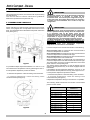
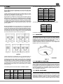
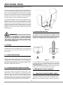
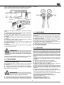
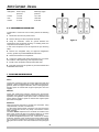
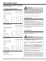
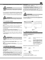
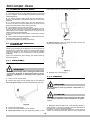
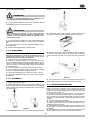
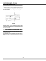
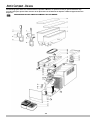
ARCTIC SERVICE MANUAL Compact -Deluxe SERVICE MANUAL Arctic Compact - Deluxe 2 SERVICE MANUAL 4 USER MANUAL 10 TROUBLE SHOOTING 26 3 Arctic Compact - Deluxe 1 INTRODUCTION IMPORTANT Like all mechanical products, this machine will require cleaning and maintenance. This Service Manual contains maintenance guidelines dedicated to qualified service personnel only. Rotating the setting screw of the thermostats completely counterclockwise it is possible to switch off the thermostat itself. This will stop the refrigeration only on single bowl units. On multiple bowls units it is necessary to switch all the thermostats off in order to stop the refrigeration. 2 TEMPERATURE CONTROLS All the units with12 or 20 litres bowls, both Deluxe and Compact series, are equipped with one adjustable thermostat for each bowl. The thermostats are located behind the panel under each bowl (see figure 1). IMPORTANT On multiple bowls units the thermostats are electrically wired in parallel and they directly drive the compressor. It is necessary that all the bowls reach the set temperature to stop the refrigeration (all the thermostats electrically open). It is enough that only in one bowl the temperature is higher than the setting to start the refrigeration (only one thermostat electrically closed). To adjust temperature on multiple bowls machines it is necessary to adjust all the thermostats together at the same setting. On multiple bowls units independent temperature adjustment for each bowl is not available. For Artic Compact 5 and 8 series the situation is the following: Arctic Compact 5-8/1 are equipped with one thermostat to control the themperature of the bowl. Arctic Compact 5-8/2 are equipped only with one thermostat to control the temperature of the bowl at the right. Arctic Compact 5-8/3 are equipped only with one thermostat to control the temperature of the central bowl. Arctic Compact 5-8/4 are equipped with two thermostats to control the temperature of the first and the third bowl from right. The thermostats are always located behind the faucet side panel under the coresponding bowl. This means that the refrigeration on and off depend from the setting of the temperature only of the bowls equipped with the thermostats. It is possible to set the temperature between 6 °C and 12 °C. On new machines the temperature is factory preset approx at 8°C. For temperature adjustment proceed as follows: figure 1 It is possible to adjust temperature between 6 °C and 12 °C. On new machines the temperature is factory preset approx at 8°C. For temperature adjustment proceed as follows: - to decrease temperature: rotate the setting screw clockwise. - to decrease temperature: rotate the setting screw clockwise. - to increase temperature: rotate the setting screw counterclockwise (see figure 2). - to increase temperature: rotate the setting screw counterclockwise (see figure 2) Independent temperature setting for each bowl is not possible. The following table summarizes the number of thermostats present on each model: MODEL Arctic Compact 5/1 - 8/1 figure 2 4 NUMBER OF THERMOSTAS 1 Arctic Compact 5/2 - 8/2 1 - RIGHT BOWL Arctic Compact 5/3 - 8/3 1 - CENTRAL BOWL Arctic Compact 5/4 - 8/4 2 - FIRST AND THIRD BOWLS Arctic Compact 12/1 - 20/1 1 Arctic Compact 12/2 - 20/2 2 Arctic Compact 12/3 - 20/3 3 Arctic Compact 12/4 - 20/4 4 Arctic Deluxe 12/1 - 20/1 1 Arctic Deluxe 12/2 - 20/2 2 Arctic Deluxe 12/3 - 20/3 3 Arctic Deluxe 12/4 - 20/4 4 3 PUMPS The following table summarizes all the available bowls: Arctic Deluxe series dispensers are equipped with spray pumps. Each pump is magnetically driven by an independent electric motor. These machines are equipped with one Main Switch to power ON and OFF refrigeration and with one Pump Switch for each bowl (see user manual for controls details). Spray pumps are suitable for a large variety of products but it is better not to spray coffee, tea, natural juices or other beverages that can foam. To avoid spray on these machines it is necessary to replace the original impeller with a different one (grey impeller pn 33900-01201) and to remove the spray tube from the bowl. In addition the original bowl can be replaced with a dedicated one (pn 22900-00010 or 22900-04810) to perform even more gentle agitation. PART NUMBER BOWLS CAPACITY [litres] MIXING SYSTEM 22900-01900 5 SPRAY 22900-01910 5 SUBMERGED 22900-02000 8 SPRAY 22900-02010 8 SUBMERGED 22900-00000 12 SPRAY 22900-00010 12 SUBMERGED 22900-04800 20 SPRAY 22900-04810 20 SUBMERGED And the following one specifies all the available spray tubes: Arctic Compact series dispensers are equipped with submerged pumps. On double machines the pumps are driven by only one motor through a transmission belt and three pulleys. This motor also works as a fan. On triple machines two pumps are driven by one motor with the same system of double units and the third is driven by a single motor. On four bowls machies the pumps are driven by two motors (see figure 3). PART NUMBER BOWLS CAPACITY [litres] 22900-00202 5 22900-00203 8 22900-00201 12 22900-00200 20 Combined configuration can be realized for particular needings. 3. 1 IMPELLERS The impeller must spin freely on its pivot to perform efficient mixing and cooling. For this purpose keep clean both the impeller and the pivot from traces of sugar, pulp or other. If necessary, lube the parts with food grade lubricant. A self-lubricating washer is moulded into the bottom of the impeller. Regularly check this part and, if worn, replace the impeller with a new one (see figure 4). figure 3 These machines are equipped only by one Main Switch to power ON and OFF all the functions, refrigeration and pumps. figure 4 Submerged pumps are suitable for almost all kind of beverages and particularly for coffee, tea, natural juices or other beverages that can foam. In case of need it is possible to equip Arctic Compact dispensers with spray pumps replacing the impellers (pn 33900-01204 or 33900-01205), the bowls (pn 22900-01900, 22900-02000, 22900-00000 and 22900-04800) and installing the spray tubes. 3. 2 MAGNETIC COUPLING The impellers are magnetic coupled with their respective motors. The magnetic gap is factory preset and does not require to be adjusted. In case of loss of magnetic lock, one or more of the following problems can be present: bent pump motor bracket due to a transport shock, impeller improper spinning due to worn, damaged or dirty parts. The following table summarizes all the available impellers: PART NUMBER COLOUR BOWLS CAPACITY [litres] MIXING SYSTEM VOLATGE 33900-01200 WHITE 33900-01201 GREY 12, 20 SPRAY 230V 50HZ, 240V 50HZ 33900-01204 BLUE 5, 8 12, 20 SPRAY SPRAY 230V 50HZ, 240V 50HZ 115V 60HZ, 220V 60HZ 33900-01205 RED 5, 8 SPRAY 115V 60HZ, 220V 60HZ 3. 3 NOISY IMPELLERS In case of noisy impellers, it is necessary first of all to remove them from the pivots and power the unit on. If the noise is still present it is necessary to power the unit off, unplug it and remove the panels in order to check the pumps motors assemblies. Possible causes of noise can be the following: faulty electric motor, improper magnetic alignment due to a bent 5, 8, 12, 20 SUBMERGED 230V 50HZ, 240V 50HZ 115V 60HZ, 220V 60HZ 5 Arctic Compact - Deluxe bracket, fan blade not rotating free from obstacles or some lose component vibrating during machine working. On Arctic Compact with multiple bowls it is necessary also to remove the transmission belt from the pulleys and power on the unit. If the noise is still present the cause can be the electric motor once again. Otherwise, if the noise is not present anymore, it is necessary to remove the magnetic pulleys assemblies and check for the integrity of their ball bearings. If necessary replace the entire magnetic pulley assembly. If, removing the impellers, the noise is not present anymore it means that the cause of can be in the impellers or in the magnetic coupling. Check for worn impellers and if necessary replace them. Clean the impellers and the pivots and if necessary lubricate them with food grade lubricant. Install the impellers and put some water into the bowls. If the noise do not disappear it is necessary to check once again the pump motor bracket planarity. figure 5 5 SLOW MIXING SYSTEM IMPORTANT The dispensers of Arctic Deluxe series are available also with slow mixers. Two kind of slow mixers are available: one with magnetic driving (A) and the other with mechanic driving (B). The first one is suitable for delicate drinks like tea or coffee while the other one is suitable also for thick drinks (see figure 6). The impellers are designed to spin always submerged and wet. It is very important to avoid to have them spinning dry to prevent worn out. For this reason on Arctic Deluxe always switch off pump of empty bowls and on Arctic Compact remove the impeller of empty bowls or fill them with water. 4 FAUCETS Two different faucets are available both for Arctic Deluxe and Arctic Compact series: pinch tube faucet and stainless steel gravity faucet. 4. 1 PINCH TUBE FAUCET This faucet is suitable for all kind of products, liquid or thick, with or without pulp or other solid particles. In case of dripping, it is necessary to drain the product out of the bowl, remove the pinch tube, clean it with fresh water and check for wear on it. If necessary, replace it with a new one. figure 6 In case of magnetic slow mixer improper rotation, the cause can be a faulty drive motor, a magnetic mixer that can’t freely rotate on its pivot or ice on the evaporator caused by very low level of product into the bowl. In case of direct slow mixer improper rotation the cause can be a foulty motor or an excessive thickness of the drink. 4. 2 STAINLESS STEEL GRAVITY FAUCET 6 REFRIGERANT CIRCUIT SERVICE This faucet is suitable for liquid product without pulps or other solid particles. In case of dripping, it is necessary to drain the product out of the bowl, remove the stainless steel piston, clean it with fresh water and check for wear of the rubber gasket. If necessary, replace it with a new one. It is also necessary to clean the piston housing in the bottom of the bowl and check for the integrity of the rim around the piston hole (see figure 5). 6. 1 CHECKING FOR REFRIGERANT LEAKS The following procedure is the recommended approach to systematically inspect the entire system for refrigerant leaks NOTE: when using refrigerant detector, follow along the bottom 6 side of the copper tubing since the refrigerant gas is heavier than air. Where copper tubing is protected by an insulating jacket, check for leaks at both ends of each jacket section. . figure 8) figure 7 figure 8 Referring to the diagram (see figure 7), perform the following steps: 1 Start inspection at the high pressure line of the compressor. Check around the soldered connection. 2 Follow the copper tubing to the condenser and check around the soldered connections at the top and bottom of the condenser. 3 Check also along the copper curves on both sides of condenser. 4 Follow the copper tubing to the evaporators, checking around the soldered connections of dryer. 5 Remove mixer motors and check the inlet (capillary) and outlet (suction) tubing. 6 Check the copper tubing all the way back to the compressor. 7 Check around the low side connections of the compressor suction and process tubes. 6. 3 EVACUATING Always install a brand new liquid line filter dryer before evacuating. 1 Connect the REF port of the gauge set to the charging unit. 2 Connect the VAC port of the gauge set to the vacuum pump and open the VAC valve. 3 Open the line valve of the charging unit and, for a while, also the REF valve, so as to purge air from the REF hose. 4 Open the LOW valve of the gauge set and turn on the vacuum pump for a minimum of half an hour. 5 While the pump is running, close the VAC valve once a vacuum has been established. 6 Turn off the vacuum pump. 6. 4 CHARGING IMPORTANT The gauge set is usually with four ports and four valves (see figure 8). This is the easiest option to be found in the market since it allows the charging through both low and high side of the system. Our refrigeration systems are manufactured so as to be chargeable through the compressor process tube only (low side): thus, the HI port is never mentioned nor used in the following procedure and therefore the HI valve must be kept closed. 1 Determine how many ounces/grams should be filled by the charging unit. This information can be found on the dispenser data plate. 2 Remove bowls and mixers from the dispenser. 3 Plug in the dispenser and turn on the power switch. 4 Open the line valve of the charging unit. 5 Open the REF valve very slowly so as to allow the refrigerant to be pulled into the system as a gas. 6 When the amount of refrigerant listed on the data plate has been used, the system is charged. Close the REF valve and the charging unit line valve and allow the compressor to run few minutes. 7 Ensure that all evaporator plates are covered with frost. 8 Close the LOW valve, disconnect the LOW hose from the compressor process tube and tighten the screw cap. To check for a leak in the low side of the system, it is advisable to have the evaporators at least at ambient temperature. If a leak has been detected, seal it and make a new refrigerant charge as per instructions in the following paragraphs. 6. 2 DISCHARGING 1 Remove the dispenser panels. 2 If not present install a charging valve on the compressor process tube. 3 Remove the screw cap from the compressor process tube. 4 Connect the process tube to the LOW part of the gauge set. 5 Connect the VAC port of the gauge set to an adequate approved gas recovery system. ATTENTION The following table reports the suction and discharge pressures of the machines with the different refrigerants. They must be verified under the following conditions: Ambient temperature: 32 °C Product temperature in the bowls: 5 °C Evaporation temperature approx -5 °C Condensation temperature approx 50°C. The refrigerant gas could be highly acid and toxic. 6 Open the LOW and VAC valves and recover the refrigerant. 7 Once the recovery operation is completed, close the LOW and VAC valves and disconnect the recovery system.(see 7 Arctic Compact - Deluxe Refrigerant Suction (low) pressure Discharge (high) pressure R134a 1,43 bar 12,17 bar R22 3,20 bar 18,39 bar R404a 4,10 bar 21,93 bar 6. 5 COMPRESSOR BURN-OUT To determine if a burn-out has occurred, perform the following steps: 1 Disconnect the unit from power source. 2 Remove wiring from the compressor terminals. figure 9 3 Using an ohmmeter, check for ground between the terminals and the compressor housing. If a reading exists, the compressor has shorted to ground. In this case compressor must be replaced as per following steps: 4 Recover the refrigerant using an approved refrigeration recovery system as per DISCHARGING instructions. 5 Remove the burned-out compressor. 6 Correct the system fault which caused the burn-out. Check the condition of the capacitor(s) and compressor relay. 7 Install a new compressor and liquid line filter dryer. 8 Evacuate and charge the system as per EVACUATING and CHARGING instructions. 7 ROUTINE MAINTENANCE DAILY Inspect the machine for signs of product leaks past seals and gaskets. If proper assembly does not stop leaks around seal or gaskets, check for improper lubrication, worn or damaged parts. Replace parts as needed with original spare parts from the supplier. WEEKLY Clean and sanitize the machine following the procedures illustrated on the Operator's Manual of the unit. Check for worn impellers, bowl gaskets, faucet pinch tubes or stainless steel piston gaskets. Replace parts as needed with original spare parts from the supplier. MONTHLY Clean all internal components, primarily the condenser, using compressed air, vacuum or a soft brush. To clean these internal parts, unplug the unit and remove the panels. Condenser fins are very sharp. Use extreme caution when cleaning. On Arctic Deluxe dispensers the condenser is located on the back of the unit and air flow is from back to sides (A). To clean the condenser it is necessary to remove the back panel. On Arctic Compact dispensers the condenser is always located on the back of the unit but air flow if from sides to back (B). To clean the condenser it is necessary to remove the faucet side panel and to clean it from the inside of the unit (see figure 5). 8 9 Arctic Compact - Deluxe The following key operation procedures, extracted from the Operator’s Manual, are quoted here too so that service personnel may help end users to achieve the best performances and results. IMPORTANT 1 TECHNICAL CHARACTERISTICS Read electrical ratings written on the data plate of the individual units; the data plate is adhered on the dispensing side panel of the unit, just behind the drip tray (the right side drip tray in multiple bowl models). The serial number of the unit (preceded by the symbol #) is adhered just below the right bowl. Data plate specifications will always supersede the information in this manual. ARCTIC COMPACT 5/8 lt 1/5 1/8 2/5 2/8 3/5 3/8 4/5 4/8 Transparent removable bowls n 1 2 3 4 Capacity of each bowl, approx. l 5 8 5 8 5 8 5 8 cm 18 25 37 50 Dimensions: width depth cm 40 40 40 40 5 lt 8 lt cm 55 63 55 63 55 63 55 63 Net weight, approx. 5 lt 8 lt kg 13 13 15 17 21 21 23 23 Gross weight, approx. 5 lt 8 lt kg 15 15 17 19 23 23 26 26 n 1 1 1 2 1/12 1/20 2/12 2/20 3/12 3/20 4/12 4/20 height Adjustable thermostats Specifications are subject to change without notice. 2 INTRODUCTION Please read all sections of this manual thoroughly to familiarize yourself with all aspects of the unit. Like all mechanical products, this machine will require cleaning and maintenance. Besides, dispenser working can be compromised by operator’s mistakes during disassembly and cleaning. It is strongly recommended that personnel responsible for the equipment’s daily operations, disassembly, cleaning, sanitizing and assembly, go through these procedures in order to be properly trained and to make sure that no misunderstandings exist. ARCTIC COMPACT 12/20 lt Transparent removable bowls n 1 2 3 4 Capacity of each bowl, approx. l 12 20 12 20 12 20 12 20 width cm 18 36 54 72 depth cm 47 47 47 47 12 lt 20 lt cm 61 71 61 71 61 71 61 71 Net weight, approx. 12 lt 20 lt kg 20 22 24 32 36 42 44 55 Gross weight, approx. 12 lt 20 lt kg 22 25 28 36 40 46 49 59 n 1 2 3 4 Dimensions: height Adjustable thermostats 3 INSTALLATION 1 Remove the corrugate container and packing materials and keep them for possible future use. IMPORTANT When handling the machine never grasp it by the bowls or by the evaporator cylinders. The manufacturer refuses all responsibilities for possible damages which may occur through incorrect handling. ARCTIC DELUXE 12/20 lt 1/12 1/20 2/12 2/20 3/12 3/20 4/12 4/20 Transparent removable bowls n 1 2 3 4 Capacity of each bowl, approx. l 12 20 12 20 12 20 12 20 2 Inspect the uncrated unit for any possible damage. If damage is found, call the delivering carrier immediately to file a claim. width cm 18 36 54 72 depth cm 47 47 47 47 12 lt 20 lt cm 57 67 57 67 57 67 57 67 3 Install the unit on a counter top that will support the combined weight of dispenser and product bearing in mind what is stated in the preceding point 1 IMPORTANT warning. Net weight, approx. 12 lt 20 lt kg 20 22 24 32 36 42 44 55 Gross weight, approx. 12 lt 20 lt kg 22 25 28 36 40 46 49 59 n 1 2 3 4 Dimensions: height Adjustable thermostats 4 A minimum of 15 cm (6”) of free air space all around the unit should be allowed to guarantee adequate ventilation. 5 Ensure that the legs are screwed tightly into the base of the machine. Replace the standard legs originally installed with the 100 mm (4”) legs whenever they are provided with the unit. Hermetic compressor 6 Before plugging the unit in, check if the voltage is the same as that indicated on the data plate. Plug the unit into a grounded, protected single phase electrical supply according to the applicable electrical codes and the specifications of your machine. Should you prefer to connect the unit directly to the mains, connect the supply cord to a 2-pole wall breaker, whose Air-cooled condenser Overload protector Noise level lower than 70 dB (A) 10 over the bowls. 5 Set the control switches as shown in chapter 5.1 DESCRIPTION OF CONTROLS. 6 The dispenser must always run with the covers installed to prevent a possible contamination of the product. 7 Always leave the dispenser on, as the refrigeration stops automatically when the beverage reaches the dispensing temperature. The mixing devices will continue to turn. 8 To maintain a high standard of flavour, keep refrigeration and mixing devices on during the night when beverage is in the bowl. contact opening is at least 3 mm. Do not use extension cords. ATTENTION Failure to provide proper electrical ground according to applicable electrical codes could result in serious shock hazard. 7 The unit doesn’t come presanitized from the factory. Before serving products, the dispenser must be disassembled, cleaned and sanitized according to this handbook instructions (chapter 5.3 CLEANING AND SANITAZING PROCEDURES). IMPORTANT Operate the dispenser with food products only. 9 On Arctic Deluxe series machines equipped with lighted top covers it is necessary to turn the cover for 180 degrees to switch light off. (see figure 1) IMPORTANT Install the dispenser so that the plug is easily accessible. 4 TO OPERATE SAFELY 1 Do not operate the dispenser without reading this operator’s manual. 2 Do not operate the dispenser unless it is properly grounded. 3 Do not use extension cords to connect the dispenser. 4 Do not operate the dispenser unless all panels are restrained with screws. 5 Do not obstruct air intake and discharge openings: 15 cm (6”) minimum air space all around the dispenser. 6 Do not put objects or fingers in panels louvers and faucet outlet. 7 Do not remove bowls, augers and panels for cleaning or routine maintenance unless the dispenser is disconnected from its power source. figure 1 5. 1 DESCRIPTION OF CONTROLS The dispenser is equipped with a power switch and each bowl is operated by a mixing device switch. Their functions are as follows: Power switch ATTENTION 0 position In case of damages, the power cord must be replaced by qualified personnel only in order to prevent any shock hazard. : Power is turned OFF to all functions. On Arctic Deluxe series this position operates the fan : motor and makes the mixing devices suitable to be turned on by relevant switches. On arctic Compact series this position operates all the funtions of the dispenser. 8 This unit is not meant to be used outside. 9 This unit is not to be installed in areas subject to waterspouts.. 10 Do not use water-jets to clean the unit. 11 This unit can work in a room temperature range between +5° and +32°C. I position 5 OPERATING PROCEDURES Mixing device switch (Arctic Deluxe series only) 1 Clean and sanitize the unit according to the instructions in this manual. See chapter 5.3 CLEANING AND SANITIZING PROCEDURES. 2 Fill the bowls with product to the maximum level mark. Do not overfill. The exact quantity of product (expressed as liters and gallons) is shown by marks on the bowl. 3 In case of products to be diluted with water, potable water, pour water into bowl first, then add correct quantity of product. In case of natural squashes, it is advisable to strain them, in order to prevent pulps from obstructing the faucet outlet. 4 Install the covers and check that they are correctly placed 0 position : OFF. I position : Mixing device runs. To operate the dispenser 1 Set power switch to I position. 2 Set mixing device switch(es) to I position. 11 Arctic Compact - Deluxe 5. 2 OPERATION HELPFUL HINTS take the pinch tube off from its seat (2) (see figure 3). 1 The length of time for cooling down the product is governed by many variables, such as ambient temperature and beverage initial temperature. 2 To shorten product cooling down time and increase productivity, it is advisable to pre-chill the product to be used in the dispenser. 3 To shorten product cooling down time and increase productivity, the bowl should be refilled after the product level drops lower than half and at the start of each day. 4 The dispenser must be able to emit heat. In case it seems excessive, check that no heating source is close to the unit and air flow through the slotted panels is not obstructed by wall or boxes. Allow at least 15 cm (6”) of free clearance all around the dispenser. In any case if the product in the bowls is cold the unit is running properly. 5 How to reset beverage temperature:to reset beverage temperature please apply to a technician. The proper temperature is preset at the factory. figure 3 6 Gravity faucet: extract the piston and then remove the dispensing handle (see figure 4). 5. 3 CLEANING AND SANITIZING PROCEDURES Cleaning and sanitizing of the dispenser are recommended to guarantee the conservation of the best product taste and the highest unit efficiency. This section is a procedural guideline only and is subject to the requirements of the local Health Authorities. Prior to the disassembly and cleaning, the machine must be emptied of product. 5. 3. 1 DISASSEMBLY ATTENTION figure 4 Before any disassembly and/or cleaning procedure make sure that the dispenser is disconnected from its power source by unplugging it or switching off the 2-pole wall breaker. 7 Slide drip tray out and empty it. 5. 3. 2 CLEANING 1 Remove cover from the bowl. 2 Remove the empty bowl by pulling lever (1) and lifting its front side (faucet side) up and off bowl gasket (see figure 2). IMPORTANT Do not attempt to wash any machine components in a dishwasher. ATTENTION Before any disassembly and/or cleaning procedure make sure that the dispenser is disconnected from its power source. figure 2 1 Prepare at least two gallons of a mild cleaning solution of warm (45-60 °C 120-140 °F) potable water and dishwashing detergent. Do not use abrasive detergent. Important: if present, follow label directions, as too strong a solution can cause parts damage, while too mild a solution will 3 Remove the bowl gasket. 4 Remove the pump impeller from its location. 5 Pinch tube faucet: push the dispensing handle (1) and 12 its gasket (see figure 6). not provide adequate cleaning. IMPORTANT In order to prevent any damages to the dispenser, use only a detergent suitable with plastic parts. 2 Using a brush, suitable for the purpose, thoroughly clean all disassembled parts in the cleaning solution. ATTENTION figure 6 4 Fit the bowl gasket to the evaporator. Note: the larger brim of the gasket must face against the drip plate (see figure 7). When cleaning the machine, do not allow excessive amounts of water around the electrically operated components of the unit. Electrical shock or damage to the machine may result. 3 Do not immerse the lighted top covers in liquid. Wash them apart with the cleaning solution. Carefully clean their undersides. 4 In the same manner clean the evaporator plate(s) using a soft bristle brush. 5 Rinse all cleaned parts with cool clean water. figure 7 5. 3. 3 SANITIZING 5 Place bowl on the unit. Wet the gasket for ease of insertion. Please take care that the hook on the backside of the bowl be inserted properly in its seat on the upper drip plate. (see figure 8). Sanitizing should be performed immediately prior to starting the machine. Do not allow the unit to sit for extended periods of time after sanitization. 1 Wash hands with a suitable antibacterial soap. 2 Prepare at least two gallons of a warm (45-60 °C 120140 °F) sanitizing solution (100 PPM available chlorine concentration or 1 spoon of sodium hypoclorite diluted with two litres of water) according to your local Health Codes and manufacturer’s specifications. 3 Place the parts in the sanitizing solution for five minutes. 4 Do not immerse the lighted top covers in liquid. Carefully wash their undersides with the sanitizing solution. 5 Place the sanitized parts on a clean dry surface to air dry. 6 Wipe clean all exterior surfaces of the unit. Do not use abrasive cleaner. figure 8 5. 3. 4 ASSEMBLY 6 Use fresh product to chase any remaining sanitizer from the bowl(s). Drain this solution. Do not rinse out the machine. 1 Slide the drip tray into place. 2 Pinch tube faucet: push the dispensing handle (1) and insert the pinch tube into its vertical seat in the bowl bottom(2). Lightly pull the pinch tube end downwards til it is well arranged (3) (see figure 5). 5. 4 IN-PLACE SANITIZATION Daily: The In-Place Sanitization prior to starting the machine may be performed, if needed, only as further precaution, in addition to the Disassembled Parts Sanitization described before, but never in lieu of it. 1 Prepare two gallons of a warm (45-60°C, 120-140 °F) sanitizing solution (100 PPM available chlorine concentration or 1 spoon of sodium hypoclorite diluted with two litres of water) according to your local Health Codes and manufacturer’s specifications. 2 Pour the solution into the bowl(s). 3 Using a brush suitable for the purpose, wipe the solution on all surfaces protruding above the solution-level and on the underside of the top cover(s). 4 Install the top cover(s) and operate the unit. Allow the solution to agitate for about two minutes. Drain the solution out of the bowl(s). 5 Use fresh product to chase any remaining sanitizer from the bowl(s). Drain this solution. Do not rinse out the machine. figure 5 3 Gravity faucet: install the faucet handle and the piston with 13 Arctic Compact - Deluxe 6 ROUTINE MAINTENANCE 1 Replacement of lighted top cover bulbs (see figure 9) : - Remove the fixing screws placed in the upper part of the top cover, - remove the lower part and replace the bulbs (using a 2428V 21W max bulbs). - Reassemble the top cover and replace the fixing screws. figure 9 2 Daily: inspect the machine for signs of product leaks past seals and gaskets. If proper assembly does not stop leaks around seals or gaskets, check for improper lubrication, worn or damaged parts. Replace parts as needed with original spare parts from the supplier. 6. 1 MAINTENANCE (TO BE CARRIED OUT BY QUALIFIED SERVICE PERSONNEL ONLY) Montly: clean all internal components, primarily the condenser, using compressed air. To clean these internal parts, unplug the unit or switch off the 2pole wall breaker, then remove front panel (dispensing side). Condenser fins are very sharp. Use extreme caution when cleaning. 14 15 Arctic Compact - Deluxe The following Spare Parts List, extracted from the Operator’s Manual, are quoted here too for general reference only. To order spare parts please make refernece to the Spare Part List included in the Operator’s Manual supplied with each dispenser. SPARE PARTS LIST ARCTIC COMPACT 5/8 LT MODEL 16 4 5 7 8 9 11 12 13 14 15 16 17 21 22 23 24 27 29 30 31 22800-21900 10028-02500 22900-02010 21703-00000 22900-01910 10029-00000 22900-00500 22900-00800 22900-00501 22800-02600 22900-01300 22900-01300 22800-17200 33900-01201 22900-00600 22040-00000 21087-00000 10554-45000 21125-00000 Faucet piston Faucet gasket 8 It bowl Pinch tube 5 It bowl Picture Push handle Faucet cover Push handle Faucet spring 8 It bowl cover 5 It bowl cover Bowl gasket Impeller Central pivot Central pivot OR Thermostat Clip Cabinet Switch 32 33 34 35 36 37 37A 38 39 40 41 42 43 44 45 46 47 48 49 Please order what printed on piece 33900-01052 22800-05100 22900-03602 22800-02201 22800-04800 22800-18921 22900-03011 22800-12700 22800-05500 22800-10000 33800-00803 22800-04800 22800-04706 Pulley, magnet and spacer assembly Switch cap Belt Driving pulley Motor bracket Fan/pump motor for 1 bowl Fan/pump motor for 2, 4 bowls Fan Relay Overload protector Terminal block cover Terminal block with cable clamp Rubber leg Dispensing side panel Drip tray cover Drip tray Motor magnet for 1, 3 bowls Motor bracket Pump motor 3 bowls See table 30 38 44 45 46 1/.. 22900-03210 22900-00403 22900-03110 22800-00500 22800-00602 2/.. 22900-03211 22900-00401 22900-03111 22800-00510 22800-00611 3/.. 22900-03212 22900-00401 22900-03112 22800-00510 22800-00611 4/.. 22900-03213 22900-00401 22900-03113 22800-00510 22800-00611 WIRING DIAGRAM ARCTIC COMPACT 5/8 LT MODEL 17 1/5-8 - 2/5-8 - 3/5-8 1 2 3-5 4 Switch Thermostat Pump/mixer Compressor 4/5-8 1 2-3 4-6 5 Switch Thermostat Pump/mixer Compressor Arctic Compact - Deluxe The following Spare Parts List, extracted from the Operator’s Manual, are quoted here too for general reference only. To order spare parts please make refernece to the Spare Part List included in the Operator’s Manual supplied with each dispenser. SPARE PARTS LIST ARCTIC COMPACT 12/20 LT MODEL 18 1 2 3 4 5 6 7 8 9 10 11 12 13 14 15 16 17 18 19 20 21 22900-00100 22900-00100 22900-04810 22900-00010 22800-02600 22800-17200 33900-01201 22900-00700 22900-00600 22040-00000 22900-03051 10554-45000 22800-21900 10028-02500 21703-00000 10029-00000 22900-00500 22900-00800 22900-00501 21087-00000 21125-00000 20 It bowl cover 12 It bowl cover 20 It bowl 12 It bowl Faucet spring Bowl gasket Impeller Plastic I-beam for connection Central pivot Central pivot OR Capacitor Clip Faucet piston Faucet gasket Pinch tube Picture Push handle Faucet cover Push handle Thermostat Switch 22 23 24 25 26 27 27A 28 29 30 31 32 33 34 35 36 37 38 39 40 Please order what printed on piece 22800-05100 33900-01051 22900-03601 22800-02201 22800-04800 22800-18921 22900-03001 22800-12700 22800-05500 33800-00803 22800-04800 22800-04706 22800-10000 22900-03700 22900-03800 Switch cap Pulley, magnet and spacer assembly Belt Driving pulley Motor bracket Fan/pump motor for 1 bowl Fan/pump motor for 2, 4 bowls Fan Relay Overload protector Terminal block cover Terminal block with cable clamp Motor magnet for 1, 3 bowls Motor bracket Pump motor 3 bowls Cabinet Rubber leg Dispensing side panel Drip tray cover Drip tray See table 28 36 38 1/.. 22900-00400 22900-03200 22900-03100 2/.. 22900-00402 22900-03201 22900-03101 3/.. 22900-00402 22900-03202 22900-03102 4/.. 22900-00402 22900-03203 22900-03103 WIRING DIAGRAM ARCTIC COMPACT 12/20 LT MODEL 1/12-20 - 2/12-20 - 3/12-20 1 Switch 2-3-4 Thermostat 5-7 Pump/mixer 6 Compressor 4/12-20 1-2 3-4-5-6 7-9 8-10 19 Switch Thermostat Pump/mixer Compressor Arctic Compact - Deluxe The following Spare Parts List, extracted from the Operator’s Manual, are quoted here too for general reference only. To order spare parts please make refernece to the Spare Part List included in the Operator’s Manual supplied with each dispenser. SPARE PARTS LIST ARCTIC DELUXE 12/20 LT MODEL 20 1 22900-00100 20 It bowl cover 51 22900-05600 Driving shaft 12lt 2 22900-00100 12 It bowl cover 51 22900-05601 Driving shaft 20lt 6 22800-17200 Bowl gasket 52 22900-05400 Stirrer 12lt 7 22900-00700 Plastic I-beam for connection 52 22900-05401 Stirrer 20lt 8 22900-00600 Central pivot 53 22900-05500 Central shaft 12lt 9 22040-00000 Central pivot OR 53 22900-05501 Central shaft 20lt 10 33800-00803 Motor magnet 54 10028-01801 tube for central shaft 11 22800-04800 Motor bracket 55 10533-01303 brass nut 12 22800-04706 Motor 56 22900-05700 Central shaft OR. 13 Back panel 57 22900-02504 Pump motor bracket 14 22900-04800 20 l bowl for pump 58 33800-06701 Mixer motor 15 22900-00201 Spray tube for 12 l bowl 59 22900-06200 Top cover upper part 16 22900-00000 12 l bowl for pump 60 10028-04201 Plate holder for 17 33900-01204 Impeller 60Hz 61 10028-04200 Bulb socket 18 22800-02600 Faucet spring 62 10028-03800 28V bulb 19 22900-00200 Bent tube for 20 l bowl 63 22800-11701 Top cover light contact 20 22800-21900 Faucet piston 64 22900-06020 Bottom hat mechanical agitation with light 21 10028-02500 Faucet gasket 64 22900-06030 Bottom hat mechanical agitation without light 22 22900-04820 20 l bowl for stirrer 64 22900-06050 Bottom hat with light insulated 23 21703-00000 Pinch tube 64 22900-06051 Bottom hat without light insulated 24 33900-01202 Stirrer 64 22900-06000 Bottom hat without light not insulated 25 22900-00020 12 l bowl for stirrer 65 22900-06400 Picture 26 10029-00000 Picture 68 33900-02100 Cover complete with light insulated 27 22900-00500 Push handle 68 33900-02200 Cover complete without light insulated 28 22900-00800 Faucet cover 68 33900-02300 Cover complete without light not insulated 29 22900-00501 Push handle 68 33900-01800 Cover with light to complete mechanical shaker 30 21125-00000 Switch 68 33900-01900 Cover complete without light for mechanical shaker 31 22800-05100 Switch cap 32 22800-00300 Side panel 33 22800-12700 Terminal block cover 34 22800-05500 Terminal block with cable clamp 35 Overload protector 36 Relay 37 21907-00000 Fan for 12 lt. 37A 22800-13200 Fan for 20 lt. 38 22800-04706 Fan motor for 12 lt. 38A 22800-04709 Fan motor for 20 lt. 38B 33800-06901 Fan motor for 1 bowl 39 10554-45001 Clip 40 22800-10000 Rubber leg 41 42 10502-55010 Stainless steel fixing screw for panel 43 22900-03700 Drip tray cover 44 22900-03800 Drip tray 45 21087-00000 Thermostat 46 22900-02502 Central pivot 47 22900-02503 Washer 48 33900-01011 Impeller mixer motor 49 22900-03501 Mixer motor 50 22900-02504 Pump motor bracket Dispensing side panel 1/.. 2/.. 3/.. 4/.. 13 22800-06800 22900-02310 22900-02320 22900-02330 41 22800-21600 22800-21700 22800-21800 22900-04100 21 Please order what printed on piece See table Arctic Compact - Deluxe WIRING DIAGRAM ARCTIC DELUXE 12/20 LT MODEL 1-2 Switch 3-4-5-6 Thermostat 7-8-9-10 Pump/mixer switch 11-12-13-14 Pump/mixer 15-16 Fan Motor 17-18 Compressor 19-20 Transformer 21-22-23-24 Top light 22 NOTES: 23 Arctic Compact - Deluxe NOTES: 24 NOTES: 25 Arctic Compact - Deluxe 1 GENERAL TROUBLESHOOTING GUIDE PROBLEM CAUSE No working at all. Neither pump motors, Improper or faulty electrical connection fan motor nor compressor run Defective main switch REMEDY Locate and correct the problem Replace main switch No refrigeration at all. Pump motors and Defective overload protector or relay of Replace overload protector fan motor run but compressor does not compressor run Compressor cycles on overload protector Check the power line for low voltage and then check starting relay and overload protector and if necessary replace them No or poor refrigeration Defective thermostat (always open) Replace thermostat Not enough air flow for ventilation Provide at least 15 cm (6") of free air space all around the unit Condenser clogged with dust Clean the condenser using compressed air, vacuum or a soft brush. Condenser fins are very sharp, use extreme caution Defective fan motor Check for possible obstacles to fan blade rotation. If necessary replace fan motor Poor refrigerant gas charge Detect possible leak, seal it and make new refrigerant charge Excessive refrigeration. Compressor Wrong temperature adjustment never stops. Adjust temperature setting One defective thermostat (always closed) Replace thermostat One thermostat temperature probe out Insert thermostats temperature probes from its housing properly into their housings No pumping or agitation, pump motor Pump impeller does not spin at all runs Clean both impeller and pivot from traces of product and if necessary lubricate them with food grade grease. Pump impeller does not spin freely on Check for worn impeller and if necessary pivot replace it. Magnetic lock decoupling (chattering) No pumping or agitation, pump motor Improper or faulty electrical connection doesn't run Verify planarity of pump motor bracket Locate ad correct the problem Defective pump switch Replace pump switch Defective pump motor Replace pump motor Drive magnet binds on evaporator Verify planarity of pump motor bracket assebly Broken transmission belt (Arctic Compact Replace transmission belt series with multiple bowls only) Leak from bowls B o w l f a s t e n i n g h o o k n o t p r o p e r l y Engage bowl fastening hooks engaged Bowl gasket wrongly fitted Fit bowl gasket properly around its seat Nicked or wrong bowl gasket Replace bowl gasket Dripping from faucets (pinch tube faucet) Damaged or worn pinch tube. Faucet handle out of closing position 26 Replace pinch tube Check faucet handle and/or its spring, replacing whichever damaged PROBLEM CAUSE REMEDY Dripping from faucets (gravity stainless Nicked or wrong stainless steel gravity Replace stainless steel piston gasket steel faucet) piston gasket Noisy unit Faucet piston out of closing position Check for stainless steel piston free movement. If necessary clean both piston and bowl housing. Check for faucet handle free movement, if necessary replace faucet handle Bowls faucet rim damaged Replace bowl Worn impellers Replace impellers Bent fan blade Re-bent fan blade to correct aligment Noisy fan or pump motor Replace noisy motor Magnetic lock decoupling (chattering) Verify planarity of pump motor bracket Noisy ball bearings (Arctic Compact Replace magnetic pulley assembly series with multiple bowls only) No magnetic slow mixer rotation Defective drive motor Replace drive motor Magnetic mixer does not rotate freely on Clean both mixer and pivot from traces of pivot product and if necessary lubricate them with food grade grease No mechanic slow mixer rotation Ice on the evaporator Increase product level into the bowl Adjust temperature setting Check thermostats Defective drive motor Replace drive motor Product excessive thicknes 27 Ugolini spa 2428_02 V0.4 14N01 • Via dei Pioppi, 33 • 20090 Opera (MI) • Tel. 02.5300591 • www.ugolinispa.com