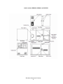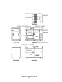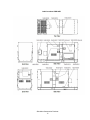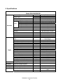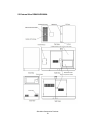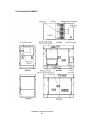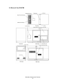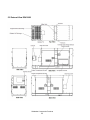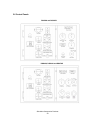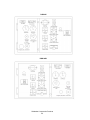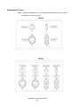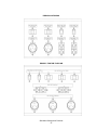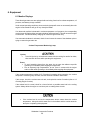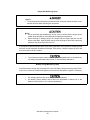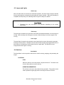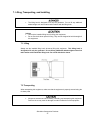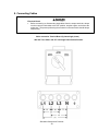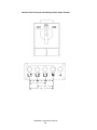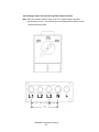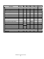
1
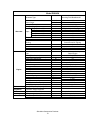
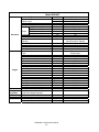
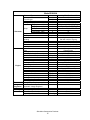
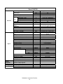
Owners Manual
Sound Attenuated Diesel
Generator Sets
WARNING!
CALIFORNIA – Proposition 65 Warning
Diesel engine exhaust and some of its
constituents are known to the State of
California to cause cancer, birth defects, and
other reproductive harm.
1/6/05 Part No. 80350
Table of Contents
1. INTRODUCTION ----------------------------------------------------------------------------------------4
2. SAFETY GUIDELINES --------------------------------------------------------------------------------5
3. WARNING LABELS------------------------------------------------------------------------------------7
Label Locations DGK25A/DGK25B ------------------------------------------------------------------------------8
Label Locations DGK45A, DGK60A, and DGK70B ----------------------------------------------------------9
Label Locations DGK45C----------------------------------------------------------------------------------------- 10
Label Locations DGK100B --------------------------------------------------------------------------------------- 11
4. SPECIFICATIONS ------------------------------------------------------------------------------------ 12
Model DGK25A/DGK25B ----------------------------------------------------------------------------------------- 12
Model DGK45A------------------------------------------------------------------------------------------------------ 13
Model DGK45C ----------------------------------------------------------------------------------------------------- 14
Model DGK60A------------------------------------------------------------------------------------------------------ 15
Model DGK70B------------------------------------------------------------------------------------------------------ 16
Model DGK100B ---------------------------------------------------------------------------------------------------- 17
5. OUTLINE DRAWINGS ------------------------------------------------------------------------------ 18
5.1 External View DGK25A/DGK25B -------------------------------------------------------------------------- 18
5.2 External View DGK45A/DGK60A -------------------------------------------------------------------------- 19
5.3 External View DGK45C -------------------------------------------------------------------------------------- 20
5.4 External View DGK70B--------------------------------------------------------------------------------------- 21
5.5 External View DGK100B ------------------------------------------------------------------------------------- 22
5.6 Control Panels-------------------------------------------------------------------------------------------------- 23
5.7 Main Terminal Board ------------------------------------------------------------------------------------------ 25
5.8 Receptacle Panels--------------------------------------------------------------------------------------------- 26
6. EQUIPMENT ------------------------------------------------------------------------------------------- 28
6.1 Monitor Displays ----------------------------------------------------------------------------------------------- 28
Coolant Temperature Monitoring Lamp -------------------------------------------------------------------- 28
Engine Oil Monitoring Lamp ---------------------------------------------------------------------------------- 29
Battery Charge Monitoring Lamp ---------------------------------------------------------------------------- 29
6.2 Meters and Gauges ------------------------------------------------------------------------------------------- 30
Hour Meter -------------------------------------------------------------------------------------------------------- 30
Volt Meter---------------------------------------------------------------------------------------------------------- 30
Ammeter ----------------------------------------------------------------------------------------------------------- 30
Frequency Meter------------------------------------------------------------------------------------------------- 30
Coolant Temperature Gauge---------------------------------------------------------------------------------- 30
Oil Pressure Gauge --------------------------------------------------------------------------------------------- 30
Fuel Gauge-------------------------------------------------------------------------------------------------------- 30
6.3 Lamps and Lights ---------------------------------------------------------------------------------------------- 31
Glow Lamp -------------------------------------------------------------------------------------------------------- 31
Pilot Lamp --------------------------------------------------------------------------------------------------------- 31
Panel Light -------------------------------------------------------------------------------------------------------- 31
6.4 Switches --------------------------------------------------------------------------------------------------------- 31
Start Switch ------------------------------------------------------------------------------------------------------- 31
Voltmeter Selector Switch ------------------------------------------------------------------------------------- 32
Ammeter Selector Switch-------------------------------------------------------------------------------------- 32
Shindaiwa Construction Products
1
Voltage Selector Switch---------------------------------------------------------------------------------------- 32
Panel Light Toggle Switch------------------------------------------------------------------------------------- 32
Emergency Stop Switch --------------------------------------------------------------------------------------- 32
6.5 Output Circuit Breaker---------------------------------------------------------------------------------------- 33
6.6 Voltage Adjustment Knob ------------------------------------------------------------------------------------ 33
6.7 Three Way Fuel Valves--------------------------------------------------------------------------------------- 33
6.7.1 Using Fuel From The Internal Tank --------------------------------------------------------------------- 33
6.7.2 Using Fuel From The External Fuel Tank ------------------------------------------------------------- 35
6.7.3 Three Way Valves Locations ----------------------------------------------------------------------------- 36
7. LIFTING, TRANSPORTING, AND INSTALLING---------------------------------------------- 37
7.1 Lifting ------------------------------------------------------------------------------------------------------------- 37
7.2 Transporting----------------------------------------------------------------------------------------------------- 37
7.3 Installing --------------------------------------------------------------------------------------------------------- 38
8. CONNECTING CABLES---------------------------------------------------------------------------- 39
9. INITIAL STARTUP AND PRE-CHECKS -------------------------------------------------------- 43
9.1 Checking Engine Oil ------------------------------------------------------------------------------------------ 43
9.2 Selecting the Proper Engine Oil---------------------------------------------------------------------------- 44
9.3 Checking Engine Coolant ----------------------------------------------------------------------------------- 44
9.3.1 Checking Radiator Level/ Adding Coolant --------------------------------------------------------- 45
9.3.2 Checking the Coolant Reservoir Tank Level/ Adding Coolant -------------------------------- 45
9.4 Checking the Fan Belt---------------------------------------------------------------------------------------- 45
9.4.1 Tension ----------------------------------------------------------------------------------------------------- 46
9.4.2 Condition--------------------------------------------------------------------------------------------------- 46
9.5 Checking the Fuel Level ------------------------------------------------------------------------------------- 46
9.6 Checking for Leaks-------------------------------------------------------------------------------------------- 46
9.7 Checking the Battery ----------------------------------------------------------------------------------------- 47
10. OPERATION------------------------------------------------------------------------------------------ 48
10.1 Starting --------------------------------------------------------------------------------------------------------- 48
10.2 Loading the Generator-------------------------------------------------------------------------------------- 48
10.3 Operating the Generator ----------------------------------------------------------------------------------- 49
10.4 Stopping the Generator------------------------------------------------------------------------------------- 49
10.5 Automatic Shutdowns--------------------------------------------------------------------------------------- 49
10.6 Connecting to an External Fuel Tank ------------------------------------------------------------------- 50
11. MAINTENANCE ------------------------------------------------------------------------------------- 51
11.1 Oil Change----------------------------------------------------------------------------------------------------- 53
Frequency--------------------------------------------------------------------------------------------------------- 53
Procedure --------------------------------------------------------------------------------------------------------- 53
11.2 Oil Filter Change --------------------------------------------------------------------------------------------- 53
Frequency--------------------------------------------------------------------------------------------------------- 53
Procedure --------------------------------------------------------------------------------------------------------- 53
11.3 Cleaning/Changing the Air Filter Element -------------------------------------------------------------- 53
Frequency--------------------------------------------------------------------------------------------------------- 53
Procedure --------------------------------------------------------------------------------------------------------- 53
11.4 Cleaning/Changing the Fuel Filter ----------------------------------------------------------------------- 54
Frequency--------------------------------------------------------------------------------------------------------- 54
Procedure --------------------------------------------------------------------------------------------------------- 54
11.5 Draining Water From the Internal Fuel Tank----------------------------------------------------------- 54
Shindaiwa Construction Products
2
Frequency --------------------------------------------------------------------------------------------------------- 54
Procedure --------------------------------------------------------------------------------------------------------- 54
11.6 Changing Engine Coolant ---------------------------------------------------------------------------------- 54
Frequency --------------------------------------------------------------------------------------------------------- 54
Procedure --------------------------------------------------------------------------------------------------------- 54
12. LONG TERM STORAGE PROCEDURES ---------------------------------------------------- 55
13. TROUBLESHOOTING----------------------------------------------------------------------------- 56
Shindaiwa Construction Products
3
1. Introduction
Thank you for purchasing a Shindaiwa Kwiet Power Sound Attenuated Diesel Generator.
•
•
•
•
This user’s manual was created to help ensure the safe operation of this equipment. The manufacturer
of this equipment strongly recommends that the user follow all of the instructions contained within this
manual to avoid unnecessary accidents or repairs.
Operate this equipment only after thoroughly reviewing and understanding the contents of this manual.
This manual should always be kept on or near the generator.
The battery or batteries supplied with the generator are dry when shipped. Dilute sulfuric acid must be
added.
The following convention will be used throughout this manual to indicate various degrees of
cautions.
May cause severe injuries or death.
May cause minor injuries or damage to the equipment or other property.
Other types of caution.
•
Even some of the items noted in
follow all items and safety guidelines.
may lead to severe injuries. Read and carefully
Shindaiwa Construction Products
4
2. Safety Guidelines
Suffocation from exhaust fumes
• Exhaust fumes from the engine on this diesel generating set contain many elements that have
been proven to be harmful to humans. Do not operate this equipment in poorly ventilated areas
such as inside a room or in a tunnel.
• Do not direct exhaust fumes toward people or buildings.
Electrical Shock
• Do not come in contact with or allow anything else to come in contact with the output terminals
during operation.
• Be sure to place the protective covers over the output terminals and fasten them securely while
operating this equipment.
• Do not insert metal objects (such as pins or wires) into plug-in receptacles.
• Do not touch the wiring or any electrical or electronic parts inside the equipment during
operation.
• There is always a danger of being electrocuted by a short-circuit to ground. Be sure to test the
generator’s insulation resistance to ground periodically.
• Before connecting or disconnecting load cables from the output terminals, always turn the
output circuit breaker to the OFF position, stop the engine, and remove the engine key. The
person performing the cable disconnect should always keep the key.
• Before performing any equipment check or maintenance, stop the engine, and remove the
engine key. The person performing the check or maintenance should always keep the key.
Injuries
• To avoid injuries by unintentional contact with the cooling fan or fan belt, close and lock all
doors while operating this equipment.
• When lifting the equipment, always use the installed lifting hook. The lifting hook is designed
to lift only the generator. Do not lift any additional added weight such as fuel tanks
and/or trailers.
Injuries to eyes and skin
•
Battery fluid contains diluted sulfuric acid. Avoid contact with eyes, skin or clothing. If contact
with the acid does occur, especially with the eyes, flush immediately with large volumes of
water and contact a physician.
Fire
• This equipment uses diesel (a flammable liquid) as a fuel. When refueling, always stop the
engine, and maintain an adequate distance from flames or spark producing devices. Always
wait until the engine cools down before refueling.
• Always immediately wipe up any diesel fuel or engine oil that is spilled. Do not use this
equipment if there are any leaks. Repair the equipment before further use.
• Temperatures around the muffler and exhaust piping can get extremely high. Keep any
flammable items (such as fuel, gas, paint, etc.) away from these areas.
Shindaiwa Construction Products
5
•
The battery may emit highly explosive gases. Never expose it to flames or spark producing
devices.
• This equipment must be operated only on flat surfaces and at least 3 feet away from any
obstructions (such as walls) that could hinder airflow.
• Do not connect the AC output to any indoor wiring without an approved disconnecting device
between the generator and the building’s electrical service.
Burns
• To avoid sustaining burns from hot vapor, do not open the radiator cap while operating or
immediately after stopping this equipment.
• Due to extremely high temperatures, do not touch the engine or muffler while operating or
immediately after stopping the equipment.
• When checking or changing engine oil, always stop the engine, and wait until the engine cools
down. Opening either the line to the oil gauge or the oil filler cap during operation may cause
severe burns due to hot oil.
Injuries
• Do not use the tie downs for lifting. They are not designed to hold the weight of the equipment
and using them for lifting may cause the equipment to fall.
• Always place the equipment on a flat and stable surface to keep it from sliding.
• When starting the engine, disconnect the supplied load and set the output circuit breaker to the
OFF position.
• Do not move the equipment during operation.
• When performing equipment checks and/or maintenance, always stop the engine.
• Do not operate this equipment if it is being modified or if any parts have been removed.
WARNING KEEP TERMINAL BLOCK FREE OF DUST AND
MOISTURE AT ALL TIMES!!
Always keep environmental contaminants such as dust and moisture from building up on the
terminal block and generator control box or arcing from the terminals to the generator control
box or terminal block mounting screws may result.
Shindaiwa Construction Products
6
3. Warning Labels
Caution, Danger, Warning and Operation Information Labels: Make sure all information labels are
undamaged and readable. Immediately replace damaged or missing information labels. New labels are
available from your local authorized Shindaiwa distributor or dealer.
Type
Danger - Injury
Caution – Potential
Property Damage
Caution – Potential
Property Damage
Danger - Injury
Caution - Fire
Danger - Poisoning
Danger - Injury
Caution – Burns
Danger – Electric
Shock
Caution - Burns
Instructional
Location (s)
Adjacent to each tie down on the enclosure top.
Text:
Do not lift this equipment with this tie down.
Directly above the fuel drain plug on the enclosure panel.
Text:
Never remove fuel drain plug without proper containment and
disposal method for fuel.
Near or on the voltage selector switch.
Text:
Do not change voltage switch while the generator is running.
On each side of the lifting hook on the enclosure top.
Text:
Lifting hook designed to lift only the generator.
Do not lift any additional added weight such as fuel tanks
and/or trailers with this lifting hook.
Directly under the fuel fill cover. On the back enclosure panel on the
DGK25B, on the left rear enclosure panel on the DGK45A,
DGK60A and DGK100B, and on the right rear enclosure panel on
the DGK45C.
Text:
Stop the engine and maintain an adequate distance from flames or
spark producing devices while refueling.
Allow the engine to cool down before refueling.
On the control panel door directly under the access handle or on
the top right on the DGK45C.
Text:
Do not operate this equipment without adequate ventilation.
On the engine compartment access door.
Text:
To avoid accidental contact with moving parts, close and lock all
doors while operating this equipment.
On the engine compartment access door and near the radiator fill
cap access door on the enclosure top.
Text:
Do not come in contact with this area while the engine is operating
or immediately after engine operation.
On the output terminal access door and near the output terminals.
Text:
Do not come in contact with the output terminals while this
equipment is operating. Turn the main circuit breaker to off and stop
the engine before servicing.
Near the radiator fill cap access door on the enclosure top.
Text:
Do not open the radiator cap while operating or immediately after
stopping this equipment.
Immediately above the fuel fill cover.
Text:
Diesel Fuel (ASTM No. 2-D)
Shindaiwa Construction Products
7
Part Number
19402-00207
19402-00208
19402-00209
19402-00210
19402-00211
19402-00212
19402-00213
19402-00214
19402-00215
19402-00216
19401-00251
Label Locations DGK25A/DGK25B
Shindaiwa Construction Products
8
Label Locations DGK45A, DGK60A, and DGK70B
Shindaiwa Construction Products
9
Label Locations DGK45C
Shindaiwa Construction Products
10
Label Locations DGK100B
Shindaiwa Construction Products
11
4. Specifications
Model DGK25A/DGK25B
Generator Type
Alternator
Rated Output
Voltage – Three phase
Voltage – Single phase
Single phase - 120V
Single phase - 240V
Amps
Three phase – 208V
Three phase - 240V
Three phase - 480V
Frequency
Rated speed
kVA
kW
V
V
A
A
A
A
A
Hz
rpm
Winding
Power factor
Insulation class
Excitation
No. of poles
Engine
Meters
Voltage
Regulation
Shutdowns
Warning
Unit
Type
Model (Manufacturer)
No. of Cylinders (bore x stroke)
Continuous rated output
Rated speed
Displacement
Combustion system
Cooling method
Lubricating method
Starting method
Fuel
Lubricating oil
Fuel tank capacity
Lubricant volume
Cooling water volume
Starting motor capacity
Charging alternator capacity
Battery capacity
Voltage/Frequency/Amperage/Hour
(in./mm)
hp
rpm
cu. in./liters
gal./liters
gal./liters
gal./liters
V-kW
V-A
V-AH
Automatic Voltage Regulator
Oil pressure, Water temperature
Battery charge
Dimensions (L x W x H)
in./mm
Dry weight
lbs./kg
Shindaiwa Construction Products
12
Revolving Field Brushless AC
25
20
240, 480
120, 240, 277
55 (4-wire); 62 X 2 (Zig Zag)
27 (4-wire); 62 (Zig Zag)
60
60
30
60
1800
3-phase, 4-wire
Star with neutral / Zig-zag
.8
F
Static excitation (brushless)
4
Vertical Water-cooled 4-cycle
Diesel Engine
4LE1 (ISUZU)
4 (3.35 x 3.78/85 x 96)
31
1800
133/2.179
Swirl chambered
Radiator
Forced lubrication
Electric
Diesel
CC class or higher
17.2/65
2.2/8
2.3/8.6
12V-1, 8kW
12V-20A
12V-70AH
Lamp indication with shutdown
Lamp indication
68.9 x 25.6 x 36/1750 x 650 x
915
1360/617
Model DGK45A
Generator Type
Alternator
Revolving Field Brushless AC
Rated Output
Voltage – Three phase
Voltage – Single phase
Single phase - 120V
Single phase - 240V
Amps
Three phase – 208V
Three phase - 240V
Three phase - 480V
Frequency
Rated speed
kVA
kW
V
V
A
A
A
A
A
Hz
rpm
gal./liters
gal./liters
gal./liters
V-kW
V-A
V-AH
45
36
240, 480
120, 240, 277
100 (4-wire); 112 X 2 (Zig-Zag)
50 (4-wire); 112 (Zig Zag)
108
108
54
60
1800
3-phase, 4-wire
Star with neutral / Zig-zag
.8
F
Static excitation (brushless)
4
Vertical Water-cooled 4cycle
Diesel Engine
4BG1 (ISUZU)
4 (4.13 x 4.92/105 x 125)
56
1800
264.2/4.329
Direct Fuel Injection
Radiator
Forced lubrication
Electric
Diesel
CC class or higher
26.4/100
3.8/14.02
7.1/27
24V-1, 4.5 kW
24V-20A
12V (2) -80AH
in./mm
lbs./kg
Lamp indication with shutdown
Lamp indication
74x34.6x48.8/1880x880x1240
2544/1154
Winding
Power factor
Insulation class
Excitation
No. of poles
Engine
Meters
Voltage
Regulation
Shutdowns
Warning
Unit
Type
Model (Manufacturer)
No. of Cylinders (bore x stroke)
Continuous rated output
Rated speed
Displacement
Combustion system
Cooling method
Lubricating method
Starting method
Fuel
Lubricating oil
Fuel tank capacity
Lubricant volume
Cooling water volume
Starting motor capacity
Charging alternator capacity
Battery capacity
Voltage/Frequency/Amperage/Hour
Automatic Voltage Regulator
Oil pressure, Water temperature
Battery charge
Dimensions (L x W x H)
Dry weight
(in./mm)
hp
rpm
Cu .in./liters
Shindaiwa Construction Products
13
Model DGK45C
Generator Type
Alternator
Rated Output
Voltage – Three phase
Voltage – Single phase
Single phase - 120V
Single phase - 240V
Amps
Three phase - 240V
Three phase - 480V
Frequency
Rated speed
kVA
kW
V
V
A
A
A
A
Hz
rpm
Winding
Power factor
Insulation class
Excitation
No. of poles
Engine
Meters
Voltage
Regulation
Shutdowns
Warning
Unit
Type
Model (Manufacturer)
No. of Cylinders (bore x stroke)
Continuous rated output
Rated speed
Displacement
Combustion system
Cooling method
Lubricating method
Starting method
Fuel
Lubricant oil
Fuel tank capacity
Lubricant volume
Cooling water volume
Starting motor capacity
Charging alternator capacity
Battery capacity
Voltage/Frequency/Amperage/Hour
Automatic Voltage Regulator
Oil pressure, Water temperature
Battery charge
Dimensions (L x W x H)
Dry weight
(in./mm)
hp
rpm
Cu .in./liters
gal./liters
gal./liters
gal./liters
V-kW
V-A
V-AH
in./mm
lbs./kg
Shindaiwa Construction Products
14
Revolving Field Brushless AC
45
36
240, 480
120, 240, 277
225 (4-wire)
112.5 (4-wire)
108.3
54.1
60
1800
3-phase, 4-wire
Star with neutral / Zig-zag
.8
F
Static excitation (brushless)
4
Vertical Water-cooled 4cycle
Diesel Engine
4JG1T (ISUZU)
4 (3.75 x 4.21/95.4 x 107)
57
1800
186.7/3.059
Direct Fuel Injection
Radiator
Forced lubrication
Electric
Diesel
CC class or higher
32.8/124
2.6/10
3.4/13
12V, 2.2 kW
12V-50A
12V-80AH
Lamp indication with shutdown
Lamp indication
69.7x36.2X53.1/1770x920x1350
2513/1140
Model DGK60A
Generator Type
Alternator
Rated Output
Voltage – Three phase
Voltage – Single phase
Single phase - 120V
Single phase - 240V
Amps
Three phase – 208V
Three phase - 240V
Three phase - 480V
Frequency
Rated speed
kVA
kW
V
V
A
A
A
A
A
Hz
rpm
Winding
Power factor
Insulation class
Excitation
No. of poles
Engine
Meters
Voltage
Regulation
Shutdowns
Warning
Unit
Type
Model (Manufacturer)
No. of Cylinders (bore x stroke)
Continuous rated output
Rated speed
Displacement
Combustion system
Cooling method
Lubricating method
Starting method
Fuel
Lubricating oil
Fuel tank capacity
Lubricant volume
Cooling water volume
Starting motor capacity
Charging alternator capacity
Battery capacity
Voltage/Frequency/Amperage/Hour
Automatic Voltage Regulator
Oil pressure, Water temperature
Battery charge
Dimensions (L x W x H)
Dry weight
(in./mm)
hp
rpm
cu in/liters
gal./liters
gal./liters
gal./liters
V-kW
V-A
V-AH
in./mm
lbs./kg
Revolving Field Brushless AC
60
48
240, 480
120, 240, 277
133(4-wire);150 X 2 (Zig Zag)
66 (4-wire); 150 (Zig Zag)
144
144
72
60
1800
3-phase, 4-wire
Star with neutral / Zig-zag
.8
F
Static excitation (brushless)
4
Vertical Water-cooled 4-cycle
Diesel Engine
4BG1T (ISUZU)
4 (3.35 x 3.78/85 x 96)
78
1800
133/2.179
Direct Injection, Turbocharger
Radiator
Forced lubrication
Electric
Diesel (ASTM No. 2-D)
CD class or higher
33/125
3.8/14.2
7.1/27
24V-1, 4.5 kW
24V-20A
12V (2) -80AH
Lamp indication with shutdown
Lamp indication
78.3x34.6x48.8/1990x880x1240
2681/1216
Shindaiwa Construction Products
15
Model DGK70B
Generator Type
Alternator
Rated Output
Voltage – Three phase
Voltage – Single phase
Single phase - 120V
Single phase - 240V
Amps
Three phase - 240V
Three phase - 480V
Frequency
Rated speed
Winding
Power factor
Insulation class
Excitation
No. of poles
Motor Starting Capability
Engine
Meters
Voltage
Regulation
Shutdowns
Warning
Unit
Type
Model (Manufacturer)
No. of Cylinders (bore x stroke)
Continuous rated output
Rated speed
Displacement
Combustion system
Cooling method
Lubricating method
Starting method
Fuel
Lubricant oil
Fuel tank capacity
Fuel Consumption
Full Load
75%
50%
25%
Lubricant volume
Cooling water volume
Starting motor capacity
Charging alternator capacity
Battery capacity
Voltage/Frequency/Amperage/Hour
Automatic Voltage Regulator
Oil pressure, Water temperature
Battery charge
Dimensions (L x W x H)
Dry weight
gal./liters
gal./liters
gal./liters
gal./liters
gal./liters
gal./liters
gal./liters
V-kW
V-A
V-AH
Revolving Field Brushless AC
70
56
240, 480
120,139, 240, 277
155.5 (4 wire), 168x2(Zig-zag)
77.8 (4 wire), 168(Zig-zag)
168
84
60
1800
3-phase, 4-wire
Star with neutral / Zig-zag
.8
H
Static excitation (brushless)
4
XXX sKVA (30% Voltage Drop)
Vertical Water-cooled 4cycle Diesel
Engine
4BG1T (ISUZU) EPA2
4 (4.13 x 4.92/105 x 125)
82
1800
264.2/4.329
Direct Fuel Injection, Turbo Charger
Radiator
Forced lubrication
Electric
Diesel
CD class or higher
33/125
4.39/16.6
3.33/12.6
2.38/9.0
1.51/125
3.8/5.7
4.5/17
12V, 2.5 kW
12V-60A
12V-80AH
in./mm
lbs./kg
Lamp indication with shutdown
Lamp indication
82.3x34.6X48.8/2090x880x1240
2745/1245
kVA
kW
V
V
A
A
A
A
Hz
rpm
sKVA
(in./mm)
hp
rpm
Cu .in./liters
Shindaiwa Construction Products
16
Model DGK100B
Generator Type
Alternator
Rated Output
Voltage – Three phase
Voltage – Single phase
Single phase - 120V
Single phase - 240V
Amps
Three phase – 208V
Three phase - 240V
Three phase - 480V
Frequency
Rated speed
kVA
kW
V
V
A
A
A
A
A
Hz
rpm
Winding
Power factor
Insulation class
Excitation
No. of poles
Type
Model (Manufacturer)
No. of Cylinders (bore x stroke)
Continuous rated output
Rated speed
Displacement
Engine
Meters
Voltage
Regulation
Shutdowns
Warning
Unit
Combustion system
Cooling method
Lubricating method
Starting method
Fuel
Lubricant oil
Fuel tank capacity
Lubricating volume
Cooling water volume
Starting motor capacity
Charging alternator capacity
Battery capacity
Voltage/Frequency/Amperage/Hour
Automatic Voltage Regulator
Oil pressure, Water temperature
Battery charge
Dimensions (L x W x H)
Dry weight
(in./mm)
hp
rpm
cu
in/liters
Revolving Field Brushless AC
100
80
240, 480
120, 240, 277
214 (4 Wire); 241 X 2 (zig zag)
107(4 Wire); 241 (zig zag)
241
241
120
60
1800
3-phase, 4-wire
Star with neutral / Zig-zag
.8
F
Static excitation (brushless)
4
Vertical Water-cooled 4-cycle
Diesel Engine
6BG1TC (ISUZU)
6/(4.13 x 4.92/105 x 125)
150.2
1800
396.3/6.494
gal./liters
gal./liters
gal./liters
V-kW
V-A
V-AH
Direct Injection, Turbo Charged,
Inter Cooled
Radiator
Forced lubrication
Electric
Diesel (ASTM No. 2-D)
CC class or higher
57.9/219
2.2/8
5.6/21.3
12V, 4.5kW
24V-30A
12V(2)-80AH
in./mm
lbs./kg
Lamp indication with shutdown
Lamp indication
113x39.4x55.1/2870x1000x1400
4079/1850
Shindaiwa Construction Products
17
5. Outline Drawings
5.1 External View DGK25A/DGK25B
Shindaiwa Construction Products
18
5.2 External View DGK45A/DGK60A
Shindaiwa Construction Products
19
5.3 External View DGK45C
Shindaiwa Construction Products
20
5.4 External View DGK70B
Shindaiwa Construction Products
21
5.5 External View DGK100B
Shindaiwa Construction Products
22
5.6 Control Panels
DGK25A and DGK25B
DGK45A, DGK60A and DGK70B
Shindaiwa Construction Products
23
DGK45C
DGK100B
Shindaiwa Construction Products
24
5.7 Main Terminal Board
Shindaiwa Construction Products
25
5.8 Receptacle Panels
Note: All duplex receptacles are GFCI protected and are rated at 20 amps. All Twist Loc
receptacles are rated at 50 amps.
DGK25A
DGK25B
Shindaiwa Construction Products
26
DGK45A and DGK60A
DGK45C / DGK70B / DGK100B
Shindaiwa Construction Products
27
6. Equipment
6.1 Monitor Displays
These diesel generator sets are equipped with monitoring functions for coolant temperature, oil
pressure, and battery charge condition.
Under normal operating conditions, these monitoring lamps will come on momentarily when the
engine is first started but will go off very shortly thereafter.
If an abnormal condition is detected in coolant temperature or oil pressure, the corresponding
monitor lamp will flash and the automatic shutdown will be activated. This will cause the engine
to shut down. Insufficient battery charging will cause the light to flash only.
If an automatic shutdown is activated, check for and correct the cause of the shutdown prior to
trying to restart the generator set.
Coolant Temperature Monitoring Lamp
Injuries
•
To avoid injuries by unintentional contact with the cooling fan and/or fan belts,
close and lock all doors while operating this equipment.
Burns
• To avoid sustaining burns from hot vapor, do not open the radiator cap while
operating or immediately after stopping this equipment.
• Due to extremely high temperatures, do not come in contact with the engine
and/or muffler while operating or immediately after stopping this equipment.
If the coolant temperature reaches 212º Fahrenheit increasing during operation, the coolant
temperature monitoring lamp will flash, and the automatic shutdown will activate.
If this occurs, check the coolant reservoir tank, and replenish coolant if needed (refer to 9.3
Checking Engine Coolant).
If the coolant level is normal, check for a loose fan belt or possible water leak in the cooling
system. Always allow the engine to cool down prior to making these checks.
•
If the coolant level is too low, the temperature sensor cannot detect the coolant
temperature. Always check the water level in the radiator and the coolant reservoir
tank prior to operating this equipment.
Shindaiwa Construction Products
28
Engine Oil Monitoring Lamp
Injuries
• To avoid injuries by unintentional contact with the cooling fan and/or fan belts, close
and lock all doors while operating this equipment.
Burns
• Due to extremely high temperatures, do not come in contact with the engine and/or
muffler while operating or immediately after stopping this equipment.
• When checking or changing engine oil, always stop the engine and wait until the
engine cools down. Opening either the line to the oil gauge or the oil filler cap during
operation may cause injury due to hot oil.
If the engine oil pressure drops below 10 psi during operation, the oil pressure monitoring lamp
will flash, and the automatic shutdown will activate. If this occurs, check the engine oil level, and
fill to the maximum level if needed.
•
The oil pressure sensor cannot detect engine oil degradation due to extended use.
Oil change intervals listed under section 11 must be strictly adhered to.
Battery Charge Monitoring Lamp
Insufficient battery charge during operation will cause the battery charge monitoring lamp to flash.
If this occurs, check the condition and tightness of the fan belt and replace or tighten if necessary.
•
•
For changing the belt, refer to the engine Workshop Manual.
The Battery Charge Monitor cannot detect the degradation of battery life or the
battery fluid level (refer to 9.7 Checking the Battery).
Shindaiwa Construction Products
29
6.2 Meters and Gauges
Hour Meter
The hour meter keeps track of run time. This meter should be used to schedule preventive
maintenance. Note: The hour meter will continue to operate as long as the start switch is in the
ON position, regardless of whether the engine is actually running or not.
Volt Meter
The volt meter displays the voltage output from the generator. The voltage displayed will be
dependent on the position of the voltage selector switch. For single-phase operation it will display
L1 or L3 voltage only.
Ammeter
The amp meter displays the electrical current output from the generator. The amperage displayed
will be dependent on the position of the amp meter selector switch. For single-phase operation it
will display L1 or L3 phase amperage only.
Frequency Meter
The frequency meter will display the frequency of the generated power.
Coolant Temperature Gauge
This gauge indicates the temperature of the engine coolant in degrees Fahrenheit.
normal operating conditions this gauge should read approximately 180 °F to 200 °F.
Under
Oil Pressure Gauge
This gauge indicates the oil pressure of the engine in pounds per square inch. Under normal
operating conditions this gauge should read approximately 40 to 60 pounds per square inch.
Fuel Gauge
This gauge indicates the fuel level in the internal fuel tank only. If there is an external fuel tank
being used to supply fuel to the generator this gauge will not indicate the fuel level of that tank.
Shindaiwa Construction Products
30
6.3 Lamps and Lights
Glow Lamp
When the start switch is turned to the Run/Preheat position, the Glow Lamp will light to indicate
that the glow plugs are energized and preheating the engine cylinders. When the preheating is
completed, the lamp will go off, indicating that the engine is ready to be started.
•
Preheating time may vary from 1 to 5 seconds, depending on the coolant
temperature.
Pilot Lamp
The pilot lamp is located on the generator control panel and indicates whether or not the engine is
running. When the lamp is lit the engine is running. When the lamp is not lit the engine is not
running.
Panel Light
The panel light is located on the generator control panel and is used to illuminate the generator
and engine control panels. This light is turned on and off with the panel light toggle switch which is
also located on the generator control panel next to the panel light. This light can only be
energized when the engine is running.
6.4 Switches
Start Switch
The Start Switch is a three position switch that is used for starting, stopping, and preheating the
engine.
POSITIONS:
STOP:
When the switch is set to this position, all power will be off. The switch must
be set to this position to remove the key.
OPERATING/PREHEATING:
The switch must be set to this position during operation. This position is also
used to preheat the glow plug and for removing air from the fuel lines.
Shindaiwa Construction Products
31
•
Do not leave the switch in this position, while the engine is stopped. It
may drain the battery.
START:
This position allows the user to start the engine. When the operator
releases the key while in this position, the switch will automatically return
to the Operating/Preheating position.
Voltmeter Selector Switch
The voltmeter selector switch is a 5 position switch located on the generator control panel next
to the voltmeter that selects which phase voltage the voltmeter will be displaying. There are two
off positions for this switch, one at the far left position and one at the far right position. In the off
positions the voltmeter will not be displaying any voltage. In the L1-L2 position the voltmeter will
display the phase voltage between phase L1 and phase L2. In the L2-L3 position the voltmeter
will display the phase voltage between phase L2 and phase L3. In the L3-L1 position the
voltmeter will display the phase voltage between phase L3 and phase L1. This switch must be
in the L1-L3 position to read single phase voltage.
Ammeter Selector Switch
The ammeter selector switch is a 5 position switch located on the generator control panel next
to the ammeter that selects which phase current the ammeter will be displaying. There are two
off positions for this switch, one at the far left position and one at the far right position. In the off
positions the ammeter will not be displaying any amperage. In the L1 position the ammeter will
display phase L1 current. In the L2 position the ammeter will display phase L2 current. In the
L3 position the ammeter will display phase L3 current. This switch must be in the L1 or L3
position to read single phase current.
Voltage Selector Switch
The voltage selector switch is a lockable 3 position switch located directly above the terminal
connection panel. This switch provides a quick, convenient method of changing the generator
output voltage. This switch should never be operated while the generator is running. The Three
Phase 480/277 position gives an output from the generator of 480 volts three phase or 277 volts
single phase. The Three Phase 240/139 position gives an output from the generator of 240
volts three phase or 139 volts single phase. The Single Phase 240/120 volt position gives a
single phase output from the generator of 240 volts or 120 volts.
Panel Light Toggle Switch
This switch is located on the generator control panel next to the Panel Light. It is used to turn
the panel light on and off. To prevent leaving this light on and draining the battery, this switch
can only turn the Panel Light on when the generator is running.
Emergency Stop Switch
This switch is installed on the DGK45C, DGK70B, and DGK100B and is located just to the left of
the start/stop switch on the engine control panel. It is a red momentary contact type switch that
will immediately stop the engine when it is pushed.
Shindaiwa Construction Products
32
6.5 Output Circuit Breaker
The Output Circuit Breaker is located on the control panel and is used for connecting and
disconnecting the load from the output of the generator. Turning the circuit breaker to the ON
position will allow power to be supplied to the load. Turning the circuit breaker to the OFF
position will remove all power from the load. The breaker will also trip and remove power from
the load in the event that there is an overload condition on the generator.
6.6 Voltage Adjustment Knob
The Voltage Adjustment Knob is used to adjust the generated output voltage of the generator.
Turning the voltage adjust knob clockwise will increase the generated voltage. Turning the
voltage adjust knob counter-clockwise will decrease the generated voltage. The adjustment
range available with this knob is plus 6.5% and minus 15%.
6.7 Three Way Fuel Valves
Burns
• Always stop the engine prior to performing any work on fuel lines.
• Immediately wipe up any fuel leakage.
The 3-Way valves provide a quick and convenient method of using an external fuel tank as a fuel
supply for the engine. If an external fuel supply is being used, the internal fuel tank is not available
as a supply of fuel for the engine.
6.7.1 Using Fuel From The Internal Tank
The 3-way valve is set to the A position when the equipment is shipped. This position
allows the fuel from the internal tank to be used as a fuel source for the engine. In
addition, both the external fuel intake and the external fuel return lines are plugged with
3/8 inch pipe plugs. Always ensure that the external fuel intake and return are plugged
with the supplied plugs or is connected to an external fuel tank while using the internal
fuel tank as the fuel source.
Always set the 3-way valve back to the A position and cover the external fuel intake and
fuel return ports with the supplied plugs, whenever the internal fuel tank is being used as
the fuel source.
Shindaiwa Construction Products
33
3- Way Valve Fuel Return Line in the A Position (Using Internal Fuel Tank)
3- Way Valve Fuel Suction Line in the A Position (Using Internal Fuel Tank)
Shindaiwa Construction Products
34
6.7.2 Using Fuel From The External Fuel Tank
Connect hoses from the external fuel tank to the external fuel intake and the
external fuel return ports, and set the 3-way valve to the B position. You can now
supply fuel from the external fuel tank. For detailed instructions, (refer to Section
10.6 Connecting to an External Fuel Tank).
3- Way Valve Fuel Return Line in the B Position (Using External Fuel Tank)
3- Way Valve Fuel Suction Line in the B Position (Using External Fuel Tank)
Shindaiwa Construction Products
35
6.7.3 Three Way Valves Locations
The Three Way Valves are located on the right side of the generator enclosure (when
viewed from the control panel end), very near the enclosure upright. They are enclosed
within the generator bed frame. On the DGK45C they are located on the left side of the
generator enclosure. They are a distinctive orange color with black directional arrow
markings.
Shindaiwa Construction Products
36
7. Lifting, Transporting, and Installing
•
The lifting hook is designed to lift only the generator. Do not lift any additional
added weight such as fuel tanks and/or trailers with the lifting hook.
Injuries
• Use only the installed lifting hook for lifting this equipment.
• Do not use the tie down posts for lifting. They are not designed to hold the weight of
this equipment.
7.1 Lifting
Always use the installed lifting hook, whenever lifting this equipment. This lifting hook is
designed to lift only the generator. Do not lift any additional added weight such as fuel
tanks and/or trailers with this lifting hook. Do not lift with the tie downs.
7.2 Transporting
When transporting this equipment, make sure that the equipment is properly secured using the
tie down posts.
•
Always use extreme care when loading, unloading, and transporting this equipment.
Failure to do so may result in damages to and/or malfunction of the equipment.
Shindaiwa Construction Products
37
7.3 Installing
Suffocation from exhaust fumes
• Exhaust fumes from the engine on this equipment contain many elements that
have been proven to be harmful to humans. Do not operate this equipment in
poorly ventilated areas such as inside a room or in a tunnel.
• Do not direct exhaust fumes toward pedestrians or buildings.
Fire
• This equipment must be operated only on flat surfaces and at least 3 feet away from
any obstructions (such as walls) that could hinder airflow.
• Temperatures around the muffler and exhaust piping can get extremely high. Keep
any flammable items (such as fuel, gas, paint, etc.) away from these areas.
•
•
•
This equipment must be operated on a hard and flat surface. Operating under any
other conditions may result in damage to or malfunctions of the equipment.
Do not block the airflow from the radiator output or muffler exhaust. This may result
in reduced engine performance, overheating, or other significant damage.
Operating in abnormally dusty, salty or high particulate environments may result in
fouling of the radiator or air cleaner. The frequency of maintenance and operating
checks should be increased when operating this equipment in these types of
environments.
Shindaiwa Construction Products
38
8. Connecting Cables
Electrical Shock
• Before connecting or disconnecting load cables from the output terminals, always
turn the output circuit breaker to the OFF position, stop the engine, and remove the
engine key. The person performing the connection or disconnection should always
keep the key.
Cable connection Terminal Board (3-phase/single phase)
480 Volt Three Phase and 277 Volt Single Phase Switch Position
Shindaiwa Construction Products
39
240 Volt Three Phase and 139 Volt Single Phase Switch Position
Shindaiwa Construction Products
40
208 Volt Three Phase and 120 Volt Single Phase Switch Position
Shindaiwa Construction Products
41
240 Volt Single Phase and 120 Volt Single Phase Switch Position
Note: Place the voltmeter selector switch in the L3-L1 position and the ammeter
selector switch in the L1 or L3 position when the Voltage Selector Switch is in the
1 Phase 240/120V position.
Shindaiwa Construction Products
42
9. Initial Startup and Pre-Checks
Electrical Shock
• Prior to performing any equipment check or maintenance, stop the engine and
remove the engine key. The person performing the equipment check or
maintenance should always keep the key.
Burns
• Prior to performing any engine checks or adjustments, stop the engine. Wait until
the engine cools down, before performing any checks or adjustments.
Fire
• Always immediately wipe up any spilled or dripped fuel or oil. If a leak is found, do
not use this equipment until the cause of the leak has been determined and
remedied. Complete repairs to the equipment before further use.
9.1 Checking Engine Oil
(Also, please refer to the accompanying Instruction Manual for the engine)
When checking the engine oil, be sure to keep the equipment level and insert the dipstick fully.
Prior to starting the engine, make sure to fill the engine oil to the MAX line through the oil filler
tube.
•
•
If the equipment is not level, you cannot obtain an accurate oil level reading.
Do not overfill the engine with oil. Too much engine oil could damage the engine.
1. Remove the dipstick from the crankcase and wipe it clean with a clean cloth.
2. Reinsert it fully and then gently remove it again.
3. Check the oil level on the dipstick. The level must be between the “Max” level mark
and the “Min” level mark.
4. If the level is above the “Max” mark, drain oil until the level is at or below the “Max”
level mark.
5. If the level is at or below the “Min” level mark, add oil until the level is above the “Min”
level mark.
Shindaiwa Construction Products
43
9.2 Selecting the Proper Engine Oil
Use engine oil specifically designed for diesel engine use with the proper viscosity based on the
anticipated ambient temperature (refer to the chart below).
Oil Viscosity and Temperature
Temperature °F
-22°
5°
32°
60°
77°
86°
SAE10W-30
SAE10W
SAE30W
SAE20/20W
SAE40W
SAE 15W-40/20W-40
•
Use API class CC grade or higher engine oil.
9.3 Checking Engine Coolant
(Also, please refer to the accompanying Instruction Manual for the engine)
Injuries
• Prior to performing any equipment check or maintenance, stop the engine, and
remove the engine key. The person performing the equipment check or
maintenance should always keep the key.
Burns
• To avoid sustaining burns from hot vapor, do not open the radiator cap while
operating or immediately after stopping this equipment.
• Due to extremely high temperatures, do not touch the engine or muffler while
operating or immediately after operation of this equipment.
Shindaiwa Construction Products
44
9.3.1 Checking Radiator Level/ Adding Coolant
(Also, please refer to the accompanying Instruction Manual for the engine)
1. Remove the radiator cap which is located under the removable plate bolted on the
top of the generator top cover. The coolant level should be up to the filler port neck.
If not, add coolant. The coolant should be a 50/50 mix of GM SPEC 6277M or
equivalent long life Coolant/Water.
2. Fill the radiator with coolant until it reaches the filler port neck. Fill slowly to prevent
air entry.
3. Reinstall the radiator cap and tighten.
4. Recheck the level after a few minutes of running the engine and refill if necessary.
9.3.2 Checking the Coolant Reservoir Tank Level/ Adding Coolant
(Also, please refer to the accompanying Instruction Manual for the engine)
1. Ensure the coolant level is between the MIN and the MAX line.
2. If the coolant level is low, add the same mixture of coolant used in the radiator to fill
the reservoir tank to the MAX line.
•
•
Always use potable water when mixing coolant.
Do not spill antifreeze or engine coolant on the exhaust system or hot
engine parts. Under some conditions the long life coolant is combustible.
9.4 Checking the Fan Belt
(Also, please refer to the accompanying Instruction Manual for the engine)
Injuries
• Before performing any equipment check or maintenance, stop the engine,
and remove the engine key. The person performing the equipment check
or maintenance should always keep the key.
• To avoid injuries by unintentional contact with the cooling fan or fan belt,
close and lock all doors while operating this equipment.
Burns
Due to extremely high temperatures, do not touch the engine or muffler while
operating or immediately after stopping the equipment.
Shindaiwa Construction Products
45
9.4.1 Tension
The fan belt should have ¼ to ½ inch slack when applying finger pressure at the
midpoint between the fan pulley and the alternator pulley.
9.4.2 Condition
Check the fan belt for any damage and replace if necessary.
•
Refer to the Instruction Manual for the engine to adjust or replace the fan
belt.
9.5 Checking the Fuel Level
Fire
• Always immediately wipe up any diesel fuel or engine oil that is spilled. Do not use
this equipment if there are any leaks. Repair the equipment before further use.
Prior to starting the engine check the level of the fuel in the tank that is currently supplying fuel.
The fuel gauge on the control panel shows only the level of the fuel in the internal tank (three way
valves in the A position). If an external fuel tank is connected and being used as the fuel source
three way valves in the B position), the fuel level in this tank is monitored and read separately from
the gauge on the control panel.
•
•
Ensure the fuel strainer is installed in the neck of the fill spout.
Fill the tank to slightly less than the FULL mark.
9.6 Checking for Leaks
Fire
• Do not use this equipment if there are any leaks. Repair the equipment before
further use.
• Check all hose connections for leakage.
Prior to starting the engine make a complete and thorough inspection of the engine to ensure
there are no fuel leaks.
Shindaiwa Construction Products
46
9.7 Checking the Battery
Injuries to eyes and skin
• Battery fluid contains diluted sulfuric acid. Avoid contact with eyes, skin or clothing.
If contact with the acid does occur, especially with the eyes, immediately flush with
large volumes of water, and contact a physician.
Fire
• The battery may emit highly explosive gases. Never expose it or the surrounding
area to flames or spark producing devices.
The battery (or batteries) shipped with this generator is a hermetically sealed dry charged
battery requiring the addition of dilute sulfuric acid prior to its initial use. It is activated
instantaneously, without any initial charge, just by filling it with electrolyte. It is sealed with
aluminum foil or sealing tape that should never be removed until just before adding the dilute
sulfuric acid.
Preparation for Service:
1. Place the battery on a flat surface and take off the aluminum foil or sealing tape on the
vent-holes of the individual cells.
2. Slowly and carefully fill each cell to the upper level with dilute sulfuric acid (specific gravity
of 1270 to 1280) prepared specifically for use as battery electrolyte.
3. Let the battery stand for a few minutes. Check that each cell is still at the upper level and
refill as necessary.
4. Install the cell vent plugs.
Make sure the battery cables are firmly tightened to the posts. Tighten the battery cable
clamps if necessary.
Operating:
1. Unless the battery is filled with electrolyte immediately after removing the aluminum foil or
sealing tape, it loses its dry-charge characteristics.
2. In cold weather, a fast charge for a short period of time is recommended before placing the
battery in service.
3. Use distilled water to refill cells that are below the upper level. Never use sulfuric acid.
4. Do not leave the battery out of service for longer than one month once it is filled with
electrolyte. If it has been out of service for a month or longer do a refreshing charge prior
to use.
If battery replacement is necessary, use the following procedure for replacing the
battery:
1. Remove the clamp and cable from the negative (-) post. Always remove the negative
clamp and cable first.
2. Remove the hold-down clamp.
3. Remove the clamp and cable from the positive (+) post.
4. Remove the battery from the battery rack.
* Reinstall the new battery in the reverse order.
Shindaiwa Construction Products
47
10. Operation
Suffocation from exhaust fumes
• Exhaust fumes from the engine on this diesel generating set contain many elements that have
been proven to be harmful to humans. Do not operate this equipment in poorly ventilated areas
such as inside a room or in a tunnel.
• Do not direct exhaust fumes toward pedestrians or buildings.
Fire
• Temperatures around the muffler and exhaust piping can get extremely high. Keep any
flammable items (such as fuel, gas, paint, etc.) away from these areas.
• This equipment must be operated only on flat surfaces and at least 3 feet away from any
obstructions (such as walls) that could hinder airflow.
Injuries
• Always place the equipment on a flat and stable surface to keep it from sliding.
• Before starting the engine, turn off the connected equipment and turn the generator output circuit
breaker to the OFF position.
10.1 Starting
1.
2.
3.
4.
Turn the output circuit breaker on the control panel to the OFF position.
Turn the starter switch to the Start position.
As soon as the engine starts, release the starter switch.
In cold temperatures, turn the starter switch to the Operating/Preheat position until the
preheat lamp turns on and then turn it to the Start position.
•
•
•
Preheating time may vary from 1 to 5 seconds.
Do not crank the starter motor for more than 10 seconds at a time.
If the engine does not start, wait at least 30 seconds before retrying.
5. After the engine starts, ensure all the monitor lamps remain off.
6. Run the engine at idling speed without load for at least 10 minutes.
10.2 Loading the Generator
1. Set the required voltage using the voltage adjusting knob.
2. Turn the generator output circuit breaker to the ON position to apply power to the load
terminals.
Electrical Shock
• Before connecting or disconnecting load cables from the output terminals, always
turn the output circuit breaker to the OFF position, stop the engine, and remove the
engine key. The person performing the cable connection or disconnection should
always keep the key.
Shindaiwa Construction Products
48
10.3 Operating the Generator
1.
2.
In the event the generator output breaker trips OFF, make the necessary correction or
repair (or decrease the load) prior to resetting the breaker by first turning it to the OFF
position, and then back to the ON position.
When any RED warning monitor lamp turns ON, stop operation immediately and correct
the fault before resuming operation.
10.4 Stopping the Generator
1. Turn the load breaker(s) to the OFF position.
2. Turn the generator output circuit breaker to the OFF position and allow the engine to run
at idling speed for about 3 minutes for cooling down.
3. Turn the starter switch to the STOP position.
10.5 Automatic Shutdowns
This generator is equipped with automatic shutdowns. This feature activates automatically
with display in the event of an alarm situation. If an automatic stop device has activated, turn
the starter switch to the STOP position. Correct the cause(s) of the automatic shutdown prior
to trying to restart the generator.
Automatic Shutdown List
No.
Symptoms
Monitor Lamp
1
High Coolant
Temperature
2
3
Circuit
Breaker
OFF
Action
Automatic
Engine
Alarm Lamp
Shutoff
Flash
Cause
Engine coolant
temperature is too
high (activates at
212 º F increasing)
--
X
X
Low Oil
Pressure
--
X
X
Engine oil pressure
too low (activates at
10 psi decreasing)
Insufficient
Charge
--
--
X
When the battery
can no longer hold a
charge
Shindaiwa Construction Products
49
10.6 Connecting to an External Fuel Tank
•
•
Stop the engine prior to commencing external fuel tank connections.
Always immediately wipe up any diesel fuel or engine oil that is spilled. Do not use
this equipment if there are any leaks. Repair the equipment before further use.
1. Turn the 3-way valve to the A position.
2. Disconnect the 3/8 inch pipe plugs from both the external fuel intake and the external fuel
return lines and connect the hoses from the external fuel tank, ensuring that the suction
and return are connected to the proper plugs.
3. Turn the 3-way valve to the B position.
4. Vacuum out the air from connected hoses. This will allow the use of the fuel from the
external fuel tank.
•
•
•
To vacuum out the air from the external fuel lines turn the starter switch to the
Operating/Preheating position and hold it there for approximately 10 seconds.
To avoid leaks from the external fuel intake or the external fuel return ports, always
turn the 3-way valve to the A position while connecting or disconnecting the
external fuel tank lines.
Use extreme caution when connecting the external fuel tank lines. If the 3-way
valve is not set properly, fuel may leak from either the internal fuel tank or the
external fuel tank.
Shindaiwa Construction Products
50
11. Maintenance
Electrical Shock
• Before performing any equipment check or maintenance, stop the engine, and remove the
engine key. The person performing the equipment check or maintenance should always keep
the key.
Burns
• To avoid sustaining burns from hot vapor, do not open the radiator cap while operating or
immediately after stopping this equipment.
• Due to extremely high temperatures, do not touch the engine or muffler while operating or
immediately after stopping this equipment.
• When checking or changing engine oil, always stop the engine, and wait until the engine cools
down. Opening either the line to the oil gauge or the oil filler cap during operation may cause
injury due to hot oil.
Fire
• Always immediately wipe up any diesel fuel or engine oil that is spilled. Do not use this
equipment if there are any leaks. Repair the equipment before further use.
To maximize the useful life of this generator, follow the recommended periodic equipment and
maintenance checks according to the following table. The hour meter should be used as a guide for
actual operating time.
•
•
•
•
With the exception of the pre-startup and operating checks, only qualified technicians should
perform the equipment and maintenance checks.
Maintenance items marked with XX should be referred to the nearest authorized dealer.
This chart covers only basic checks and maintenance for the engine. For more detailed
maintenance information for the engine refer to the Instruction Manual for the engine.
For maximum performance and useful life, always use genuine replacement parts.
Shindaiwa Construction Products
51
Startup
Check
Engine
Description
Engine oil check / add oil
Engine oil change (1st time at 50 hr mark)
Oil Filter change
Coolant level check / add coolant
Exhaust color check
X
X
X
X
X
Every
200 hrs
Every
400 hrs
Every
500 hrs
Every
1000 hrs
X
X
Coolant change
X
Clean or replace fuel filter
Drain water from fuel tank
Clean inside fuel tank
Leak check (fuel, oil, and coolant)
Replace fuel hose
X
X
X
XX
X
XX
or 1 yr.
Clean or replace air cleaner element
Battery fluid level check
Battery hydrometer check
Fan belt check
Flush Radiator
Check and adjust engine valve clearance
Compression check
Fuel injection nozzle check
Fuel injection timing check
X
Clean
X
Replace
X
X
X
XX
XX
XX
XX
XX
Generator
Meters, gauges and alarm lamps
Insulation test
Every
2000 hrs
X
X
Shindaiwa Construction Products
52
11.1 Oil Change
Frequency
First time
Thereafter
50 hours
Every 200 hours
Procedure
1. Remove the oil fill cap.
2. Loosen the engine oil drain plug and allow the oil to drain completely.
3. Reinstall the drain plug.
4. Add oil to the Max line on the dipstick (approximately 2quarts). Do not overfill.
5. Reinstall the filler cap hand-tight.
Use only engine oil designated API CC grade or higher.
11.2 Oil Filter Change
Frequency
First time
Thereafter
50 hour mark
Every 400 hours
Procedure
1. Drain the engine oil completely, as described in section 11.1.
2. Using an oil filter wrench, loosen and remove the oil filter.
3. Lightly coat the rubber gasket of the new oil filter with some of the new engine oil.
4. Screw the new filter into place and hand tighten it until the gasket just contacts the
filter seat. Then, using an oil filter wrench, give it additional 3/4 turn to seat the
filter.
5. Add oil and reinstall the filler cap.
11.3 Cleaning/Changing the Air Filter Element
Frequency
Clean
Replace
Every 200 hours
Every 500 hours
Procedure
1. Unscrew the wing nut and remove the filter element.
2. Clean or replace the filter element, and reinstall it.
•
•
In dusty or other high particulate environments, increase the frequency of cleaning.
To clean the filter element:
• If the element has dried contaminants, it may be cleaned by blowing
compressed air through it from the inside.
• If the element has any carbon or grease buildup, it should be replaced
with a new element.
Shindaiwa Construction Products
53
11.4 Cleaning/Changing the Fuel Filter
Frequency
Clean
Replace
Every 100 hours
Every 400 hours
Procedure
1. Turn the butterfly fuel valve on the top of the fuel filter to the CLOSED position.
2. Unscrew the ring nut by turning it counterclockwise, and then remove the retaining
cup and fuel filter element.
3. Remove any dust or water inside the cup, and then clean the filter element using
compressed air (or replace, if necessary).
* If you are replacing the filter element, be sure to replace the O-ring as well.
4.
Reassemble.
•
•
Be sure to check for any contaminants on the O-ring when reinstalling the
retainer cup.
Turn the butterfly fuel valve on the top of the fuel filter to the OPEN position
after reassembling and check for any leaks.
11.5 Draining Water From the Internal Fuel Tank
Frequency
Drain water
Every 200 hours
Procedure
1. Unscrew the fuel drain plug.
2. After completely draining any water, reinstall the drain plug.
11.6 Changing Engine Coolant
Replace only with GM SPEC 6277M or equivalent long life coolant
Frequency
Replace
Every 2 years or 400 hours
Procedure
1. Remove the radiator cap.
2. Loosen the engine coolant/water drain plug.
3. Drain the engine coolant completely.
4. Reinstall the drain plug.
5. Remove the reservoir tank and empty the engine coolant that is in the tank.
6. Reinstall the reservoir tank.
Shindaiwa Construction Products
54
7. Fill the radiator with engine coolant (a 50/50 mix of GM SPEC 6277M or equivalent long life
coolant and water) to the top of the filler neck (approximately 1.9 gal). Fill slowly to prevent
air entry.
8. Fill the reservoir tank with engine coolant to the Max line.
9. Reinstall the radiator cap.
10. Recheck the level after a few minutes of running the engine and refill if necessary.
12. Long Term Storage Procedures
Electrical Shock
• Before performing any equipment check or maintenance, stop the engine, and
remove the engine key. The person performing the check or maintenance should
always keep the key.
Fire
• Temperatures around the muffler and exhaust piping can get extremely high. Keep
any flammable items (such as fuel, gas, paint, etc.) away from these areas.
• Always immediately wipe up any diesel fuel or engine oil that is spilled. Do not use
this equipment if there are any leaks. Repair the equipment before further use.
If the generator will not be used for more than two months, perform the following maintenance and
storage procedures.
1.
2.
3.
4.
Remove the battery.
Change the engine oil.
Drain the fuel from the fuel tank and fuel filter.
Clean all parts, cover the generator, and store it away from dust and humidity.
•
•
Recharge the removed battery at least once a month.
Refer to the engine instruction manual for detailed care procedures for the engine.
Shindaiwa Construction Products
55
13. Troubleshooting
Electrical Shock
• Do not operate this generator if it is wet.
• Before performing any equipment check or maintenance, stop the engine and remove the
engine key. The person performing the check or maintenance should always keep the key.
Injuries
• Before performing any equipment check or maintenance, stop the engine and remove the
engine key. The person performing the check or maintenance should always keep the key.
Fire
• The battery may emit highly explosive gases. Never expose it to flames or spark producing
devices.
• Temperatures around the muffler and exhaust piping can get extremely high. Keep any
flammable items (such as fuel, gas, paint, etc.) away from these areas.
Follow the guidelines below when performing any troubleshooting. If you cannot resolve the
problem(s) by using this troubleshooting guide, contact the nearest authorized service center.
Symptoms
Starter motor will not turn over.
Starter motor turns over but the
engine will not start.
Engine starts, but stalls
immediately.
1.
2.
1.
2.
1.
2.
3.
1.
Cannot turn the circuit breaker
to the ON position.
2.
Black or white smoke is coming 1.
out of the exhaust line.
Possible cause
Dead battery
Weak battery
Low fuel
Water or contaminants in
the fuel.
Low oil pressure
High coolant temperature
Air in the fuel system
Circuit breaker has not
been completely turned to
the OFF position
Overload
Overloading
1.
2.
1.
2.
1.
2.
3.
1.
2.
1.
Shindaiwa Construction Products
56
Corrective Actions
Replace the battery
Recharge the battery
Refill the fuel tank
Drain water or clean the fuel tank and
fuel filter
Check the oil level and fill if necessary
Check coolant level and fill if necessary
Bleed out the air
Turn the circuit breaker to the OFF
position
Check the load side
Reduce the load
Shindaiwa Incorporated
11975 SW Herman Road
Tualatin, OR 97062
Phone 503 692-3070
Fax 503 692-6696
www.kwietpower.com
7/25/07
Part No. 80350
Manufactured by Shindaiwa Corporation
Hiroshima, Japan