1
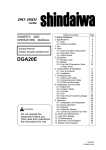
Owners Manual Model DGK25C Sound Attenuated Diesel Generator Set With SimulPhase Technology® WARNING! CALIFORNIA – Proposition 65 Warning Diesel engine exhaust and some of its constituents are known to the State of California to cause cancer, birth defects, and other reproductive harm. 3/9/09 Table of Contents 1. INTRODUCTION......................................................................................................... 4 2. SAFETY INSTRUCTIONS .......................................................................................... 5 3. LABELS.................................................................................................................... 11 3.1 Locations ............................................................................................................................................. 11 3.2 Label Part Numbers ............................................................................................................................ 15 4. SPECIFICATIONS .................................................................................................... 16 5. DESCRIPTION.......................................................................................................... 17 5.1 Layout................................................................................................................................................... 17 5.2 Outside View........................................................................................................................................ 18 5.3 Control Panel....................................................................................................................................... 20 5.4 Generator ............................................................................................................................................. 22 5.4.1 Stator ............................................................................................................................................. 23 5.4.2 Rotor .............................................................................................................................................. 24 5.5 Receptacles and Main Terminals ...................................................................................................... 25 5.6 Drain Plugs and External Fuel Connections .................................................................................... 26 6. EQUIPMENT ............................................................................................................. 27 6.1 Engine Control Circuit ........................................................................................................................ 27 6.2 Monitors and Displays........................................................................................................................ 28 6.3 Meters and Gauges ............................................................................................................................. 30 6.4 Lamps and Lights ............................................................................................................................... 31 6.5 Switches............................................................................................................................................... 31 6.6 Output Circuit Breakers ..................................................................................................................... 33 6.7 Voltage Adjust Rheostat..................................................................................................................... 33 6.8 Voltage Selector Switch ..................................................................................................................... 34 6.9 3 Way Fuel Valve ................................................................................................................................. 35 1 7 LIFTING, TRANSPORTING, AND INSTALLING....................................................... 36 7.1 Lifting ................................................................................................................................................... 36 7.2 Transporting ........................................................................................................................................ 37 7.3 Installing .............................................................................................................................................. 37 8. SIMULTANEOUS THREE PHASE AND DUAL VOLTAGE SINGLE PHASE OUTPUT ....................................................................................................................... 38 9. CONNECTING CABLES .......................................................................................... 39 9.1 Main Terminal Connections 480/277V Position ............................................................................... 39 9.2 Main Terminal Connections 240/139V Position ............................................................................... 40 10. GENERATOR TECHNICAL SPECIFICATIONS..................................................... 41 11. INITIAL STARTUP AND PRE-CHECKS ................................................................ 42 11.1 Checking Engine Oil ......................................................................................................................... 43 11.2 Selecting the Proper Engine Oil ...................................................................................................... 44 11.3 Checking for Leaks ........................................................................................................................... 44 11.4 Checking Engine Coolant ................................................................................................................ 45 11.5 Checking the Fan Belt ...................................................................................................................... 46 11.6 Checking the Fuel Level ................................................................................................................... 47 11.7 Checking the Battery ........................................................................................................................ 47 12. OPERATION ........................................................................................................... 48 12.1 Starting the Generator ...................................................................................................................... 48 12.2 Loading the Generator...................................................................................................................... 49 12.3 Operating the Generator .................................................................................................................. 49 12.4 Stopping the Generator .................................................................................................................... 49 13 GENERAL MAINTENANCE .................................................................................... 50 13.1 Engine Maintenance ......................................................................................................................... 50 13.2 Periodic Maintenance Table............................................................................................................. 51 2 13.3 Changing Oil...................................................................................................................................... 52 13.4 Replacing the Oil Filter ..................................................................................................................... 53 13.5 Cleaning/Replacing the Air Filter Element ..................................................................................... 55 13.6 Cleaning/Replacing the Fuel Filters ................................................................................................ 56 13.7 Replacing the Electric Fuel Pump Filter ......................................................................................... 57 13.8 Draining Water from the Internal Fuel Tank ................................................................................... 57 13.9 Replacing LLC (Long Life Coolant)................................................................................................. 58 14. TROUBLESHOOTING TABLE ............................................................................... 59 15. LONG TERM STORAGE ........................................................................................ 60 3 1. Introduction Thank you for purchasing a Shindaiwa kWiet Power sound attenuated diesel generator. This manual contains important information for the maintenance and safe operation of the Shindaiwa diesel generator model DGK25C. Read and thoroughly understand this manual before operating the generator. This manual should be kept on or near the generator at all times. To maximize the useful life of the generator, follow the recommended periodic maintenance schedule and maintenance checks according to the table on Page 51 of this manual. 4 2. Safety Instructions In this manual, safety items are classified as WARNING and CAUTION. WARNING Indicates a potentially hazardous situation which if not avoided could result in death or serious injury. CAUTION This symbol indicates a potentially hazardous situation which, if not avoided, could result in minor or moderate injury or property damage. Note that CAUTION items could also lead to major accidents under some circumstances if not correctly followed. All items listed in this manual are important for the safe operation of this generator set. Be sure to follow them closely. 5 Warning DANGER OF ELECTRIC SHOCK DO NOT CONTACT THE OUTPUT TERMINALS DURING OPERATION! Contacting the output terminals while the generator set is operating can cause a fatal electric shock. If it is necessary to contact the output terminals (such as for load connections), ensure that the generator set is not operating. DANGER OF EXHAUST GAS POISONING DO NOT OPERATE THIS GENERATOR SET IN AN ENCLOSED AREA! The engine exhaust gas on this generator set contains substances that have been proven to be harmful to human health. Operate this generator set in a well ventilated area only. Using the generator set indoors or in other enclosed places can cause exhaust gas poisoning. DANGER OF INJURY CAUSED BY ROTATING PARTS DO NOT CONTACT ROTATING PARTS DURING EQUIPMENT OPERATION! Stay clear of rotating parts such as the fan, belts or pulleys when the generator set is running. Coming in contact with rotating parts could cause severe bodily injury. Turn off the engine before inspecting or conducting maintenance work on this generator set. 6 DANGER OF ELECTRIC SHOCK, INJURIES OR BURNS PRECAUTIONS FOR MAINTENANCE AND INSPECTIONS! Before conducting inspections or performing maintenance work, remove the key from the ignition switch and place a DO NOT OPERATE sign or similar warning over the ignition switch. Accidental operation of the engine during inspections or maintenance work can cause serious accidents. CAUTION TRANSPORTATION DANGER OF FALLING EQUIPMENT! HANDLE SUSPENDED EQUIPMENT WITH CARE! Do not use twisted or frayed wire cable to lift the generator set. Do not twist lifting chains. Twisted chains can easily break. HANDLE THIS EQUIPMENT ONLY AT THE DESIGNATED LOCATION! The generator unit is designed with a single point lifting hook on the top section. Do not lift the unit at any other point or it may be unbalanced. 7 INSTALLATION DANGER OF INJURIES DO NOT INSTALL THIS EQUIPMENT ON SLOPED OR UNEVEN GROUND! Operating on sloped or uneven ground may cause the generator to move resulting in personal injury. OPERATION DANGER OF FIRE USE EXTREME CAUTION WHEN ADDING FUEL OR OIL! Before adding fuel or oil, stop the engine and make sure there are no open flames in the immediate area. If fuel is spilled or leaks onto hot parts or electrical components, a fire could occur. If fuel or oil is spilled, clean up the area immediately. Close the fuel fill or oil fill cap securely after supplying fuel or oil. MAINTENANCE AND INSPECTION DANGER OF BURNS OR FIRE DISCONNECT THE BATTERY BEFORE INSPECTIONS OR MAINTENANCE! Before conducting inspections or maintenance, disconnect the negative (-) cable from the battery terminal. Conducting inspections or maintenance with the battery cables connected may cause a short circuit resulting in burns or fire. 8 DO NOT ALLOW WATER TO CONTACT ELECTRICAL PARTS! Allowing water to come in contact with electrical components could cause a short circuit resulting in a fire. If water accidentally comes in contact with electrical components immediately deenergize them and use clean dry compressed air to completely dry them out prior to re-energizing. PRECAUTIONS IN HANDLING THE BATTERY HANDLE THE BATTERY CAREFULLY! Batteries generate hydrogen gas and oxygen gas both of which are extremely flammable. Flames or spark producing devices can cause an explosion when brought near the battery. Handle the battery with extreme caution. (1) Wear protective glasses and rubber gloves when conducting maintenance work or inspecting the battery. (2) Do not smoke or generate sparks or flames near the battery. (3) Stop the engine before conducting inspections or maintenance on the battery. (4) Do not short circuit the terminals of the battery. (5) When removing battery cables, disconnect the cable at the negative (-) terminal first. When connecting the cables, connect the positive (+) terminal first. (6) Charge batteries in well ventilated areas only. (7) Connect cables securely to each terminal post. Loose cables may generate sparks and cause an explosion. (8) Before conducting maintenance work on the electrical system remove the negative (-) cable from the battery. 9 HANDLE ELECTROLYTE WITH CARE! Electrolyte contains dilute sulfuric acid. Careless handling of the battery can cause the electrolyte to spill which could result in the loss of eye sight or in burns. Any work that requires the handling of electrolyte must be done under the supervision of someone knowledgeable in safe electrolyte handling procedures. Maintain the electrolyte level in the battery above the minimum level. Electrolyte spills should be immediately flushed with large volumes of clean water. If electrolyte accidentally enters the eye or eyes, immediately wash with large volumes of clean water and consult a physician as soon as possible. If electrolyte is swallowed, rinse the mouth repeatedly with large volumes of water and consult a physician as soon as possible. 10 3. Labels 3.1 Locations Label part number descriptions are listed on page 15. Note: Ensure all labels are undamaged and readable. Immediately replace any damaged or missing labels. New labels are available from your local Shindaiwa distributor or dealer. 11 Note: Ensure all labels are undamaged and readable. Immediately replace any damaged or missing labels. New labels are available from your local Shindaiwa distributor or dealer. 12 Note: Ensure all labels are undamaged and readable. Immediately replace any damaged or missing labels. New labels are available from your local Shindaiwa distributor or dealer. 13 Front Back Top Note: Ensure all labels are undamaged and readable. Immediately replace any damaged or missing labels. New labels are available from your local Shindaiwa distributor or dealer. 14 3.2 Label Part Numbers Reference Number 1 2 3 4 5 6 7 8 9 10 11 12 13 14 15 16 17 18 19 20 21 22 23 24 25 26 27 28 29 30 31 32 33 34 35 Part Number Description Quantity 71260-91310 19406-00115 19406-00089 19420-00057 19404-00025 19407-00078 19407-00079 19407-00080 19407-00081 71260-91320 19401-00212 19401-00214 19401-00405 19401-00211 19401-00216 19401-00404 19401-00401 19401-00400 19402-00210 71260-91330 19407-00055 19402-00295 19402-00306 19502-26000 19401-00390 19406-00111 19402-00288 19401-00412 19401-00411 19401-00409 19401-00410 19406-00118 19402-00215 19401-00372 19401-00431 Name Plate kWiet Power Decal kWiet Power Decal Shindaiwa Decal 25 kVA Decal Decorative Stripe Decorative Stripe Decorative Stripe Decorative Stripe EPA Emissions Label Panel Light Label Voltage Adjust Rheostat Label External Connections and Drains Labels Pilot Lamp Label Ignition Switch Label Receptacle Labels Internal Fuel Tank Level Label Output Connection Diagram Label Lifting Hook Label Hidden Serial Number Plate Auto Start Panel Cover Long Life Coolant Specification Label Main Warning Label kWiet Power Metal Plate Emergency Stop Label Ultra Quiet Technology Label Voltage Selector Switch Caution Label Three Phase Breaker Label Single Phase Breaker Label Voltmeter Selector Switch Label Ammeter Selector Switch Label Specifications Label Ammeter Selector Switch Positions Three Way Valve Label Terminal Cover Instruction Label 1 1 2 2 2 2 1 1 2 1 1 1 1 1 1 1 1 1 1 1 1 1 1 1 1 2 1 1 1 1 1 1 1 1 15 1 4. Specifications DGK25C Specifications Generator Type Rated Output Alternator Amps Voltage-Three phase Voltage-Single phase Single phase-120V Single phase-240V Three phase-208V Three phase-240V Three phase-480V Frequency-regulation Rated Speed Winding Power Factor Insulation class Excitation No. of poles kVA kW V V Hz rpm Type Engine Meters Voltage Regulation Model (Manufacturer) No. of Cylinders (bore x stroke) Continuous Rated Output Rated Speed,60/50Hz Displacement Combustion System Cooling Method Lubricating Method Starting Method Fuel (in./mm) hp rpm cu. in./liters Fuel Consumption gal./liters Lubricating Oil Fuel Tank Capacity Lubricant Volume Cooling Water Volume Starting Motor Capacity Charging Alternator Capacity Battery Capacity Voltage/Frequency/Amperage/Hour gal./liters gal./liters gal./liters V-kW V-A V-AH Revolving Field Brushless Ac Simultaneous 3 Phase120/240V 1 Phase 25 20 208,240,480 120,139,240,277 62.5 x 2 62.5 69 60 30 60/50 ± 5% 1800/1500 Star with Neutral .8 F Self excitation (brushless) 4 Vertical Water Cooled 4cycle Diesel 4LE1 (ISUZU) 4 (3.35 x 3.78/85 x 96) 31 1800/1500* 133/2.179 Swirl Chambered Radiator Forced Lubrication Electric ASTEM No. 2 Diesel 1.57/5.94 per hour @ full load CD class or higher 20.6/78 2.2/8.5 2.2/8.2 12V-2.0kW 12V-20A 12V-80AH 3 Phase ± 1.0% 1 Phase ± 5.0% Lamp indication with Shutdowns Oil Pressure, Water Temperature shutdown Warning Battery Charge Lamp indication 57 x 31 x 45/1440 x 780 in./mm Dimensions (L x W x H) x 1140 Unit lbs./kg 1543/700 Dry weight No Load dB(A) 53 Sound Level Full Load dB(A) 56 *Emissions certified at 1800 rpm only Standard Conditions: Altitude: 3280 ft (1000m) or lower, Temperature: 5-104°F (-15 to +40°C), Humidity: 85% or lower (no condensation) Automatic Voltage Regulator 16 5. Description 5.1 Layout 17 5.2 Outside View Units: Inches 18 Units: Inches 19 5.3 Control Panel Component names are on the following page. Detail Drawing of Warning Indicator High Water Temperature Battery Charge Fault Low Oil Pressure 20 Number 1 2 3 4 5 6 7 8 9 10 11 12 13 14 15 16 17 18 19 20 Description Three Phase Circuit Breaker Single Phase Circuit Breaker Voltmeter Ammeter Frequency Meter Voltmeter Selector Switch Panel Light Voltage Adjust Rheostat Ammeter Selector Switch Warning Indicators Coolant Temperature Gauge Oil Pressure Gauge Fuel Gauge Hour Meter Pre-heating Indicator Ignition Switch Voltage Selector Switch Panel Light Switch Emergency Stop Switch Pilot Lamp 21 5.4 Generator The generator is designed with a rigid cast stator for superior quality and exceptional durability. It includes a powerful damper winding that minimizes wave form distortion and maximizes motor starting capability. 22 5.4.1 Stator The stator is the external stationary portion of the generator that actually provides the electricity for distribution to the load. It is composed of several individual coils of copper wire distributed and wound such that the magnetic field associated with the rotor passes over and around the coils and in turn produces an electric potential (voltage) that is used as the supply voltage to the load. This stator also houses the stationary coils used as the exciter stator for the generator field exciter. The stator is bolted directly to the flywheel housing of the engine. The end bracket and end cover are bolted directly to the end of the stator opposite to where the stator is bolted to the flywheel housing. 23 5.4.2 Rotor The rotor is the portion of the generator bolted directly to the crankshaft of the engine so that it will rotate at the same speed that the engine crankshaft is rotating. The opposite end of the rotor is supported by the generator end bracket using a single ball bearing. The rotor has the field coils attached to it. The amount of current through the field coils determines the strength of the rotating magnetic field being used to generate a potential in the stator and therefore determines the output voltage of the generator. Field coil current is regulated by the exciter output, which is in turn regulated by the automatic voltage regulator. The rotating portion of the exciter is also mounted on the rotor. 24 5.5 Receptacles and Main Terminals Note: All duplex receptacles are GFCI circuit breaker protected and are rated at 20 amps. All twist lock receptacles are rated at 50 amps and are also circuit breaker protected. L1 L2 L3 N/G U Single Phase 120V Circuit Breaker Single Phase 120V Receptacle W N/G Single Phase 240/120V Circuit Breaker Single Phase 120V Receptacle Single Phase 240/120V Receptacles 25 5.6 Drain Plugs and External Fuel Connections 26 6. Equipment 6.1 Engine Control Circuit Automatic Pre-Heating System When the ignition switch is placed in the ON position the glow plugs and glow indicator are energized. Pre-heating time is based on coolant temperature. The glow time relay (QOS) detects the coolant temperature and if the temperature is between 5°F and 68°F pre-heating time is approximately 5 seconds. If the temperature is above 68°F the pre-heating time is approximately 2 seconds. Control Power When the ignition switch is placed in the RUN/PREHEAT position control power is supplied from the battery. The stop solenoid is energized and allows fuel flow to the injection pump. Starting When the ignition switch is placed in the START position, the starter motor is energized and cranks the engine to get the engine started. After the engine starts release the switch, and let it automatically return to the ON position. Stopping When the ignition switch is set to the STOP position, the stop solenoid is de-energized and shuts off fuel flow to the injection pump. Protection Over Current- When output amperage exceeds the rated current, the circuit breaker trips and the breaker handle will be positioned between ON and OFF. Move the handle to the OFF position to reset the breaker prior to re-closing it. Low Oil Pressure- When lubricating oil pressure drops to 14 psi or less the emergency timer shuts down the engine. High Coolant Temperature- When coolant temperature exceeds 230°F the emergency timer shuts down the engine. Charging fault- If the battery charging system malfunctions, the charge indicator light will turn on but the engine will not shut down. 27 6.2 Monitors and Displays The DGK25C diesel generator is equipped with monitoring functions for coolant temperature, oil pressure and battery charge condition. Under normal operating conditions these monitoring lamps will illuminate momentarily when the engine is first started but will go out shortly thereafter. If an abnormal condition is detected in the coolant temperature or oil pressure, the corresponding monitor lamp will flash and the automatic shutdown will be activated shutting down the engine. The battery charge light will cause only the light to flash. If an automatic shutdown is activated, check for and correct the cause of the shutdown prior to trying to restart the generator set. Coolant Temperature Monitoring Indicator Warning Injuries To avoid injuries by unintentional contact with the fan and/or fan belts, close and lock all doors while operating this equipment. Burns To avoid sustaining burns from hot vapor, do not open the radiator cap while operating or immediately after stopping the equipment. Due to extremely high temperatures, do not come in contact with the engine and/or muffler while operating or immediately after stopping this equipment. If the coolant temperature reaches 230°F during operation, the coolant temperature monitoring lamp will flash and automatically shut down the engine. If this occurs, check the coolant reservoir tank level, and if low, replenish the coolant in the reservoir as needed with a 50:50 mix of water and Long Life Coolant (GM Spec 6277M or equivalent). NEVER ADD COOLANT TO THE RADIATOR WHEN THE ENGINE IS HOT!! After the engine cools down check for any coolant leaks and repair if needed. CAUTION If the coolant level is too low the temperature sensor cannot detect the coolant temperature. Always check the coolant level in the radiator and coolant reservoir tank prior to operating this equipment. 28 Engine Oil Monitoring Indicator If the engine oil pressure drops below 14 psi during operation, the oil pressure monitoring lamp will flash, and the automatic shutdown will activate. If this occurs, check the engine oil level, and fill to the maximum level if needed. WARNING Injuries To avoid injuries by unintentional contact with moving parts such as the cooling fan and/or belts, close and lock all doors while operating this equipment. WARNING Burns Due to extremely high temperatures, do not come in contact with the engine and/or muffler while operating or immediately after stopping this equipment. When checking or changing the engine oil, always stop the engine and allow sufficient time for the engine to cool down. Opening the oil filler cap during operation can cause injury due to hot oil. CAUTION The oil pressure sensor cannot detect engine oil degradation due to extended use. Oil change intervals listed under the Periodic Maintenance Table must be strictly adhered to. Battery Charge Monitoring Indicator Insufficient battery charging during operation will cause the battery charge light to flash. If this occurs, check the condition and tightness of the fan belt and replace or tighten if necessary. This light is an indicator that the charging system is not working properly and possibly the battery charging alternator has insufficient output to keep the battery charged. Further testing may be required by a skilled technician. CAUTION If the belt needs to be replaced refer to the Engine Workshop Manual. The battery charge light cannot detect the degradation of battery life or the battery fluid level. 29 6.3 Meters and Gauges Hour Meter The hour meter keeps track of the total run time of the engine. This meter should be used to schedule preventive maintenance. Note: The hour meter will continue to operate as long as the ignition switch is in the on position regardless if the engine is running or not. Water Temperature Gauge The water temperature gauge displays the temperature of the engine coolant. Normal operating temperature will vary between 176°F to 203°F depending on load and ambient temperature. Oil Pressure Gauge The oil pressure gauge indicates the pressure of the engine oil. Normal operating pressures may vary depending on conditions but should display between 40 psi and 60 psi. In colder climates the oil pressure gauge may read higher at start up due to the viscosity of the engine oil. Allow the engine to warm up until a normal reading is obtained prior to loading the generator. Fuel Gauge The fuel gauge indicates the level of fuel in the internal tank only. If an external fuel tank is being used the fuel gauge will not indicate the fuel level in the external tank. Volt Meter The volt meter displays the phase to phase output voltage of the generator. The displayed phase voltage will be dependant on the position of the voltmeter selector switch. Ammeter The ammeter displays the electrical output current from the generator. The displayed phase current output will be dependant on the position of the ammeter selector switch. Frequency Meter The frequency meter will display the frequency of the generated power. 30 6.4 Lamps and Lights Glow Lamp When the ignition switch is turned to the run/preheat position the glow lamp will illuminate. The glow lamp will stay lit until the preheat cycle is completed. This indicates that the engine is now ready to start. The preheat cycle time will depend on ambient and engine temperatures and may vary from 1- 5 seconds. Pilot Lamp The pilot lamp indicates whether or not power is being produced when the engine is running. When the pilot light is illuminated the engine is running and there is power being produced. When the pilot lamp is not illuminated and the engine is running then there is no power being produced and it indicates a problem with the generator system. Panel Light The panel light is used to illuminate the generator control panel. This light can be turned on and off with the toggle switch that is located to the right of the panel light. The panel light will operate only when the ignition switch is in the ON position. This prevents discharging the battery if the switch is left on and the generator is not running. 6.5 Switches Ignition Switch The ignition switch is a three position switch used for starting, stopping and preheating the engine. Positions: Stop: When the switch is placed in this position all power will be turned off. The switch must be in this position to remove the key. Run/Preheat: The switch must be in this position during operation. When the switch is placed in this position the engine preheat cycle commences. This switch position is also used to remove air from the fuel system. Note: Do not leave the switch in this position if the engine is not running because the hour meter will continue to operate until the battery is completely discharged. Start: This position energizes the starter motor which cranks the engine to get it started. The switch will automatically return to the run/preheat position when the key is released. Note: Do not hold the switch in this position after the engine starts or starter damage may occur. 31 Emergency Stop Switch The emergency stop switch is located directly to the left of the ignition switch. It is a red button type switch that when pushed in will cause the engine to immediately stop. It will remain pushed in until manually reset by pushing it again. Voltmeter Selector Switch The voltmeter selector switch is a 5 position switch located on the control panel to the left of the voltmeter. The voltmeter selector switch selects which phase voltage is displayed on the voltmeter. Positions: Off: There are two off positions on the voltmeter selector switch. One at the full clockwise position and one at the full counter-clockwise position of the switch. In either off position the voltmeter will not display any voltage. L1-L2: In the L1-L2 position the voltmeter will display the phase voltage between L1 and L2. L2-L3: In the L2-L3 position the voltmeter will display the phase voltage between L2 and L3. L3-L1 / U-W: In the L3-L1 / U-W position the voltmeter will display the phase voltage between L3 and L1 and U and W phase voltage. Ammeter Selector Switch The ammeter selector switch is a 5 position switch located on the control panel to the left of the ammeter. The ammeter selector switch selects which phase current is displayed on the ammeter. Positions: Off: There are two off positions on the ammeter selector switch. One at the full clockwise position and one at the full counter-clockwise position of the switch. In either off position the ammeter will not display any amps. L1 / U: In the L1 / U position the ammeter will display the total phase current for L1 plus the phase current of U. L2: In the L2 position the ammeter will display the phase current for L2. L3 / W:In the L3 / W position the ammeter will display the total phase current for L3 plus the phase current of W. 32 6.6 Output Circuit Breakers The DGK25C has two main output circuit breakers located on the left side of the control panel that are used to connect the generator output to the main terminals. The three phase circuit breaker is for connecting and disconnecting the load on terminals L1, L2 and L3. The single phase circuit breaker is for connecting and disconnecting the load on the U and W terminals. Turning the circuit breaker on will enable power to flow to the main terminals. Turning the circuit breaker off will disconnect power to the main terminals. These breakers will both trip in the event of an overload condition on the generator or if the terminal box cover is opened while the engine is running. 6.7 Voltage Adjust Rheostat The voltage adjust rheostat is used to adjust the generated output voltage of the generator. Turning the voltage adjust rheostat clockwise will increase the output voltage and turning the voltage adjust rheostat counter-clockwise will decrease the voltage. The adjustable range available for voltage adjustment is plus 5% and minus 15%. 33 6.8 Voltage Selector Switch Voltage Selector Switch The voltage selector switch is a 2 position lockable switch located on the right side of the control panel. This switch provides a quick and convenient method of changing the generator output voltage. Note: This switch should NEVER be changed while the generator is running or serious damage may occur! Positions: 3 Phase 480/277: The 3 phase 480/277 position gives an output from the generator of 480 volts 3 phase and 277 volts single phase at the 3 phase terminal board and 120 or 240 volts at the single phase terminal board. 3 Phase 240/139: The 3 phase 240/139 position gives the output from the generator of 240 volts 3 phase and 139 volts single phase at the 3 phase terminal board and 120 or 240 volts at the single phase terminal board. Voltage Selector Switch 34 6.9 3 Way Fuel Valve The 3 way fuel valve is located inside the enclosure on the right side of the engine. This valve provides a quick and convenient method of attaching an external fuel tank for supplying fuel to the engine. The 3 way valve comes from the factory in the A position which provides fuel from the internal fuel tank to the engine. Positions: Position A: When using an external fuel tank for the fuel supply to the engine, remove the 3/8” pipe plugs, connect the fuel lines from the external tank to the appropriate inlet and return port fittings and then set the 3 way valve to position A. Note: The internal fuel tank will not supply fuel to the engine when in position A. Position B: When using the internal tank for the fuel supply to the engine, set the 3 way valve to position B. In position B the fuel for the engine is supplied by the internal fuel tank. Note: Always ensure external fuel ports are plugged with the supplied 3/8” pipe plug fittings when the 3 way valve is in position B. CAUTION Always stop the engine prior to performing any work on the fuel system or fuel lines. Immediately clean up any fuel leakage. Position A Position B 35 7 Lifting, Transporting, and Installing 7.1 Lifting WARNING The lifting hook is designed to lift only the weight of the generator. Do not lift any additional added weight such as fuel tanks and/or trailers with the lifting hook. CAUTION Use only the installed lifting hook for lifting the equipment. Do not use the tie down posts for lifting as they are not designed to hold the weight of the equipment. Always use the installed lifting hook whenever lifting this equipment. Note: The lifting hook is designed to lift only the weight of the generator. Do not lift any additional weight such as a fuel tank and/or trailer with the lifting hook. Do not lift with the tie downs. 36 7.2 Transporting WARNING Always use extreme caution when loading, unloading or transporting this equipment. Failure to do so may result in personal injury or death and/or damage to the equipment. When transporting this equipment, ensure that the equipment is properly secured using the tie down posts. 7.3 Installing WARNING Suffocation from exhaust gases: Exhaust fumes from the engine contain many elements that have been proven to be harmful to humans. Do not operate this equipment in poorly ventilated areas such as inside buildings or in tunnels. Do not direct the exhaust fumes towards pedestrians or buildings. CAUTION Fire: Operate this equipment only on flat surfaces and at least 3 feet away from any objects, such as walls, as overheating may occur due to lack of air flow. Temperatures around the muffler and exhaust system can get extremely hot. Keep all flammable items away from this equipment during and immediately after operation. Always place this equipment on a hard, flat and level surface. Keep the equipment at least 3 feet away from any obstruction that might restrict the air flow to the exhaust or radiator cooling air. Failure to do so may result in a reduction in engine performance, overheating and/or damage to the equipment. Operating the equipment in dusty or other harsh environments may result in a clogged radiator or air filter element and may result in overheating. Be sure to check the radiator, air filter element, fuel filter, and electrical terminal blocks on a daily basis and in some cases more often when operating it in a harsh environment. 37 8. Simultaneous Three Phase and Dual Voltage Single Phase Output 100 (%) 75 50 25 0 15 (kVA) 11.25 3.75 240/139V 0 7.5 7.5 (kVA) 5.63 3.75 1.88 480/277V 0 Dual Single Phase Output When using three phase and simultaneous dual voltage single phase output the load must be properly balanced so as not to overload the generator. The charts below show that when the three phase load is increased the available single phase output is decreased and vice versa. Use the ammeter selector switch to check the amperage flow in all settings. The ammeter should never exceed 60 amps (top scale) in any one position. When the ammeter selector switch is in the U-L1 position the ammeter will display the combined amperage of both single phase line U and three phase line L1. In the W-L3 position the ammeter will display the combination of single phase line W and three phase line L3. For example, with the voltage selector switch in the 240/139V position and the dual single phase load is 7.5 kVA (30 amps) then the available three phase output will be 12.5 kVA (30 amps). 0 25 50 75 100 (%) 0 6.2 12. 18.7 25 (kVA) 3 Phase Output 38 9. Connecting Cables 9.1 Main Terminal Connections 480/277V Position WARNING Electric Shock Before connecting or disconnecting the load cables from the output terminals, always turn the output circuit breakers to the OFF position, stop the engine, and remove the ignition key. The person performing the connection or disconnection should always have possession of the key. 480 V 480 V 277 V 240 V 480 V 120 V 120 V 277 V 277 V 39 9.2 Main Terminal Connections 240/139V Position WARNING Electric Shock Before connecting or disconnecting the load cables from the output terminal, always turn the output circuit breakers to the OFF position, stop the engine, and remove the ignition key. The person performing the connection or disconnection should always have possession of the key. 240 V 240 V 240 V 139 V 240 V 120 V 120 V 139 V 139 V 40 10. Generator Technical Specifications Items Insulation Armature Winding Exciter Field Pre-Heating Time High Idling Speed Lubricating Oil Pressure Coolant Temperature Engine Speed Droop Voltage Regulation Low Oil Pressure Protective Devices High Water Temperature Transient Deviation Steady State Deviation Transient Deviation Steady State Deviation Working Pressure Part Number (Isuzu) Working Temperature Part Number (Isuzu) 41 Reference Value 3 MΩ or more 3 MΩ or more 5 seconds: Coolant temperature between 5°F and 68°F 2 seconds: Coolant temperature is greater than 68°F 50HZ: up to 1575 rpm 60 HZ: up to 1890 rpm 14.5 to 71 psi 158°F to 218°F (70°C to 100°C) Notes DC 500V Meg Ohm Tester Automatic pre-heating system Within 5% Within 10% Full Load to No Load Within 5% Within 20% Full Load to No Load Within ±1% 14 psi (1.0±0.2 kgf/cm2) 982720-0690 230°±4°F (110°±2°C) 894132-3310 Closed When Activated Closed When Activated 11. Initial Startup and Pre-Checks WARNING Electrical Shock Before performing any equipment checks or maintenance, stop the engine, and remove the engine key. The person performing the equipment checks or maintenance should always have possession of the key. CAUTION Burns To avoid sustaining burns from hot vapors, do not open the radiator cap while operating or immediately after stopping this equipment Due to extremely high temperatures, do not touch the engine or exhaust system while operating or immediately after stopping this equipment. When checking or changing the engine oil, stop the engine, and wait until the engine cools down before removing the engine oil level dipstick or opening the oil fill cap. Removing the engine oil level dipstick or opening the oil fill cap during or immediately after operation may cause injury due to hot oil. Fire Immediately wipe up any diesel fuel or engine oil that is spilled. Do not use this equipment if there are any leaks. If leaks are found, repair the leak before further use. 42 11.1 Checking Engine Oil (Also refer to the accompanying Engine Instruction Manual) When checking the engine oil, be sure to keep the equipment level and insert the dipstick fully. Prior to starting the engine, make sure to fill the engine oil to the MAX line through the oil filler opening. CAUTION If the equipment is not level, you cannot obtain an accurate oil level reading. Do not overfill the engine with oil as this may result in damage to the engine. 1. Remove the dipstick from the crankcase and wipe it clean with a clean cloth. 2. Reinsert the dipstick fully and gently remove it again. 3. Check the oil level on the dipstick. The level must be between the Max level mark and the Min level mark. 4. If the level is above the Max mark, drain oil out until the level is between the Max and Min marks. 5. If the level is at or below the Min level mark, add oil until the level is between the Max and Min marks. Dipstick MAX MIN OK Low 43 High 11.2 Selecting the Proper Engine Oil Use engine oil specifically designed for diesel engines. Use the chart below to determine the proper viscosity of oil to use for the anticipated ambient temperature the equipment will be operated in. Oil Viscosity and Temperature Temperature °F -22° 5° 32° 60° 77° 86° SAE10W-30 SAE30W SAE10W SAE20/20W SAE40W SAE15W-40/20W-40 CAUTION Use only API class CD grade or higher engine oil. 11.3 Checking for Leaks Prior to starting the engine, make sure a complete and thorough inspection is performed to check for any leaks. CAUTION Do not use this equipment if a leak is detected. Repair the leak before further use. Always check closely around hoses and fittings for signs of leaks. 44 11.4 Checking Engine Coolant (Also refer to the accompanying Engine Instruction Manual) WARNING Injuries Before performing any equipment checks or maintenance, stop the engine, and remove the engine key. The person performing the equipment checks or maintenance should always have possession of the key. CAUTION Burns To avoid sustaining burns from hot vapors, do not open the radiator cap while operating or immediately after stopping this equipment. Due to extremely high temperatures, do not touch the engine or exhaust system while operating or immediately after stopping this equipment. When checking or changing the engine oil, stop the engine, and wait until the engine cools down before removing the engine oil level dipstick or opening the oil fill cap. Removing the engine oil level dipstick or opening the oil fill cap during or immediately after operation may cause injury due to hot oil. Fire Immediately wipe up any diesel fuel or engine oil that is spilled. Do not use this equipment if there are any leaks. If leaks are found, repair the leak before further use. Procedure for Checking Radiator Coolant Level: 1. Remove the radiator access plate on top of the enclosure. 2. Loosen the thumb screw for the radiator cap access door. 3. Remove the radiator cap and check the level of the coolant. The coolant level should be up to the filler neck. If the level is low, add a 50:50 mix of Long Life Coolant (GM SPEC 6277M or equivalent) until the level is at the filler neck. 4. Reinstall the radiator cap, install the radiator access door and reinstall the radiator access plate. Procedure for Checking the Coolant Reservoir Level: 1. Open the enclosure door to gain access to the reservoir. 2. The coolant level should be between the Min and Max line. If the coolant level is low, add a 50:50 mix of Long Life Coolant (GM SPEC 6277M or equivalent) and water until the level is between the Min and Max line. CAUTION Always use potable water when mixing the coolant. Coolant is combustible. Do not spill any coolant on the exhaust or hot engine parts. 45 11.5 Checking the Fan Belt (Also refer to the accompanying Engine Instruction Manual) WARNING Injuries Before performing any equipment checks or maintenance, stop the engine, and remove the engine key. The person performing the equipment checks or maintenance should always have possession of the key. To avoid injuries by unintentional contact with the cooling fan or fan belt, close and lock all doors while operating this equipment. CAUTION Burns Due to extremely high temperatures, do not come in contact with the engine and/or muffler while operating or immediately after stopping this equipment. Procedure for Checking the Fan Belt and Fan Belt Tension: 1. Gain access to the alternator side of the engine. 2. The fan belt should have ¼ to ½ inch of slack when applying finger pressure on the belt between the alternator and water pump pulley. 3. Check the condition of the belt. If the belt is cracked or damaged replace the fan belt before operating this equipment. The procedure for replacing the fan belt can be found in the accompanying Engine Instruction Manual. 4. If the belt is loose refer to the Engine Instruction Manual for the tightening procedure. 46 11.6 Checking the Fuel Level Prior to starting the engine, check the fuel level in the tank that is supplying fuel to the engine. The fuel gauge on the control panel will display only the fuel level for the internal fuel tank. Always use the fuel strainer installed in the fuel fill pipe when refueling. CAUTION Fire Immediately wipe up any diesel fuel or engine oil that is spilled. Do not use this equipment if there are any leaks. If a leak is found, repair the leak before further use. Fill the fuel tank slightly below the Full mark to allow for expansion of the fuel. CAUTION The fuel injector pump, injectors and other parts of the fuel system and engine can be damaged if any fuel or fuel additives are used other than those specifically recommended by the engine manufacturer. Refer to the Engine Instruction Manual for the recommended fuels. 11.7 Checking the Battery Procedure: 1. Check the battery fluid level. If the level is at or near the lower level mark, fill with distilled water to the upper level mark. 2. Make sure the battery terminal connections are tight and free of corrosion. 3. Make sure the battery is securely mounted with the supplied bracket. CAUTION Injury Battery fluid contains diluted sulfuric acid. Avoid contact with eyes, skin or clothing. If contact with the acid does occur, especially with the eyes, immediately flush with large volumes of water and contact a physician immediately. 47 12. Operation 12.1 Starting the Generator WARNING Suffocation from exhaust gases: Exhaust fumes from the engine contain many elements that have been proven to be harmful to humans. Do not operate this equipment in poorly ventilated areas such as inside buildings or in tunnels. Do not direct the exhaust fumes towards pedestrians or buildings. CAUTION Injuries Always place the equipment on a flat, hard, level surface and at least 3 feet way from obstructions. Due to extremely high temperatures, do not touch the engine or exhaust system while operating or immediately after stopping this equipment. Before starting this equipment, turn the output circuit breakers to the OFF position. Fire Immediately wipe up any diesel fuel or engine oil that is spilled. Do not use this equipment if there are any leaks. If leaks are found, repair the leak before further use. Procedure: 1. Turn the three phase and single phase generator output circuit breakers to the OFF position. 2. If this is the first time starting the engine, refer to After Long Term Storage Starting Procedure on Page 60 of this manual. 3. Set the Voltage Selector switch to the desired three phase output voltage. 4. Turn the ignition key to the Preheat/Run position until the Glow Lamp Indicator turns off. 5. Turn the ignition key to the Start position and release it as soon as the engine starts. Note: Do not hold the key in the Start position for more than 10 seconds or damage to the starter system may occur. If the engine does not start, wait at least 30 seconds before attempting to start it again. 6. Once the engine starts, check to make sure all monitoring lamps are not lit. 7. Allow the engine to run, with no load, for at least 10 minutes prior to closing the main circuit breakers. 48 WARNING Electric Shock: Before connecting or disconnecting the load cables from the output terminals, always turn the output circuit breakers to the OFF position, stop the engine, and remove the ignition key. The person performing the connection or disconnection should always have possession of the key. 12.2 Loading the Generator Procedure: 1. Check that the output voltage is set for the desired voltage and adjust if necessary. 2. Close the generator output circuit breakers. 12.3 Operating the Generator Procedure: 1. 2. 3. 4. 5. Make sure all monitoring lights remain off. Check and make sure all gauges and meters are working properly. Check for any unusual vibration or noise. Check for any unusual color from the exhaust. NEVER change the voltage selector switch while the generator is running. 6. If the output circuit breakers trip OFF, make the necessary corrections or repairs (or decrease the load) prior to resetting the breaker. 7. If a fault shuts the engine down, correct the fault before resuming operation. 12.4 Stopping the Generator Procedure: 1. 2. 3. 4. Turn the load circuit breakers to the OFF position. Turn the generator output circuit breakers to the OFF position. Allow the engine to run unloaded for at least 3 minutes. Turn the ignition key to the Stop position. CAUTION The electric fuel pump continues to operate whenever the key is in the run position even if the engine is not running. 49 13 General Maintenance 13.1 Engine Maintenance WARNING Electrical Shock Before performing any equipment checks or maintenance, stop the engine, and remove the ignition key. The person performing the equipment checks or maintenance should always have possession of the key. CAUTION Burns To avoid sustaining burns from hot vapors, do not open the radiator cap while operating or immediately after stopping this equipment Due to extremely high temperatures, do not touch the engine or exhaust system while operating or immediately after stopping this equipment. When checking or changing the engine oil, stop the engine, and wait until the engine cools down. Removing the engine oil level indicator or opening the oil fill cap during or immediately after operation may cause injury due to hot oil. Fire Immediately wipe up any diesel fuel or engine oil that is spilled. Do not use this equipment if there are any leaks. If a leak is found, repair the leak before further use. To maximize the useful life of this generator, follow the recommended periodic maintenance schedule and maintenance checks according to the following table. The hour meter should be used as a guide to schedule the maintenance and checks. 50 13.2 Periodic Maintenance Table Description Engine Engine Oil (Check/Add) Engine Oil (Replace) (1st time at 50 Hrs) Oil Filter (Replace) (1st time at 50 Hrs) Coolant (Check/Add) Coolant (Change/Radiator Flush) Pre-Filter Bowl (Clean/Drain Water) Main and Pre-Fuel Filter (Replace) Fuel Tank (Drain Water) Fuel Tank (Clean) Fuel Hoses (Replace) Check for Leaks (Fuel/Oil/Coolant) Air Cleaner Element (Inspect/Clean) Air Cleaner Element (Replace) Battery Fluid (Level/Specific Gravity Check) Fan Belt Tension (Check) Wiring and Connections (Check) Inspect and Clean All Terminal Boards Radiator (Clean) Fuel Injector Nozzle Tip (Check) Exhaust Color (Check) Valve Clearance (Check/Adjust) Compression (Check) Fuel Injection Nozzle Pressure (Check) Fuel Injection Timing (Check) Generator Indicators, Gauges, Alarms (Check) Daily 50 Hrs 200 Hrs О О О 400 Hrs 500 Hrs 1000 Hrs О О О О О О О О О О О О О О О О О О О О О О О О 51 13.3 Changing Oil Frequency: First Time 50 Hours Thereafter Every 200 Hours Procedure: 1. Clean the area around the oil fill cap to prevent the entry of foreign material. 2. Remove the oil fill cap. 3. Remove the engine oil drain plug. Turn the ball valve just inside the enclosure counterclockwise to open the valve and allow the oil to drain completely. 4. Turn the ball valve clockwise to shut the valve and then reinstall the oil drain plug and tighten. 5. Fill with new oil through the oil filler opening until the oil level is at the max line on the dipstick (approximately 2 gallons). 6. Reinstall the oil filler cap and tighten by hand. 7. Start the engine and check for any leaks. 8. Stop the engine, wait 20 minutes, and then recheck the engine oil level, with the dipstick. If necessary, add additional oil to bring the level to the max line on the dipstick. Dipstick MAX MIN OK Low 52 High Oil Filter Dip Stick Oil Drain Valve Oil Filler Main Fuel filter Oil Drain Plug Oil Drain Plug CAUTION Use only engine oil designated API, CD grade or higher. Refer to Engine Instruction Manual for recommended oil viscosity. 13.4 Replacing the Oil Filter Frequency: First Time 50 Hours Thereafter Every 400 Hours Procedure: 1. Clean the area around the oil filter and oil filler cap to prevent entry of foreign material. 2. Remove the oil fill cap. 3. Remove the engine oil drain plug and turn the ball valve just inside the enclosure counterclockwise to allow the oil to drain completely. 4. Turn the ball valve clockwise to shut the valve and then reinstall the oil drain plug and tighten. 5. Using an oil filter wrench, loosen and remove the oil filter. (Continued on the next page) 53 6. Lightly coat the rubber gasket on the new oil filter with new engine oil. 7. Install the new oil filter until the rubber gasket makes contact with the sealing face. 8. Use an oil filter wrench to tighten the oil filter an additional ¾ turn. 9. Fill with new oil, through the oil filler opening, until the oil level is at the max line on the dipstick (approximately 2 gallons). 10. Reinstall the oil filler cap and tighten by hand. Gasket Dipstick MAX MIN OK Low High CAUTION Use only engine oil designated API, CD grade or higher. Refer to Engine Instruction Manual for recommended oil viscosity. 54 13.5 Cleaning/Replacing the Air Filter Element Frequency: Inspect/Clean Daily Replace Every 500 Hours Procedure: 1. 2. 3. 4. 5. 6. 7. 8. Unscrew the retaining ring wing nut for the air filter housing end. Remove the air filter housing end. Remove the wing nut. Remove air filter element and clean or replace the element. Reinstall the air filter element and wing nut. Install the air filter housing end retaining ring. Tighten the retaining ring wing nut. Push the reset button on the indicator upon replacing or cleaning the air filter. Indicator Air Cleaner Air Cleaner Cap Screw Reset button Indicator (Red signal) CAUTION In dusty or other harsh environments, increase the frequency of cleaning or replacing of filters. 55 13.6 Cleaning/Replacing the Fuel Filters Frequency: Pre-Fuel Filter/Clean Daily Fuel Tank/Drain Water Every 200 Hours Main Fuel Filter/Replace Every 500 Hours Procedure for the Pre-Fuel Filter: 1. Turn the fuel shut off valve on the top of the pre-fuel filter to the CLOSED position as shown in the below diagram. 2. Unscrew the ring nut by turning counterclockwise and remove the retaining cup and pre-fuel filter element. 3. Remove any debris and/or water from inside the bowl, and then clean the prefilter element using compressed air (or replace if necessary). Note: If replacing the pre-filter element, replace the o-ring as well. 4. Reassemble and turn the butterfly valve to the OPEN position as shown in the diagram below. 5. Without starting the engine, place the ignition switch in Run/Preheat position for at least 30 seconds to bleed any air from the fuel system. Procedure for Replacing the Main Fuel Filter: 1. Using a filter wrench, unscrew the main fuel filter by rotating it counterclockwise. 2. Clean the sealing surface on the upper cover. 3. Apply a light film of new oil on the fuel filter seal and thread the new fuel filter on until the seal makes contact with the sealing surface. Using a filter wrench, turn the additional 2/3 of a turn to seat the filter. 4. Without starting the engine, place the ignition switch in Run/Preheat position for at least 30 seconds to bleed any air from the fuel system. 5. Start engine and check for leaks. Pre Fuel Filter Shut off Valve Closed Ring Nut Pre-Fuel Filter Open Filter Spring Spring Seat 56 Main Fuel Filter 13.7 Replacing the Electric Fuel Pump Filter Frequency: Replace Every 1000 Hours Procedure: 1. 2. 3. 4. Turn the bottom cover of the pump counterclockwise to remove the end. Remove the electric fuel pump filter and seals Install the new filter and seals in the reverse order. Without starting the engine, place the ignition switch in Run/Preheat position for at least 30 seconds to bleed any air from the fuel system. 5. Start engine and check for leaks. Electric Fuel Pump Filter 13.8 Draining Water from the Internal Fuel Tank Frequency: Drain Every 200 Hours Procedure: 1. Remove the fuel drain plug. 2. Turn the ball valve located just inside the enclosure counterclockwise to open the valve and allow any water in the bottom of the tank to drain. 3. After completely draining any water, turn the ball valve clockwise to shut the valve and then reinstall the plug. 4. Start engine and check for leaks. Fuel Drain Lever 57 Fuel Drain Plug 13.9 Replacing LLC (Long Life Coolant) Frequency: Replace LLC Every 1000 Hours Procedure: 1. 2. 3. 4. Remove the radiator plate located on the top of the enclosure. Remove the radiator cap cover. Remove the radiator cap and check seal (replace the seal if it is damaged). Loosen the radiator drain valve and drain plug on engine side and drain the coolant completely. 5. Tighten the radiator drain valve. 6. Drain the coolant reservoir. 7. Install a mixture of 50:50 LLC and water into the reservoir to the full mark. 8. To avoid trapping any air, slowly fill the radiator with a mixture of 50:50 LLC and water. 9. Reinstall the radiator cap tightly. 10. Close the radiator cap cover and install the radiator top plate. 11. Check for leaks. 12. Start the engine, let it warm up, and check for leaks. 13. Turn off the engine and let it cool down. 14. Check the coolant reservoir and replenish if needed. Note: Use GM SPEC 6277M or equivalent long life coolant only. Do not mix different brands of coolant. 58 14. Troubleshooting Table Problem Starter motor will not turn over. Starter Motor turns over but the engine will not start. Engine starts but immediately stalls. Circuit breaker cannot be placed in the on position. Excessive black or white smoke is coming out of the exhaust. Cause 1. Weak Battery 2. Dead Battery 1. No Fuel 2. Water or contaminants in the fuel. 1. Low oil pressure. 2. High coolant temperature. 3. Air in the fuel system. 1. Circuit breaker has not been turned to the off position prior to turning it to on. 2. Overload 3. Terminal board cover is not completely closed. 1. Excessive Load 59 Corrective Measure 1. Recharge the battery. 2. Recharge or replace the battery. 1. Add fuel to the fuel tank. 2. Drain any water from the pre-fuel filter and/or internal fuel tank. 3. Clean the fuel tank and fuel filter. 1. Check the oil and add oil if necessary. 2. Check coolant and add if necessary. 3. Bleed the air out of the fuel system. 1. Turn the breaker to the off position and then place it in the on position. 2. Decrease the load. 3. Close and secure the terminal board cover. 1. Reduce the load on the generator. 15. Long Term Storage (If the generator will not be used for more than 2 months perform the following procedure.) Procedure for Long Term Storage: 1. 2. 3. 4. Remove the battery. Change the engine oil. Drain the fuel from the fuel tank and filters. Clean all parts, cover the generator, and store in an area free of dust or humidity. After Long Term Storage Starting Procedure: 1. Install the battery, check the electrolyte level and charge the battery if necessary. 2. Check all fluid levels as described in “Initial Start Up and Pre-Checks” beginning on page 32 of this manual and add fluid or fluids as necessary. 3. Disconnect the Shut down Solenoid connector to keep the engine from starting. 4. Crank the engine for 10 seconds. Wait 30 seconds and then crank the engine for an additional 10 seconds. Note: This helps prime the engine oil system. 5. Reconnect the Shut down Solenoid connector. 6. Start the engine. Note: If the engine does not start within 10 seconds wait 30 seconds before attempting to start the engine again. 7. Allow the engine to run with no load for at least 10 minutes. Note: The “After Long Term Storage Starting Procedure” should also be performed before the initial starting of a new generator. Shut Down Solenoid Connector Shut Down Solenoid 60 Shindaiwa Incorporated 11975 SW Herman Road Tualatin, OR 97062 Phone 503 692-3070 Fax 503 692-6696 www.kwietpower.com 3/9/09 Part No. 80350 Manufactured by Shindaiwa Corporation Hiroshima, Japan