1
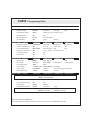
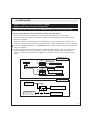
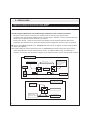
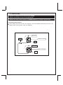
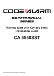
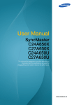
CA 650 Installation Instructions
PROFESSIONAL INSTALLATION STRONGLY RECOMMENDED
Installation Precautions:
Roll down window to avoid locking keys in vehicle
during installation
Avoid mounting components or routing wires near
hot surfaces
Avoid mounting components or routing wires near
moving parts
Tape or loom wires under hood for protection and
appearance
Use grommets when routing wires through metal
surfaces
Use a Digital Multi Meter for testing and verifying
circuits. DO NOT USE A TEST LIGHT, OR
"COMPUTER SAFE PROBE" as these can set off air
bags or damage vehicle computers.
Technical Support (800) 421-3209
or go to
http://techservices.codesystems.com
FCC COMPLIANCE
This device complies with Part 15 of the FCC rules and with RSS-210 of Industry Canada.
Operation is subject to the following two conditions:
1. This device may not cause harmful interference, and
2. This device must accept any interference received, including any interference that may cause
undesired operation.
Warning! Changes or modifications not expressly approved by the party responsible for
compliance could void the user’s authority to operate the equipment.
1
2
SHOCK SENSOR
CA 650 SYSTEM LAYOUT
ANTENNA /
RECEIVER
PURPLE
(+) STARTER OUTPUT(MOTOR SIDE)
RED
(+) 12 VOLTS BATTERY
RED
(+)12 VOLTS BATTERY
(+) IGNITION 1 INPUT/OUTPUT
PINK
PINK/WHITE
ORANGE
(+) ACCESSORY 1 OUTPUT
WHITE/RED
PARKING LIGHT INPUT
WHITE
PARKING LIGHT OUTPUT
GROUND
BLACK
CA 650
(+) IGNITION 2 OUTPUT
BROWN
SIREN OUTPUT (+)
RED
(+)12 VOLTS BATTERY
L.E.D.
PROGRAM / OVERRIDE
BROWN/BLACK
HORN OUTPUT (-)
BLUE/BLACK
ACTIVE OUTPUT (-)
VIOLET/BLACK
AUX 1 OUTPUT (-)
RED/WHITE
LT. GREEN/BLACK
TRUNK OUTPUT (-)
FACTORY DISARM (-)
ORANGE
ARMED OUTPUT (-)
BLUE
NEGATIVE UNLOCK/POSITIVE LOCK
OPEN
OPEN
GREEN
NEGATIVE LOCK/POSITIVE UNLOCK
DBI PORT
BLUE/WHITE
INSTANT TRIGGER INPUT (-)
GREEN
NEGATIVE DOOR TRIGGER
PURPLE
POSITIVE DOOR TRIGGER
WHITE/BLUE
REMOTE START ACTIVATION (-)
GRAY
HOOD PIN INPUT (-)
BLACK/WHITE
NUETRAL SAFETY INPUT (-)
BROWN/RED
BRAKE INPUT (+)
PURPLE/ WHITE
TACH INPUT
CA650 - Programming Guide
Feature Bank 1 - 3 Chirps
Feature Bank 2 - 4 Chirps
Transmitter Programming
1 LED Flash
2 LED Flashes
3 LED Flashes
4 LED Flashes
Siren/Horn Chirps
Both On
Siren Only
Horn Only
OFF
Passive/Active Arming
Active
Passive No Locks Passive w/Locks
Automatic Rearm
ON
OFF
Door Ajar Warning
Instant
45 Second Delay
Car Jack Mode
OFF
Active
Feature Bank 3 - 5 Chirps
1 LED Flash
Extended Lock Pulse
0.8 Seconds
2 LED Flashes 3 LED Flashes
3.5 Secondsse1 LDouble Pulse
Ignition Controlled Locks
ON
Lock Only
Unlock Only
OFF
Locks w/Remote Start
Before Start
After Shutdown
Both
OFF
Pathway Illm. w/P.Lights
OFF
30 sec. w/Unlock
30/Unlock 10/Lock
Out of Range Check
ON
OFF
Custom Code
OFF
ON
Feature Bank 4 - 6 Chirps
Passive
1 LED Flash
2 LED Flashes
Siren Output
Steady
5 Sec. Pulsed
Horn Output
Dome Light
Horn Output
Horn Output Timing
16mS
40mS
Factory Disarm
2nd Stage Unlock
Factory Disarm
Start Status
AUX 1 Output
Push & Hold
Latched
Latch w/Ign. Reset Program Time
R/S Activation Input
1 Pulse
2 Pulses
3 Pulses
Feature Bank 5 - 7 Chirps
3 LED Flashes
4 LED Flashes
D/L w/ComfortED Flash
4 LED Flashes
Horn
Factory Rearm
(-) Durring Crank
1 LED Flash
2 LED Flashes
3 LED Flashes
4 LED Flashes
Gas/Diesel
Gas
10 sec delay
15 Sec Delay
20 Sec Delay
Run Time
10 Minutes
20 Minutes
30 Minutes
5 Minutes
Factory Disarm w/Trunk
ON
OFF
Parking Lights
Steady
Flashing
Single/Double Pulse Start
Double
Lock + Star
Single
Turbo Timer Options
OFF
On / No Shock
On w/Shock
2 / 3 Hour Start Time
3 Hour
5 Flashes - DBI Diesel Mode
5 Flashes - 3 Minutes
1 Minute
6 Flashes - 5 Minutes
2 Hour
Note: Defalut settings are in BOLD print
Note: Turbo Timer Options On/No Shock and On w/Shock are for use with an OFF BOARD Turbo Timer.
3
CA650 - Programming Guide, Continued
Feature Bank 6 - 8 Chirps
1 LED Flash
2 LED Flashes
Security Features
ON
OFF
Engine Checking
Tach
Voltage
Crank Time
1- Flash 0.6 Sec
2- Flash 0.8 Sec
3-Flash 1.0 Sec
4-Flash 1.2 Sec
5-Flash 1.4 Sec
6-Flash 1.6 Sec
7-Flash 1.8 Sec
8-Flash 2.0 Sec
9-Flash 3.0 Sec
10-Flash 4.0 Sec
Hi/Low Engine Check
Low
High
Shock Sensor Testing
ON
OFF
3 LED Flashes
4 LED Flashes
Crank Time Only
DBI Port
Note: Defalut settings are in BOLD print
SETUP & PROGRAMMING
Transmitter Programming (3 Chirps/Parking Light Flashes)
1.
2.
3.
4.
5.
6.
Turn the ignition ON.
Press and hold the valet/override button.
Within 10 seconds the system will chirp/flash the parking lights (3) three times, release the button.
Press Button 1 of each transmitter you wish to program.
The system will respond with 1 chirp for each accepted transmitter.
Pressing the override button at anytime during programming will advance to the next bank.
Note: This system has 1 button programming which programs all channels of the system.
Note: Transmitter programming will exit after 15 seconds or if the ignition is turned OFF, the system will
sound (3) three long chirps and flash the parking lights (3) three times to confirm exit.
Manual Feature Bank Programming 2 - 6 (4-8 Chirps/Parking Light Flashes)
1. Turn the ignition ON
2. Press and Hold the valet/override button.
3. Within 10 Seconds the system will chirp/flash the parking lights (3) three times, release the button.
4. Use the valet/override button to advance through each option bank. For feature programming advance
to Feature Bank 2 through 6 which is four to eight chirps/parking light flashes.
5. Use the transmitter "STAR" button to scroll through the selections in each feature bank, the siren/
horn will chirp and the parking lights will flash to indicate each feature.
6. Press the transmitter LOCK button to change the desired feature. The LED will flash indicating the
changed feature.
7. Continue changing desired features or turn ignition OFF to exit programming.
NOTE: Pressing UNLOCK at any point during programming will DEFAULT ALL FEATURES and
return you to bank 2 (4 chirps).
NOTE: The system will remain in feature programming mode as long as the ignition is on, there
is no time limit. To exit programming turn the IGNITION OFF.
4
SETUP & PROGRAMMING, CONTINUED
Custom Pin Code Programming
Programming your Pin Code (pin code must be two digits).
1.
Turn the ignition ON.
2.
Press and hold the programming button for 10 seconds, the system will chirp 3 times.
3.
Advance to Feature Bank 3, (5 chirps).
4.
Press and hold TRUNK button for three seconds to enter pin code programming, the siren will chirp
twice and the LED will flash twice.
5.
Enter the first digit by pressing the LOCK button 1-9 times.
6.
Enter the second digit by pressing the UNLOCK button 1-9 times.
7.
Press and hold TRUNK button for three seconds to confirm digit entry and exit programming, the
system will give one long chirp and report entry by falshing the LED.
If the new pin code has been accepted (example pin code is 87), the unit will report back by flashing the
LED 8 times to indicate the first digit, pause and then flash 7 times indicating the second digit.
Example: If the desired pin code is 87, durring step 5 you will press the LOCK button 8 times and durring
step 7 you will press the LOCK button 7 times.
Note: Custom Code must be turned ON in feature bank 3 before a pin code can be programed. The
default setting for this feature is OFF.
AUX 1 Optional Timer Programming
The AUX 1 output (VIOLET/BLACK) can be programmed with 3 preset times or a programable output time
(between 1 and 120 seconds). To set the programable time follow the instuctions below:
1.
2.
3.
4.
5.
6.
7.
Turn the ignition ON.
Press and hold the valet/override button for 10 seconds, the system will chirp 3 times
Press and release the valet/overide button 3 times to advance to Feature Bank 4 (6 chirps)
Press the STAR button on the transmitter to scroll to AUX 1 output programming.
Press the LOCK button to scroll to "Program Time", (4) four LED flashes.
Press and hold the valet/override button, the timer will immediately start.
When the desired time has elapsed (must be between 1 and 120 seconds) release the valet/
override button. The system will sound 1 long chirp to verify programming.
5
SETUP & PROGRAMMING, CONTINUED
Programming Tach Rate
The unit will not operate unless tach is programmed or tachless option is turned ON. If an attempt is made
to start the vehicle via the remote start without first programming tach, the unit will flash the parking lights 7
times indicating tach has not been learned and stored. If the tach rate is not properly programmed to the specific
vehicle, the unit may not realize that the vehicle is running in certain instances reengage the starter motor.
The Remote Start unit will learn the tach rate of most vehicle's single coil, multiple coil packs, or single
injector. To learn tach:
1. Turn the ignition key to the ON position.
2. Press and release the valet/override button 3 times.
3. Immediately turn the ignition key OFF.
4. Press and hold the valet/override button, then start the vehicle using the key.
5. When the unit senses the tach signal, the parking lights will begin to flash.
6. Allow the vehicle to settle to a normal idle speed.
7. Release the valet/program push-button switch. The parking lights will stay on, the LED will turn on for
2 seconds, and the system will sound 1 long chirp indicating that the learned tach signal is stored and
the unit has exited tach learn mode.
NOTE: If the unit fails to learn tach rate due to an improper tachometer connection or a poor tach source,
the parking lights will not flash. To correct this situation, locate and connect the PURPLE/WHITE wire
to the proper tach signal, and then repeat the tach learn routine.
1. 6 PIN MAIN POWER HARNESS
Starter Output (Motor Side) (PURPLE) / Starter Kill Relay
Locate the vehicle starter wire.
Verification: This wire registers voltage only when the key is turned to the START position. Cut the
vehicle's starter wire in half when installing the starter kill relay.
Verification after starter wire is cut:
• KEY SIDE of starter wire registers voltage when the key is turned to the START position.
• MOTOR SIDE of starter wire registers no voltage.
Connect the PURPLE wire to the MOTOR SIDE of the vehicle starter wire.
87
To ORANGE
Ground When Armed
87a
85
86
Fused +12 Volt
Ignition/Crank
30
Starter Wire Key Side
X
STARTER WIRE - CUT
6
Starter Wire Motor Side
1. 6 PIN MAIN POWER HARNESS, CONTINUED
Battery Power (12AWG) (RED, 2 wires)
Note: Remove all 30 Amp fuses until all connections are made.
Locate 1 of the vehicle’s constant 12 Volt battery wires at the ignition switch.
Verification: This wire will register voltage in all positions of the ignition switch.
Connect the RED wire to the constant 12 Volt battery wire
IMPORTANT!
If the vehicle is equipped with more than one battery wire at the ignition switch, connect the RED
wires from the 6- pin harness to separate vehicle battery wires.
12 volts Ignition Input/Output (12AWG) (PINK)
Locate the vehicle’s ignition wire at the ignition switch.
Verification: This wire registers voltage when the key is turned to the ON (or RUN) position. The voltage
does not drop out when the key is turned to the START (or CRANK) position.
Connect the PINK wire to the vehicle’s Ignition wire.
This wire is also used for Ignition 1 Output.
Ignition 2 Output (12AWG) (PINK/WHITE)
Locate the vehicle’s ignition 2 wire at the ignition switch (if equipped).
Verification: This wire registers voltage when the key is turned to the ON (or RUN) position, but not the
ACC (Accessory) position. The voltage does not drop out when the key is turned to the START (or CRANK)
position.
Connect the PINK/WHITE wire to the vehicle’s ignition 2 wire.
Accessory 1 (Heater/AC) Output (12 AWG) (ORANGE)
Locate the vehicle’s accessory wire at the ignition switch.
Verification: This wire registers voltage when the key is turned to the ON (or RUN) position, but not the
ACC (Accessory) position. The voltage drops out when the key is turned to the START (or CRANK) position.
Connect the ORANGE wire to the vehicle’s accessory wire.
7
2. 5 PIN BASE HARNESS
Parking Light Input (+/-) (WHITE/RED)
Determin the vehicle's parking light polarity and connect this white as follows:
Positive Polarity Systems:
Connect the WHITE/RED wire to a fused constant (+) 12 volt supply.
Negative Polarity Systems:
Connect the WHITE/RED wire to chassis ground.
Parking Light Output (+/-) (WHITE)
Locate the vehicle’s parking light wire at the vehicle light switch.
Verification: This wire will register positive voltage or ground when the vehicle parking light switch is
turned to the ON position.
Positive Polarity Systems:
Connect the WHITE wire to the vehicle’s parking light wire.
Negative Polarity Systems:
Connect the WHITE wire to the vehicle’s parking light wire.
Chassis Ground Source (BLACK)
Connect the BLACK wire to a solid chassis ground point using a ring terminal and self tapping screw
(not supplied). Scrape away paint from the grounding point to ensure a good connection. The
recommended grounding point is a metal surface in the driver’s side kick panel area.
Note: Do not ground the BLACK wire with any other vehicle components.
Siren Output (+) (BROWN)
Locate a suitable mounting location in the engine compartment for the siren, away from moving parts.
With the bell of the siren aiming downwards, secure the siren in place using self tapping screws (not
supplied), being careful not do drill into any hoses, wiring or components.
Connect the BLACK siren wire to a chassis ground using a ring terminal and self tapping screw (not
supplied).
Route the BROWN siren output wire from the control module through the firewall and connect to the
RED wire on the siren.
Note: Be sure to loom the siren wires, and seal the grommet.
8
2. 5 PIN BASE HARNESS, CONTINUED
Battery Power (RED)
Note: Remove the 3 Amp fuse until all connections are made.
Locate 1 of the vehicle’s constant 12 Volt battery wires at the ignition switch.
Verification: This wire will register voltage in all positions of the ignition switch.
Connect the RED wire to the constant 12 Volt battery wire
3. 6 PIN AUXILARY HARNESS
Horn Output (-) (BROWN/BLACK)
NOTE: This output is progammable to the following options: Dome Light Supervision, Horn (default),
Factory Security Disarm, Ground During Crank.
Locate the vehicle’s horn wire.
Verification: This wire will register positive or negative voltage when the vehicle's horn is activated.
Active Output (-) (18 AWG) (BLUE/BLACK)
The Active Output/Ignition 3 output wire provides a ground output when the remote start function is
activated and remains until 4 seconds after the remote start is shutdown. The Ignition 3 output wire can
be used for several functions listed below. If this wire will be used for multiple applications a 1 amp
diode is required in-line with the stripe facing the control module.
Factory transponder (coded key) bypass.
General Motors VATS bypass, see the diagram below. Use an SPDT relay (not supplied).
GM VATS
Resistor
Fused +12 Volt
Battery Source
87a
85
86
30
BLUE/BLACK ActiveOutput
Wire
VATS Wire #2, WHITE or VIOLET/WHITE
Matching Value
87
VATS Wire #1, WHITE or WHITE/BLACK
Ignition Switch
X CUT
VATS Control Module
Ignition 3 output, see the diagram on the following page. Use an SPDT relay (not supplied).
Accessory 2/3 output, see the diagram on the following page. Use an SPDT relay(not supplied).
9
3. 6 PIN AUXILARY HARNESS, CONTINUED
Accessory 2/3 Output
Ignition 3 Output
Fused +12 Volt
Battery Source
Fused +12 Volt
Battery Source
87
Jump To PINK
Ignition Output
Wire From
Control Module
87
87a
85
86
BLUE/BLACK Active Output
Wire
30
To Vehicle's 2nd or
3rd Ignition Wire
Jump To ORANGE
Accessory Output
Wire From
Control Module
87a
85
86
BLUE/BLACK Active Output
Wire
30
To Vehicle's 2nd or 3rd
Accessory Wire
AUX 1 (-) (VIOLET/BLACK)
This wire provides a 500mA negative output capable of driving relays. For control of optional
accessories (i.e. Power Window/Sunroof,etc.).
To Activate press and hold LOCK & TRUNK. Please refer to the selectable options for timing.
Selectable timing: Push & Hold / Press to Latch ON Press to Latch OFF / Press to latch ON and reset
with ignition / Programable 1second to 2 minutes, (see AUX 1 optional timmer programming).
Trunk Release Output (-) 500mA (RED/WHITE)
Locate the vehicle’s trunk release wire at the trunk release switch.
Verification: This wire will register either positive voltage or ground when the trunk release is activated.
Factory Disarm Output (-) (LT. GREEN/BLACK)
This wire provides a (-) 500mA output with the press of UNLOCK, when the remote start feature is
activated and when the trunk feature is activated.
NOTE: This output is programmable to the following options: 2nd Door Unlock, Factory Disarm
(default), Start Status Output.
Ground When Armed Output (-) 500mA (ORANGE)
This wire will show Ground when the system is Armed. This wire is used for starter kill relay or controlling
optional window modules and additional sensors.
10
4. 8 PIN INPUT HARNESS
Instant Trigger Input (BLUE/WHITE)
This wire is a GROUND input for an external sensor or secondary pin switch.
Verification: This wire when connected will trigger the security system
Negative Door Input (GREEN)
Locate the vehicle’s dome light or door pin switch wire.
Verification: This wire will register ground (NEG) when the door is opened and the interior light is on.
This wire will register positive voltage when the door is closed and the interior light is off.
Connect the GREEN wire to the vehicle’s negative door input wire(s).
NOTE: Certain vehicles may require multiple connections. Refer to vehicle application guide
Positive Door Input (PURPLE)
Locate the vehicle’s dome light or door pin switch wire.
Verification: This wire will register positive voltage(POS) when the door is opened and the interior light is
on. This wire will register ground or "0" Volts when the door is closed and the interior light is off.
Connect the PURPLE wire to the vehicle’s positive door input wire(s).
NOTE: Certain vehicles may require multiple connections. Refer to vehicle application guide
External Start Trigger (-) (WHITE/BLUE)
NOTE: The following connection is only required on a REMOTE START installation
This wire will activate the Remote Start when a GROUND pulse is applied to it from an external device.
Hood Pin Input / Negative Shutdown (-) (GRAY)
Install a Hood Pin Switch and connect to the GRAY wire. This connection is required for Remote Start.
Verification: This wire when connected will register ground when the vehicle's hood is opened.
Connect the GRAY wire to the hood pin.
Note: Be sure to loom the wire, and seal the grommet.
Nuetral Safety Input (-) Input (BLACK/WHITE)
The BLACK/WHITE nuetral safty input wire to the nuetral safty wire of the vehicle or an optional toggle
switch. This wire must see ground for the remote start feature to operate.
11
4. 8 PIN INPUT HARNESS, CONTINUED
Positive Shutdown, Brake Safety Switch Wire (18 AWG) (BROWN/RED)
Locate the vehicle’s brake light wire at the brake pedal mounted switch.
Verification: This wire registers positive voltage when the brake pedal is pressed.
Connect the BROWN/RED wire to the vehicle’s brake light wire.
Vehicle Tach Signal (18 AWG) (PURPLE/WHITE)
Locate the vehicle’s ignition coil or fuel injector in the engine compartment.
Verification: Refer to Vehicle Wire Color and Location Chart for the wire color and location, or test using the
following procedure:
1. Set voltmeter to AC VOLTS.
2. Attach positive lead of a volt meter to a constant 12-volt source.
3. Attach negative lead of a volt meter to the wire to be tested.
4. Start the engine.
5. Have someone press on the gas pedal slightly as you monitor the meter. If connected to the correct wire,
the voltage reading will increase as the engine’s RPM increases.
Connect the PURPLE/WHITE wire to the negative side of the vehicle ignition coil or fuel injector.
12
5. DOOR LOCKS
Negative Lock Output / Positive Unlock Output (GREEN)
Negative Unlock Output / Positive Lock Output (BLUE)
Negative Second Door Unlock Output (LT. GREEN/BLACK Must be changed in programming)
The door lock / unlock outputs are designed to control several different types of systems which may
require additional parts. Please review the wire and location chart to see which type of door lock system
is in your vehicle. The most common types are shown in the diagrams below.
Negative Switching and Negative Switching with 2-step unlock feature:
All Door Lock and Unlock: Locate the lock / unlock wire at the vehicle’s lock / unlock switch.
Verification: These wires will register ground when the Lock and Unlock switches are activated.
Driver’s Door Unlock: Locate the unlock motor wire directly from the actuator inside the driver’s door.
Verification: This wire will rest at ground and register positive voltage when the driver’s door is unlocked.
Connect the GREEN and BLUE or LT. GREEN/BLACK wires shown in diagram 6 below.
Note: When adding the 2 step unlock feature the LT. GREEN/BLACK 2nd door unlock wire will be used to
unlock all vehicle doors on the second press of unlock. An additional SPDT relay (not supplied) is
required. Connect the relay as shown in diagram 7 to unlock the driver’s door on the first press of
unlock.
Diagram 6
Door Lock Switch
GREEN (-) Lock Output
Lock
Vehicle Door Lock
Control Relays
Unlock
BLUE (-) Unlock Output Or LT. GREEN/BLACK
(-) 2nd Door Unlock Output when Installing
The 2-Step Unlock
Diagram 7
Fused +12 Volt
Battery Source
87
87a
BLUE (-) Unlock Output
85
86
30
From Keyless Entry
Module Or Door
Lock/Unlock Relays
X
To Unlock Side Of
Driver's Door Actuator
CUT
13
5. DOOR LOCKS
Negative Lock Output / Positive Unlock Output (GREEN)
Negative Unlock Output / Positive Lock Output (BLUE)
Negative Second Door Unlock Output (LT. GREEN/BLACK Must be changed in programming)
Positive Switching and Positive Switching with 2-step unlock feature:
All Door Lock and Unlock: Locate the lock / unlock wire at the vehicle’s lock / unlock switch.
Verification: These wires will register positive voltage when the Lock and Unlock switches are activated.
Driver’s Door Unlock: Locate the unlock motor wire directly from the actuator inside the driver’s door.
Verification: This wire will rest at ground and register positive voltage when the driver’s door is unlocked.
Connect the GREEN and BLUE or LT. GREEN/BLACK wires shown in diagram 8 below.
Note: When adding the 2 step unlock feature the LT. GREEN/BLACK 2nd door unlock wire will be used to
unlock all vehicle doors on the second press of unlock. Two additional SPDT relays (not supplied) are
required. Connect the relays as shown in diagram 9 to unlock the driver’s door on the first press of
unlock.
Diagram 8
F us ed +12 Volt
B attery S ource
87
Door Lock S witch
87a
B LUE (+) Lock Output
85
86
30
Lock
Vehicle Door Lock
C ontrol R elays
Unlock
Diagram 9
F us ed +12 Volt
B attery S ource
87
C has s is G round
G R E E N (+) Unlock Output
87a
85
86
30
From Keyles s E ntry
Module Or Door
Lock/Unlock R elays
14
X
C UT
To Unlock S ide Of
Driver's Door Actuator
LT . G R E E N/B LAC K 2nd
Door Unlock Output
5. DOOR LOCKS
Negative Lock Output / Positive Unlock Output (GREEN)
Negative Unlock Output / Positive Lock Output (BLUE)
Negative Second Door Unlock Output (LT. GREEN/BLACK Must be changed in programming)
Reverse Polarity (5-Wire Door locks) and Reverse Polarity with 2-step Unlock
All Door Lock and Unlock: Locate the lock / unlock wire at the vehicle’s lock / unlock switch.
Verification: These wires will rest at ground and register positive voltage when the Lock and Unlock
switches are activated.
Driver’s Door Unlock: Locate the unlock motor wire directly from the actuator inside the driver’s door.
Verification: This wire will rest at ground and register positive voltage when the driver’s door is unlocked.
Connect the GREEN and BLUE or LT. GREEN/BLACK wires shown in diagram 10 below using (2) SPDT
relays (not supplied).
Note: When adding the 2 step unlock feature the LT. GREEN/BLACK 2nd door unlock wire will be used to
unlock all vehicle doors on the second press of unlock. An additional SPDT relay (not supplied) is
required. Connect the relays as shown in diagram 11 to unlock the driver’s door on the first press of
unlock
Diagram 10
F us ed +12 Volt
B a ttery S ource
87
Ma s ter Door
L ock S witch
87a
G R E E N (-) L ock O utput
85
86
30
L ock
To Door L ock
Actua tors
X
C ut
U nlock
F us ed +12 Volt
B a ttery S ource
87
B L U E (-) U nlock O utput
O r L T . G R E E N /B L AC K (-) 2nd
Door U nlock O utput
87a
85
86
30
To Door L ock
Actua tors
X
C ut
Diagram 11
F us ed +12 V olt
B a ttery S ource
87
87a
B L U E (-) U nlock O utput
85
86
30
F rom K eyles s E ntry
Module O r Door
L ock/U nlock R ela ys
X
T o U nlock S ide O f
Driver's Door Actua tor
C UT
15
5. DOOR LOCKS
Negative Lock Output / Positive Unlock Output (GREEN)
Negative Unlock Output / Positive Lock Output (BLUE)
Negative Second Door Unlock Output (LT. GREEN/BLACK Must be changed in programming)
One Wire Negative Multiplexed and One Wire Negative Multiplexed with 2-step Unlock Feature
All Door Lock and Unlock: Locate the lock / unlock wire at the vehicle’s lock / unlock switch.
Verification: This wire will show variable ground when the switch is activated. Please consult the wire and
location chart for specific resistor values for your vehicle.
Driver’s Door Unlock: Locate the unlock motor wire directly from the actuator inside the driver’s door.
Verification: This wire will rest at ground and register positive voltage when the driver’s door is unlocked.
Connect the GREEN and BLUE or LT. GREEN/BLACK wires shown in diagram 12 below using (2) SPDT
relays (not supplied).
Note: When adding the 2 step unlock feature the LT. GREEN/BLACK 2nd door unlock wire will be used to
unlock all vehicle doors on the second press of unlock. An additional SPDT relay (not supplied) is
required. Connect the relay as shown in diagram 13 to unlock the driver’s door on the first press of unlock
Diagram 12
G R E E N (-) Lock Output
B LUE (-) Unlock Output Or
LT . G R E E N/B LAC K 2nd
Door Unlock Output W hen
Ins talling T he 2-S tep
Unlock F eature
C has s is G round
87
87
Door
Lock S witch
87a
85
86
F us ed +12 Volt
B attery S ource
85
30
30
Lock
87a
86
R es is tor
R es is tor
Vehicle Door Lock
C ontrol R elays
Unlock
Diagram 13
F us ed +12 Volt
B attery S ource
87
87a
B LUE (-) Unlock Output
85
86
30
From Keyles s E ntry
Module Or Door
Lock/Unlock R elays
16
X
C UT
To Unlock S ide Of
Driver's Door Actuator
5. DOOR LOCKS
Negative Lock Output / Positive Unlock Output (GREEN)
Negative Unlock Output / Positive Lock Output (BLUE)
Negative Second Door Unlock Output (LT. GREEN/BLACK Must be changed in programming)
One Wire Positive Multiplexed and One Wire Multiplexed With 2-step Unlock Feature
All Door Lock and Unlock: Locate the lock / unlock wire at the vehicle’s lock / unlock switch.
Verification: This wire will show variable positive voltage when the switch is activated. Please consult the
wire and location chart for specific resistor values for your vehicle.
Driver’s Door Unlock: Locate the unlock motor wire directly from the actuator inside the driver’s door.
Verification: This wire will rest at ground and register positive voltage when the driver’s door is unlocked.
Connect the GREEN and BLUE or LT. GREEN/BLACK wires shown in diagram 14 below using (2) SPDT
relays (not supplied).
Note: When adding the 2 step unlock feature the LT. GREEN/BLACK 2nd door unlock wire will be used to
unlock all vehicle doors on the second press of unlock. An additional SPDT relay (not supplied) is
required. Connect the relay as shown in diagram 15 to unlock the driver’s door on the first press of
unlock.
Diagram 14
G R E E N (-) Lock Output
F us ed +12 Volt
B attery S ource
87
87
Door
Lock S witch
87a
F us ed +12 Volt
87a
85 B attery S ource
86
85
86
30
30
Lock
B LUE (-) Unlock Output Or
LT . G R E E N/B LAC K (-) 2nd
Door Output When
Ins talling T he 2-S tep
Unlock F eature
R es is tor
R es is tor
Vehicle Door Lock
C ontrol R elays
Unlock
Diagram 15
F us ed +12 V olt
B attery S ource
87
87a
85
86
F rom K eyles s E ntry
Module Or Door
Lock/Unlock R elays
B LUE (-) Unlock Output
30
T o Unlock S ide Of
Drivers Door Actuator
17
5. DOOR LOCKS
Negative Lock Output / Positive Unlock Output (GREEN)
Negative Unlock Output / Positive Lock Output (BLUE)
Negative Second Door Unlock Output (LT. GREEN/BLACK Must be changed in programming)
Adding Aftermarket Actuators
After installing aftermarket actuators (not supplied), connect the GREEN and BLUE wires shown in the
diagram below using (2) SPDT relays (not supplied).
Fused +12 Volt
Battery Source
87
Door Lock
Actuator
87a
GREEN (-) Lock Output
85
86
30
Chassis
Ground
M
Fused +12 Volt
Battery Source
87
87a
BLUE (-) Unlock Output
85
86
30
Chassis
Ground
18
6. ACCESSORY CONNECTORS
2 Pin Valet/Program/Override Push-Button Switch: (Blue Connector)
The BLACK & BLACK/WHITE twin lead wires loaded in the two pin blue connector are the ground supply
and program/valet/override input of the Remote Start unit. Drill a 9/32" hole and mount this switch in an
easily accessible location under the driver's dashboard.
4 Pin Antenna/Receiver Connector: (Black Connector)
Mount the supplied antenna/receiver to a clear spot on the vehicle's windshield that will not block the
driver's vision. A good location is usually high on the windshield near the rear view mirror. Be careful not
to mount the antenna/receiver on any metallic window film, as this will effect system range. Route the
antenna/receiver cable to the control module and plug in to the 4 pin black connector.
2 Pin LED Harness: (White Connector)
The Red & Blue wires loaded into the two pin mini white connector control the anode and cathode of the
dash mounted LED. Drill a 1/4" hole and mount the LED in an easy to see location on the dashboard.
Be careful to check to make sure that there is enough clearence behind the panel you are drilling into.
4 Pin Data Bus Interface Port: (Brown Connector)
This 4 pin port is used for Code Alarm Door Lock and Transponder Databus Interfaces to communicate
with the vehicle's Databus. When using the DBI port to control the Code Alarm Door Lock and
Transponder Interface modules the following options may be available. Please refer to the D2D (Data to
Data) function list available per vehicle on the tech service web site.
Tach Input
Brake Safety Shut Down
Door Trigger
Trunk/Hatch Open
Door Lock Control
Passlock / Passkey Interface (GM Only)
Dome Light Supervision
Transponder Interface Activation
Factory Alarm Arm / Disarm
Manual Arm / Disarm Inputs (factory keyless controls system)
Diesel Glow Plug Input
19
7. SYSTEM POWER-UP PROCEDURE
1. After all connnections are complete, turn the vehicle's ignition key to the ON position.
2. Insert both 30 Amp fuses into their respective fuseholders.
3. Turn the ignition key to the OFF position
8. MOUNTING THE MODULE / FINISHING THE INSTALLATION
1. Mount the module to a brace or wire harness under the dash. The module and harnesses must be
clear of moving parts.
2. Completely uncoil the antenna and route up the nearest front window pillar to the headliner. Be
careful not to pinch the antenna under vehicle panels, or route near moving parts.
3. Route the antenna across the headliner to a position behind the rearview mirror.
4. Attach the antenna to the inside of the windshield behind the rearview mirror:
• The glass surface must be clean before mounting antenna. Use rubbing alcohol to thoroughly
clean the mounting location.
• Remove protective backing and press firmly against windshield.
5. Plug antenna into the Reciever Plug located in the back of module. (Black Connector)
Installation Complete.
20
21