1
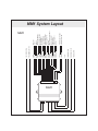
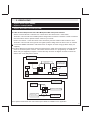
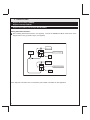
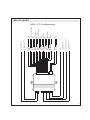
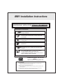
MM1 Installation Instructions
PROFESSIONAL INSTALLATION STRONGLY RECOMMENDED
Installation Precautions:
Roll down window to avoid locking keys in vehicle
during installation
Avoid mounting components or routing wires near
hot surfaces
Avoid mounting components or routing wires near
moving parts
Tape or loom wires under hood for protection and
appearance
Use grommets when routing wires through metal
surfaces
Use a Digital Multi Meter for testing and verifying
circuits. DO NOT USE A TEST LIGHT, OR
"COMPUTER SAFE PROBE" as these can set off air
bags or damage vehicle computers.
Technical Support (800) 421-3209
or go to
http://techservices.codesystems.com
FCC COMPLIANCE
This device complies with Part 15 of the FCC rules and with RSS-210 of Industry Canada.
Operation is subject to the following two conditions:
1. This device may not cause harmful interference, and
2. This device must accept any interference received, including any interference that may cause
undesired operation.
Warning! Changes or modifications not expressly approved by the party responsible for
compliance could void the user’s authority to operate the equipment.
1
2
MM1
STARTER KILL MOTOR SIDE
STARTER KILL KEY SIDE
PURPLE
PURPLE/RED
TRACKING PORT
DBI - DATABUS PORT
OVERRIDE BUTTON
L.E.D.
UNLOCK (-)
LOCK (-)
TRUNK (-)
MANUAL DISARM INPUT
GROUND WHEN ARMED
DOOR TRIGGER (+)
DOOR TRIGGER (-)
+12 VOLTS BATTERY
PARKING LIGHT OUTPUT
PARKING LIGHT INPUT
GROUND
UNLOCK SWITCH SENSE INPUT
MANUAL ARM INPUT
IGNITION INPUT
INSTANT TRIGGER (-)
HORN (-)
MM1
GREEN
BLUE
TAN
BROWN
ORANGE
PURPLE
GREEN/VIOLET
RED
WHITE
WHITE/RED
BLACK
LT. GREEN
WHITE/BLUE
PINK
BLUE/WHITE
BROWN/BLACK
PROGRAMMING BUTTON
SHOCK SENSOR DIAL
MM1 System Layout
SETUP & PROGRAMMING - CONSUMER MODE
Consumer Mode Transmitter Programming Bank 1 (3 Chirps)
1.
2.
3.
4.
5.
6.
Turn the ignition ON.
Press and hold the override button.
Within 10 seconds the system will chirp (3) three times.
Press Button 1 of each transmitter you wish to program.
The system will respond with 1 chirp for each accepted transmitter.
Pressing the override button at anytime during programming will advance to the next bank.
Note: This system has 1 button programming which programs all channels of the transmitter to the
system at once.
Consumer Mode Feature Programming Bank 2 (4 Chirps) - No Transmitters
1. Turn the ignition ON.
2. Press and hold the override button.
3. Within 10 Seconds the system will chirp (3) three times.
4. Use the override button to advance to feature programming bank 2 which is (4) four chirps.
5. Use the override button to scroll through the selections in the feature bank, the system will chirp to
match the feature number.
6. Press the programming button on the module to change the desired feature. The LED will flash
indicating the changed feature.
Consumer Mode Feature Programming Bank 2 (4 Chirps) - With Transmitters
1. Turn the ignition ON.
2. Press and hold the override button.
3. Within 10 Seconds the system will chirp (3) three times.
4. Use the override button to advance to feature programming bank 2 which is (4) four chirps.
5. Use the CAR FIND/PANIC button to scroll through the selections in the feature bank, the system will
chirp to match the feature number.
6. Press the LOCK button to change the desired feature. The LED will flash indicating the changed
feature.
Defaulting the Features in Programming Bank 2
1. Turn the ignition ON.
2. Press and hold the override button.
3. Within 10 seconds the system will chirp (3) three times.
4. Press the programming button on the module, the system will chirp (4) four times indicating the
features have been defaulted and is now in feature programming bank 2.
NOTE: The system will remain in programming mode as long as the ignition is on, there is no
time limit. To exit programming turn the IGNITION OFF.
3
MM1 - Consumer Mode Programming Guide
Feature Bank 1 - 3 Chirps
Feature Bank 2 - 4 Chirps
Transmitter Programming
1 LED Flash
2 LED Flashes
1. Security Function
ON
OFF
2. Passive Locks
Passive
Active
3. Silent Choice
ON
OFF
4. Passive/Active Arming
Passive
Active
5. Siren/Horn
Siren
Horn
6. Door Trigger Delay
Instant
30 sec.
7. Chirps
ON
OFF
8. Extended Locks
0.9 sec.
3 sec.
9. Ignition Controlled Locks
ON
OFF
10. Tan Wire Output
Trunk
2nd Unlock
11. Unlock Switch Sense
NEG
POS
12. Horn Output Timing
16mS
40mS
13. Real Panic Sound
ON
OFF
3 LED Flashes
4 LED Flashes
Dbl pulse U/L
Illum. Entry
ITS Function
72mS
Note: Default settings are in BOLD print.
Changing option #10 to ITS Function changes the functionality of the entire system, refer to the MM1 ITS
Functionality section on page 20 of this manual.
4
TRANSITIONING BETWEEN MODES
Transitioning into Lot Mode
1.
2.
3.
4.
5.
6.
Turn the ignition ON.
Press and hold the override button.
Within 10 seconds the system will chirp (3) three times.
Enter the desired VEHICLE NUMBER into the ACM keypad and then press the LOCK button.
The system will respond with 1 chirp.
Pressing the override button at anytime during programming will advance to the next bank.
Note: This system has 1 button programming which programs all channels of the transmitter to the
system at once.
Use of an ACM keypad is required.
Once an ACM keypad is programmed to the system, it is automatically transitioned into Lot Mode.
Only 1 vehicle number may be learned to the system.
When in lot mode, a consumer remote can not be programmed to the system until it is transitioned to
consumer mode.
All programming features will be defaulted to the factory default settings.
Transitioning into Consumer Mode
1. Open a vehicle door.
2. Enter the vehicle number into an ACM keypad.
3. Press the UNLOCK button.
4. Press and hold the # button until the system chirps 3 times.
5. Press and hold the # button until the system chirps 3 times again.
6. Within 5 seconds program a consumer remote. If no remotes are programmed in the 5 second
window, the system will default to a factory keyless upgrade setting which uses the factory remote
controls to arm and disarm the system.
Note: The ACM keypad must be authorized for transitioning.
Programming features 1-4 will be defaulted to the factory default settings, programming features 5-13 will
retain any changes that have been made.
ON BOARD SHOCK SENSOR
Adjusting the Shock Sensor
1. Increase sensitivity by turning the adjustment dial clockwise.
2. Decrease sensitivity by turning the adjustment dial counter clockwise.
Testing the Shock Sensor
Arm the system and wait 6 seconds for the zone to stabilize, then firmly strike the vehicles bumper.
5
SETUP & PROGRAMMING - LOT MODE
Lot Mode Transmitter Programming Bank 1 (3 Chirps)
1.
2.
3.
4.
5.
6.
Turn the ignition ON.
Press and hold the override button.
Within 10 seconds the system will chirp (3) three times.
Enter the desired VEHICLE NUMBER into the ACM keypad and then press the LOCK button.
The system will respond with 1 chirp.
Pressing the override button at anytime during programming will advance to the next bank.
Note: This system has 1 button programming which programs all channels of the transmitter to the
system at once.
When an ACM keypad is programmed to the system, it is automatically transitioned into Lot Mode.
Only 1 vehicle number may be learned to the system.
Lot Mode Feature Programming Bank 2 (4 Chirps) - No ACM Transmitter
1. Turn the ignition ON.
2. Press and hold the override button.
3. Within 10 Seconds the system will chirp (3) three times.
4. Use the override button to advance to feature programming bank 2 which is (4) four chirps.
5. Use the override button to scroll through the selections in the feature bank, the system will chirp to
match the feature number.
6. Press the programming button on the module to change the desired feature. The LED will flash
indicating the changed feature.
Consumer Mode Feature Programming Bank 2 (4 Chirps) - With ACM Transmitter
1. Turn the ignition ON.
2. Press and hold the override button.
3. Within 10 Seconds the system will chirp (3) three times.
4. Use the override button to advance to feature programming bank 2 which is (4) four chirps.
5. Use the CAR FIND/PANIC button to scroll through the selections in the feature bank, the system will
chirp to match the feature number.
6. Press the LOCK button to change the desired feature. The LED will flash indicating the changed
feature.
Defaulting the Features in Programming Bank 2
1. Turn the ignition ON.
2. Press and hold the override button.
3. Within 10 seconds the system will chirp (3) three times.
4. Press the programming button on the module, the system will chirp (4) four times indicating the
features have been defaulted and is now in feature programming bank 2.
NOTE: The system will remain in programming mode as long as the ignition is on, there is no
time limit. To exit programming turn the IGNITION OFF.
6
MM1 - Lot Mode Programming Guide
Feature Bank 1 - 3 Chirps
Feature Bank 2 - 4 Chirps
Transmitter Programming
1 LED Flash
2 LED Flashes
ON
OFF
2. Passive Locks
Passive
Active
3. Silent Choice
ON
OFF
4. Passive/Active Arming
Passive
Active
5. Siren/Horn
Siren
Horn
6. Door Trigger Delay
Instant
30 sec.
7. Chirps
ON
OFF
8. Extended Locks
0.9 sec.
3 sec.
9. Ignition Controlled Locks
ON
OFF
10. Tan Wire Output
Trunk
2nd Unlock
11. Unlock Switch Sense
NEG
POS
12. Horn Output Timing
16mS
40mS
13. Real Panic Sound
ON
OFF
14. Lot Alert
OFF
ON
1. Security Function
3 LED Flashes
4 LED Flashes
Dbl pulse U/L
Illum. Entry
ITS Function
72mS
Note: Default settings are in BOLD print.
Changing feature #10 to ITS Function changes the functionality of the entire system, refer to the MM1 ITS
Functionality section of this manual.
7
1. 2 PIN STARTER KILL HARNESS
Starter Input (Key Side) (PURPLE/RED) / Starter Output (Motor Side) (PURPLE)
Locate the vehicle starter wire.
Verification: This wire registers voltage only when the key is turned to the START position. Cut the vehicle's
starter wire in half.
Verification after starter wire is cut:
• KEY SIDE of starter wire registers voltage when the key is turned to the START position.
• MOTOR SIDE of starter wire registers no voltage.
Connect the PURPLE/RED wire to the KEY SIDE of the vehicle starter wire at the ignition switch harness.
Connect the PURPLE wire to the MOTOR SIDE of the vehicle starter wire.
2. BASIC INSTALLATION - 16 PIN MAIN HARNESS
Negative Unlock Output (GREEN)
Negative Lock Output (BLUE)
Refer to the door lock section of this manual.
Trunk Release Output (-) (TAN)
This wire provides a 500mA negative output capable of driving relays. For Control of optional accessories
such as trunk release.
To Activate press and hold UNLOCK for 2 seconds.
Locate the vehicle’s trunk release wire at the trunk release switch.
Verification: This wire will register either positive voltage or ground when the trunk release is activated.
Optional Programmable Settings: This output can also be used for 2nd step unlock, Illuminated Entry, or ITS
Function.
Note: Changing this to ITS Function changes the functionality of the entire system, refer to the MM1 ITS
Functionality section of this manual.
8
2. 16 PIN MAIN HARNESS CONTINUED
Manual DISARM Input (BROWN)
This wire will DISARM the security system when a POS or NEG pulse is applied to it from an external device
such as the vehicle's factory unlock motor wire.
Ground When Armed Output (-) 500mA (ORANGE)
This wire will show Ground when the system is Armed. This wire is used for controlling window modules or
additional sensors.
Positive Door Input (+) (PURPLE)
Locate the vehicle’s dome light or door pin switch wire.
Verification: This wire will register positive voltage (POS) when the door is opened and the interior light is
on. This wire will register ground or "0" Volts when the door is closed and the interior light is off.
Connect the PURPLE wire to the vehicle’s positive door input wire(s).
NOTE: Certain vehicles may require multiple connections. Refer to vehicle application guide
Negative Door Input (-) (GREEN/VIOLET)
Locate the vehicle’s dome light or door pin switch wire.
Verification: This wire will register ground (NEG) when the door is opened and the interior light is on. This
wire will register positive voltage when the door is closed and the interior light is off.
Connect the GREEN/VIOLET wire to the vehicle’s negative door input wire(s).
NOTE: Certain vehicles may require multiple connections. Refer to vehicle application guide
Battery Power (RED)
Locate 1 of the vehicle’s constant 12 Volt battery wires at the ignition switch.
Verification: This wire will register voltage in all positions of the ignition switch.
Connect the RED wire to the constant 12 Volt battery wire.
Note: Remove the 3 Amp fuse until all connections are made.
Parking Light Output (+/-) (WHITE) Parking Light Polarity (WHITE/RED)
Locate the vehicle’s parking light wire at the vehicle light switch.
Verification: This wire will register positive voltage or ground when the vehicle parking light switch is turned
to the ON position.
These wires are the COMMON and NORMALLY OPEN contacts of the on-board parking light relay. If the
vehicle's parking lights are a +12 volt switched system, connect the RED/WHITE wire to a fused +12 volt
battery source, and connect the WHITE wire to the vehicle's parking light wire. If the vehicle's parking lights
are a chassis ground switched system, connect the RED/WHITE wire to a chassis ground source, and
connect the WHITE wire to the vehicle's parking light wire.
9
2. 16 PIN MAIN HARNESS CONTINUED
Chassis Ground Source (-) (BLACK)
Connect the BLACK wire to a solid chassis ground point using a ring terminal and self tapping screw
(not supplied). Scrape away paint from the grounding point to ensure a good connection. The
recommended grounding point is a metal surface in the driver’s side kick panel area.
Note: Do not ground the BLACK wire with any other vehicle components.
Unlock Switch Sense (LT. GREEN)
This wire will prevent the system from disarming the security system when a POS or NEG pulse is applied to
it from an external device. This will prevent the system from disarming if it is pulsed at the same time as the
BROWN (Manual Disarm Input) wire.
For example: To prevent the system from disarming from the switch on the door. Connect this wire to the unlock
switch or passenger unlock motor wire
NOTE: Only required if using the factory keyless entry transmitter to ARM/DISARM this system.
Manual ARM input (WHITE/BLUE)
This wire will ARM the security system when a POS or NEG pulse is applied to it from an external device such
as the vehicle's factory lock motor wire.
12 volts Ignition Input (PINK)
Locate the vehicle’s ignition wire at the ignition switch.
Verification: This wire registers voltage when the key is turned to the ON (or RUN) position. The voltage
does not drop out when the key is turned to the START (or CRANK) position.
Connect the PINK wire to the vehicle’s Ignition wire.
Instant Trigger Input (-) (BLUE/WHITE)
This wire is a GROUND input for an external sensor or secondary pin switch.
Verification: This wire when connected will trigger the security system
Horn Output (-) 1Amp (BROWN/BLACK)
Locate the vehicle’s horn wire at the steering column.
Verification: This wire will register at positive voltage and register ground when the horn switch is
pressed.
Connect the BROWN/BLACK wire to the vehicle’s horn wire.
3. DOOR LOCKS
Negative Unlock Output (GREEN)
Negative Lock Output (BLUE)
Negative Second Door Unlock Output (TAN)
The door lock / unlock outputs are designed to control several different types of systems which may
require additional parts. Please review the wire and location chart to see which type of door lock system
is in your vehicle. The most common types are shown in the diagrams below.
Negative Switching and Negative Switching with 2-step unlock feature:
All Door Lock and Unlock: Locate the lock / unlock wire at the vehicle’s lock / unlock switch.
Verification: These wires will register ground when the Lock and Unlock switches are activated.
Driver’s Door Unlock: Locate the unlock motor wire directly from the actuator inside the driver’s door.
Verification: This wire will rest at ground and register positive voltage when the driver’s door is unlocked.
Connect the GREEN and BLUE or TAN wires shown in diagram 6 below.
Note: When adding the 2 step unlock feature the TAN 2nd door unlock wire will be used to unlock all
vehicle doors on the second press of unlock. This feature must be turned on in programming. An
additional SPDT relay (not supplied) is required. Connect the relay as shown in diagram 7 below to
unlock the driver’s door on the first press of unlock.
Diagram 6
Door Lock S witch
B LUE (-) Lock Output
Lock
Vehicle Door Lock
C ontrol R elays
Unlock
G R E E N (-) Unlock Output Or T AN (-) 2nd Door
Unlock Output when Installing T he 2-S tep Unlock
Diagram 7
F us ed +12 Volt
B attery S ource
87
87a
G R E E N (-) Unlock Output
85
86
30
From Keyles s E ntry
Module Or Door
Lock/Unlock R elays
X
To Unlock S ide Of
Driver's Door Actuator
C UT
11
3. DOOR LOCKS
Negative Unlock Output (GREEN)
Negative Lock Output (BLUE)
Negative Second Door Unlock Output (TAN)
Positive Switching and Positive Switching with 2-step unlock feature:
All Door Lock and Unlock: Locate the lock / unlock wire at the vehicle’s lock / unlock switch.
Verification: These wires will register positive voltage when the Lock and Unlock switches are activated.
Driver’s Door Unlock: Locate the unlock motor wire directly from the actuator inside the driver’s door.
Verification: This wire will rest at ground and register positive voltage when the driver’s door is unlocked.
Connect the GREEN and BLUE or TAN wires shown in diagram 8 below.
Note: When adding the 2 step unlock feature the TAN 2nd door unlock wire will be used to unlock all vehicle
doors on the second press of unlock. This feature must be turned on in programming. Three additional
SPDT relays (not supplied) are required. Connect the relays as shown in diagram 9 below to unlock the
driver’s door on the first press of unlock.
Diagram 8
F us ed +12 V olt
B attery S ource
87
87a
85
86
Door Lock S witch
B LUE (-) Door
lock Output
30
Lock
F us ed +12 V olt
B attery S ource
Vehicle Door Lock
C ontrol R elays
87
Unlock
87a
85
86
G R E E N (-) or T AN (-)
2nd Door Unlock Output
30
Diagram 9
F us ed +12 Volt
B attery S ource
87
G R E E N (-) Unlock Output
87a
85
86
30
From Keyles s E ntry
Module Or Door
Lock/Unlock R elays
12
X
C UT
To Unlock S ide Of
Driver's Door Actuator
3. DOOR LOCKS
Negative Unlock Output (GREEN)
Negative Lock Output (BLUE)
Negative Second Door Unlock Output (TAN)
Reverse Polarity (5-Wire Doorlocks) and Reverse Polarity with 2-step Unlock
All Door Lock and Unlock: Locate the lock / unlock wire at the vehicle’s lock / unlock switch.
Verification: These wires will rest at ground and register positive voltage when the Lock and Unlock
switches are activated.
Driver’s Door Unlock: Locate the unlock motor wire directly from the actuator inside the driver’s door.
Verification: This wire will rest at ground and register positive voltage when the driver’s door is unlocked.
Connect the GREEN and BLUE or TAN wires shown in diagram 10 below using (2) SPDT relays (not
supplied).
Note: When adding the 2 step unlock feature the TAN 2nd door unlock wire will be used to unlock all vehicle
doors on the second press of unlock. This feature must be turned on in programming. An additional
SPDT relay (not supplied) is required. Connect the relays as shown in diagram 11 below to unlock the
driver’s door on the first press of unlock
Diagram 10
F us ed +12 Volt
B attery S ource
87
Mas ter Door
L ock S witch
87a
B L UE (-) L ock O utput
85
86
30
L ock
To Door L ock
Actuators
X
C ut
Unlock
F us ed +12 Volt
B attery S ource
87
G R E E N (-) Unlock O utput
O r T AN (-) 2nd Door
Unlock O utput
87a
85
86
30
To Door L ock
Actuators
X
C ut
Diagram 11
F us ed +12 V olt
B attery S ource
87
87a
G R E E N (-) Unlock Output
85
86
30
F rom K eyles s E ntry
Module Or Door
Lock/Unlock R elays
X
T o Unlock S ide Of
Driver's Door Actuator
C UT
Note. Optional Code Alarm door lock interface part # DLRK is available for this application.
13
3. DOOR LOCKS
Negative Unlock Output (GREEN)
Negative Lock Output (BLUE)
Negative Second Door Unlock Output (TAN)
One Wire Negative Multiplexed and One Wire Negative Multiplexed with 2-step Unlock Feature
All Door Lock and Unlock: Locate the lock / unlock wire at the vehicle’s lock / unlock switch.
Verification: This wire will show variable ground when the switch is activated. Please consult the wire and
location chart for specific resistor values for your vehicle.
Driver’s Door Unlock: Locate the unlock motor wire directly from the actuator inside the driver’s door.
Verification: This wire will rest at ground and register positive voltage when the driver’s door is unlocked.
Connect the GREEN and BLUE or TAN wires shown in diagram 12 below using (2) SPDT relays (not
supplied).
Note: When adding the 2 step unlock feature the TAN 2nd door unlock wire will be used to unlock all vehicle
doors on the second press of unlock. This feature must be turned on in programming. An additional
SPDT relay (not supplied) is required. Connect the relay as shown in diagram 13 below to unlock the
driver’s door on the first press of unlock
Diagram 12
B LUE (-) Lock Output
Door Lock S witch
R es is tor
Lock
Vehicle Door Lock
C ontrol R elays
Unlock
R es is tor
G R E E N (-) Unlock Output Or T AN(-) 2nd Door
Unlock Output when Ins talling T he 2-S tep Unlock
Diagram 13
F us ed +12 V olt
B attery S ource
87
87a
85
86
F rom K eyles s E ntry
Module O r Door
Lock/Unlock R elays
G R E E N (-) Unlock O utput
30
T o Unlock S ide O f
Drivers Door Actuator
Note. Optional Code Alarm door lock interface part # DLRK is available for this application.
14
3. DOOR LOCKS
Negative Unlock Output (GREEN)
Negative Lock Output (BLUE)
Negative Second Door Unlock Output (TAN)
One Wire Positive Multiplexed and One Wire Multiplexed With 2-step Unlock Feature
All Door Lock and Unlock: Locate the lock / unlock wire at the vehicle’s lock / unlock switch.
Verification: This wire will show variable positive voltage when the switch is activated. Please consult the
wire and location chart for specific resistor values for your vehicle.
Driver’s Door Unlock: Locate the unlock motor wire directly from the actuator inside the driver’s door.
Verification: This wire will rest at ground and register positive voltage when the driver’s door is unlocked.
Connect the GREEN and BLUE or TAN wires shown in diagram 14 below using (2) SPDT relays (not
supplied).
Note: When adding the 2 step unlock feature the TAN 2nd door unlock wire will be used to unlock all vehicle
doors on the second press of unlock. This feature must be turned on in programming. An additional
SPDT relay (not supplied) is required. Connect the relay as shown in diagram 15 below to unlock the
driver’s door on the first press of unlock.
Diagram 14
G R E E N (-) Unlock Output
Or T AN 2nd Door Unlock
Output When Ins talling
T he 2-S tep Unlock F eature
F us ed +12 Volt
B attery S ource
B LUE (-) Lock Output
87
87
Door
Lock S witch
87a
87a
85
86
30
30
Lock
85
86
R es is tor
R es is tor
Vehicle Door Lock
C ontrol R elays
Unlock
Diagram 15
F us ed +12 Volt
B attery S ource
87
87a
G R E E N (-) Unlock Output
85
86
30
From Keyles s E ntry
Module Or Door
Lock/Unlock R elays
X
To Unlock S ide Of
Driver's Door Actuator
C UT
Note. Optional Code Alarm door lock interface part # DLRK is available for this application.
15
3. DOOR LOCKS
Negative Unlock Output (GREEN)
Negative Lock Output (BLUE)
Negative Second Door Unlock Output (BLUE/GREEN)
Adding Aftermarket Actuators
After installing aftermarket actuators, (not supplied). Connect the GREEN and BLUE wires shown in the
diagram below using (2) SPDT relays (not supplied).
F used +12 Volt
B attery S ource
87
Door Lock
Actuator
87a
B LUE (-) Lock Output
85
86
30
C hassis
G round
M
F used +12 Volt
B attery S ource
87
87a
G R E E N (-) Unlock Output
85
86
30
C hassis
G round
Note. Optional Code Alarm door lock interface part # DLRK is available for this application.
16
4. ACCESSORY CONNECTORS
2 Pin Override Push-Button Switch: (Blue Connector)
The BLACK and GRAY twin lead wires loaded in the two pin blue connector are the ground supply and
override input of the Remote Start unit. Drill a 1/4" hole and mount this switch in an easily accessible
location under the driver's dashboard.
2 Pin LED Harness: (White Connector)
The RED & BLUE wires loaded into the two pin mini white connector control the anode and cathode of the
dash mounted LED. Drill a 1/4" hole and mount the LED in an easy to see location on the dashboard. Be
careful to check to make sure that there is enough clearance behind the panel you are drilling into.
4 Pin Tracking Port: (Off White Connector)
This 4 pin port is used for connecting the PROPT20 Pursuitrak GPS system.
4 Pin Data Bus Interface Port: (Brown Connector)
This 4 pin port is used for Code Alarm Door Lock and Transponder Databus Interfaces to communicate
with the vehicle's Databus. When using the DBI port to control the Code Alarm Door Lock and Transponder
Interface modules the following options may be available. Please refer to the D2D (Data to Data) function
list available per vehicle on the tech service web site.
Door Trigger
Trunk/Hatch Open
Keyless Entry Control
Dome Light Supervision
Factory Alarm Arm / Disarm
Manual Arm / Disarm Inputs (factory keyless controls system)
17
5. SYSTEM POWER-UP PROCEDURE
1. After all connections are complete, turn the vehicle's ignition key to the ON position.
2. Insert the 3 Amp fuse into the respective fuseholder.
3. Turn the ignition key to the OFF position.
6. System Testing
1. Follow each instruction below.
2. Verify that the system operates as indicated under each instruction. Refer to the system owners manual.
3. Check the appropriate wire connections and/or fuses if the unit fails to perform a specific function. Also
check that any options pertaining to the function are programmed properly.
Security Operation
Press LOCK once:
1. Doors lock.
2. Courtesy lights (if on) shut off.
3. Unit checks to see if doors, hood or trunk are open. If open, siren (or horn) sounds once, parking lights
flash once, and system enters pre-arm mode.
Pre-arm mode:
1. The unit will wait for the open door, hood or trunk to be closed. The LED is solid during pre-arm.
2. If the entrance is secured, the siren/horn will sound again, parking lights will flash once, and the system
will arm.
3. If the entrance is not secured after 4 minutes, the siren/horn will sound again, parking lights will flash
once, the system will arm, and the defective trigger or entrance will be ignored.
Note: If entrance is secured after 4 minutes, the system will immediately begin to monitor the entrance for
intrusion.
If the above conditions are not present:
1. Vehicle starter is disabled.
2. Siren (or horn) sounds twice / parking lights flash twice.
3. LED (Red light) flashes slowly for duration of arm cycle.
4. After 5 seconds, unit monitors all entrances and sensors.
If door, sensor, hood/trunk or ignition input is triggered:
1. Siren/horn sounds for 30 seconds or until UNLOCK is pressed.
2. Parking lights flash.
3. If the alarm system is triggered, pressing UNLOCK (once) will end the 30-second cycle.
Pressing UNLOCK after a full 30 second trigger cycle has completed, the horn will honk 4 times and the
LED will flash a number of times to indicate which input triggered the alarm. Turning on the ignition or
pressing the valet/override button will reset the LED flashes, pressing the valet/override button will also
honk the horn to match the LED flashes before it resets.
Number of flashes:
1 - Interior Theft Sensor (Shock Sensor)
2 - Door Input
4 - Trunk input
5 - Ignition
18
6. System Testing Cont.
Press DISARM:
1. Doors unlock.
2. Factory alarm (if equipped) is turned off.
3. Siren/horn sounds once/ parking lights flash once.
4. Courtesy lights turn on for 30 seconds, or until ARM is pressed or ignition is turned on.
5. Vehicle starter is enabled.
Press DISARM twice:
Passenger doors unlock if using 2-stage unlock.
Press CAR FIND/PANIC:
Siren/horn sounds 5 times.
Press and hold CAR FIND/PANIC for 2 seconds:
Siren/horn sounds and lights flash for 30 seconds or until any remote control button is pressed.
Press and hold UNLOCK:
Trunk or hatch opens, or other device activates.
If the Ignition Controlled Locks option is set to On:
Doors lock when all doors are closed and the ignition is turned ON.
Doors unlock when ignition is turned OFF.
7. Mounting the Module / Finishing the Installation
1. Attach the module to the module mounting clip.
2. Mount the module to a brace or wire harness under the dash. The module and harnesses must be clear of
moving parts.
Installation Complete.
19
MM1 ITS Functionality
MM1 ITS Introduction
The MM1 may be used as a MM1 ITS (Interior Theft Sensor) and when doing so it is designed to honk the horn if
a light impact is detected or trigger the vehicle's factory alarm if a harder impact is detected.
Note: The vehicle MUST have a factory alarm that is triggered by opening the vehicle's door.
Option #10 must be changed in the MM1 programming bank for this to function as the MM1 ITS.
MM1 ITS ACTIVATION
Optional Warn Away
The optional Warn-Away Trigger is active after the ignition key is turned off and the dome light shuts off after exiting
the vehicle. When a light impact is detected the system will briefly honk the vehicles horn. If at any time a door is
opened (dome light "on"), the Warn-Away Trigger will be bypassed until the ignition key is cycled "ON" and "OFF".
This feature prevents the Warn-Away chirps of the vehicle's horn when the customer/user enters the vehicle. The
Warn-Away Trigger will reactivate when the ignition key is cycled "ON" and "OFF" again.
Factory Alarm Trigger
The MM1 ITS Factory Alarm Trigger is active 5 minutes after the ignition is turned off and the factory alarm has been
set. When a heavy impact is detected the MM1 ITS will pulse the vehicle's door trigger wire to active the factory
alarm.
Valet Mode
Valet Mode deactivates both the optional Warn-Away and Factory Alarm Trigger. To turn Valet Mode ON, turn the
ignition key ON/OFF three times. To turn Valet Mode "OFF", turn the ignition key ON/OFF three times.
16 Pin Harness Connections
TAN - Factory Alarm Trigger: Connect this to a wire which triggers the vehicle's factory alarm system such as the
door ajar, hood or trunk wire.
PURPLE and GREEN/VIOLET - Door Inputs (+/-): Connect one of these wires to the vehicle's dome light wire.
RED - +12 Volt Input: Connect this wire to constant +12 volt source.
BLACK - Ground Input: Connect this wire to chassis ground.
PINK - Ignition Input: Connect this wire to +12 volt ignition source.
BROWN/BLACK - Warn Away Horn Output: Connect this wire to the vehicle's horn wire.
NOTES:
The MM1 ITS uses the PURPLE or GREEN/VIOLET (Door Input) to DISARM the optional Warn-Away feature. The
PURPLE or GREEN/VIOLET must sense all of the doors for the MM1 ITS to DISARM properly. It is recommended
to only use the Warn-Away feature with vehicle's that have an "ALL" door trigger output in the vehicle.
20
N/A
N/A
PURPLE
PURPLE/RED
TRACKING PORT - N/A
DBI - DATABUS PORT - N/A
OVERRIDE BUTTON
L.E.D.
N/A
N/A
FACTORY ALARM TRIGGER
N/A
N/A
DOOR INPUT (+)
DOOR INPUT (-)
+12 VOLTS BATTERY
N/A
N/A
GROUND
N/A
N/A
IGNITION INPUT
N/A
HORN (-)
GREEN
BLUE
TAN
BROWN
ORANGE
PURPLE
GREEN/VIOLET
RED
WHITE
RED/WHITE
BLACK
LT. GREEN
WHITE/BLUE
PINK
BLUE/WHITE
BROWN/BLACK
PROGRAMMING BUTTON
SHOCK SENSOR DIAL
MM1 ITS LAYOUT
MM1 / ITS Configuration
21
22