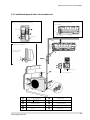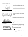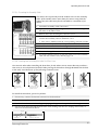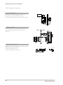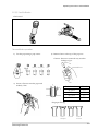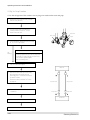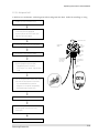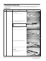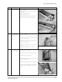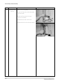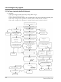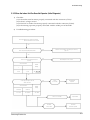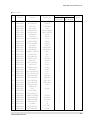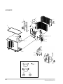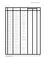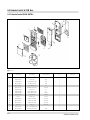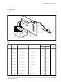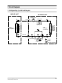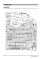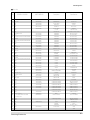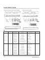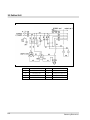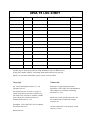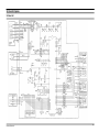
1
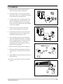
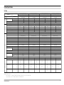
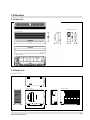
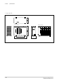
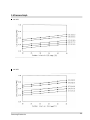
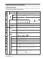
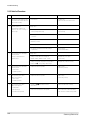
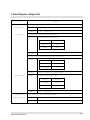
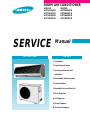
ROOM AIR CONDITIONER
INDOOR
AQT24A1QE/B
AQT24B1QE/B
AQT18A1QE/B
AQT18B1QE/B
SERVICE
INDOOR
AQT24A2QE/B
AQT24B2QE/B
AQT18A2QE/B
AQT18B2QE/B
Manual
AIR CONDITIONER
CONTENTS
1. Precautions
2. Product Specifications
3. Operating Instructions and
Installation
4. Disassembly and Reassembly
5. Troubleshooting
6. Exploded Views and Parts List
7. Block Diagrams
8. PCB Diagrams
9. Wiring Diagrams
10. Schematic Diagrams
© Samsung Electronics Co., Ltd. DEC. 1998.
Printed in Korea.
Code No. DB81-00029A(1)
1. Precautions
1. Warning: Prior to repair, disconnect the
power cord from the circuit breaker.
2. Use proper parts: Use only exact replacement parts. (Also, we recommend replacing
parts rather than repairing them.)
3. Use the proper tools: Use the proper tools
and test equipment, and know how to use
them. Using defective tools or test equipment may cause problems later-intermittent
contact, for example.
Fig. 1-1 Avoid Dangerous Contact
4. Power Cord: Prior to repair, check the
power cord and replace it if necessary.
5. Avoid using an extension cord, and avoid
tapping into a power cord. This practice
may result in malfunction or fire.
6. After completing repairs and reassembly,
check the insulation resistance. Procedure:
Prior to applying power, measure the resistance between the power cord and the
ground terminal. The resistance must be
greater than 30 megohms.
Fig. 1-2 No Tapping and No Extension Cords
7. Make sure that the grounds are adequate.
8. Make sure that the installation conditions
are satisfactory. Relocate the unit if necessary.
9. Keep children away from the unit while it is
being repaired.
10. Be sure to clean the unit and its surrounding area.
Fig. 1-3 No Kids Nearby!
Fig. 1-4 Clean the Unit
Samsung Electronics
1-1
MEMO
1-2
Samsung Electronics
2. Product Specifications
2-1 Table
Model
Item
Power Sourse
Capacity (ISO/SASO)
Performance Air circulation (High)
Moisture removal (High)
Available voltage range
Running amperes (ISO/SASO)
Electrical Power input (ISO/SASO)
Rating Power factor (ISO/SASO)
Energy efficiency ratio (ISO/SASO)
Compressor locked rotor amperes
Controls/Temperature control
Control unit
Timer
Fan speed
Airflow direction (indoor)
kcal/h
BTU/h
m2/min
Liters/h
V
A
kw
%
BTU/wh
A
Indoor/Outdoor
Horizontal
Vertical
Comperssor
Refrigerant/Amount charged at rating
Features
Refrigerant control
Operation sound
Indoor Hi/Me/Lc
Outdoor-Hi
Refrigerant tubing connections
Max. allowable tubing length at shippint
Refrigerant tube diameter Narrow tube
Wide tube
Refrigerant tube kit/Accessories
Unit dimensions
Dimensions
Package dimensions
&
Weight
Weight
Remarks : Rating Conditions are :
Indoor air temperature
Outdoor air temperature
Samsung Electronics
Height
Width
Depth
Height
Width
Depth
Net
Shipping
g
dB-A
dB-A
m
(in.)
(in.)
mm
mm
mm
mm
mm
mm
kg
kg
AQT24A1(B1)QE/AQT24A2(B2)QE
Heat Pump
220-240V~, 50Hz
6,048
6,048
24,000
24,000
14.0
14.5
3.0
198 ~ 264
12.5
13.0
2.6
2.7
86.7
86.5
9.2
8.9
82
Microprocessor / I.C Thermostat
Wireless remote control
Q-Timer / 24-Hour ON or OFF
3 Steps and Turbo / 1 Step
Manual
Auto
Reciprocating(Tecumseh)
R22 / 1600g
Capillary tube
45 / 43 / 41
58
Flare type
10
6.35(1/4”)
15.88(5/8”)
Optional / Hanger-plate
Indoor unit
Outdoor
275
638
1080
880
204
310
372
851
1153
1023
272
413
13
63.0
16
67.0
AQT24A1(B1)QB/AQT24A2(B2)QB
Heat Pump
220V~, 60Hz
5,040
6,048
20,000
24,000
14.0
14.5
3.0
187 ~ 253
13.8
13.5
2.95
2.7
97.7
90.9
6.8
8.9
73
Microprocessor / I.C Thermostat
Wireless remote control
Q-Timer / 24-Hour ON or OFF
3 Steps and Turbo / 1 Step
Manual
Auto
Reciprocating(Tecumseh)
R22 / 1600g
Capillary tube
45 / 43 / 41
58
Flare type
10
6.35(1/4”)
15.88(5/8”)
Optional / Hanger-plate
Indoor unit
Outdoor
275
638
1080
880
204
310
372
851
1153
1023
272
413
13
63.0
16
67.0
AQT18A1(B1)QE/AQT18A2(B2)QE
Heat Pump
220-240V~, 50Hz
4,536
5,040
18,000
20,000
13.5
14.0
2.5
198 ~ 264
9.5
10.0
2.0
2.1
87.7
87.5
9.0
9.5
54
Microprocessor / I.C Thermostat
Wireless remote control
Q-Timer / 24-Hour ON or OFF
3 Steps and Turbo / 1 Step
Manual
Auto
Reciprocating(Tecumseh)
R22 / 1500g
Capillary tube
45 / 42 / 39
57
Flare type
10
6.35(1/4”)
12.70(1/2”)
Optional / Hanger-plate
Indoor unit
Outdoor
275
620
1080
787
204
320
372
680
1153
926
272
451
13
58.0
16
62.0
AQT18A1(B1)QB/AQT18A2(B2)QB
Heat Pump
220V~, 60Hz
4,000
5,040
16,000
20,000
13.5
14.0
2.5
187 ~ 253
10.5
10.5
2.25
2.1
97.4
90.9
7.1
9.5
52
Microprocessor / I.C Thermostat
Wireless remote control
Q-Timer / 24-Hour ON or OFF
3 Steps and Turbo / 1 Step
Manual
Auto
Reciprocating(Tecumseh)
R22 / 1500g
Capillary tube
45 / 42 / 39
57
Flare type
10
6.35(1/4”)
12.70(1/2”)
Optional / Hanger-plate
Indoor unit
Outdoor
275
620
1080
787
204
320
372
680
1153
926
272
451
13
58.0
16
62.0
ISO(50Hz) : 27˚C DB/19.0˚C WB, ISO(60Hz) : 27.0˚C DB/19.5˚C WB, SASO : 29.0˚C DB/19.0˚C WB
ISO : 35.0˚C DB/24.0˚C WB, SASO : 46.0˚C DB/24.0˚C WB
2-1
2-2 Major Component specifications
■
Indoor unit
Model
Part No.
PCB
Controls
Control circuit fuse
Type
Dia. and length
Fan motor model
Pols,rpm(at 240V)
Fan & Fan Normal out
Motor Coil resistance(Ambient temp.20˚C)
Safety devices
S-Motor
Heat
Exch.
■
Type
Operating temp.
Run capacitor
Type
Model
Rating
Coil resistance (Ambient temp. 25˚C)
Coil
Rows x Steps
Fin pitch
Face area
mm
W
Ω
Open
˚C
µF x VAC
Ω
mm
m2
AQT24A1(B1)QE/AQT24A2(B2)QE
PD-Q24B1Q-03
Microprocessor
250V, 3.15A
Cross-Flow
ø95/L = 842
IC-9430SKJ5A
4P, 1350 RPM
40W
MAIN : 160Ω
SUB : 227Ω
17AM034A5
135 ± 5°C
1.2µF X 450VAC
AQT24A1(B1)QB/AQT24A2(B2)QB
PD-Q24B1Q-03
Microprocessor
250V, 3.15A
Cross-Flow
ø95/L = 842
IC-9430SKF6A
4P, 1350 RPM
40W
MAIN : 140Ω
SUB : 280Ω
17AM034A5
135 ± 5°C
1.2µF X 450VAC
AQT18A1(B1)QE/AQT18A2(B2)QE
PD-Q24B1Q-04
Microprocessor
250V, 3.15A
Cross-Flow
ø95/L = 842
IC-9430SKJ5A
4P, 1350 RPM
40W
MAIN : 160Ω
SUB : 227Ω
17AM034A5
135 ± 5°C
1.2µF X 450VAC
AQT18A1(B1)QB/AQT18A2(B2)QB
PD-Q24B1Q-04
Microprocessor
250V, 3.15A
Cross-Flow
ø95/L = 842
IC-9430SKF6A
4P, 1350 RPM
40W
MAIN : 140Ω
SUB : 280Ω
17AM034A5
135 ± 5°C
1.2µF X 450VAC
MSFCC20A03
DC 12V
530Ω
AL-FIN/Copper tube
2 x 15
1.2
0.315
MSFCC20A03
DC 12V
530Ω
AL-FIN/Copper tube
2 x 15
1.2
0.315
MSFCC20A03
DC 12V
530Ω
AL-FIN/Copper tube
2 x 15
1.5
0.315
MSFCC20A03
DC 12V
530Ω
AL-FIN/Copper tube
2 x 15
1.5
0.315
UQT24A1(B1)QE/UQT24A2(B2)QE
Reciprocating
AWG5532EXC
2660
WITCO LP200 OR EQUIVALENT
INITIAL : 1125 REFILL : 1066
0.92
Start winding : 2.49
Run winding : 0.81
15HM2415-148
Internal Line Break
120
69
73.0 AT 2-10 SECOND
45MF X 370VAC
Propeller
ø460
OSME-716SRC
6P, 850 RPM
70W
MAIN : 58Ω - 88Ω
SUB : 85Ω - 150Ω
17AM034A5
135±5°C
UQT24A1(B1)QB/UQT24A2(B2)QB
Reciprocating
AWG5528EXN
2830
WITCO LP200 OR EQUIVALENT
INITIAL : 1125 REFILL : 1066
0.92
Start winding : 1.94
Run winding : 0.88
15HM2415-148
Internal Line Break
120
69
73.0 AT 2-10 SECOND
35MF X 370VAC
Propeller
ø460
OSME-716SRC
6P, 850 RPM
70W
MAIN : 58Ω - 88Ω
SUB : 85Ω - 150Ω
17AM034A5
135±5°C
UQT18A1(B1)QE/UQT18A2(B2)QE
Reciprocating
AWG5524EXC
2030
WITCO LP200 OR EQUIVALENT
INITIAL : 1125 REFILL : 1066
0.92
Common to main : 2.98
Common to sub: 1.42
15HM2416-148
Internal Line Break
130
69
73.0 AT 2-10 SECOND
35MF X 370VAC
Propeller
ø405
AMASS-035AVEB
4P, 1050 RPM
35W
MAIN : 186Ω
SUB : 210Ω
17AM037A5
150±5°C
UQT18A1(B1)QB/UQT18A2(B2)QB
Reciprocating
AWG5520EXN
2070
WITCO LP200 OR EQUIVALENT
INITIAL : 1125 REFILL : 1066
0.92
Common to main : 2.72
Common to sub : 1.32
15HM2311-148
Internal Line Break
120
69
73.0 AT 2-10 SECOND
25MF X 370VAC
Propeller
ø405
AMASS-035ZTEA
4P, 1050 RPM
35W
MAIN : 127Ω
SUB : 165Ω
17AM037A5
150±5°C
3µF x 450VAC
AL-FIN / Copper tube
2 x 24
1.7
0.5376
3µF x 450VAC
AL-FIN / Copper tube
2 x 24
1.7
0.5376
2.5µF x 450VAC
AL-FIN / Copper tube
2 x 24
1.7
0.504
2.5µF x 450VAC
AL-FIN / Copper tube
2 x 24
1.7
0.504
Outdoor unit
Model
Type
Compressor model
Normal output
Comperssor oil kind
Comperssor oil
Oil Specific gravity
Compressor Coil resistance(Ambient temp.25˚C)
Safety devices
W
cc
Ω
Type
Overloal relay
Operating temp.
Open
˚C
Close
˚C
Operating amp(Ambient temp.)
µF x VAC
Run capacitor
Type
Dia. and length
Fan motor model
Pols, rpm(at240V)
Normal output
Fan & Fan Coil resistance(Ambient temp.20˚C)
Safety devices
Heat
Exch.
2-2
Run capacitor
Coil
Rows x Steps
Fin pitch
Face area
Type
Operating temp.
mm
W
Ω
Open
˚C
Close
˚C
µF x VAC
mm
m2
Samsung Electronics
2-3 Dimensions
2-3-1 Indoor Unit
(Remote control)
(Front view)
1080
58
204
22
(Rear view)
2-3-2 Outdoor Unit
2-3-2(a) 24K BTU
(Front view)
(Rear view)
660
878
Samsung Electronics
2-3
Product
Specifications
2-3-3(b) 18K BTU
(Front view)
(Rear view)
582
340
787
2-4
Samsung Electronics
2-4 Pressure Graph
24K BTU
18K BTU
Samsung Electronics
2-5
MEMO
2-6
Samsung Electronics
3. Operating Instructions and Installation
3-1 Operating Instructions
3-1-1 Name & Function of Key in remote controller
NO
FUNCTION OF KEY
NAMED OF KEY
On/Off Button. Use this button to start and stop air conditioner.
1
2
(UP)
Temp. up button. If the button is pressed once,
the setting temperature is increased by 1°C
(DOWN)
Temp. down button. If the button is pressed once,
the setting temperature is decreased by 1°C
Each time you press this button,
MODE is changed in the following order.
3
MODE
: Auto Mode
: Fan Only Mode
: Cool Mode
: Heat Mode
: Dry Mode
4
TURBO
Use this button to provide heavy duty cooling & Heating for 30 minutes.
5
OFF
Set up the reserve or cancel the timer on and timer off quickly
6
Use this button for sleep operation.
(The SLEEP mode can be selected at COOL and HEAT mode.)
7
Adjusts air flow vertically.
Each time you press this button,
FAN SPEED is changed in the following order.
8
9
10
11
12
13
C
O
V
E
R
T
I
M
E
R
ON TIMER
Set up the time that operation start.
OFF TIMER
Set up the time that operation stop.
SET
Use this button to reserve the timer on.
CANCEL
Use this button to reserve or cancel the timer on and timer off.
(UP)
If the
button is pressed once, the time increase by one minute
during the time set mode, and ten minutes during the timer set mode.
(DOWN)
If the
button is pressed once, the time decrease by one minute
during the time set mode, and ten minutes during the timer set mode.
14
15
TIME
Samsung Electronics
Without regard to ON/OFF condition in remote controller,
use this button to set current time.
Adjust the current time using
button.
(Data can be transmitted after setting up the time)
3-1
Operating Instructions and Installation
3-1-1 Name & Function of Key in remote controller
1. AUTO MODE : In this mode, operation
mode(COOL, HEAT) is selected automatically by the room temperature of initial
operation.
Room Temp
Operation Type
Tr≥ 21°C+∆T
Cool Operation (Set Temp:24°C+∆T)
21°C +∆T>Tr
Heat Operation (Set Temp : 22°C+∆T)
∆T= -2°, -1°C, 0°C+1°C+2°C
∆T is controlled by setting temperature
up(
)/down(
) key of remote
controller
2. COOL MODE : The unit operates according
to the difference between the setting and
room temperature. (18°C~30°C)
3. HEAT MODE : The unit operates according
to the difference between the setting and
room temperature.(16°C~30°C)
*Prevention against cold wind : For about
3~5 minutes after initial operation, thermo
control or “de-ice”, the indoor fan will
either not operate or operate very slowly,
then switch to the selected fan speed. This
period is to allow the indoor unit's heatexchanger to prewarm before emitting
warm air.
*High temperature release function : The
outdoor unit for and compressor ON/OFF
control for safety operation, when the overheat is heat exchanger of indoor unit.
*De-ice : Deicing operation is controlled by
indoor unit's heat exchanger temperature
and accumulating time of compressor's
operation.
De-ice end by sensing of the processing
time by de-ice Condition.
3-2
4. DRY MODE :
The unit operates in DRY mode.
*Compressor ON/OFF Time is controlled
compulsorily(can not set up the fan speed,
always breeze).
*Protective function : Low temperature
release. (Prevention against freeze)
5. TURBO MODE : This mode is available in
AUTO, COOL, HEAT, DRY, FAN MODE.
When this button is pressed at first, the air
conditioner is operated “powerful” state for
30 minutes regardless of the set temperature, room temperature.
When this button is pressed again, or when
the operating time is 30 minutes, turbo
operation mode is canceled and returned to
the previous mode.
*But, if you press the TURBO button in DRY
or FAN mode that is changed with AUTO
mode automatically.
6. SLEEP MODE : Sleep mode is available
only in COOL or HEAT mode.
The operation will stop after 6 hours.
*In COOL mode : The setting temperature
is automatically raised by 1°C each 1hour
When the temperature has been raised by
total of 2°C, that temperature is maintained.
*In HEAT mode : The setting temperature
is automatically droped by 1°C each 1hour.
When the temperature has been droped by
total of 2°C, that temperature is maintained.
7. FAN SPEED : Manual / Auto
Fan speed automatically varies depending
on both the difference between setting and
the room temperature.
Samsung Electronics
Operating Instructions and Installation
8. COMPULSORY OPERATION :
For operating the air conditioner without
the remote controller.
*AUTO : The operating is the same function that AUTO MODE in the remote controller.
9.
SWING : BLADE-H is rotated vertically by
the stepping motor.
*Swing Set / Auto : Press the
button
under the remote control is displayed on
LCD the
, and the blades move up and
down, about 43°. If the one more time press
the
button, blatles location is stop.
11. 24-Hour ON/OFF Real Setting Timer. : The
air conditioner is turned ON at a specified
time using ON TIMER .
OFF TIMER : The air Conditioner is turned
OFF at a specified time using OFF TIMER .
*ON TIMER : Only timer LED lights on.
*OFF TIMER : Both timer and operation
LED lights on.
12. SELF Diagnosis
LED DISPLAY
Check Point
operation TIMER FAN Turbo
Interruption of electric power and Power on.
Abnormal condition of the room sensor.
10. Quick OFF TIMER: OFF timer (quick timer)
allows reservation or cancel the timer on
and timer off quickly
When OFF timer button is pressed at operating state, LCD displays the polling state
sequentially.
The LCD also displays the time remaining.
Samsung Electronics
Abnormal condition of the indoor unit's heat exchanger sensor.
Indoor unit fan motor lock.
:
LED
blinking
: LED off
13. BUZZER SOUND : Whenever the ON/OFF
button is pressed or whenever change
occurs to the condition which is set up or
select, the compulsory operation mode,
buzzer is sounded "beep"
3-3
3-2 Installation
(Fix the unit firmly if it is mounted in a
high place.)
3-2-1 Selecting Area for Installation
Select an area for installation that is suitable
to the customer's needs.
3-2-1(a) Indoor Unit
1. Make sure that you install the indoor unit in
an area providing good ventilation. It must
not be blocked by an obstacle affecting the
airflow near the air inlet and the air outlet.
2. Make sure that you install the indoor unit in
an area allowing good air handling and
endurance of vibration of the indoor unit.
3. Make sure that you install the indoor unit in
an area where there is no source of heat or
vapor nearby.
4. Make sure that you install the indoor unit in
an area from which hot or cool air is spread
evenly in a room.
3. Make sure that you install the outdoor unit
in area providing good ventilation and
which is not dusty. It must not be blocked
by any obstacle affecting the airflow near
the air inlet and the air outlet.
4. Make sure that you install the outdoor unit
in area free from animals or plants.
5. Make sure that you install the outdoor unit
in area not blocking the traffic.
6. Make sure that you install the outdoor unit
in area easy to drain condensed water from
the indoor unit.
7. Make sure that you install the outdoor unit
in area which provides easy connection
within the maximum allowable length of a
coolant pipe(10 meters).
Note
1. Add (18XX:20g, 24XX:30g) of refrigerant
(R-22) for every 1 meter if the pipe length
exceeds the standard pipe length of 5 meters.
2. Maintain a height between the indoor and
outdoor units of less than 3 meters.
5. Make sure that you install the indoor unit in
an area away from TVs, audio units, cordless phones, fluorescent lighting fixtures
and other electrical appliances (at least 1
meter).
6. Make sure that you install the indoor unit in
an area which provides easy pipe connection with the outdoor unit, and easy
drainage for condensed water.
8. Make sure that you install the outdoor unit
in an area which is large enough to accommodate the measurements
shown in figure on the next page.
7. Make sure that you install the indoor unit in
an area which is large enough to accomodate the measurements shown in figure on
the next page.
3-2-1(c) Remote Control Unit
3-2-1(b) Outdoor Unit
1. Make sure that you install the outdoor unit
in area not exposed to the rain or direct sun
light.
(Install a separate sunblind if exposed to
direct sun light.)
2. Make sure that you install the outdoor unit
in area allowing good air moment, not
amplifying noise or vibration, especially to
avoid disturbing neighbours.
1.
Make sure that you install the remote control unit in an area free from obstacles such
as curtains etc, which may block signals
from the remote control unit.
2. Make sure that you install the remote control unit in an area not exposed to
direct sunlight, and where there is no source
of heat.
3. Make sure that you install the remote control unit in an area away from TVs, audio
units, cordless phones, fluorescent lighting
fixtures and other electrical appliances (at
least 1 meter).
Caution :
It is harmful to the air conditioner if it is used in the following environments: greasy areas (including areas near machines),
salty areas such as coast areas, areas where sulfuric gas is present such as hot spring areas. Contact your dealer for advice.
3-4
Samsung Electronics
Operating Instructions and Installation
3-2-2 Installation diagram of indoor unit and outdoor unit
A Indoor unit gas leak test check point
Piping may be laid to the rear, left,
right or down .
3
Indoor unit
Left
Right
2
Rear
Piping
Down
Rear
Tape vinyl
1
B Drain hose installation
125mm or more
125mm
or more
Cut the piping hole
sloped slightly
5
6
Remote control
4
Remote control holder
10
Piping (Liquid) 1/4"
6
Clamper tube
Piping(Gas) 1/2”
Piping(Gas) 5/8”
7
Installation plate
3
Installation tube
8
Pipe-connection
4
Vinyl tape
9
Screw
5
Putty
10
Drain hose
1
2
Samsung Electronics
18K BTU
24K BTU
3-5
Operating Instructions and Installation
3-2-2(a) Fixing the Installation Plate
1. Determine the position of the pipe and drain hose hole
using the right figure and drill the hole with an inner
diameter of 65mm so that it slants slightly downwards.
Installation plate
2. If you are fixing the indoor unit to a… Then follow Steps…
Wall
3.
Window frame
4 to 6.
3. Fix the installation plate to the wall in a manner appropriate to the weight of the indoor unit.
(Unit : mm)
288
If you are mounting the plate on a concrete wall with
anchor bolts, the anchor bolts must not project by more
than 20mm.
227
512
(Unit : mm)
415
4. Determine the positions of the wooden uprights to be
attached to the window frame.
5. Attach the wooden uprights to the window frame in a
manner appropriate to the weight of the indoor unit.
6. Using tapped screws, attach the installation plate to the
wooden uprights, as illustrated in the last figure opposite.
3-2-2(b) Purging the Unit
On delivery, the indoor unit is loaded with an inert gas.
All this gas must therefore be purged before connecting the
assembly piping. To purge the inert gas, proceed as fol lows.
Unscrew the caps at the end of each pipe.
Result : All inert gas escapes from the indoor unit.
•
3-6
To prevent dirt or foreign objects from getting into
the pipes during installation, do NOT remove the
caps completely until you are ready to connect the
piping.
Samsung Electronics
Operating Instructions and
3-2-2(c) Connecting the Assembly Cable.
The indoor unit is powered from the outdoor unit via the assembly
cable. If the outdoor unit is more than five metres away from the
indoor unit, the cable must first be extended to a maximum of 15
metres.
1. Extend the assembly cable if necessary.
2. Open the front grille by pulling on the tabs on the lower right and
left sides of the indoor unit.
3. Remove the screw securing the connector cover.
Indoor
unit
4. Pass the assembly cable through the rear of the indoor unit and
connect the assembly cable to terminals 1 to 5.
• Each wire is labelled with the corresponding terminal number.
5. Firmly fix the ass’y cable with clamp wire holder.
6. Pass the other end of the cable through the 65mm hole in the wall.
7. Replace the connector cover, carefully tightening the screw.
Outdoor
unit
8. Close the front grille.
9. For further details on how to plug the other end of the assembly
cable into the outdoor unit, refer to page 3-8.
3-2-2(d) Installing and Connecting the Indoor Unit Drain Hose
Care must be taken when installing the drain hose for the indoor unit to ensure that any condensa tion water is correctly drained outside.l When passing the drain hose through the 65mm hole drilled
in the wall, check that none of the following situations occur.
The hose must
NOT slope upw
ards.
The end of the drain
hose must NOT be
placed in water.
Do NOT bend the
hose in different
directions.
Keep a clearance of at
least 5cm between the
end of the hose and the
ground.
Do NOT place the end
of the drain hose in a
hollow.
To install the drain hose, proceed as follows.
1. If necessary, connect the 2-metre extension to the drain hose.
2. If you are using the extension, insulate the inside part of the extension drain hose with a shield.
3. Pass the drain hose under the refrigerant piping, taking care to keep the drain hose tight.
4. Pass the drain hose through the hole in the wall, making sure that it is sloping downwards, as
shown in the illustrations above.
Shield
Drain hose
Samsung Electronics
Extension drain hose
3-7
Operating Instructions and Installation
3-2-2(e) Outdoor unit installation
AUXILIARY POWER S/W
Auxiliary power S/W should be installed near indoor unit so
that each access is possible.Main/Outdoor unit power
cords are connected to upper/lower terminal of auxiliary power S/W.
distributind
board
Auxiliary
power S/W
WIRING CONNECTION
Indoor unit connector wire should be connected to both indoor unit
connector and outdoor unit terminal board as shown in the
figure below.
INDOOR
OUTDOOR
EARTH WIRE
(POWER CABLE)
(ASSEMBLY CABLE)
EARTH WIRE
INSTALLATION OF DRAIN LINE
In heating and deice operation, condensed water may be generated.
Install drain line as following procedure.
1. Insert the drain plug into base hole
2. And then connect drain hose to drain plug.
Hole
Base
Drain plug
Drain Hose
3-8
Samsung Electronics
Operating Instructions and Installation
3-2-2(f) Flare Modification
• Tools used
Flare modification procedure
1) Cut the pipe using a pipe cutter.
2) Remove burrs at the tip of the pipe cut.
Caution : Burrs not removed may result in
leakage of gas.
Pipe
Oblique Raughness
3) Insert a flare nut into the pipe and
modifty flare.
Reamer
Burr
D
Outer diameter
ø6.35mm
ø9.52mm
ø12.7mm
ø15.8mm
A
A(mm)
1.3
1.8
2.0
2.2
* Unproper flaring
Inclined
Samsung Electronics
Surface
damaged
Cracked
Uneven
thickness
3-9
Operating Instructions and Installation
3-2-2(g) Air-Purge Procedure
• Use the refrigerant of the outdoor unit to purge air inside indoor unit and pipe.
1. Remove the caps from the 2-way valve(B)
and the 3-way valve(A).
2 Turn the 2-way valve cock approx. 45°
counterclockwise to open it. Close it
about 10 seconds later.
Valve stem
Valve stem
Stopper
3 Check refrigerant leakage of each joint parts
(A, B, C & D in right figure)
not
leaking
Leaking
If leaking, tighten the flare nut one more time.
If continues to leak, although the pipe fixing
area has been tightened again,
repair the leaking area.
4. Open the 2-way valve again.
Indoor Unit
5. Open the service valve cap of the 3-way
valve and press the needle valve to
discharge gas for 3 seconds and leave it
for about 1 minute.
Repeat the above procedure for 3 times
to purge air.
6. Open the 2-way valve and 3-way valve
completely
Liquid pipe side
Gas pipe side
2-way valve
3-way valve
Outdoor Unit
7. Close the cap of each valve.
8. Check each valve for leakage.
3-10
Samsung Electronics
Operating Instructions and Installation
3-2-2(h) Refrigerant Refill
• Refill an air-conditioner with refrigerant when refrigerant has been leaked at installing or using
1. Purge air(for new installation only).
2. Turn the 3-way valve clockwise to close,
connect the pressure gauge(low
pressure side) to the service valve, and
open the 3-way valve again.
Suspension hook
3. Connect the tank to refill with Refrigerant
Hand
wheel
4. Set the unit to cool operation mode.
5. Check the pressure indicated by the
pressure gauge(low pressure side).
* Standard pressure is should be
4.5~5.5kg/cm2 in a reqular, high operation
mode.
High
pressure
gauge
Compound
gauge
Finger tight
fittings
For mounting
other and of
hose when
not in use
Connected to
high pressure
side
Charging
line
6. Open the refrigerant tank and fill with refrigerant until the rated pressure is reached.
* It is recommended not to pour the
refrigerant in too quickly, but gradually
while operating a pressure valve.
7. Stop operation of the air conditioner.
8. Close the 3-way valve, disconnect the
pressure gauge, and open the 3-way
valve again.
9. Close the cap of each valve.
Samsung Electronics
3-11
Operating Instructions and Installation
3-2-2(i) Refrigerant Adjustment
Class
Connection
Pipe Length
5m Max.
At installation
At service
Air-Purge
Method
Refrigerant
Adjustment
Air-Purge
Method
Refer to the
detailed Air-Purge
Procedure
Unnecessary
Add “A” of refrigerant
(R-22) for every 1m.
5~10m
Refrigerant
Quantity
refer to
specification sheet
Purge air using a
vaccum pump
or an additional
refrigerant cylinder.
Add “A” of refrigerant
(R-22) for every 1m.
MODEL
“A”
24K BTU
30g
18K BTU
20g
3-2-2(j) Flare unt fixing torque
Outter diameter
3-12
Torque (kg-cm)
Fixing Torque
Final Torque
ø 6.35 mm
(Liquid Side)
160
200
ø 9.52 mm
(Gas Side)
300
350
ø 12.7 mm
(Gas Side)
500
550
ø 15.8 mm
(Gas Side)
700
750
Samsung Electronics
Operating Instructions and Installation
3-2-2(k) "Pump down" Procedure
•
Pump down' shall be carried out when an evaporator is replaced or when the unit is relocated in
another area.
1. Remove the caps from the 2-way valve
and the 3-way valve.
2 Turn the 3-way valve clockwise to close
and connect a pressure gauge(low
pressure side) to the service valve, and
open the 3-way valve again.
2-Way Valve
3. Set the unit to cool operation mode.
(Check if the compressor is operating.)
3-Way Valve
4. Turn the 2-way valve clockwise to close.
5 When the pressure gauge indicates "0"
turn the 3-way valve clockwise to close.
6. Stop operation of the air conditioner.
7. Close the cap of each valve.
Relocation of the air conditioner
• Refer to this procedure when the unit is
relocated.
1. Carry out the pump down procedure (r efer
to the details of 'pump down').
2. Remove the power cord.
3. Disconnect the assembly cable from the
indoor and outdoor units.
4. Remove the flare nut connecting the indoor
unit and the pipe.
At this time, cover the pipe of the indoor
unit and the other pipe using a cap or vinyl
plug to avoid foreign material entering.
Samsung Electronics
5. Disconnect the pipe connected to the outdoor
unit.
At this time, cover the valve of the outdoor
unit and the other pipe using a cap or vinyl
plug to avoid foreign material entering.
6. Make sure you do not bend the connection
pipes in the middle and store together with
the cables.
7. Move the indoor and outdoor units to a new
locatioon.
8. Remove the mounting plate for the indoor
unit and move it to a new location.
3-13
4. Disassembly and Reassembly
Stop operation of the air conditioner and remove the power cord before repairing the unit.
4-1 Indoor Unit
No
Parts
1
Front Grille
Procedure
Remark
1) Stop the air conditioner operation and block
the main power.
2) Seperate tape of front panel upper.
3) Contract the second finger to the left, and
right handle and pull to open the inlet grille.
4) Take the left and right filter out.
* Take the Deadorizing and Electrostatic fil ter out.
(ONLY “1” and “5” Series models)
5) Loosen one of the right fixing screw and
seperate the terminal cover.
6) Loosen two fixing screws of front grille.
7) Pull the upper left and right of discharge
softly for the outside cover to be pulled out.
8) Pull softly the lower part of discharge and
push it up.
Caution;
Assemble the front panel and fix the
hooks of left and right.
4-1
Samsung Electronics
Disassembly and Reassembly
No
Parts
2
Ass’y Tray Drain.
3
Electrical Parts
(Main PCB)
Procedure
Remark
1) Do “1”, above.
Separate the drain hose from the extension
drain hose.
2) Take the display PCB out.
(Center of indoor unit)
3) Loosen two fixing screws of left and right
4) Pull tray drain out from the back body.
1) Do “1”, “2”, above
2) Take all the connector of PCB upper side out.
(Inclusion Power cord)
3) Separate the outdoor unit connection wire
from the terminal block.
4) If pulling the Main PCB up. it will be taken
out.
(Separate the TRANS hook. it before).
4
Heat Exchanger
1) Do “1” and “2”, “3”, above
2) Loosen two fixing earth screws of right side.
3) Separate the connection pipe.
4) Separate the bush body at the upper side and
holder at the rearside.
5) Loosen the two fixing screws of left side.
6) Lifting the heat exchanger up a little to push
the up side for separation from the indoor
unit.
Samsung Electronics
4-2
Disassembly and Reassembly
No
Parts
3
Fan Motor and
Cross Fan
Procedure
Remark
1) Do “1” “2” ”3” “4”, above.
2) Loosen the fixing three screws and separate
the motor holder.
3) Loosen the fixing screw of fan motor.
(By use of M3 wrench)
4) Separate the fan motor from the fan.
5)Separate the fan from the left holder bearing.
4-3
Samsung Electronics
4-2 Outdoor Unit
No
Parts
1
Cabinet
Procedure
Remark
1) Turn off the unit and remove the power
cable
2) Remove the top cover.
3) Remove the control box cover.
4) Unplug the ass'y cable.
5) Remove the cabi-side.
6) Remove the cabi-front.
* When you assemble the parts, check if the
each parts and electric connectors are fixed
firmly.
2
Fan Motor &
Propeller Fan
Samsung Electronics
1) Do Procedure 1 above.
2) Remove the nut flange.
(Turn to the right to remove as it is a left
turned screw)
3) Disassemble the propeller fan.
4-4
MEMO
4-5
Samsung Electronics
5. Troubleshooting
5-1 Items to be checked first
1) Is the voltage of the power correct?
The input voltage shall be rating voltage ±10%.
The airconditioner may not operate properly if the voltage is out of this range.
2) Is the link cable linking the indoor unit and the outdoor unit linked properly?
The indoor unit and the outdoor unit shall be linked by 6 cables.
Check the terminals if the indoor unit and outdoor unit are properly linked by the same number of cables.
Otherwise the airconditioner may not operate properly.
3) When a problem occurs due to the contents illustrated in the table below it is a symptom not related to the
malfunction of the airconditioner.
NO
Operation of air conditioner
Explanation
1
The COOL operation indication LED (Green) blinks when a
power plug of the indoor unit is plugged in for the first time.
It indicates power is on. The LED stops blinking if the operation
ON/OFF button on the remote control unit is pushed.
2
In a COOL operation mode, the compressor does not
operate at a room temperature higher than the setting
temperature that the INDOOR FAN should operate.
In a HEAT operation mode, the compressor does not
operate at a room temperatrue lower than the setting
temperature that
indoor fan should
operate.
In happens after a delay of 3 minutes when the compressor is reoperated. The same phenomenon occurs when a power is on.
As a phenomenon that the compressor is reoperated after a delay of
3 minutes, the indoor fan is adjusted automatically with reference
to a temperature of the air blew
3
Fan speed setting is not allowed in AUTO or DRY mode.
The speed of the indoor fan is set to LL in DRY mode.
Fan speed is 5 steps is selected automatically in AUTO mode.
4
Compressor stops operation intermittently in DRY mode.
Compressor operation is controlled automatically in DRY mode
depending on the room temperature and humidity.
5
Compressor of the outdoor unit is operating although it is
turned off in a HEAT mode.
When the unit is turned off while de-ice is activated, the comperssor
continues operation for up to 9 minutes (maximum) until the deice is
completed.
6
Timer LED only of the indoor unit lights up and the
air conditioner does not operate.
Timer is being activated and the unit is in ready mode.
The unit operates normally if the timer operation is cancelled.
7
The compressor and indoor fan stop intermittently in HEAT
mode.
The compressor and indoor fan stop intermittently if room temperature
exceeds a setting temperature in order to protect the compressor from
overheated air in a HEAT mode.
8
Indoor fan and outdoor fan stop operation intermittently in
a HEAT mode.
The compressor operates in a reverse cycle to remove exterior ice in a
HEAT mode, and indoor fan and outdoor fan do not operate intermttently for within 20% of the total heater operation
9
The compressor stops intermittently in a COOL mode or DRY
mode, and fan speed of the indoor unit decreases.
The compressor stops intermittently or the fan speed of the indoor unit
decreases to prevent inside/outside air frozen depending on the
inside/outside air temperature.
4) Indoor unit observes operation condition of the air conditioner, and displays self diagnosis details
on the display panel.
NO
Display
Self Diagnosis
1 Operating LED blinking (1Hz)
Restore from power failure (input initial power)
2 TIMER LED blinking (1Hz)
Indoor unit Room sensor Error (open or short)
3 OPERATING and TIMER LED blinking (1Hz)
Indoor unit heat exchanger temperature sensor Error (open or short)
4 FAN LED blinking (1Hz)
Indoor fan malfunctioning (for spead is Below 38Orpm)
Samsung Electronics
5-1
5-2 Fault Diagnosis by Symptom
5-2-1 No Power (completely dead)-Initial diagnosis
1)
2)
Checklist :
(1) Is input voltage normal? (the rating voltage ±10% range)
(2) Is AC power linked correctly?
(3) Are connections between primary side, secondary side of the power transformer and PCB good.
(4) Is output voltage of DC regulator IC KA7812 (IC01) normal? (11VDC-12.5VDC)
(5) Is output voltage of DC regulator IC KA7805 (IC02) normal? (4.5VDC-5.5VDC)
Troubleshooting procedure
Remove power cord and plug in again
in approx. 5 seconds
Is operation lamp blinking?
NO
YES
Replace PCB
display
Is DC voltage of PCB
display normal?
NO
Is the input rating ±10%
range applied to the
primary side of the power
transformer?
NO
YES
Does operation start when
run/stop button on the remote
controller unit pushed?
NO
Is transmission display of the remote
controller unit blinking?
NO
•Check linkage between
power cord and
terminal tap
•Check fuse
Is 14~18VAC appear in
the secondary side of the
power transformer?
NO
YES
Normal
NO
Refer to remote control
unit fault diagnosis
YES
Is DC voltage of the PCB module
normal?
NO
Replace PCB
module.
YES
Are voltages of #57 (compressor),
#48 (4 way valve) and #58 (outdoor fan)
of the micom normal? (5VDC)
Is voltage of #1 (indoor fan) of the
micom normal?
DC5V
YES
YES
Is "beep"sound heard from the main
unit?
Are voltages at RY71(Compressor)
RY73 (4 way vale) and RY 72 (Outdoor fan)
normal? (DC12V)
Is voltage at SS71(indoor fan)
10ms
YES
YES
NO
Check connections
compressor 4-way
valve, outdoor fan and
indoor fan.
Is voltage at #32 terminal of the Micom normal?
; 0VDC
Is voltage at #64 terminal of the Micom normal?
; 5VDC
Replace power
transformer
Replace
RY71, RY73,
RY72 and
SS71
NO
YES
Is output voltage of ICO2 normal?(DC5V)
Is voltage at #25 terminal of the micom
normal?
10ms
YES
NO
NO
Are voltage at #30 and #31 of the
micom normal?
NO
YES
Check PCB pattern.
Replace main PCB.
Replace ICO2
NO
Is voltage output terminal of
D101~D105(IN4007) normal?
YES
NO
Replace resonator (X501)
100ns
YES
Is operation normal?
YES
NO
OK
Replace IN4007
Replace
micom
OK
5-2
Samsung Electronics
Troubleshooting
5-2-2 When the Indoor Unit Fan Does Not Operate. (Initial Diagnosis)
1)
Checklist :
(1) Is the indoor unit fan motor properly connected with the connector (CN73)?
(2) Is the AC voltage correct?
(3) Is HALL IC in indoor fan motor properly connected with the connector (CN43)?
(4) Is the running capacitor properly connected with the solder part of the PCB?
2)
Troubleshooting procedure
After unplugging out the power cord should
be reconnected within five seconds.
YES
NO
Check as in the procedur “NO power parts” Refer tp
page 5-2.
Does the operating lamp(Green) blink?
YES
Does the Solid State Relay(SS71) work
properly?
NO
Microcomputer is out of order.
Test rod location
+
-
SS71+
SS71-
Normal
Voltage
12V
YES
NO
Is the supply voltage of the fan
motor sufficient?
Test rod location
PCB is
out of order.
Normal
voltage
PCB CN73
Condition
Pin 3, Pin 5
Fan operate
.= AC 180V
.
YES
MF-C is out of order
Fan motor
is out of order.
Samsung Electronics
PCB should be
replaced.
Replace MFC
Fan motor
should be replaced.
5-3
Troubleshooting
5-2-3 When the Outdoor Unit Does Not Operate. (Initial Diagnosis)
1)
2)
Checklist :
(1) Is input voltage normal? (the rating voltage ±10% range)
(2) Is the set temperature of the remote control higher than room temperature in COOL mode?
(3) Is the set temperature of the remote control lower than room temperature in HEAT mode?
(4) Is the POWER IN connector (CN78) linked correctly?
(5) Is the outdoor unit properly connected with the TERMINAL BLOCK connector(7P)?
Troubleshooting procedure
After unplugging out the power cord should be reconnected within five seconds.
NO
Does the operating lamp blink
Check as in the procedure "No Power parts"
Refer to page 5-2.
YES
YES
Does the timer lamp blink during operation ?
PCB and Room temperature sensor should be
checked.
Room temperature sensor is
out of order
NO
②
①
NO ①
Is the power relay RY71 operated by adjusting the room
temperature?
Test rod location
PCB is
out of order.
➂
Normal
+
-
Condition
IC04 Pin #59
GND
RY71 ON
PCB should be
checked.
Voltage
DC 4.8V
NO
Is the rating voltage ±10% range applied relay between
CN78 ① and ➂ .
NO
Power relay is
out of order
YES
Power relay should be
replaced.
Outdoor unit is
out of order.
②
①
NO
Is the room sensor normal register?
(25°C → 10KΩ)
10°C
20°C
30°C
17.96k Ω
12.09k Ω
8.3k Ω
YES
➂
5-4
Samsung Electronics
Troubleshooting
5-2-4 When the UP/DOWN Louver Moter Does Not Operate. (Initial Diagnosis)
1)
Checklist :
(1) Is input voltage normal? (the rating voltage ±10% range)
(2) Is the UP/DOWN louver motor properly connected with the connector (CN61)?
2)
Troubleshooting procedure
Remove power cord and plug in again in approx. 5 seconds.
Is operating lamp blinking?
Check as in the procedure "No Power parts".
Refer to page 5-2.
Does operation start when swing button of the remote control unit
pushed?
Voltage at pin #33-#36 of micom (ICO4) change?(Squarewave)
Volatge at pin #10, #11, #12, #13 of IC05 (KID65003)
change?(Squarewave)
Normal
Micom (IC04) is faulty.
Driver IC05 (KID65003) is faulty.
UP/DOWN louver motor is faulty.
5-2-5 In the Heat mode, When there is no warm air current. Check this first;
(1) Is the set temperature of Remote Control lower than room temperature in Heat mode?
(2) Is the Indoor PCB properly connected with the CN71 and CN78 connector?
After training on, the heating operation should
start in five minutes.
YES
Normal
NO
Is the munber #48 of Micom (IC04) DC 4.8 V?
NO
Abnormal Micom
YES
Is the munber #12 of IC07 (KID65003) LOW?
NO
Abnormal IC07
YES
Is the voltage between CN71 #1 and CN78 #1 the rating voltage ±10% range?
NO
Abnormal RY73
YES
Abnormal 4way valve of Outdoor Unit.
or connecting Cable
PCB should be replaced.
4 way valve should be replaced
or connecting Cable Check.
Samsung Electronics
5-5
Troubleshooting
5-2-6 If Operation By Remote Control Unit Is Impossible. (Initial Diagnosis)
1)
Troubleshooting procedure
Remove power cord and plug in again approx. 5 Seconds
Is operation lamp blinking?
“
“ sound heard from the indoor unit when ON/OFF button on the remote control unit pushed?
Check as in the procedure “NO Power parts”.
Refer to page 5-2.
Normal
Voltage of battery less than 2.5V (Remote Control Unit)?
Replace battery.
LCD display status of REMOCON normal?
LCD is faulty.
Transmission display lamp (
) blinking when
ON/OFF button on the remote control unit pushed?
Replace button.
Voltage at PIN #30 of Remocon Micom change?
Micom is faulty.
Voltage at collecter of Q601 or Q602 change?
Q601(C4375Y) or Q602(C1623Y) is faulty.
IR LED(CL-1L5EU) is faulty.
Voltage at pin #26 of micom (IC04) change (INDOOR UNIT)?
Receiver module is faulty.
Micom (IC04) is faulty.
5-6
Samsung Electronics
5-3 PCB Inspection
5-3-1 Cautions for Part Replacement
1. The human body carries much static
electricity. Before touching a part for repair,
replacement or the similar purpose, be sure
to touch a grounded metallic portion by
hand to let the static electricity go through
the matallic portion to the earth.
Espectially when handling any micro
computer or IC, carefully remove such static
electricity before touching them.
2. When repairing any part on a work bench,
be sure to place an insulative sheet on the
bench and always keep the sheet surface
neat without any metal fragments. If any
such fragment touches a part, a secondary
trouble will possibly be caused in the part.
3. Before replacing any parts, be sure to turn
off the power supply. If such replacement is
done with the power supply kept on, an
electric shock, short circuit or destruction of
a part may result.
4. During replacement or repair of a part,
carefully handle it : The printed circuit
board has fine lead wires (jumper wires) and
glass-made parts (diode) on its substrate.
So if a circuit board is roughly handled, such
lead wires and parts will be easily broken or
damaged by bending or shock.
5. When soldering the lead wires of any new
part, be sure to polish them using an emery
paper or the like before solding them.
Since the lead wires of any new part are
covered with an oxide film, solder cannot
adhere to the lead wires if not polished.
6. When soldering any part, care should be
exercised not to apply any high-wattage
soldering iron to the part for a long time.
Some parts are of so low a heat resistance
that they may be broken or have the
properties changed if a soldering iron is so
applied (Otherwise, the pattern may
possibly be separated and raised).
7. The heat of the soldering iron should be
transfered to the entire object to be soldered.
If the solder pieces are not well fused due to
insufficient transfer of the heat from the
soldering iron, no satisfactory electrical
continuity can be assured even if the
soldered objects appear well connected to
each other.
8. The solder used should be limited to a
minimum. If excessive solder is used, it will
cause inter-pattern contact, which may
cause malfunction of the circuit.
5-3-2 Procedure
The parts should be replaced in the following procedure.
Check for any faulty part.
Detach the faulty part.
Replace it with a new part.
Check the operation of the new part.
The repair is completed.
Samsung Electronics
5-7
Troubleshooting
5-3-3 Detailed Procedure
No.
Malfunction
1
Pull out the power plug from the
AC terminal and confirm the fuse
on the PCB assembly
1. Is the broken?
2
Turn the power on.
If lamp blinks trouble is not
related to the items 1 through 4
on the right.
Voltage check
3
Set operating mode when RMC
switch pushed.
Except for [FAN]mode and
[TIMER] mode.
Checking point (symptoms)
Causes
1. Voltage over
2. Indoor unit fan motor short-circuit.
1. AC voltage at both end of transformer Primary?
; rating voltage ±10% range
1. Irregular power code or power fuse,
or poor wiring.
2. AC voltage at both end of transformer secondary?
; 14- 18Vac
2. Transformer is faulty.
3. DC voltage at OUT and GND of IC01
(KA7812)? ; 12VDC
3. Power circuit is faulty.
4. DC voltage at OUT and GND of IC02? ; 5VDC
4. Power circuit is faulty.
5. DC voltage at Q201 Base and GND change?
; squarewave
5. Q201 is faulty.
D101~D104 (IN4007)
Voltage check
1. Voltage of relay (RY71) coil Voltage at
PIN#11, PIN#12, PIN#15 of IC07 ; 12VDC
1. Relay(RY 71) coil is open.
IC07 is faulty.
2. Voltage at Terminal Tap (TB71 or 72) and RY71
Terminal N0 4 ; rating voltage ±10% range
2. Relay(RY 71) contactor is faulty.
4
Set operating mode when RMC
switch pushed.
1. COOL mode
2. TURBO operating
1. Compressor does not operate.
1. PCB is faulty.
2. Connecting is faulty.
5
Set operating mode when
RMC switch pushed.
1. HEAT mode
2. TURBO operating
1. Compressor does not operate
1. PCB is faulty.
2. Connecting is faulty.
6
Set operating mode when
RMC switch pushed.
1. [FAN] mode
2. Fan speed [Hi]
3. Continuously operation
1. Voltage at 3 5 both ends of CN73 :
above 180V~
1. Indoor unit fan motor is faulty.
2. Indoor unit fan motor does not operate.
2. Poor connection of indoor fan motor
and connector of RPM sensing (CN43)
5-8
Samsung Electronics
5-4 Fault Diagnosis of Major Parts
Diagnosis
Parts
Temp.Sensor
Heat ex. Sensor
Indoor Fan Motor
Measure resistance with a tester.
Normal
8KΩ~27KΩ at ambient temperature (+0°C ~ +30°C)
Abnormal
∞, O Ω … open or short
Measure resistance between terminals (CN73) with a tester
Normal
At ambient temperature (10°C ~ 30°C)
between
Resistance
Red, Yellow
190±10Ω
Red, Blue
170 ±10Ω
Abnormal
Measure the voltage between ground and signal wire of the fan motor
Normal
Outdoor Fan Motor
(UP/DOWN swing motor)
Samsung Electronics
Voltage
Gray, Orange
0.5V~4.5V
Yellow, Orange
5V
Abnormal
Abnormal if voltage does not change from 0V to 5V.
Normal
At ambient temperature (10°C ~ 30°C)
Abnormal
Stepping Motor
between
between
Resistance
Black, White
350 ±10Ω
Black, Red
270 ±10Ω
∞, O Ω … open or short
Measure resistance between red wire and each terminal.
Normal
Approx. 380Ω at ambient temperature (20°C ~30°C)
Abnormal
∞, O Ω … open or short
5-9
6. Exploded Views and Parts List
6-1 Indoor Unit
6-1
Samsung Electronics
Exploded Views and Parts List
■
Parts List
Q’TY
No.
CODE NO
1
DB64-10173A
DB64-10151A
DB64-70077A
DB64-70108A
DB63-30150B
DB74-10101B
DB61-10164B
DB74-10082A
DB74-10081A
DB63-10466A
DB92-70095A
DB93-10600B
DB93-10599B
DB94-10083D
DB31-10153B
DB66-30181A
DB75-40087G
DB75-40087H
DB67-30089A
DB90-40162A
DB61-40264A
DB65-10108A
DB65-40063A
DB31-10151A
DB31-10151B
DB94-30162C
DB90-40135A
DB94-40003A
DB61-40244A
DB94-40007A
DB93-10545B
(DB93-10545D)
DB93-10555B
(DB93-10555D)
DB32-10008E
DB61-10163A
DB94-20037B
DB61-40246A
DB70-10663A
DB26-10065B
2
3
4
4-1
4-2
4-3
5
6
7
8
8-1
8-2
9
10
11
11-1
11-2
11-3
12
13
14
14-1
14-2
14-3
15
16
17
18
19
20
21
Description
Specification
AQT24A1(B1)QE
AQT24A2(B2)QE
GRILLE AIR INLET
HIPS
1(A1,A2)
GRILLE AIR INLET
HIPS
1(B1,B2)
PANEL CENTER DISPLAY
PC
1(B1,B2)
PANEL CENTER DISPLAY
PC
1(A1,A2)
GUARD AIR FILTER
PP
2
CLEANER FILTER ASS’Y
ASS’Y
1
CASE-CLEANER FILTER
PP
2
DEODORIZING FILTER
POLYESTER/CARBON
1
CLEANER FILTER
POLYESTER/COTTON
1
COVER TERMINAL
ABS(V0)
1
ASS´Y FRONT PANEL
HIPS
1
ASS’Y PCB DISPLAY
AQ24B1QE/B
1(B1,B2)
ASS´Y PCB DISPLAY
AS24A1QE/B
1(A1,A2)
ASS´Y TRAY DRAIN
ASS’Y
1
ASS´Y STEPING MOTOR
MP24S
1
BLADE-H
ABS
1
ASS´Y EVAP
PLATE1.2(5/8”)
1
ASS´Y EVAP
SLiT1.5(1/2”)
SPACER EVAP
PVC
1
ASS´Y HOLDER MOTOR
ASS’Y
1
HOLDER MOTOR
PP(Vo)
1
CLIP EARTH WIRE
SECC
1
TERMINAL BLOCK ASS´Y
5P,25A
1
MOTOR FAN IN
IC-9430SKJ5A
1
MOTOR FAN IN
IC-9430SKF6A
ASS´Y-C-F-FAN
ø95 x L
1
ASS´Y HOLDER BEARING
ASS’Y
1
RUBBER BEARING
CR
1
HOLDER BEARING
PP
1
BEARING
PG5
1
ASS´Y MAIN PCB
PD-Q24B1Q-03
1(A1,B1)
ASS´Y MAIN PCB
PD-Q24B1Q-06
1(A2,B2)
ASS´Y MAIN PCB
PD-Q24B1Q-04
ASS´Y MAIN PCB
PD-Q24B1Q-07
ASS´Y-TERMISTOR
103AT
1
CASE CONTROL
ABS(VO)
1
ASS´Y BACK BODY
HIPS
1
HOLDER PIPE
PP
1
PLATE HANGER
SGCC-M
1
TRANSFORMER
AC230V / DC17V
1
Samsung Electronics
AQT24A1(B1)QB
AQT24A2(B2)QB
1(A1,A2)
1(B1,B2)
1(B1,B2)
1(A1,A2)
2
1
2
1
1
1
1
1(B1,B2)
1(A1,A2)
1
1
1
1
1
1
1
1
1
1
1
1
1
1
1
1(A1,B1)
1(A2,B2)
1
1
1
1
1
1
AQT18A1(B1)QE
AQT18A2(B2)QE
1(A1,A2)
1(B1,B2)
1(B1,B2)
1(A1,A2)
2
1
2
1
1
1
1
1(B1,B2)
1(A1,A2)
1
1
1
1
1
1
1
1
1
1
1
1
1
1
1
1(A1,B1)
1(A2,B2)
1
1
1
1
1
1
AQT18A1(B1)QB
AQT18A2(B2)QB
1(A1,A2)
1(B1,B2)
1(B1,B2)
1(A1,A2)
2
1
2
1
1
1
1
1(B1,B2)
1(A1,A2)
1
1
1
1
1
1
1
1
1
1
1
1
1
1
1
1(A1,B1)
1(A2,B2)
1
1
1
1
1
1
Remark
6-2
6-2 Outdoor Unit
6-2-1 18K BTU
10
17
8
16
7
9
6
11
13-2
13
14
14-3
14-1
14-2
15-4
15-1
15
4
1
5
3
12
15-5
15-3
13-1
15-2
2
18-1
18-4
18-5
18-2, 18-3
18-6
6-3
18-7
Samsung Electronics
Exploded Views and Parts List
■
Parts List(18K)
No.
CODE NO
Description
Specification
1
2
3
4
5
DB90-00033A
DB90-20160D
DB67-50063A
DB60-30020A
DB31-10119C
DB31-10119A
DB61-20008C
DB94-50034A
DB75-30103A
DB90-40176B
DB64-60172A
DB90-40124A
DB95-10351C
DB95-10351G
DB73-10008A
DB60-30028A
DB99-10133A
DB62-40074C
DB62-40036A
DB99-10136C
DB62-31800B
DB62-40039B
DB62-31802B
DB93-40735A
DB93-40735E
DB34-90054A
DB34-90054B
2501-001155
2501-001118
DB65-40022D
DB95-90026B
3601-000236
DB72-50622A
DB72-50614A
DB39-20546A
DB39-10058A
DB39-20235A
DB67-20011A
DB63-10355C
DB60-30010A
DB60-30010C
ASS’Y-WELD FRONT
ASS’Y-BASE OUT
ASS’Y-FAN
NET FLANGE
MOTOR FAN OUT
MOTOR FAN OUT
BASE-MOTOR
PARTITION
ASS’Y-CONDENSER
COVER-CONTROL
ASS’Y-CABI BACK
TOP COVER
COMPRESSOR
COMPRESSOR
GROMMET ISOLATOR
NUT WASHER
ASS’Y-4WAY V/V
PACKED V/V 1/2”
4WAY V/V
ASS’Y-CHECK V/V
TUBE CAPI(C)
PACKED V/V 1/4”
TUBE CAPI(H)
ASS’Y CONTROL OUT
ASS’Y CONTROL OUT
SWITCH MAGNET
SWITCH MAGNET
CAPACITOR DUAL
CAPACITOR DUAL
TERMINAL BLOCK
SPARK KILLER
FUSE
CLOTH SOUND
CLOTH SOUND UP
CONNECTOR POWER
CONNECTOR WIRE
CONNECTOR WIRE
DRAIN PLUG OUT
CAP DRAIN
NUT FLANGE 1/4”
NUT FLANGE 1/2”
SC-90073T
SC-90073T
AS+G/F20%
M6LF
AMASS-035AVEB
AMASS-035ZTEA
SGCC-M
SGCC-M
ASS’Y
ABS(V5)
SC-90073T
SC-90073T
AWG5524EXC
AWG5520EXN
EPDM
M8
ASS’Y
10LT/MIN
CHV-0201
ASS’Y
C1220T-0
1/4 INCH
C1220T-0
ASS’Y
ASS’Y
41NB21AL
41NB21AG
35/2.5, 450V
25/2.5, 450V
7P/20A
6
7
8
9
10
11
12
12-1
12-2
13
13-1
13-2
14
14-1
14-2
14-3
15
15-1
15-2
15-3
15-4
15-5
16
17
18-1
18-2
18-3
18-4
18-5
18-6
18-7
Samsung Electronics
2A,250V
3G,2.5mm2
4G,1.00mm2
2G,0.75mm2
PP
CR
C3771BD
C3771BD
Q’TY
UQT18A1(B1)QE UQT18A1(B1)QB
UQT18A2(B2)QE UQT18A2(B2)QB
1
1
1
1
1
1
1
1
1
1
1
1
1
1
1
1
1
1
1
1
1
1
1
1
3
3
3
3
1
1
1
1
1
1
1
1
1
1
1
1
1
1
1
1
1
1
1
1
1
1
1
1
1
1
1
1
1
1
1
1
1
1
1
1
1
1
1
1
1
1
1
1
Remark
6-4
6-2-2 24K BTU
17
6
10
8
16
9
5
11
7
13-2
13
14
14-3
14-1
14-2
15-4
15-1
15
4
1
3
12
15-5
13-1
15-3
15-2
2
18-1
18-4
18-2, 18-3
18-6
6-5
18-7
Samsung Electronics
Exploded Views and Parts List
■
Parts List(24K)
Q’TY
UQT24A1(B1)QE UQT24A1(B1)QB
UQT24A2(B2)QE UQT24A2(B2)QB
1
1
No.
CODE NO
Description
Specification
1
DB90-10634A
ASS’Y WELD FRONT
SC-90073T
2
DB90-20210A
ASS’Y-BASE OUT
SC-90073T
1
1
3
DB67-50074A
ASS’Y-FAN
AS+G/F20%
1
1
4
DB60-20020A
BOLT SPECIAL
M8 L25
1
1
5
DB31-10110E
MOTOR FAN OUT
OSME-716SRC
1
1
6
DB95-20147A
ASS’Y-MOTOR B/K
SGCC-M
1
1
7
DB94-50039A
PARTITION
SGCC-M
1
1
8
DB75-30102A
ASS’Y-CONDENSER
ASS’Y
1
1
9
DB90-40176B
COVER-CONTROL
ABS(V5)
1
1
10
DB64-60160C
CABI SIDE OUT
SC-90073T
1
1
11
DB90-10616A
TOP COVER
SC-90073T
1
1
12
DB95-10351A
COMPRESSOR
AWG5532EXC
1
-
DB95-10351E
COMPRESSOR
AWG5528EXN
-
1
13
DB99-10135A
ASS’Y-4WAY V/V
ASS’Y
1
1
13-1
DB62-40055F
PACKED V/V5/8”
20LT/MIN
1
1
13-2
DB62-40036A
4WAY V/V
CHV-0201
1
1
14
DB99-10138C
ASS’Y-CHECK V/V
ASS’Y
1
1
14-1
DB62-31798C
TUBE CAPI(C)
C1220T-0
1
1
14-2
DB62-40039C
PACKED V/V 1/4”
1/4 INCH
1
1
14-3
DB62-31802F
TUBE CAPI(H)
C1220T-0
1
1
15
DB93-40735B
ASS’Y CONTROL OUT
ASS’Y
1
-
DB93-40735D
ASS’Y CONTROL OUT
ASS’Y
-
1
DB34-90054A
SWITCH MAGNET
41NB21AL
1
-
DB34-90054B
SWITCH MAGNET
41NB21AG
-
1
2501-001153
CAPACITOR DUAL
3.0/45µFx450VAC
1
-
2501-001152
CAPACITOR DUAL
3.0/35µFx450VAC
-
1
15-3
DB65-40022D
TERMINAL BLOCK
7P
1
1
15-4
DB95-90026B
SPARK KILLER
-
1
1
15-5
3601-000236
FUSE
2A,250V
1
1
16
DB72-50622A
CLOTH SOUND COMP
-
1
1
17
DB72-50614A
CLOTH SOUND UP
-
1
1
CONNECTOR POWER
3G,2.5mm
1
1
CONNECTOR WIRE
4G,1.0mm
1
1
1
1
15-1
15-2
18-1
18-2
DB39-20546A
DB39-10058A
2
2
18-3
DB39-20235A
CONNECTOR WIRE
2G,0.75mm
18-4
DB67-20011A
DRAIN PLUG OUT
PP
1
1
18-5
DB60-30010A
NUT FLANGE 1/4”
C3771BD
1
1
18-6
DB60-30010D
NUT FLANGE 5/8”
C3771BD
1
1
Samsung Electronics
2
Remark
6-6
6-3 Remote Control & PCB Box
6-3-1 Remote Control (DB93-30073B)
■
Parts List
No
CODE NO
Description
Specification
Q’TY
1
2
3
4
5
6
7
8
9
10
11
12
13
14
15
16
17
DB61-10144A
DB61-10145A
DB64-20054A
DB63-10477A
DB74-10084A
DB73-20110C
DB64-40167A
DB64-40166B
DB68-10789B
DB68-10790B
PH-M2
DB67-60061A
DB67-60062A
DB67-60063A
90 X 250
DB93-40179C
DB61-40243A
CASE UP
CASE LOW
DOOR REMOCON
COVER BATTERY
FILTER REMOCON
RUBBER REMOCON
INLAY LCD
INLAY REMOCON
LABEL REMOCON
LABEL DOOR
SCREW TAP
SPRING BATTERY
SPRING BATTERY
SPRING BATTERY
PE BAG
ASS’Y PCB REMOCON
HOLDER REMOCON
ABS
ABS
ABS
ABS
PC
SILICON
PC
PC
ART 90
ART 90
PH-M2
SUS 304
SUS 304
SUS 304
90 X 250
1
1
1
1
1
1
1
1
1
1
6
1
1
1
1
1
1
6-7
ABS
Remark
Samsung Electronics
Exploded Views and Parts List
6-3-2 PCB Box
3
4
2
5
1
■
Parts List
Q’TY
No
CODE NO
Specification
Description
Remark
24K BTU
18K BTU
1
1
1
DB61-10151A
CASE-CONTROL
ABS
2
DB93-10545B
ASS'Y MAIN PCB
PD-Q24B1Q-03
1(A1,B1)
-
DB93-10545D
ASS'Y MAIN PCB
PD-Q24B1Q-06
1(A2,B2)
-
DB93-10555B
ASS'Y MAIN PCB
PD-Q24B1Q-04
-
1(A1,B1)
DB93-10555D
ASS'Y MAIN PCB
PD-Q24B1Q-07
-
1(A2,B2)
3
DB32-10008E
ASS'Y THERMISTOR
103AT 240/240
1
1
4
DB93-10600B
ASS’Y PCB DISPLAY
ROUND
1(B1,B2)
1(B1,B2)
DB93-10599B
ASS’Y PCB DISPLAY
EDGE
1(A1,A2)
1(A1,A2)
DB26-10065B
TRANSFORMER
AC230V/DC17
1
1
5
Samsung Electronics
6-8
MEMO
6-9
Samsung Electronics
7. Block Diagrams
7-1 Refrigerating Cycle Block Diagram
INDOOR UNIT
OUTDOOR UNIT
Capillary tube
T
2-way valve
Check valve
Liquid side
Capillary tube
Heat
exchanger
(Evaporator)
Heat
exchanger
(Condenser)
T
Gas side
3-way valve
4-way valve
Accumulator
Cooling
Compressor
Heating
Gas leak check point
Samsung Electronics
7-1
8. PCB Diagrams
8-1 Main PCB
B
B
B
8-1
Samsung Electronics
PCB Diagrams
■ Parts List
No
DESIGN LOCATION
1
2
3
4
5
6
7
8
9
10
11
12
13
14
15
16
17
18
19
20
21
22
23
24
25
26
27
28
29
30
31
32
33
34
35
36
37
38
39
40
41
42
43
44
45
F701
F701,F101
IC01
IC01
IC01
IC02
CR71
FT71
R903,904,905,906
R203
R202,301,409,501~509,513,519~525,601,604,606,902
R405,407
R201,204,405,401,402,404,603,606,608
R607
R602
R403
R910,912,913
R406,408
D101~105
SS71
BZ61
C202,402
C301,401
C102,104,201,203,403,404,501,502,902
C103
C105
C101
C601
IC04
IC03
X501
IC05,IC06,IC07
Q201,401,601,602
Q603
Q902, Q901
SW91
CN73
CN43
CN41
CN61
CN62
CN71
CN92
RY72,RY72,RY71
J1~J35, HR01~HR04, LR01~LR04,
OPJ1, OPJ2, OPJ3
CN72
CN11
F101
IC08
R903
C701
C702
46
47
48
49
50
51
52
Samsung Electronics
PART CODE NO
DE32-10037A
DE47-40024A
DE13-20008A
DE62-30032A
DE60-10100A
DE13-10016A
2001-000776
2001-000588
2001-000065
2001-000036
2001-000042
2001-000855
2001-001088
2001-000890
A1000-0244
2004-001137
0402-000137
B4190-0016
DE30-20016A
2202-000783
2202-000796
2202-000780
2401-000710
2401-001397
2401-000180
2401-001573
DE09-10149A
DE13-20009A
2802-000103
DE13-20024A
A4050-0168
0501-000292
0504-000144
3404-001013
3711-000262
3711-000879
3711-000940
3711-001038
3711-001036
3711-001154
B3068-0092
DE39-60001A
DB47-90053A
2305-001027
Description
Specification
FUSE
HOLDER-FUSE
IC-VOLT REGU
HEAT-SINK
SCREW-PH
IC-VOLT REGU
C-FILM
FILTER NOISE
R-CARBON
R-CARBON
R-CARBON
R-CARBON
R-CARBON
R-CARBON
R-CARBON
R-CARBON
R-CARBON
R-METAL FILM
DIODE-RECT
THYRISTOR
BUZZER
C-CERAMIC
C-CERAMIC
C-CERAMIC
C-ELEC
C-ELEC
C-ELEC
C-ELEC
IC-MCU
IC
RSONATOR-CERAMIC
IC-DRIVE
TR-GENERAL
TRANSISTOR
TRANSISTOR
SWITCH-TACT
CONNECTOR WAFER
CONNECTOR WAFER
CONNECTOR WAFER
CONNECTOR WAFER
CONNECTOR WAFER
CONNECTOR WAFER
CONNECTOR WAFER
RELAY
WIRE SO COPER
FST 250V 3.15A
FH-51H 7.5A
KA7812A
AL H25
M3*6 FeFzY
KA7805A
CQS 450V 1.2µF
LSAO5230P 250V~2A 23mH*2
RD 1/2 T(S) 621-J
RD 1/4 TP 332-J
RD 1/4 TP 103-J
RD 1/4 TP 331-J
RD 1/4 TP 102-J
RD 1/4 TP 560-J
RD 1/2 T(S) 102-J
RD 1/4 TP 682-J
RD 1/8 TP 332-J
RD 1/4 TP 682-F
1N4007
G3MB-202PL
CBE 2220BA STICK
CA OA 50V 103Z
CA OA 50V 102Z
CA OA 50V 104Z
CE04 25V 222-M
CE 04 25V 471-M
CE 04 35V 102-M
47/50V
MB89635R-466
KA7533Z
10MHz
KID65003AP
KSC945Y
A708Y
R2002
KPT-1115V
YW396-05AV WHT
SMW250-03 BLU
SMW250-04 WHT
SMW250-06 WHT
SMW250-06 BLUE
YW396-03AV BLK
SMW250-09 WHT
JQ1a-12V
PI0.6 SN T 52MM
CONNECTOR WAFER
”
FUSE
EEORIM
R-CARBON
C-FILM, MPEF
”
YW396-03AV WHT
SMW250-03 RED
FST 250V~2A
93C5L
RD 1/2T(S) 471-J
224K
104K
8-2
8-2 ASS’Y DISPLAY & Module
•Round/Semi-Round/Lip-Type (DB93-10600B)
• Edge Type (DB93-10599B)
■ Parts List
TYPE
“Round”
“Semi-Round”
“Lip”
Type
(DB93-10600B)
“Edge”
Type
(DB93-10599B)
8-3
NO
CODE-NO
Description
1
2
3
4
5
6
7
8
9
10
11
12
13
14
15
16
17
DB41-10207B
0601-001333
0601-001059
0601-001060
0601-001196
PCB-DISPLAY
LED - LAMP
LED - LAMP
LED - LAMP
LED - LAMP
JUMP WIRE
MODULE REMOCON
C-CERAMIC
R-CARBON
CONNECTOR-WAFER
C-CERAMIC
DIODE SWITCHING
C/W DIS & MODULE
(R) CASE-CENTER PCB UP
(R) CASE-CENTER PCB LOW
SEAL C/T PCB UP
SEAL C/T PCB LOW
A
PCB-DISPLAY
LED - LAMP
LED - LAMP
LED - LAMP
LED - LAMP
JUMP WIRE
MODULE REMOCON
C-CERAMIC
R-CARBON
CONNECTOR-WAFER
C-CERAMIC
DIODE SWITCHING
C/W DIS & MODULE
(R) CASE-CENTER PCB UP
(R) CASE-CENTER PCB LOW
SEAL C/T PCB UP (L)
SEAL C/T PCB UP (R)
SEAL C/T PCB LOW
A
1
2
3
4
5
6
7
8
9
10
11
12
13
14
15
16
17
18
DB32-50027A
2202-000780
2001-000515
2201-000283
0401-000005
DB39-20520A
DB61-10194A
DB61-10195A
DB72-10238A
DB72-10239A
DB41-10206B
0601-001333
0601-001059
0601-001060
0601-001196
DB32-50027A
2202-000780
2001-000515
2201-000283
0401-000005
DB39-20520A
DB61-10192A
DB61-10193A
DB72-10240A
DB72-10240B
DB72-10239A
Specification
FR-1 T1.6 W16.5 L142.5
LTL-30EHJ(ORG/GRN)
SY5511(YEL)
SM5511(GRN)
SO5511(ORG)
6mm
PNA4612MOOXD
CA OA 50V 104Z
RD 1/8TP 221-J
YWLA200-09P
CA OA 50V 102Z
IN4148
UL1007 AWG#26/9
PC(BLU)
ABS(BLK)
30FOAM-PE, T=3
30FOAM-PE, T=3
DCR200H(BROWN)
FR-1 T1.6 W13 L141
LTL-30EHJ(ORG/GRN)
SY5511(YEL)
SM5511(GRN)
SO5511(ORG)
6mm
PNA4612MOOXD
CA OA 50V 104Z
RD 1/8TP 221-J
YWLA200-09P
CA OA 50V 102Z
IN4148
UL1007 AWG#26/9
PC(BLU)
ABS(BLK)
30FOAM-PE, T=3
30FOAM-PE, T=3
30FOAM-PE, T=3
DCR200H(BROWN)
Q’TY
1
1
1
1
1
4
1
1
2
1
1
1
1
1
1
1
1
1
1
1
1
1
3
1
1
1
1
1
1
1
1
1
1
1
1
Samsung Electronics
9. Wiring Diagrams
9-1 Indoor Unit
Samsung Electronics
9-1
9-2 Outdoor Unit
MARK
52C
20S
C1
F
9-2
NAME
MAGNETIC CONTACTOR
SOLENOID COIL
CAPACITOR
FUSE(2A, 250V~)
MARK
TB 1,2
CH
FM1
S
NAME
TERMINAL BLOCK
CRANK CASE HEATER
FAN MOTOR
SPARK KILLER
Samsung Electronics
UPDA TE LOG SHEET
Application date
Page
Part#
Note(Cause & Solution)
S/Bulletin#
Use this page to keep any special servicing information. (Service Bulletin, etc.)
If only parts number changes, Just change parts number directly on parts list.
And if you need more information, please see the service bulletin
Copyright
Trademarks
®œ 1995 by Samsung Electronics Co., Ltd.
All rights reserved.
This manual may not, in whole or in part, be
copied, photocopied, reproduced, translated, or
converted to any electronic or machine readable
from without prior written permission of
Samsung Electronics Co., Ltd.
Samsung is a registered trademark and
SyncMaster 17GLi/CMG7387L and MacMaster
Cable Adapter are trademark of Samsung
Electronics Co., Ltd.
SyncMaster 17GLi/CMG7387L Service Manual
First edition June 1995.
Printed in Korea.
Macintosh, Centris, Quadra, Duo Dock, and
Power Macintosh are trademark of Apple
computer, Inc.
All other trademarks are the property of their
respective owners.
10. Schematic Diagrams
10-1 Indoor Unit
PNA4612MOOXD
Samsung Electronics
10-1