1
TM
Installation Instructions
Manual 3 - AC Receiver
PY-ACW
Use this manual in conjunction with :
• Manual 1 : Operating Instructions
• Manual 2 : Network Wiring
The manuals supplied with the separate items in your system
Please read this manual completely before installing your AC receiver
Product Safety
Please follow these instructions as you install your pyramid module and
keep them for future use. If you have any problems contact your Baxall
agent.
WARNING: Installation is only to be carried out by competent,
qualified and experienced personnel
WARNING: Wire in accordance with your national wiring regulations.
Failure to do so can result in injury or death by electric shock
WARNING: Use a class 2 isolated power supply for the 12V DC
Definitions
Mains - this refers to the mains supply voltage labelled on your AC
receiver power supply
P/T head - Pan and Tilt Head
LIVE and NEUTRAL refer to mains
SUPPLY and RETURN are used to refer to 24V AC
Product Reliability
CAUTION: Your module is susceptible to damage from Electrostatic
Discharge (ESD)). Take normal ESD precautions when handling your
network card. ESD prevention kits are available from most electronics
distributors.
CAUTION: Do not exceed the voltage and temperature limits given in
the specification.
CAUTION : Switch off the power before fitting a network card.
Page 2
Electromagnetic Compatibility (EMC)
CAUTION : This is a Class A product. In a domestic environment this
product may cause radio interference in which case the user may be
required to take adequate measures.
CAUTION : If you are using the PCB version of this product in any
way other than correctly installed in our Pyramid System weatherproof boxes, then it is your responsibility to meet EMC requirements.
This product is intended for use in general purpose CCTV applications in
a residential, commercial or light industrial EMC environment, refer to
Baxall Security before using the product in an industrial EMC
environment.
The product must be installed in accordance with good installation
practice for EMC to enable the product to function as intended and to
prevent EMC problems.
Contact Baxall Security Technical Support Department to obtain a
specification defining the acceptable levels of product degradation with
regard to EMC immunity.
MANUFACTURER’S DECLARATION OF CONFORMANCE
CAUTION : The declaration of conformance applies only to the boxed
version and PCBs which are correctly installed in our Pyramid System
weatherproof box.
Baxall Security Ltd declare the Pyramid module supplied with this
manual is compliant with the essential protection requirements of the
EMC directive 89/336 and is tested to the requirements of standards EN
55022 for emissions and IEC801 parts 2, 3 and 4 for immunity. The
product has been approved in accordance with TCF95/11/01.
Page 3
Unpacking
Keep your packaging for use if your AC receiver is stored for a time or
needs to be returned for whatever reason. The packaging should contain:• Your PY-ACW, AC receiver with PS1 or PS5 (24V AC)
• An A4 Module Description sheet (for installation details)
• These Instructions
• Two identical bar-codes
Check the product code on the serial number label. If you have an
incorrect item or it is damaged then inform the suppliers and carriers
immediately. If this is the case then do not attempt to use your AC
receiver.
These Instructions
These instructions allow you to install your Pyramid AC receiver, they
do not contain any application information. As the installer you are
assumed to have a sound knowledge of how AC receivers operate, if you
have not then contact a CCTV installation company for advice.
If you are replacing a receiver on a network which is already operational
then see Manual 1 - Operating Instructions for instructions on connecting
a new receiver using the keyboard.
The connection diagram is shown on the next page. Using this follow the
instructions. The instructions are listed by connector and describe wiring
your AC receiver to the P/T head, the lens, the network and the power
supply.
At the end of the connections section is a description of the on-board test
routine, once the tests are complete and all the connections are correct
your AC receiver needs no maintenance.
Bar Coding
All the pyramid modules are supplied with two identical bar-codes,
remove one and affix it to the module description sheet, remove the other
and affix it to the module.
The bar code gives the unique 48-bit module address. Make a careful
note on your module description sheet of all your installation details and
the location of the module. Then during subsequent installation using the
Windows™ installation tool the module address can be entered (using a
bar code reader) with the description.
Page 4
We recommend that during a system installation you store the module
description sheets in a ring-bound file, and keep them for reference after
the installation is complete.
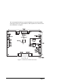
Figure 1. AC Receiver PCB connections
Page 5
Connections
Below is a description of each of the connectors. The connections are
described in numeric order, followed by video, network and power
connections.
CON1
CON1 is for the PCB power connection. This power controls the
switching of the relays, the video gain and lift and the lens functions. AC
power for the P/T head and auxiliaries is connected separately to CON5.
The PCB requires a +12V DC ± 10%, 1A class 2 power supply, this is
already connected.
Referring to figure 1 connect the +12V DC and 0V (return) to CON1.
If the polarity is correct when the power is switched on then LED1 (see
figure 1) is green. It appears red for an incorrect polarity.
CON2
If you are using a preset P/T head and lens then CON2 provides the
supplies and feedback (FB) connections for the pot-wiper circuits. The
direction of the feedback is automatically calculated when the test routine
is invoked (see Testing on page 9), this means it is not necessary to wire
the pots in a specific direction.
Referring to figure 1, connect CON2 to the preset pots on the P/T head
and the lens. Connect any unused feedback inputs to ground.
Make a note on your module description sheet of the preset connections
and the type of lens.
CON3
CON3 contains the lens drive outputs for focus, iris and zoom. The drive
voltage is +10V DC at up to 100 mA.
Refer to your lens instructions and connect up your lens according to
figure 1.
CON4
CON4 contains the power output connections for your P/T head and
auxiliaries (AUX A, AUX B, AUX C and AUX D).
Page 6
CAUTION : Your application must not draw more than 1A per relay or
it will damage your AC receiver
CAUTION : Connect lamps using a separate relay because they draw
an initial surge current which may damage your AC receiver
Referring to CON4 on figure 1 connect LEFT, RIGHT, UP and DOWN
to your P/T head and AUX A to wash, AUX B to wipe, AUX C to lamps
and AUX D to camera power. Do not connect any unused auxiliaries.
Connect all the return (neutral) wires to the spare terminals on the
external terminal block.
Make a note on your module description sheet of your auxiliary
connections.
CON5
CON5 accepts the AC power input which is switched to CON4 (pan, tilt
and auxiliaries). It powers the P/T head and auxiliaries.
WARNING : Never use both 24V AC and Mains on the same receiver
PCB.
For mains . . . Referring to figure 1 connect CON5 to the LIVE and
NEUTRAL connections on the external terminal block.
For 24V AC . . . Referring to figure 1 connect CON5 to the SUPPLY
and RETURN connections on the 24V AC power supply.
The middle connection on CON5 is Not Connected (NC).
CON6
CON6 is for an anti-tamper switch input. It is connected in parallel with
the anti-tamper switch shown on figure 1. The anti-tamper switch has a
spring fitted and so you cannot use CON6 (unless you first remove the
spring).
If you are not using the built in anti-tamper switch then connect CON6
on figure 1 to your anti-tamper switch in a N/C configuration.
VIDEO
All video must be via 75 ohm BNC connectors and video coaxial cable.
Your AC receiver has an on-board video amplifier with gain and lift.
Adjustment of gain and lift is done remotely, using a Pyramid keyboard.
Page 7
Referring to figure 1, connect the video from your camera to VIDEO IN,
through your AC receiver, then from VIDEO OUT to the matrix.
NETWORK
CAUTION : To avoid damaging your module switch off the power
before fitting the network card
Switch off the power, fit a network card in the position indicated on
figure 1.
Connect the cable provided from the network card to the filter board
mounted on the metal base plate.
Connect the network to the filter card. The wiring diagram is included on
the sheet provided with the network cards.
POWER
WARNING : Ensure that the power is switched off before connecting
the mains wires
WARNING : Your PY-ACW module must be earthed
Connect the Live, Earth and Neutral wires from the mains supply to Live,
Earth and Neutral on the external terminal block.
Check that all the wiring is correct and switch on the power.
WARNING : Your AC receiver PCB now contains live voltages
LED Power Indicator
LED1 (see figure 1) indicates the polarity of the 12V DC. For correct
polarity it is green, incorrect it is red.
Page 8
Testing
Your AC receiver has an on board test procedure which steps through
outputs in the sequence shown in Table 1. The test push button is shown
in figure 1. The test takes 55 seconds.
Running the test procedure also allows your receiver to detect the
feedback polarities for your P/T head and lens.
WARNING : Your AC receiver PCB now contains live voltages
Using an appropriate tool, press the test push button.
Table 1. The Automatic Test Sequence
Step
Action
Time
Step
Action
Time
1
Right & Down
5s
12
Zoom Out
3s
2
Pause
2s
13
Zoom In
3s
3
Pan Left
3s
14
Pause
2s
4
Pan Right
3s
15
Iris Close
3s
5
Pause
2s
16
Iris Open
3s
6
Tilt Up
3s
17
Pause
2s
7
Tilt Down
3s
18
AUX A
2s
8
Pause
2s
19
AUX B
2s
9
Focus Near
3s
20
AUX C
2s
10
Focus Far
3s
21
AUX D
2s
11
Pause
2s
22
Exit
Replacing the Lid
WARNING : Refit the lid securely to prevent unauthorised access
Tighten the four securing screws with an appropriate tool until they
cannot be undone by hand. Do not exceed a torque of 4 Nm.
Maintenance
Once your AC receiver is correctly installed and commissioned it
requires no routine maintenance.
Changing the Fuse
The fuse holder (see figure 1) contains a 10A A/S fuse for protecting the
relay outputs.
To replace the fuse, switch off all power to the module, turn the top anticlockwise using an appropriate tool, change the fuse and replace the top.
Page 9
Specifications
Features
Bar coding for ease of installation
Automatic configure and remote setup
Anti-tamper switch detects opening of lid, also external connection
provided.
All connections removable (except CON5, LIVE and NEUTRAL) screw
terminal blocks
128 Presets, all functions. Preset resolution, 10-bit
Random Pan / Patrol / Electronic end stops
Test button
Lens Drives
Zoom, focus and iris, 10V DC (max 100mA)
Network
Plug in network PCB, PY-FTT, PY-485, PY-422, PY-F17, PY-F19
Relays
P/T head relays
4 auxiliary relays for wash, wipe, lamps and camera power
Relay outputs Max 240 V at 1A
Fuse 10 Amp Anti-Surge
Video:
Via BNC connectors
Video 1V pk-pk PAL/NTSC
Max Gain >5dB
Max Lift >4dB at 4MHz
Power
Board Power 12V DC ± 10%, 1A class 2
Relay Power max 240V AC, 10A
Nominal Consumption 8.5 Watts (12V DC)
Physical
Weight 5 kg
PCB Weight 0.5kg
Page 10
IP65 case
Board size 130 x 160 x 40mm (excluding mounting pillars)
Box Size 280 x280 x130mm
Temperature Specification
Operational temperature limits:-10ºC to +50ºC at 10% to 80% relative humidity (non-condensing)
Storage temperature limits:-20ºC to +60ºCat 10% to 95% relative humidity (non-condensing)
Page 11
%D[DOO6HFXULW\/LPLWHG
Stockport, England
Baxall Security Ltd. Reserve the right to make changes to the product and
specification of the product without prior notice to the customer.
HBPYAC
Issue 1 : 12/95