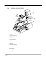
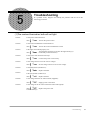
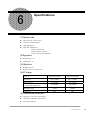
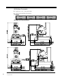
1
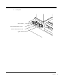
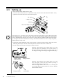
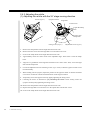
MANUAL No.4769AԘ SERIES No.176 TM-500 Series TOOLMAKER’S MICROSCOPE User s Manual㩷 ’ Read this User's Manual thoroughly before operating the instrument. After reading, retain it close at hand for future reference.㩷 PREFACE Thank you for purchasing the Mitutoyo TM-500 series Measuring Microscope. 䃂This User's Manual explains the hardware operations of the Mitutoyo TM-500 series and the precautions to be observed during operation. To obtain the best possible performance and longest service life from your TM-500 series Measuring Micro-scope, please read this user's manual thoroughly. Be sure to read PRECAUTIONS before using this Measuring Microscope. 䃂After reading this user's manual retain it for future reference. CONVENTIONS USED IN THIS MANUAL The following visual cues are used throughout this manual to identify different types of information: Indicates that the operator should exercise care to avoid danger of fire, explosion, or personal injury. DANGER Indicates that operating the instrument in this manner may damage it or may cause it to malfunction. 㩷 CAUTION㩷 Draws attention to important information, recommended operation techniques, or helpful tips. Gives reference location for further information on topic. 㩷 Highlights installation, measurement, or other procedures. 㩷㩷㩷 PREFACE /CONVENTIONS USED IN THIS MANUAL i PRECAUTIONS (1) Relocation 䃂The Measuring Microscope is a precision instrument. Handle it with care when transporting/relocating. Do not touch the movable members, which must be secured, during transportation. 䃂Place a cushioning pad between the Micrometer Head and the XY stage, as shown below, to prevent the Micrometer Head spindle from hitting the table. Cushioning pad (2) Installation Install the TM-500 in a site with: 䃂 as little dirt, dust, and humidity as possible. Put the supplied dust cover on it if it is not going to be used for an extended period of time. 䃂no vibrations. 䃂no sudden temperature changes, which may result if the site is subjected to direct sunlight. (3) Explosive Hazard 䃂Do not operate the Measuring Microscope in the presence of explosive gas. (4) Power Supply 䃂Depending on the installation site, voltage fluctuation may cause a change in light intensity or flickering of the illumination bulb. Although this does not affect measurement, use a voltage stabilizer if a stable light intensity is required. 䃂Use an AC power supply which is isolated from high-voltage, large-current machinery. High-voltage, large-current machinery often emits a substantial amount of electric noise due to surge currents, which can adversely affect this measuring system if it draws power from an AC outlet often provided on such equipment. Therefore, the Measuring Microscope should draw power from a separate outlet. The power cable of the Measuring Microscope should run as far apart as possible from such noise sources. ii PRECAUTIONS 䃂Only use the power cord that is supplied with the instrument. For a replacement power cord, contact Mitutoyo. 䃂Only use the supplied replacement fuse or a fuse with identical specifications (type, nominal voltage and current). (5) Ground Positively 䃂Ground the Measuring Microscope positively, especially if it must be installed near equipment emitting substantial amounts of electric noise. To do this connect the grounding wire from the Measuring Microscope to the body of a piece of equipment, which also must be grounded. The grounding wire should be as short as possible and should not be wound into a loop or coil. (6) Do Not Disassemble 㩷 䃂There are high-voltages inside the Measuring Microscope. Do not attempt to disassemble it unless otherwise specified. WARRANTY In the event that the Mitutoyo Measuring Microscope TM-500 series should prove defective in workmanship or material, within one year from date of purchase for use, it will be repaired or replaced, at our option, free of charge upon its prepaid return to us. PRECAUTIONS/WARRANTY iii CONTENTS㩷 PREFACE........................................................................................................................... γ CONVENTIONS USED IN THIS MANUAL ................................................................... γ PRECAUTIONS................................................................................................................. δ WARRANTY ..................................................................................................................... ε 1. Outline .............................................................................................................................. 7 1.1 Description.............................................................................................................. 7 1. 2 Name of Each Part ................................................................................................. 8 2. Installation and Setup ..................................................................................................... 11 2.1 Package Contents .................................................................................................. 11 2.2 Installation Site ..................................................................................................... 11 2.3 Setting-up.............................................................................................................. 12 2.4 Checking and Adjustment..................................................................................... 13 2.4.1 Checking the reticle position against the XY stage movement direction .. 13 2.4.2 Checking the centering of the reticle ......................................................... 13 2.4.3 Adjusting the reticle ................................................................................... 14 3. Measurement .................................................................................................................. 17 3.1 Preparations for Measurement .............................................................................. 17 3.1.1 Precautions for measurement ..................................................................... 17 3.1.2 Replacing the lenses................................................................................... 18 3.1.3 Fixing the workpiece.................................................................................. 18 3.1.4 Illumination modes..................................................................................... 19 3.1.5 Replacing reticles ....................................................................................... 20 3.1.6 Adjusting the diopter.................................................................................. 20 3.1.7 Bringing the measuring surface into focus................................................. 21 3.1.8 Positioning the workpiece .......................................................................... 21 iv CONTENTS 3.2 Measurement......................................................................................................... 22 3.2.1 Dimensional measurement ......................................................................... 22 3.2.2 Angle measurement.................................................................................... 23 3.2.3 Template matching inspection ................................................................... 24 3.2.4 Step measurement ...................................................................................... 24 4. Maintenance ................................................................................................................... 25 4.1 Cleaning and Lubrication...................................................................................... 25 4.2 Inspection.............................................................................................................. 25 4.3 Replacing Consumable Parts ................................................................................ 27 4.4 Consumable Parts.................................................................................................. 29 5. Troubleshooting.............................................................................................................. 31 6. Specifications ................................................................................................................. 35 7. Optional Accessories ...................................................................................................... 37 8. Reference Diagrams...................................................................................................... 39 SERVICE NETWORK....................................................................................................... 41 CONTENTS v vi CONTENTS 㪈 1.1 Description Outline㩷 This chapter outlines the Mitutoyo Toolmaker’s Microscope TM-500 series and gives the name of each part. The Mitutoyo Toolmaker’s Microscope TM-500 series (TM- 505 and TM-510) are easy-to-use, compact-size Toolmaker’s Microscopes that feature a vertical supporting column. Designed with measurement of workpiece contours and inspection of surface features in mind, the TM-500 series supports a wide range of applications from shop-floor inspection, measurement of tools and machined parts, to precision measurement of test tools in a measuring room. z A long vertical working distance (67mm) and erecting image have improved operability. z The XY stage is mounted on a compact body to support wide travel ranges (50mm㬍50mm for TM-505, 100mm㬍50mm for TM-510) for effective measurement. z Fine/coarse focusing can be performed with a single focusing knob. z The angle dial built into the eyepiece portion of the optical tube allows easy angle measurement. 1. Outline 7 1.2 Name of Each Part 8 1 9 2 3 10 11 4 12 5 13 6 14 7 1. Eyepiece 2. Diopter adjustment ring 3. Eyepiece mount 4. Optical tube 5. Surface illuminator 6. Objective 7. XY stage 8. Angle dial 9. Angle dial clamp screw 10.Vernier 11.Vernier clamp screw 12.Focusing knob 13.Control panel 14.Power panel 8 1. Outline 13. Control panel Power switch Contour illumination switch Surface illumination switch Light control knob 1. Outline 9 14. Power panel (for standard model) Surface illuminator cable connector GND terminal The voltage setting method display AC inlet Fuse holder Voltage selector Power panel (for CE correspondences) AC inlet Fuse holder Surface illuminator cable connector Voltage selector 10 1. Outline GND terminal 㪉 2.1 Package Contents Installation and Setup㩷 This chapter lists the contents of the TM-500 series package and describes the setup and adjustment procedures. Standard accessories Name 1. TM-505R TM-510 TM-510R 176-138 1 1 1 1 2. Eyepiece㧔15㧕 176-116 1 1 1 1 3. Lens cap 1 1 1 1 4. Cross-hair line reticle 1 1 1 1 5. Surface illuminator 1 1 1 1 6. Micrometer Head 㧙 2 㧙 2 7. Mounting screw 㧙 㧙 2* 2* 8. Reticle setting screw 200624 1 1 1 1 9. Bulb setter 1 1 1 1 10. Allen key nominal 3 1 1 1 1 11. Vinyl cover 1 1 1 1 12. Spare bulb 㧔24V㧕 1 1 1 1 13. Objective㧔2㧕 511187 176-126 380597 511188 538616 512555 383038 Spare fuse㧔1A㧕not CE 350279 1 1 1 1 Spare fuse㧔1A㧕for CE 384204 1 1 1 1 14. Power cord 1 1 1 1 15. Grounding wire 1 1 1 1 16. User’s Manual 1 1 1 1 17. 2.2 TM-505 Warranty 1 1 1 1 *㧦Keep the mounting screws in the TM-510/510R package. They are provided to install the optional mounting jigs on the XY stage. Installation Site Install the Measuring Microscope in a place which is free from vibration and dust. Exposing the instrument to vibrations over long periods of time can deteriorate its measuring accuracy. Dust adversely affects the optical parts, the XY stage, and moving parts. 2. Installation and setup 11 2.3 Setting-up 1. Install the Micrometer Head on the XY stage. Loosen the hex-socket head screw on the bracket. Fully insert the stem of the Micrometer Head . Then, tighten the hex-socket head screw with the stem in place. XY stage Clamp screw Bracket Hex-socket head screw The clamp screw is provided to secure the spindle of the Micrometer Head. If using a Micrometer Head with a fitting hole in the stem, insert the stem so the hole is aligned with the clamp screw. If this puts the scale on the Micrometer head in a poor position for viewing the zero graduation, adjust the scale position by turning the Micrometer Head sleeve. If using a Micrometer Head with no hole to clamp the spindle, lightly tighten the clamp screw. 2. Connect the surface illuminator cable to the connector on the power panel, which is at the back of the Measuring Microscope. Insert the cable firmly into the connector and secure it with the nut. 3. Set the voltage selector plug to the supply voltage as follows. When the voltage selector on the back panel is as in the upper left figure, the combination of two slide switches on the upper and lower sides performs a voltage setup. Set up the voltage according to the voltage setting method display. Voltage setting method display. Voltage selector When the voltage selector on the back panel is as in the lower left figure, remove the fuse holder by turning it counterclockwise using a screw driver. Turn the voltage selector with a coin, etc., and align the rated voltage display with the position of the arrow. Replace the fuse holder as before. Voltage selector 12 2. Installation and setup Fuse holder 2.4 Checking and Adjustment 2.4.1 Checking the reticle position against the XY stage movement direction 1䋮 Place a small workpiece on the stage glass and bring it into focus. 2䋮 Turn the Micrometer Heads to align an edge of the workpiece with the center of the cross-hair. 3䋮 While turning the Micrometer Head to move the workpiece left and right, turn the angle dial so that the horizontal cross-hair is oriented to coincide with the direction of the stage movement. Small workpiece 㪋㪅 Loosen the vernier clamp screw. Align the “0” graduation on the angle dial with that of the vernier scale. Ensure the margin is sufficient for adjusting the vernier scale position. If space for adjusting the vernier scale position is limited, re-adjust the vernier scale position by referring to "2.4.3 (1) Adjusting the reticle to the XY stage movement direction".㩷 㩷 2.4.2 Checking the centering of the reticle㩷 To perform dimensional measurement by turning the angle dial or after replacing the reticle, align the cross-hair with the center of rotation of the angle dial, as follows.㩷 1䋮 Place a small workpiece on the stage glass and bring it into focus. 2䋮 Turn the Micrometer Heads to align an edge of the workpiece with the center of the cross-hair. 3䋮 Turn the angle dial 180q. Make sure the edge of the workpiece remains within 3μm of the center of the cross-hair. If it is not within 3μm, adjust the center of the reticle by referring to "2.4.3 (2) Centering the reticle". 2. Installation and setup 13 2.4.3 Adjusting the reticle㩷 (1) Adjusting the reticle with the XY stage moving direction㩷 㩷 Angle dial cover Screws (4 pcs.) Eyepiece mount Angle dial Vernier scale Angle dial clamp knob Vernier scale clamp knob Fixing screws (4 pcs.) 㩷㩷㩷㩷㩷 Adjustment screws (4 pcs.) 㩷 㩷 㪈䋮 Remove the clamp knobs from the angle dial and vernier scale.㩷 㪉䋮 Remove the four screws from the angle dial cover and remove the cover.㩷 3㧚 Screw-in the clamp knobs on the angle dial and vernier scale. 4㧚 Approximately center the vernier scale in the adjustable range. Then secure it with the clamp knob. 5㧚 Align the “0” graduation of the angle dial with that on the vernier scale. Then, secure the angle dial with the clamp knob. 6㧚 Loosen the adjustment screws and fixing screws (4 pcs. each) so that the eyepiece mount can be moved manually. 㪎䋮 While looking into the eyepiece, adjust the position of the eyepiece mount so that the horizontal cross-hair is oriented to coincide with the direction of the stage movement.㩷 8㧚 Temporarily secure the eyepiece mount by lightly tightening the fixing screws. 㪐䋮 Centering the reticle as described in "(2) Centering the reticle" below. Firmly secure the eyepiece mount by fully tightening the fixing screws.㩷 㪈㪇䋮Remove the clamp knobs from the angle dial and vernier scale.㩷 㪈㪈䋮Replace the angle dial cover and secure it to the optical tube with the four screws.㩷 㪈㪉䋮Screw-in the clamp knobs on the angle dial and vernier scale.㩷 14 2. Installation and setup (2) Centering the reticle 1䋮 Place a small workpiece on the stage glass. Turn the Micrometer Heads to align an edge of the workpiece with the center of the cross-hair. 2䋮 Rotate the angle scale disc 180q and read the displacement between the edge of the workpiece and the center of the cross-hair. 3䋮 Remove the four screws from the angle dial cover and dismount it. Slightly loosen the four fixing screws. 4䋮 Adjust the eyepiece mount position with the four adjustment screws to minimize the displacement between the edge of the workpiece and the center of the cross-hair. Centering is easily performed by moving the eyepiece mount by half the displacement in both the X and Y directions. Two pairs of adjustment screws are located at the opposite sides (for adjusting the X and Y displacements). Adjust the screws in pairs. Loosen one on one side, and then tighten its counterpart on the other side to adjust the displacement. 5䋮 Turn the Micrometer Heads to align an edge of the workpiece with the center of the cross-hair. Rotate the angle dial 180q and check the displacement. 6䋮 Repeat steps 1, 2, 4, 5 until the displacement is within 3μm. 7䋮 Confirm that the four adjustment screws are fully tightened. 8䋮 Tighten the four fixing screws and replace the angle dial cover. 1㧚 2㧚 4㧚 Small workpiece 2. Installation and setup 15 16 2. Installation and setup Measurement㩷 㪊 This chapter describes the preparations for measurement and the measuring procedures. 3.1 Preparations for Measurement 3.1.1Precautions for measurement z Installation site When selecting an installation site, take vibration, dust and humidity into due consideration. Vibration can affect measuring accuracy. Dust and humidity can impair optical parts, such as the objective and prism, and the XY stage and moving parts. z Precaution for operation If focusing, making measurements, or mounting work pieces, take surrounding conditions into account. Be careful not to bump the objective, stage glass, etc. z Objective and Eyepiece The supplied objective and eyepiece were finely adjusted before shipment. To maintain performance and accuracy, handle them with care and do not disassemble. Do not allow the surface of the lens to be scratched or to be exposed to machine oil. If the lens is soiled, clean it as described in “4.1 Dusting and Applying Oil”. z Stage glass Since workpieces are mounted on it, the stage glass is likely to be scratched or even severely damaged. Dust the workpiece before placing it on the stage glass. Exercise care so as not to bump the stage glass with the workpiece. Do not slide the workpiece on the stage. 3. Measurement 17 3.1.2 Replacing the lenses An objective (2x) and an eyepiece (15x) are provided with a total magnification of 30x. 1䋮 The following objectives and eyepieces are available as optional accessories. z Eyepiece (10x, 20x) z 5x Objective (working distance: 33mm), 10x Objective (working distance: 14mm) 2. To mount the eyepiece, insert it into the eyepiece mount. The objective can be screwed into the optical tube. Before dismounting the objective, remove the fixture clamping down the surface illuminator from 㩷 the objective. The fixture is attached to the objective. The O-ring is between the fixture and the objective. Pull down the fixture by gently swinging it back and forth. 3.1.3 Fixing the workpiece Once the workpiece is mounted, secure it to the stage glass. Use the fixing jigs secured to the T-groove on the XY stage if required. The workpiece must be positioned so that the measuring surface faces the objective.䇯 The following optional fixing jigs are available. 1. Swivel center support (No.176-105 for TM-505/505R, 172-197 for TM-510/510R) Used to secure cylindrical workpieces (with center hole) and screws. 2. V-block (No.172-378) Used to mount cylindrical workpieces (without center hole). 3. Holder with clamp (No.176-107) Used to mount thin flat workpieces. 4. Chart clip (for XY stage) No.990561 (for TM-505/505R) Used to mount thin flat workpieces (securing to the T-grooves on the XY stage). Swivel center support No.176-105 No.172-197 V-block No.172-378 Chart clip䋨for XY stage䋩 No.990561 18 3. Measurement Holder with clamp No.176-107 3.1.4 Illumination modes The TM-500 series supports the following illumination modes. Select appropriate illumination mode according to your application. (1) Contour illumination The contour illumination generates the contour image of a workpiece, and is suited for measurement and inspection of workpiece contours. The illuminator is equipped with a green filter. (2) Surface illumination Surface illumination shows the surface of a workpiece, and is used in observation and inspection of workpiece surfaces. Adjust the angle and orientation of this illuminator so the workpiece surface can be observed under optimum conditions. (3) Simultaneous use of contour and surface illuminations Both the contour and surface of a workpiece can be observed simultaneously. Power switch Contour illumination switch Surface illumination switch Light control knob 3. Measurement 19 3.1.5 Replacing reticles To replace reticles, use the supplied reticle setting screw, as described below. 1. Pull up and remove the eyepiece. 2. Screw the reticle setting screw into the reticle. Pull out the reticle setting screw along with the reticle. 3. Screw the reticle setting screw into the reticle to be mounted. Insert the reticle into the eyepiece mount. The reticle is provided with a positioning pin. Fit the pin in the groove on the eyepiece mount and insert the eyepiece as far as possible. 4. Remove the reticle setting screw and insert the eyepiece. Reticle setting screw Reticle setting screw Reticle Reticle Positioning pin Positioning pin 3.1.6 Adjusting the diopter While looking into the eyepiece, turn the diopter adjustment ring until the reticle can be seen sharply. Diopter adjustment ring Focusing knob 20 3. Measurement 3.1.7 Bringing the measuring surface into focus Bring the measuring surface into focus by moving the optical tube up and down with the focusing knob. Look into the eyepiece to make sure the cross-hairs are kept in ocular focus during this focusing operation. If moving the optical tube, be careful, especially if the workpiece is stepped or is secured with fixing jigs, not to bump the workpiece. CAUTION 3.1.8 Positioning the workpiece Align the measuring direction of the workpiece with the traversing direction of the stage. 䋨䋱䋩Follow the procedure in "2.4.3 (1) Adjusting the reticle with the XY stage moving direction". 䋨䋱䋩Move the workpiece or the fixing jigs to align the measuring direction of the workpiece with the cross-hair reticle. After making the above adjustment, confirm that the workpiece is parallel with the traveling direction by moving the XY stage. 3. Measurement 21 3.2 Measurement 3.2.1 Dimensional measurement Align a measuring point on the workpiece with one of the cross-hairs and take the reading from the Micrometer Head. Then, move the XY stage by turning the Micrometer Head and align another measuring point with the same cross-hair and take the reading at this point. The difference between the two readings represents the dimension between the two measuring points. A Digimatic Head and Digital Counter can be used, in place of the Micrometer Head, for digital display of the displacement. They also eliminate reading errors. Since the zero-set button zeroes the counter at any position, the displacement can be read directly. 22 3. Measurement 3.2.2 Angle measurement Angles are measured with the angle dial, using either of the following two procedures. (1) (2) (1) Align an edge of the workpiece with the cross-hair reticle and align the end edge with the center of the cross-hair. Turn the angle dial to align the cross-hair with the other edge of the workpiece. Take readings from the angle dial. (2) Align two edges of the workpiece with the same cross-hair, one after another, by turning the angle dial and moving the XY stage. Take readings from the angle dial.㩷 1䋮In both procedures, measuring points on the workpiece are aligned with a cross-hair, one after another. The angle is determined from the difference in readings. 2䋮The resolution of the angle dial is 1q with the main scale and 6' with the vernier scale. 㩷 㩷 㩷 㩷 㩷 <Reading the angle dial> Main scale䋺34¡ 34¡42㶅 Vernier scale䋺42㶅 3䋮The zero position of the angle dial can be adjusted by turning the vernier scale. This allows the angle measurement origin to be set to 0. After turning the vernier scale, check the reticle position. Refer to "2.4.3 (1) Adjusting the reticle against the XY stage moving direction" if necessary. CAUTION 3. Measurement 23 3.2.3 Template matching inspection This Measuring Microscope allows inspection of screw threads and involute gear teeth using the optional template reticles. To perform template matching inspection, set the appropriate optional template reticle according to 㩷 the procedure in "3.1.5 Replacing the reticle". For information about the various template reticles, see "7. Optional Accessories". 3.2.4 Step measurement Stepped dimensions can be measured using the optional height measurement attachment and a dial indicator. This measurement is performed by bringing the measuring faces in focus. A high-precision measurement cannot be made if using a lens with a large depth of focus. To obtain high-accuracy CAUTION measurements, use a high-magnification lens with a shallow depth of focus, as shown below. 䃂30x lens with a depth of focus of approximate 0.12mm 䃂150x lens with a depth of focus of approximate 0.02mm Attach the height measurement attachment to the top face of the column as shown in the figure below. Use a gauge block that is appropriate for the optical tube position. Dial indicator Mounting screw Height measurement attachment Gauge block Column 24 3. Measurement 㪋 Maintenance This chapter describes the daily and periodical inspection and maintenance required to maintain the performance of this microscope. 4.1 Cleaning and Lubrication (1) Main unit Periodically apply a thin layer of grease over the slide guide surfaces and rack of the optical tube using a brush. (2) XY stage Apply a thin layer of spindle oil to guide rails. After dusting the stage glass wipe it gently with a soft cloth. (3) Eyepiece and objective Since the optical glass used for lenses is soft and subject to scratches, always use an air-blower or a feather to dust the lens surface. To remove contaminants such as oil and fingerprints, gently wipe them in a circular motion with gauze dampened in high-grade alcohol. 4.2 Inspection To maintain this microscope in prime condition, periodically inspect the parts specified below. If the microscope is not operating perfectly, inspect it in detail according to the procedure in “5. Troubleshooting”. (1)Connecting parts Turn off the power switch and pull out the power cord from the AC outlet to prevent electric shocks. DANGER z Check the power cord, input connector (AC inlet), voltage selector, GND terminal, surface illuminator connector, and other joints for looseness and poor connections. (2)Power and illumination switch and light control knob z Check the power switch z Check that the contour and surface illuminators light by turning on the illumination switch. z Check that the light intensity of each illuminator changes by turning on the light control knob. 4. Maintenance 25 (3)Focusing knob z Check this knob for any abnormal tightness, play, unevenness, and sound. (4)XY stage z Check the stage glass for scratches and contaminants. z Move the XY stage over the measuring range by hand to check for any abnormal tightness, play, unevenness, and sound. (Perform the same cheek on the stage by turning the micrometer heads.) (5)Angle dial z Loosen the angle dial clamp knob and turn the dial to check for any abnormal tightness, play, unevenness, and sound. (6)Field of view z Look into the eyepiece under contour illumination and check the entire filed of view for vignetting and uneven illumination. (7)XY stage feeding accuracy z This inspection will be affected by the measuring environment, alignment error, and other adverse conditions. Keeping these factors in mind, check the feeding accuracy by measuring a workpiece or a standard scale with an appropriate dimension of 5mm. 1. Position a workpiece, for which accurate dimensions are known, on the stage glass and bring it into focus. 2. Align a measuring point on the workpiece with one of the cross-hairs, according to the moving direction of the workpiece. 3. Obtain the dimension from the readings on the Micrometer Head. Refer to “3.2.1 Dimensional measurement”. 4. Measure the X- and Y-axis dimensions of the workpiece. If the difference between the measured and nominal dimensions is less than 5Ǵm (for any 5mm travel range), the XY stage feeding accuracy is adequate. (8)Resolution z Position a workpiece on the XY stage and bring it into focus. Check if any region of the image in the field of view has poor resolution. 26 4. Maintenance 4.3 Replacing Consumable Parts (1) Replacing the fuse When a fuse holder is as in the upper left figure 1. Turn off the contour and surface illumination switches and the power switch, and the pull out the power cord. 2. Insert a screwdriver in the rectangular hole of the fuse holder and raise the screwdriver grip, then a latch will separate and the fuse holder will come out from the front. 3. Replace the fuse, and replace the fuse holder. When a fuse holder is as in the lower left figure 1. Turn off the contour and surface illuminator switches and the power switch and pull out the power cord. 2. Insert a screwdriver in the rectangular hole on the fuse holder and turn it counterclockwise, then a latch will separate and a fuse holder will come out from the front. 3. Replace the fuse, and replace the fuse holder. (2)Replacing the stage glass 1. While pushing the stage glass in the direction of the leaf spring, raise the glass at the front edge, and then remove it. 2. Attach the leaf spring in place and mount new stage glass. Leaf spring Stage glass Since the stage glass is pushed forward with the leaf spring, when you remove the stage glass, be 㩷 CAUTION careful not to lose the leaf spring. 4. Maintenance 27 (3)Replacing the contour illumination bulb The bulb remains hot after it has been turned off. Do not replace the bulb until it had cooled down. 㩷 CAUTION㩷 1. Turn off the contour illumination switch and power switch. 2. Remove the stage glass. (See (2) above.) 3. Turn the green filter counterclockwise to remove it. 4. Remove the bulb by turning it counterclockwise with the supplied bulb setter. 5. Mount a new bulb using the bulb setter. 6. Turn on the power switch and contour illumination switch. Check that the bulb lights. 7. Replace the green filter and the stage glass, in this order. 28 4. Maintenance (4)Replacing the surface illumination bulb The bulb remains hot after it has been turned off. Do not replace the bulb until it has cooled down. 㩷 CAUTION㩷 1. Turn off the surface illumination switch and power switch. 2. Turn the white filter counterclockwise to remove it. 3. Remove the bulb by turning it counterclockwise with the supplied bulb setter. Mount a new bulb using the bulb setter. 4. Switch the illuminator select switch knob to the surface illumination. 5. Check that the bulb lights. 6. Turn on the power switch and surface illumination switch. Check that the bulb lights. 7. Replace the white filter. 4.3 Consumable Parts Order No. Name 380405 Stage glass 96x96 (for TM-505/505R) 380495 Stage glass 154x96 (for TM-510/510R) 512555 Vinyl cover 383038 Illumination bulb (24V) 350279 Fuse (1A) for other than CE 384204 Fuse (1A) for CE 380240 Leaf spring 4. Maintenance 29 30 4. Maintenance Troubleshooting 㪌 If a problem occurs, diagnose and remedy the problem with the aid of the following procedures. (1)The contour illumination bulb will not light. Check1䋺 Is the power switch turned on? YES Check2䋺 No Turn on the power switch. Is the contour illumination switch turned on? YES No Turn on the contour illumination switch. Check3䋺 Is the light control knob properly set? Turn the knob clockwise to increase the light intensity (if YES No turned fully counterclockwise). Check4䋺 Is the power cord connected correctly? YES Check5䋺 No Replace the bulb. No Replace the fuse. Is the voltage from the AC outlet normal (supplied)? YES Check9䋺 Set the voltage selector to the correct voltage. Is the fuse normal (conductive)? YES Check8䋺 No Is the bulb normal (conductive)? YES Check7䋺 Connect the power cord correctly. Is the voltage selector set to the correct voltage? YES Check6䋺 No No Supply power to the outlet. Is the voltage at the AC inlet on the main unit normal (input)? YES No Replace the power cord. Contact Mitutoyo. 5. Troubleshooting 31 㩿㪉㪀The surface illumination bulb will not light. Check1䋺 Is the power switch turned on? YES Check2䋺 No Turn on the power switch. Is the surface illumination switch turned on? YES No Turn on the surface illumination switch. Check3䋺 Is the light control knob properly set? Turn the knob clockwise to increase the light intensity (if YES No turned fully counterclockwise). Check4䋺 Is the power cord connected correctly? YES Check5䋺 No Replace the bulb. No Replace the fuse. Is the voltage from the AC outlet normal (supplied)? YES Check9䋺 Set the voltage selector to the correct voltage. Is the fuse normal (conductive)? YES Check8䋺 No Is the bulb normal (conductive)? YES Check7䋺 Connect the power cord correctly. Is the voltage selector set to the correct voltage? YES Check6䋺 No No Supply power to the outlet. Is the voltage at the AC inlet on the main unit normal (input)? YES No Replace the power cord. Contact Mitutoyo. (3)The light intensity of contour illumination cannot be adjusted (if the contour illumination switch is turn on ). Check䋺 32 5. Troubleshooting Is the contour illumination bulb lit? Refer to "(1) The contour illumination bulb will not light". YES No Contact Mitutoyo. (4)The light intensity of surface illumination cannot be adjusted (if the surface illumination switch is turn on ). Check䋺 Is the surface illumination bulb lit? Refer to "(2) The surface illumination bulb will not light". YES No Contact Mitutoyo. (5)The optical tube will not move up and down properly. If there is any abnormal tightness, play, unevenness, or sound when the optical tube is moved, contact Mitutoyo. Should this be the case, do not continue to move the optical tube or disassemble it. (6)The angle dial will not rotate properly. If there is any abnormal tightness, play, unevenness, or sound when the optical tube is moved, contact Mitutoyo. Should this be the case, do not continue to move the optical tube or disassemble it. (7)The XY stage will not properly be fed. If there is any abnormal tightness, play, unevenness, or sound when the XY stage is fed, contact Mitutoyo. Should this be the case, do not continue to feed the XY stage or disassemble it. If the feeding accuracy has deteriorated, determine whether the stage or the Micrometer Head is the problem and contact Mitutoyo. (8)There is a shadow in the field of view. Check for: z Obstruction between the contour illumination bulb and the objective . z Contaminated reticle. z Contaminated objective or eyepiece. If the problem cannot be rectified, contact Mitutoyo. (9)The resolution in a region of the field of view is poor. Check for: z Poor focusing (because of a stepped workpiece). z Oil soiling the workpiece. z Improperly mounted objective or eyepiece. z Contaminated or damaged (such as scratch) objective or eyepiece. z Contaminated or damaged (such as scratch) reticle. If the problem cannot be rectified, contact Mitutoyo. 5. Troubleshooting 33 34 5. Troubleshooting 㪍 Specifications (1)Optical tube z Optical axis:30qfrom vertical z Cross-hair reticule supplied z Adjustable diopter z Angle dial: Graduation 1q Angle of rotation 360q Angle reading 6’ (vernier) Vernier zero position adjustable (2)Eyepiece z Magnification :15 z Field number :13 (3)Objective z Magnification :2 z Working distance :67mm (2.63”) (4)XY stage Order No. Dimensions Stage glass size Feeding range 㧔if used with gauge block㧕 Maximum height workpiece TM-505/TM-505R TM-510/TM-510R 152152mm 240152mm 9696mm 15496mm 5050mm 10050mm 115mm 107mm 5Kg 5Kg (5)Transmitted illuminator z Light source :24V, 2W (special bulb) z Continuously adjustable light intensity z Green filter supplied 6. Specifications 35 (6)Surface illuminator z Light source : 24V㧘2W (special bulb) z Continuously adjustable light intensity (7)Mass TM-505 TM-505R TM-510 TM-510R 13.5Kg 14.0Kg 14.5Kg 15.0Kg (8)Main unit dimensions 36 6. Specifications 㪎 Order No. Optional Accessories Name 176-105 Swivel-center support㧔for TM-505/TM-505R㧕 172-197 Swivel-center support 㧔for TM-510/TM-510R㧕 176-106 Rotary table㧔for TM-505/TM-505R㧕 172-196 Rotary table 㧔for TM-510/TM-510R㧕 176-107 Holder with clamp 172-378 V-block with clamp 176-203 Twin-bulb surface illumination unit 176-204 Height measurement attachment 176-115 Eyepiece 10 176-117 Eyepiece 20 176-137 Objective 10 176-139 Objective 5 176-109 Reticle (Template) Metric screw p=0.25㨪1.0 176-110 Reticle (Template) Metric screw p=1.25㨪2.0 176-111 Reticle (Template) Concentric circles Ǿ0.05㨪4.00mm 176-113 Reticle (Template) Involute gear tooth m0.1㨪1.0, pressure angle 20q reference rack Reticle (Template) 55qangle line 176-114 Reticle (Template) 60qangle line 176-120 Reticle (Template) Whiworth screw thread (inch) 60㨪26TPI 176-121 Reticle (Template) Whiworth screw thread (inch) 24㨪18TPI 176-122 Reticle (Template) Whiworth screw thread (inch) 16㨪11TPI 176-123 Reticle (Template) Unified screw thread 80㨪28TPI 176-124 Reticle (Template) Unified screw thread 24㨪14TPI 176-125 Reticle (Template) Unified screw thread 13㨪10TPI 176-112 7. Optional Accessories 37 176-127 Reticle (Template) Unified screw thread NF80㨪28TPI 176-128 Reticle (Template) Unified screw thread NF24㨪14TPI 176-129 Reticle (Template) Unified screw thread NF13㨪10TPI 176-130 Reticle (Template) Involute gear tooth m0.1㨪1.0 pressure 14” 30’ , reference rack 176-135 Reticle (Template) Concentric circles Ǿ.01” pitch, maximum diameter Ǿ.2” 176-140 Reticle (Template) ISO metric screw thread p=0.075㨪0.7 176-141 Reticle (Template) ISO metric screw thread p=0.75㨪2.0 176-142 Reticle (Template) ISO unified screw thread 80㨪28TPI 176-143 Reticle (Template) ISO unified screw thread 24㨪14TPI 176-144 Reticle (Template) ISO unified screw thread 13㨪10TPI 990561 Chart clip (for XY stage) 176-366̪ Fiber-optic circular illumination unit 176-344̪ Twin fiber optics illumination unit, twin fiber-optic illuminator 264-140̪ 164-161 164-162 ٌ 2D data processing unit QM-Data200 ً Digimatic micrometer head MHD-50M Digimatic micrometer head MHD-2̢M 937387 ً Connecting cable (1m): connect between MHD-50M and MUX-10F 965013 ً Connecting cable (2m): connect between MHD-50M and MUX-10F 264-002 ً MUX-10F ً Connecting cable C: connect between MUX-10F and QM-Data200 ̪: The order number differs depending on the shipping destination. ٌ: When using QM-Data200 it also requires MDH-50M (2 units), connecting cables (2 pcs of either length), MUX-10F and connecting cable C. 12AAD194 38 7. Optional Accessories 㪏 Reference Diagrams Top view of XY stage TM-505/505R Detail drawing of T-groove 8. Reference Diagrams 39 TM-510/510R Detail drawing of T-groove 40 8. Reference Diagrams