1
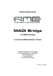
User's Guide
MADI Bridge
The MADI Patchbay
8 x 64 Channel MADI Switcher / Router
6 coaxial Inputs and Outputs
2 optical Inputs and Outputs
MIDI Remote Control
Preset Memory
64 Dot Matrix Display
Firmware 1.1 or up
Important Safety Instructions ..................................3
1
2
3
4
5
Introduction ...............................................................4
Package Contents .....................................................4
Brief Description and Characteristics.....................4
Firmware ....................................................................4
Technical Specifications ..........................................5
5.1 Inputs .........................................................................5
5.2 Outputs ......................................................................5
6
First Usage
6.1 Quick Start .................................................................6
6.2 Operation ...................................................................7
7
Inputs and Outputs
7.1 MADI Inputs ...............................................................8
7.2 MADI Outputs ............................................................8
7.3 MIDI Input and Output ...............................................8
8
Software MIDI Remote
8.1 MIDI Control of the MADI Bridge ...............................9
8.2 General Notes on Operation ......................................9
8.3 Brief Description of the menu entries.......................10
9
Configuration Examples
9.1 Distribution 1 to 8 .....................................................11
9.2 Pass On Mode .........................................................11
9.3 Conversion Optical to Coaxial and vice versa .........11
10
Technical Background
10.1
MADI Basics......................................................12
10.2
MADI Bridge Technology ..................................13
10.3
Inputs 5/6 Compatibility Mode (Sony 3348) ......13
11
Controls and Connectors .......................................14
12
Block Diagram .........................................................15
13
MIDI Implementation Chart
13.1
Basic SysEx Format ..........................................16
13.2
Message Types .................................................16
13.3
Total Reset ........................................................16
13.4
Table..................................................................17
14
Warranty...................................................................20
15
Appendix ..................................................................20
2
User's Guide MADI Bridge © RME
Important Safety Instructions
ATTENTION! Do not open chassis – risk of electric shock
The unit has non-isolated live parts inside. No user serviceable parts inside.
Refer service to qualified service personnel.
Mains
• The device must be earthed – never use it without proper grounding
• Do not use defective power cords
• Operation of the device is limited to the manual
• Use same type of fuse only
To reduce the risk of fire or electric shock do not expose this device to rain or
moisture. Prevent moisture and water from entering the device. Never leave
a pot with liquid on top of the device. Do not use this product near water, i. e.
swimming pool, bathtub or wet basement. Danger of condensation inside –
don't turn on before the device has reached room temperature.
Installation
Surface may become hot during operation – ensure sufficient ventilation.
Avoid direct sun light and do not place it near other sources of heat, like radiators or stoves. When mounting in a rack, leave some space between this
device and others for ventilation.
Unauthorized servicing/repair voids warranty. Only use accessories
specified by the manufacturer.
Read the manual completely. It includes all information necessary
to use and operate this device.
User's Guide MADI Bridge © RME
3
1. Introduction
The MADI Bridge provides you with a versatile and powerful 8 x 8 patchbay for MADI signals.
As a useful addition to RME's world-wide successful MADI series, the MADI Bridge also contains elaborate technology and the latest integrated circuits. In a few words: The MADI Bridge is
a uniquely powerful and high-quality device, which will excite you even after many years of operation.
2. Package Contents
Please check that your MADI Bridge package contains each of the following:
• MADI Bridge
• Manual
• Power chord
3. Brief Description and Characteristics
Developed as the optimal missing link between MADI devices of any manufacturer, RME's
MADI Bridge serves as patchbay, distributor, signal buffer and input selector - and is thus mandatory for every MADI user. Up to 16 devices can be freely connected with each other by 6
coaxial (BNC) and 2 optical in- and output pairs. Thanks to an intuitive and easy to navigate
user surface, the device is easy to understand and to operate – even without a manual. Additionally the MADI Bridge can be remote controlled via MIDI.
All input signals are routed unaltered to the desired outputs. Like this, the MADI Bridge supports
any format, no matter if it is 56 or 64 channels or includes special invisible control commands,
any sample rates and even out-of-spec data rates, or violations of the MADI protocol. Thanks to
a highly sensitive input stage, coaxial cable lengths of 100 m can be used - even between several devices.
4. Firmware
The MADI Bridge's main part has been realized using programmable logic. By exchanging a
little component called EPROM, both function and behaviour of the unit can be changed at any
time.
At the time of writing this manual, the unit is shipped with firmware 1.2. The firmware version is
displayed after power on by the channel LEDs for about one second.
V 1.1: First release
V 1.2: Inverted optical output signal for full compatibility to Digidesign’s Snake format.
4
User's Guide MADI Bridge © RME
5. Technical Specifications
•
•
•
•
•
•
Power supply: Internal, 100-240 V AC, 15 Watts
Dimensions including rack ears (WxHxD): 483 x 44 x 242 mm (19" x 3.46" x 9.5")
Dimensions without rack ears/handles (WxHxD): 436 x 44 x 235 mm (17.2" x 3.46" x 9.3")
Temperature range: +5° up to +50° Celsius (41° F up to 122°F)
Relative humidity: < 75%, non condensing
Weight: 2 kg
5.1 Inputs
MADI
• Coaxial via BNC, 75 Ohm, according to AES10-1991
• High-sensitivity input stage (< 0.2 Vpp)
• Optical via FDDI duplex SC connector
• 62.5/125 and 50/125 compatible
• Accepts any MADI signal
MIDI
•
•
•
•
16 channels MIDI
5-pin DIN jack
Optocoupled, ground-free input
Fixed MIDI Thru functionality
5.2 Outputs
MADI
• Coaxial via BNC, 75 Ohm, according to AES10-1991
• Output voltage 600 mVpp
• Cable length: up to 100 m
• Optical via FDDI duplex SC connector
• 62.5/125 and 50/125 compatible
• Fiber length: up to 2,000 m
MIDI
• 16 channels MIDI
• 5-pin DIN jack
• Fixed MIDI Thru functionality
User's Guide MADI Bridge © RME
5
6. First Usage
6.1 Quick Start
The user interface of the MADI Bridge is characterized by a clearly structured architecture and
an unambiguous labelling of the front and rear sides. The device can thus be used easily without a manual, because numerous displays show the state of the device in a strictly logical way.
However, we don't want to hold you back from reading this manual, as it includes a lot of important and useful information.
The following information is important to know for a successful usage of the unit:
• The alpha numerical input displays of the eight outputs always show the real state. Selecting
a different input via the Up/Down keys, both display and routing change immediately.
• The 64 dot matrix shows the configuration of the selected preset. So when stepping through
the presets the matrix display serves as preview.
• Directly after loading a preset (Recall) both matrix and alpha numerical displays show the
REAL state. Changing the routing via the Up/Down keys does not cause a change in the matrix display. The changed channel displays get marked with a dot, to indicate a setting different from the formerly loaded preset (and with this from the matrix display).
• The preset 0 can not be edited. It interrupts (disconnects) all connections, thus operates like
a MUTE functionality.
• The preset NONE (no number displayed) is no preset, therefore does not react on Save and
Recall. In this setting the matrix shows the current routing instead of the currently selected
preset. Changes via the Up/Down keys can then be monitored in real-time in the matrix display.
• To prevent accidental operating errors, the keys STORE and RECALL react delayed. For the
specific function to be executed, the keys have to be pressed at least for a second.
The MADI Bridge remembers all settings before switching off and sets them automatically when
switching on the next time.
6
User's Guide MADI Bridge © RME
6.2 Operation
The Lock section allows both locking the keys on the device and locking the MIDI remote. This
way the device can be secured against accidental operating errors.
The front panel has eight output
fields. This clarifies the way the
MADI Bridge operates. An output
can be fed by any input, multiple
outputs can be fed even from the
same input. This way the device can
be used as distributor.
But it's not possible to route more than one input to one output. This would equal the functionality of a digital mixing desk, requiring the ability of mixing digital signals.
Eight alphanumerical LED displays separately show the current
signal source for each output. Using two keys, the Up/Down keys,
the input source can be changed quickly. Besides input 1 to 8, input
0 (no input) can be chosen as well.
Above each configuration field, an empty label area allows to
attach a tape to each output, with the name of the connected
device. With this, the routing stays clear and easy to understand,
even when all I/Os are in use.
The device stores the last settings when being switched off. The
current setting can also be stored as Preset. The section Presets
offers 9 free memories. Memory 0 is pre-configured as panic
button, it cancels all connection points.
A preset is pre-selected first. The matrix field shows the
configuration of the pre-selected preset. The desired preset is then
loaded with the Recall key. As soon as one of the routings is being
changed, both the changed output and the preset number show a
dot in the display.
The 64 LED matrix field displays all routings in classical matrix
view, a configuration can be viewed and understood in a glance.
The matrix field is especially valuable for pre-selection of the
presets, because the preset's routing is displayed in the matrix
before recall. The preset NONE (no number displayed) switches
the matrix into real-time display, showing the current routing.
The crosspoints of identical inputs/outputs are marked by red warning LEDs. A routing of an
output to the same input causes a feedback when connecting external devices. Therefore, in
most cases this kind of connection makes no sense. As such a connection might be desired in
specific cases (see chapter 9.1), it is still available in the MADI Bridge.
User's Guide MADI Bridge © RME
7
7. Inputs and Outputs
7.1 MADI Inputs
The rear of the MADI Bridge has six coaxial MADI inputs, available as BNC sockets. The sockets are ground-free and separated from ground by capacitive coupling. This method prevents
ground loops and other distortions by potential differences between the connected units. Note
that the transmission at the receiver still operates unbalanced.
The BNC input's ground-free design is built according to AES10-1991. The input's impedance is
75 Ohm. It will operate error-free from about 180 mVpp.
The two optical inputs use a FDDI (ISO/IEC 9413-3) compatible optical module each, according
to AES10-1991. More information can be found in chapter 10.1, MADI Basics.
7.2 MADI Outputs
The rear of the MADI Bridge has six coaxial MADI outputs, available as BNC sockets.
The BNC outputs are built according to AES10-1991. The output impedance is 75 Ohm. The
output voltage will be 600 mVpp when terminated with 75 Ohm.
The two optical outputs use a FDDI (ISO/IEC 9413-3) compatible optical module each, according to AES10-1991. More information can be found in chapter 10.1, MADI Basics.
7.3 MIDI Input and Output
The rear of the MADI Bridge offers one MIDI input and output via two 5-pin DIN jacks. The MIDI
input can be used to remote control the MADI Bridge. The MADI Bridge sends out status information via the MIDI output. All MIDI data at the MIDI input are passed on to the output, a
method known as MIDI Thru function. This way the MADI Bridge can be easily integrated (inserted) into existing cablings and setups.
8
User's Guide MADI Bridge © RME
8. Software MIDI Remote
8.1 MIDI Control of the MADI Bridge
The MADI Bridge can be completely remote controlled via MIDI. It reacts on commands directed to the specific unit. Furthermore, on request the complete status is send back, which
includes all front panel displays and key states. Each MADI Bridge can be programmed with its
own ID. This allows to remote control multiple units, even via the same MIDI channel. A detailed
description of the MIDI commands can be found in chapter 13.
The key LOCK MIDI turns off MIDI remote. This safety function prevents the current setup from
unintended changes by MIDI commands. All input data are still passed through to the MIDI output.
Especially recommended is the combination of HDSP MADI and ADI-648. They transmit MIDI
directly embedded in MADI, thus allow controlling a MADI Bridge which is located far away from
the computer.
Note: The MADI bridge is the only unit in RME’s MADI line that can not extract the MIDI control
information directly from MADI. It must be fed to the MIDI DIN input port.
8.2 General Notes on Operation
RME's free Windows and Mac software MIDI Remote is an extraordinary MIDI remote control
program. MIDI Remote allows for configuration and status request of different RME devices by
a simple mouse click. Besides the MADI Bridge ADI-648, ADI-642, ADI-6432, ADI-8 QS, Micstasy, DMC-842 and the M-series are fully supported. The communication uses any free MIDI
port available in the system.
The software can be found on the RME Website, section Downloads, MIDI Remote.
After connecting the MADI Bridge to a MIDI port
present in the system (both input and output),
start the software MIDI Remote. In the menu
Function (or via F4) select the entry MADI
Bridge Matrix. Next select the used MIDI port in
the menu Options, MIDI I/O Setup (or use F3).
In the upper part of the window the current status
of the communication is shown. It starts Offline.
Via the menu Options, Start / Stop MIDI I/O, or
by a click on the Power icon in the Toolbar (third
icon from the left) the MIDI communication is
started. Now the State field changes to Online.
In case the display changes to No Response the
program does not receive any reply from the
MADI Bridge. Most probably this is caused by the
usage of a wrong ID. The MADI Bridge has been
programmed to ID 00 in the factory. When the
device ID 00 or All are selected in the program,
the communication must work. The device ID can
be changed by a double click on the black field
Device ID.
User's Guide MADI Bridge © RME
9
8.3 Brief description of the menu entries, Function MADI Bridge Matrix
File – New MIDI Remote Window
The program MIDI Remote is capable of multi-client operation. There is no limit in opening windows and thus controlling as many units at the same time as desired.
File – Open and Save Setup
All settings can be stored in and loaded from a file. This is especially useful to quickly load different routings, or to access different units with different IDs.
File – Load and Save Workspace
The settings and the position of multiple opened windows can be saved and loaded from a
workspace file. In contrary to the settings file, the used MIDI ports are also stored and loaded.
Function
At this time, the MIDI Remote includes eleven operation windows.
Options – Start / Stop MIDI I/O
Start / Stop of the MIDI communication. In the upper part of the window the current state is
shown, like selected ID, Online / No Response / Offline.
Options – Send Single Set of Data
In Offline mode the program can be used to just send a single set of commands. With this, a
change of the configuration can be performed at a specific moment. Additionally the load on the
MIDI line is reduced, as no ongoing communication is taking place.
Options – Select Device (F2)
Opens a dialog box to select a device ID. Choosing 'All', the current device ID of the unit is ignored. The setting 'All' is not allowed when using more than one MADI Bridge.
Options – MIDI I/O Setup (F3)
Opens a settings dialog to configure the MIDI input and output port. This setting can be different
for different windows (views).
Options – Function Select (F4)
Opens a settings dialog to select the current function. At this time, the MIDI Remote includes
three functions: a front panel view of the ADI-648, a matrix view of the ADI-648, and a matrix
view of the MADI Bridge.
Options – Edit Device Names
Opens a settings dialog to assign a name to each device ID.
Options – Set I/O names to default
Double click on the name fields in the matrix to type in any desired name. This option sets all
fields back to the factory names.
Options – Ignore Position on Setup Load
With this option active, the window position stored in a setup file is not used when loading the
setup. So the current window position will not change.
Options – Program Device ID
Opens a settings dialog to program a device ID into the MADI Bridge. Note: programming is fast
and not confirmed. Attention: Programming is only possible when not more than one MADI
Bridge is connected via MIDI!
10
User's Guide MADI Bridge © RME
9. Configuration Examples
9.1 Distribution 1 to 8
Use the Up/Down keys to select 'INPUT 1' on all channels. The
matrix displays a horizontal line in the most upper line.
The input signal from input 1 is now sent to all eight outputs of the
MADI Bridge at the same time (in parallel).
9.2 Passing on the signal
Use the Up/Down keys to set all inputs one below the current output
channel. Output 1 is set to input 8, output 2 to 1, output 3 to 2 and so
on. The matrix shows a 45° line from upper left to lower right, shifted
one LED to the right of the red LEDs. In this configuration the input
signal 1 is sent to the output 2, input 2 to output 3 and so on. With
this, all MADI devices are connected in a serial way.
9.3 Conversion Optical to Coaxial and vice versa
Of course, the MADI Bridge can also serve as format converter from coaxial to optical, and at
the same time from optical to coaxial. Thanks to its two optical I/Os, both functions are even
available two times.
Coaxial to optical: Configure output 7 and/or 8 to use one of the six
coaxial inputs.
Optical to coaxial: Configure output 1 to 6 to use the optical input 7
and/or 8.
User's Guide MADI Bridge © RME
11
10. Technical Background
10.1 MADI Basics
MADI, the serial Multichannel Audio Digital Interface, has been defined already in 1989 as an
extension of the existing AES3 standard following several manufacturers' wish. The format also
known as AES/EBU, a balanced bi-phase signal, is limited to two channels. Simply put, MADI
contains 28 of those AES/EBU signals in serial, i. e. after one another, and the sample rate can
still even vary by +/-12.5%. The limit which cannot be exceeded is a data rate of 100Mbit/s.
Because an exact sampling frequency is used in most cases, the 64 channel mode was introduced officially in 2001. It allows for a maximum sample rate of 48 kHz + ca. 1%, corresponding
to 32 channels at 96 kHz, without exceeding the maximum data rate of 100 Mbit/s. The effective
data rate of the port is 125 Mbit/s due to additional coding.
Older devices understand and generate only the 56 channel format. Newer devices often work
in the 64 channel format, but offer still no more than 56 audio channels. The rest is being eaten
up by control commands for mixer settings etc.. The ADI-648 and the HDSP MADI show that
this can be done in a much better way, with an invisible transmission of 16 MIDI channels and
the MADI signal still being 100% compatible.
For the transmission of the MADI signal, proved methods known from network technology were
applied. Most people know unbalanced (coaxial) cables with 75 Ohms BNC plugs, they are not
expensive and easy to get. The optical interface is much more interesting due to its complete
galvanic separation, but for many users it is a mystery, because very few have ever dealt with
huge cabinets full of professional network technology. Therefore here are some explanations
regarding 'MADI optical'.
•
The cables used are standard in computer network technology. They are thus not at all
expensive, but unfortunately not available in every computer store.
•
The cables have an internal fibre of only 50 or 62.5 µm diameter and a coating of 125 µm.
They are called network cables 62.5/125 or 50/125, the former mostly being blue and the
latter mostly being orange. Although in many cases not clearly labelled, these are always (!)
glass fibre cables. Plastic fibre cables (POF, plastic optical fibre) can not be manufactured
in such small diameters.
•
The plugs used are also an industry standard and called SC. Please don't mix them up with
ST connectors, which look similar to BNC connectors and are being screwed. Plugs used in
the past (MIC/R) were unnecessarily big and are not being used any longer.
•
The cables are available as a duplex variant (2 cables being glued together) or as a simplex
variant (1 cable). The ADI-648's optomodule supports both variants.
•
The transmission uses the multimode technique which supports cable lengths of up to almost 2 km. Single mode allows for much longer distances, but it uses a completely different
fibre (8 µm). By the way, due to the wave-length of the light being used (1300 nm), the optical signal is invisible to the human eye.
12
User's Guide MADI Bridge © RME
10.2 MADI Bridge Technology
A MADI patchbay basically can be realized in two ways: using a complete signal regeneration
(including reclocking), or by a buffered distribution of the un-processed input signal.
Complete Signal Regeneration: This method requires a complete MADI receiver per input,
and a complete MADI transmitter per output. The signal must be processed and reclocked. The
costs are extreme, as the special MADI chip (required 8 times!) is already very expensive. Additionally another very powerful FPGA is necessary. Operation gets cumbersome, as the unit has
to provide full clock support and control. The advantage is that the MADI signal at the output is
completely independent from the quality of the input signal, as it is fully newly generated.
Buffered Distribution: This method uses a sensitive receiver to amplify the input signal to a
standard level, then puts out this signal with an active driver stage. The signal is not processed
nor reclocked. The different combinations (routings) of the input and output signals as well as
the MIDI control can be performed by a fast FPGA. The component costs are dramatically lower
compared to the Signal Regeneration method. The operation is very easy, as the current clock
situation is completely ignored. The disadvantage is that the quality of the output signal depends on that of the input signal, as the signal is passed on nearly unchanged. Additionally the
maximum coaxial cable length is reduced, as a signal to/from the MADI Bridge travels double
the distance.
RME's MADI Bridge uses adapted termination and a special equalizing, to reach higher cable
lengths despite its simpler design. The MADI Bridge can even serve as cable buffer for the limited outputs of some manufacturers (90 meter coaxial instead of 30 meter...).
Real world tests with MADI devices of various manufacturers confirmed the outstanding performance of the MADI Bridge. There exists only one exception: The output signal of the Sony
3348 (digital tape machine of the first MADI generation) becomes unreadable when passed
through the MADI Bridge. Fortunately this problem was easy to be fixed. The inputs 5 and 6 of
the MADI Bridge can be made compatible to the 3348 by internal jumpers.
10.3 Setting Inputs 5/6 into Compatibility Mode (Sony 3348)
The changes described below must be performed by trained technicians only, following the
usual safety instructions and regulations. Risk of electric shock by high voltage inside the
unit!
1. Disconnect the power cord and all other cables from the MADI Bridge.
2. Remove the rack ears using a screwdriver (Phillips 1, two screws per ear).
3. Remove the screws of the cover (7 screws).
4. Slide the cover to the back and remove it.
5. Jumper JP1 and JP2 are placed near the BNC jacks of input 5 and 6. The jumper position is
printed to the left on the PCB. The factory default is the setting 'Standard'. Changing the jumpers to the other position activates the Sony 3348 mode.
6. Put the cover back on and slide it into the front panel's frame, so that all 7 screws can be refit and tightened.
7. Mount the rack ears.
8. Connect power and other cables.
User's Guide MADI Bridge © RME
13
11. Controls and Connectors
Front Left Part
Locking of
Keys
MIDI
Input selection
for Output 4
Input selection
for Output 2
Front Right Part
Input selection
for Output 6
Input selection
for Output 8
Matrix display
Preset section
Store
Recall
Select
Power switch
Rear
Power connector
14
MADI Optical
Inputs
Outputs
MADI coaxial
Inputs
Outputs
User's Guide MADI Bridge © RME
MIDI
Input
Output
12. Block Diagram
User's Guide MADI Bridge © RME
15
13. MIDI Implementation Chart
13.1 Basic SysEx Format
Value
Name
F0h
00h 20h 0Dh
65h
00h..7Eh, 7Fh
mm
nn
oo
F7h
SysEx header
MIDITEMP manufacturer ID
Model ID (MADI Bridge)
Device ID. 7Fh = broadcast (all IDs)
Message type
Parameter number (see table 1)
Databyte
EOX
13.2 Message Types
Value
Name
10h
20h
30h
Request value
Set value
Value response
Request Value
Format: F0 00 20 0D 65 (dev ID) 10 F7
This string triggers a complete dump of all value response data bytes.
Value Response
After being triggered by receiving a request value command, device sends a string of all value
response data bytes. Message type is set to 30h.
Set Value
Sets any number of parameters.
nn / oo can be repeated freely.
13.3 Total Reset
Sending the following SysEx string to the MADI Bridge will perform a complete reset (factory
default state). Device ID is set to 00, all presets are set to 0 (no connection active in any preset), and preset NONE is selected.
F0 00 20 0D 65 7F 20 0A 00 05 00 07 01 05 01 06 01 05 02 06 01 05 03 06 01 05 04 06 01 05
05 06 01 05 06 06 01 05 07 06 01 05 08 06 01 05 09 06 01 05 0A 07 01 F7
16
User's Guide MADI Bridge © RME
13.4 Table
No.
Name
05h Preset number
Request
Value
Set
Value
Value
Response
x
x
x
Data bytes
1 Byte, value 0..10 (0..9 = Preset number,
0A = Matrix real-time display)
06h Store
x
1 = set
07h Recall
x
1 = recall
08h Key Lock
x
x
09h MIDI Lock
x
x
0Ah Device ID
x
10h Preset 1 Out 1
x
x
1 Byte (00h..7Eh, 7Fh = broadcast)
x
x
1 Byte, value 0..8
(0 = no input, 1..8 = input number)
11h Preset 1 Out 2
x
x
Same
12h Preset 1 Out 3
x
x
Same
13h Preset 1 Out 4
x
x
Same
14h Preset 1 Out 5
x
x
Same
15h Preset 1 Out 6
x
x
Same
16h Preset 1 Out 7
x
x
Same
17h Preset 1 Out 8
x
x
Same
18h Preset 2 Out 1
x
x
Same
19h Preset 2 Out 2
x
x
Same
1Ah Preset 2 Out 3
x
x
Same
1Bh Preset 2 Out 4
x
x
Same
1Ch Preset 2 Out 5
x
x
Same
1Dh Preset 2 Out 6
x
x
Same
1Eh Preset 2 Out 7
x
x
Same
1Fh Preset 2 Out 8
x
x
Same
20h Preset 3 Out 1
x
x
Same
21h Preset 3 Out 2
x
x
Same
22h Preset 3 Out 3
x
x
Same
23h Preset 3 Out 4
x
x
Same
24h Preset 3 Out 5
x
x
Same
25h Preset 3 Out 6
x
x
Same
26h Preset 3 Out 7
x
x
Same
27h Preset 3 Out 8
x
x
Same
28h Preset 4 Out 1
x
x
Same
29h Preset 4 Out 2
x
x
Same
2Ah Preset 4 Out 3
x
x
Same
2Bh Preset 4 Out 4
x
x
Same
2Ch Preset 4 Out 5
x
x
Same
User's Guide MADI Bridge © RME
17
No.
Name
Request
Value
Set
Value
Value
Response
Data bytes
1 Byte, value 0..8
(0 = no input, 1..8 = input number)
2Dh Preset 4 Out 6
x
x
2Eh Preset 4 Out 7
x
x
Same
2Fh Preset 4 Out 8
x
x
Same
30h Preset 5 Out 1
x
x
Same
31h Preset 5 Out 2
x
x
Same
32h Preset 5 Out 3
x
x
Same
33h Preset 5 Out 4
x
x
Same
34h Preset 5 Out 5
x
x
Same
35h Preset 5 Out 6
x
x
Same
36h Preset 5 Out 7
x
x
Same
37h Preset 5 Out 8
x
x
Same
38h Preset 6 Out 1
x
x
Same
39h Preset 6 Out 2
x
x
Same
3Ah Preset 6 Out 3
x
x
Same
3Bh Preset 6 Out 4
x
x
Same
3Ch Preset 6 Out 5
x
x
Same
3Dh Preset 6 Out 6
x
x
Same
3Eh Preset 6 Out 7
x
x
Same
3Fh Preset 6 Out 8
x
x
Same
40h Preset 7 Out 1
x
x
Same
41h Preset 7 Out 2
x
x
Same
42h Preset 7 Out 3
x
x
Same
43h Preset 7 Out 4
x
x
Same
44h Preset 7 Out 5
x
x
Same
45h Preset 7 Out 6
x
x
Same
46h Preset 7 Out 7
x
x
Same
47h Preset 7 Out 8
x
x
Same
48h Preset 8 Out 1
x
x
Same
49h Preset 8 Out 2
x
x
Same
4Ah Preset 8 Out 3
x
x
Same
4Bh Preset 8 Out 4
x
x
Same
4Ch Preset 8 Out 5
x
x
Same
4Dh Preset 8 Out 6
x
x
Same
4Eh Preset 8 Out 7
x
x
Same
4Fh Preset 8 Out 8
x
x
Same
18
User's Guide MADI Bridge © RME
No.
Name
Request
Value
Set
Value
Value
Response
Data bytes
1 Byte, value 0..8
(0 = no input, 1..8 = input number)
50h Preset 9 Out 1
x
x
51h Preset 9 Out 2
x
x
Same
52h Preset 9 Out 3
x
x
Same
53h Preset 9 Out 4
x
x
Same
54h Preset 9 Out 5
x
x
Same
55h Preset 9 Out 6
x
x
Same
56h Preset 9 Out 7
x
x
Same
57h Preset 9 Out 8
x
x
Same
58h Current Out 1
x
x
x
Same
59h Current Out 2
x
x
x
Same
5Ah Current Out 3
x
x
x
Same
5Bh Current Out 4
x
x
x
Same
5Ch Current Out 5
x
x
x
Same
5Dh Current Out 6
x
x
x
Same
5Eh Current Out 7
x
x
x
Same
5Fh Current Out 8
x
x
x
Same
User's Guide MADI Bridge © RME
19
14. Warranty
Each individual MADI Bridge undergoes comprehensive quality control and a complete test at
IMM before shipping. The usage of high grade components allow us to offer a full two year warranty. We accept a copy of the sales receipt as valid warranty legitimation.
If you suspect that your product is faulty, please contact your local retailer. The warranty does
not cover damage caused by improper installation or maltreatment - replacement or repair in
such cases can only be carried out at the owner’s expense.
RME does not accept claims for damages of any kind, especially consequential damage. Liability is limited to the value of the MADI Bridge. The general terms of business drawn up by Audio
AG apply at all times.
15. Appendix
RME news, driver updates and further product information are available on our website:
http://www.rme-audio.com
Manufacturer:
IMM Elektronik GmbH, Leipziger Strasse 32, D-09648 Mittweida
Trademarks
All trademarks, registered or otherwise, are the property of their respective owners. RME and
Hammerfall are registered trademarks of RME Intelligent Audio Solutions.
Copyright © Matthias Carstens, 08/2010, Version 1.1
Although the contents of this User’s Guide have been thoroughly checked for errors, RME can not guarantee that it is
correct throughout. RME does not accept responsibility for any misleading or incorrect information within this guide.
Lending or copying any part of the guide or the RME Driver CD, or any commercial exploitation of these media without
express written permission from RME Intelligent Audio Solutions is prohibited. RME reserves the right to change specifications at any time without notice.
20
User's Guide MADI Bridge © RME
CE / FCC Compliance
CE
This device has been tested and found to comply with the limits of the European Council Directive on the approximation of the laws of the member states relating to electromagnetic compatibility according to RL2004/108/EG, and European Low Voltage Directive RL2006/95/EG.
FCC
This equipment has been tested and found to comply with the limits for a Class B digital device,
pursuant to Part 15 of the FCC Rules. These limits are designed to provide reasonable protection against harmful interference in a residential installation. This equipment generates, uses,
and can radiate radio frequency energy and, if not installed and used in accordance with the
instructions, may cause harmful interference to radio communications. However, there is no
guarantee that interference will not occur in a particular installation. If this equipment does
cause harmful interference to radio or television reception, which can be determined by turning
the equipment off and on, the user is encouraged to try to correct the interference by one or
more of the following measures:
- Reorient or relocate the receiving antenna.
- Increase the separation between the equipment and receiver.
- Connect the equipment into an outlet on a circuit different from that to which the receiver is
connected.
- Consult the dealer or an experienced radio/TV technician for help.
RoHS
This product has been soldered lead-free and fulfils the requirements of the RoHS directive.
ISO 9001
This product has been manufactured under ISO 9001 quality management. The manufacturer,
IMM Elektronik GmbH, is also certified for ISO 14001 (Environment) and ISO 13485 (medical
devices).
Note on Disposal
According to the guide line RL2002/96/EG (WEEE – Directive on Waste
Electrical and Electronic Equipment), valid for all european countries, this
product has to be recycled at the end of its lifetime.
In case a disposal of electronic waste is not possible, the recycling can
also be done by IMM Elektronik GmbH, the manufacturer of the M-32 AD /
M-16 AD.
For this the device has to be sent free to the door to:
IMM Elektronik GmbH
Leipziger Straße 32
D-09648 Mittweida
Germany
Shipments not prepaid will be rejected and returned on the original sender's costs.
User's Guide MADI Bridge © RME
21