1
.Assembly
®Operation
. Msintenance
. Repair
Parts
I:RRFTSIVinN
o
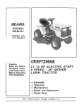
33 CHAIN SAW
OR
CHAIN SAW
MODEL NO,S.
917.353730
917.353731
|
I
IMPORTANT:
I
MODEL NOS.
917.353770
917.353771
AND INSTRUCTIONS
_
CAREFULLY
Sears,
Roebuck
and
Co_,
Chicago,
Illo 60684,
U,S.A_
MODEL
;
NUMBER_
SERIAL
NUMBEL
THE MODEL AND SERIAL NUMBERS
WILL BE FOUND ON THE MODEL
PLATE LOCATED BELOW "ON-OFF"
SWITCH
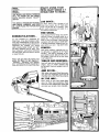
ENJOY
USING
YOUR
NEW
CRAFTSMAN
3.7
CHAIN
SAW TO MAKE...
4;
LOG
DISCS...
FIRE
WOOD...
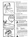
YOU SHOULD RECORD BOTH MODEL
for paths, pat os steps. Simplest of all
AND SERIAL NUMBERS AND KEEP
Chmn Saw prolects.. Cut 4 thtck slices
IN A SAFE PLACE FOR FUTURE REF-' from a log at least 10!' in diame_ter. Treat
ERENCE.
with wood preservative and place on a
fi_m bed" of crushed rock..
:
CONGRATULATIONS...
on your purchase of a Craftsman 3°7
Chain Saw. tt has been designed, engineered and manufactured to give you dependability and pe_'formanceoShould you
experience any problem you cannot
easily remedy, please contact your neareat Sears, Roebuck and Coo store_ They
have competent, welt-trained technicians
and the proper tools and parts to service
or repair this unit.
Please read and retain this manual Fol[pwlng the
]_ules for _pfe Ot2eratzon ,
"'Assqmbly", "Operation", and-Maintenance" instructions will help you achieve a
long, safe, service life for your Chain Saw°
Your National Forest Ra_qgermay permit
removal of dead or downed timber for a
_odest fee -- a clear) forest is lesssuscept!ble tO fires and disease_Quick burning
evergreens will split easily to kindle slower burning hardwoods_ Measure "_i0urfireplace before you start -- logs don_t bend.
FENCES...
make good neighbors, especially the rustic split rails so suggestive of the "good
old days". Use cedar or redwood, or any
good splitting wood. Split rails with an ax
and wedges, notch and fit so your fence
is self supporting.,
TABLES
AND
BENCHES...
from half logs, slices or planks drilled and
pegged. Legs of smaller diameter logs
are whittled, fitted and wedged into drilled tops.
With other tools, good Chain S_w technique, and your imagination you'll soon be
inventing many other Chain Saw projects.
BY
THE
1NAY...
Don't forget to visit your' nearby Sears
store for Chain Saw accessories, Chain
Guards and Saw Maintenance Items that
can make your projects more enjoyable°
TABLE
OF CONTENTS
WARRANTY
RULES
.................
FOR SAFE
ASSEMBLY
OPERATION
1
OPERATION
INSTRUCTIONS
INSTRUCTIONS
......
...........
2
...........
5
MAINTENANCE
INSTRUCTIONS
......
CHAIN SHARPENING
INSTRUCTIONS
TROUBLE
REPAIR
SHOOTING
1
............
9
., 9
16
FULL 90-DAY
WARRANTY
For 90 days from the date of purchase, Sears will repair any defect in material or workmanship
in this gasoline chain saw at no
charge
If the chain saw is used for commercial or rental purpo_s, the
warranty applies for only thirty days from the date of purchar_.
Warranty service is available
or Service Center throughout
by contacting the nearest
the United States_
This warranty
gives you specific legal rights, and
have other rights which vary from state to state.
Sears, Roebuck
Sears Tower
BSC 41-3
PARTS
.............
18
LOOK FOR THIS SYMBOl. TO POINT
OUT IMPORTANT SAFETY PRECAUTIONS. IT MEANS -- ATTENTION!
BECOME ALERT! YOUR SAFETY IS
INVOLVED,
Chicago,
!il
Sears store
you may also
and Co,1
60684
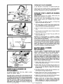
SPECIAL NOTE
In some states, such as California, laws covering chain saws (having internal combustion engines}, when used in areas covered by
forests, brush or grass (excluding residential lawns and landscaped areas}, necessitate fitting the saw's muffler with an additional
heat shield to reduce muffler surface temperatures, Sears offers such a shield as an optional accessory kit° Muffler Heat Shield Kit
Catalog No. 32-36178 can be purchased at your Sears Service Center. Check with your state conservation or forestry department
about their regulations before operating this Sears Chain Saw on any forest-covered, brush-covered or grass-covered areas, Oregon
and Washington have similar requirements with respect to forest-covered lands°
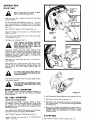
RULES FOR SAFE OPERATION
Keep hands, body and clothing away from the moving
1o KNOW YOUR ShtW,
chain°
Use your Owner s Manual to become familiar with your
Saw and proper cutting methods before you begin cutting,
Stop Saw Engine and wear heavy gloves when handling
Saw Muffler area or Chain.
2, LIMIT
YOUR SAW'S USE TO TRAINED
ADULTS.
Never allow children to operate your Saw or adults lacking
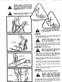
6_
LOOK OUT FOR KICKBACK, When the moving chain or
proper instruction,,
the tip of the guide bar is stubbed or pinched in a cut, the
bar and chain can be thrown up and back or down and
3, PLAN AHEAD.
back with considerable force° THIS IS KICKBACK!
Keep onlookers and pets a safe distance away when starting
Avoid touching limbs or other objects with the tip of the
or operating your Saw,,
Guide Bar while the chain is moving.
USE EYE, EAR, HEAD, HAND, AND FOOT PROTECStand slightly to the side rather than directly behind Guide
TION and never wear loose clothing or jewerly.,
Bar°
Take time to carefully study your sawing operation, planDo not reach above shoulder height or outward beyond
ning cuts required and clearing retreat paths° Be alert to
your point of positive Saw control as you cut.
conditions which might alter your plans as you are cutting,
Avoid striking cement or metal, etc. buried in the wood.
4o TAKE PRECAUTIONS AGAINST FIRE,
Obtain full chain speed before cutting or resuming pre*
Take fire fighting equipment with you when operating the
vious cut. Start cutting with fro_t of _3aw Frame against
Saw in dry areas_
log or tree. Never use your Saw for boring.0
Handle fuel with care:
Plan c_tting to avoid situations which might cause Guide
a. Use approved gasoline and oil containers and store them
Bar to be pinched in a cut. If, however, your Saw does beaway from heat or open flame, out of the reach of chilcome pinched in a cut, STOP THE ENGINE BEFORE REdren,
MOVING IT.
bo Turn the engine off and let your Saw cool before removing the fuel tank cap and refueling your Saw,
7. MAINTAIN SAW IN GOOD WORKING ORDER,
d. Do not smoke while operating or refueling your Saw.
Keep your entire Saw clean of sawdust, chaff, oil or fuel
d. Refuel your Saw outdoors in a clear area.
and keep handles clean and dry.
e, Wipe your Saw clean of any spilled oil or fuel and move
Keep oil and fuel caps, bolts and screws tight.
away from the fueling area before starting your Saw,
Make all adjustments (except carburetor) with engine stopNever run the Saw without the muffler or muffler screen.
ped and spark plug disconnected.
5. RESPECT YOUR SAW.
Adjust carburetor so that chain stops when throttle trigger
Do not start or run Saw indoors to avoid Carbon Monoxide
is released.
poisoning from exhaust gases.
Keep chain sharp and properly tensioned.
When starting Saw, pick an area clear of loose gravel or
Stop your Saw, inspect and repair if necessary after chain
flammable debris, hold Saw firmly to the ground without
strikes a foreign object.
letting the Guide Bar touch anything, and start your Saw
All service other than that included in this Manual should
without assistance,
be performed by a competent technician.
Take a position uphill of expected fall or roll of logs, then
practice cutting on fallen logs before felling trees° Take
8, TRANSPORT AND STORE SAFELY.
special care when cutting wood that is under stress.
Stop your Saw engine before setting it down or carrying it
Don_t operate your Saw when you're tired° Fight carelessto another location.
ness and avoid distractions,
Carry stopped Saw with Guide Bar behind (preferably
Cut wood only,
covered) and muffler away from your body°
When sawing, maintain a firm grip with both hands, thumbs
Cool your Saw completely and cover Guide Bar before
transporting in any vehicle,
opposing fingers and a secure footing. Do not saw on ladders, platforms or in any other position which might enDrain oil and fuel tank and run Saw engine to use remain _
danger your balance and thus cause loss of positive Saw
ing fuel, then cool completely before storing in any encontrol.
closure,
-1-
NOTE:
MODEL
917.353770
tS
ILLUSTRATED
THROUGHOUT THIS
MANUAL
WHERE
INSTRUCTIONS
APPLY
TO
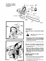
ALL MODELS,
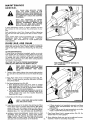
HAND
CHAIN
SAW
OIL
GUARD
GUIDE
BAR
WRENCH
FRAM_
GUIDE
/F'_
BAR
//
NUTS
GUIDE
BAR
CHAIN
GUIDES
CHAIN
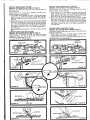
FIGURE 1
HAND
ASSEMBLY
YOU SHOULD
FRAME; FUEL
HOSES_
NUT
HEAR A RATTLE
INSIDE THE SAW
AND OiL FILTERS ARE ON FLEXIBLE
SPRING
WASHER
FLAT
WASHER
"_"
FIGURE 2
BASE
PLATE
WEAR HEAVY GLOVES
LING SAW CHAIN,
WASHER
MACHtN E
SCREW
.
WHEN
HAND-
Identif_¢ the Saw parts (Fig, 1) as ypu remove them from
the shipping carton, NOTE: THE GUIDE BAR WRENCH
(FURNISHED WITH YOUR SAW) AND A 7/16"WRENCH
ARE THE ONLY TOOLS YOU WILL NEED TO ASSEMBLE AND ADJUST YOUR SAW.
2o Soak Chain in light oil for a few minutes before assembly,
INSTALLATION
OF HAND
GUARD
1. Remove Nut, Spring Washer and Flat Washer from Stud
in Front Handle (Fig. 2L
2_
Assemble Hand Guard over Bushing and against Flat
Washer, Next, assemble remaining Flat Washer and Spring
Washer. NOTE:
CONCAVE
SURFACE
OF SPRING
WASHER MUST FACE FLAT WASHER. Secure with Nut.
Tighten Nut until Hand Guard is secure to handle, DO NOT
OVERTIGHTEN.
Hand Guard must move easily to fill
fuel and oil tanks_
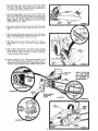
INSTALLATION
A ND C H AIN
OF
BAR
1o Using the Guide Bar Wrench, remove the two Guide Bar
Nuts and Outer Chain Guide from Guide Bar Studs (Fig_ 3L
2. Remove Machine Screw from Base Plate (Fig. 2).
-2-
3. Be sure upper and lower" edges of inner Chain Guide are
bent TOWARD the Saw Frame (Fig. 3).
'
4. Place Guide Bar over Guide Bar Studs, NOTE:BAR
GOES
ON ONLY ONE WAY--NOTE CONTOUR OF BAR (FIG.
4)° ALSO, THE SMALL ROUND HOLE COMPLETELY
THRU THE BAR IS BELOW BAR SLOT.
GUIDE
5, Hold Guide Bar slightly away from the Saw Frame., Push
_Bar as far TOWARD the Chain Sprocket as it will go. Place
Chain Drive Links around Chain Sprocket and in Guide Bar
groove (Fig. 5), SHARP EDGES OF CUTTERS MOVE
AWAY
FROM THE SAW FRAME ON TOP OF THE
GUIDE BAR (FIGo 5- INSET),
B, Place Outer Chain Guide on Guide
and lower edges bent AWAY
from
6-A) o
ROUND
HOLE
BAR
GUIDE
BAR
.FIGURE
4
Bar Studs with upper
the Saw Frame (Fig,,
CHAIN
TRAVEl
7. (Fig. 6). Push Guide Bar against Saw Frame. (Fig. 6-A)o
Hole in Guide Bar should be centered in slot of Outer Chain
Guide It may be necessary to pull Bar forward.
DRIVE'
LINKS
8o (Fig., 6-B)o Center Chain Tightener Block Pin in Slot of
Chain Shield. To do this, turn Chain Tension Adjusting
Screw,
go (Fig° 6), Place Chain Shield onto Guide Bar Studs, Holding
Chain Shield to Frame, turn Saw on its side (Fig. 6-C)_
Chain Tightener Block Pin must be in Hole of Guide Bar,
in order to tension Chain (Page 4).
CHAIN
10. Set Saw upright (Fig° 7), Assemble Chain Shield to Saw
Frame with Guide Bar Nuts_ Assemble Machine Screw in
rear corner of Chain Shiel& NOTE: Tighten Machine Screw
securely, Tighten Guide Bar Nuts FINGER TIGHT ONLY.
SPROCKETI
GUIDE
BAR
FIGURE 5
GUIDE BAR
SAW
CHAIN
GUIDE
GUIDE
GUIDE
BAR
BAR
VIEW OF SAW ON
ITS LEFT
HAND
SIDE LOOKING UP
TO BOTTOM
OF
CHAIN SHIELD.
'tGHTENEB
PIN
HOLE
FIGURE
CHAIN
SHIELD
CHAIN
TENSION
ADJ USTI N G
SCREW
FIGURE 6
GUIDE
BAR
FIGURE 6C
SHIEL[
SLOT
CHAIN
TENSION
ADJUSTING
CHAIN
TIGHTE
BLOCK
PIN
-3-
TENSION
CHAIN
Hold
end of
Guide
Bar upo Leave Guide
FINGER
TIGHT
ONLY.
Turn
Chain Tension
Screw clockwise
until
there
is no droop
or
Chain
(Fig. 8),,
2_
CHAIN TENSION
EW
LOOSEr
GUIDE
Still holding end of
securely
(Fig,, 9).
Bar up,
tighter}
Guide
Bar
Nuts
3_ Test Chain tension by lifting Chain at the center of the
Guide Bar. Bottoms of Cutters should raise approx=mately
1/8 inch above the Guide Bar (Fig, 9).
a. If Bottoms of Chain Cutters can be lifted more than 1/8
inch above Guide Bar, LOOSEN GUIDE BAR NUTS.
Turn Chain Tension Adjusting
Screw clockwise to
tighten tension, TIGHTEN
GUIDE BAR NUTS and
test again.
b, if Bottoms of Chain Cutters cannot be lifted 1/16 inch
above the Guide Bar, or if the Chain cannot be pulled
easily around the Bar by hand, LOOSEN GUIDE BAR
NUTS_ Turn Chain Tension Adjusting Screw counterclockwise to loosen tension, TIGHTEN
GUIDE BAR
NUTS and test again,
FILL
FIGURE 8
Guide
Bar Nuts
Adjusting
sag in the
CHAIN
OIL
TANK
1. Push Hand Guard to the rear for easier filling of Fuel and
Oil Tanks (Fig. 10).
2_ Fill Chain Oil Tank (Fig, 10) with Sears Bar' and Chain
Lubricant--suitable
for use in any temperature_ You may
also use any good multi-grade automotive type oil. if used
in temperatures below 0°F, thin oil with a small amount
of kerosene (approximately
6 ounces per quark of oil).
Tighten Cap securely. NOTE: THIS TANK IS FOR BAR
AND CHAIN LUBRICATION
ONLY.
MIX
FUEL
AND
FILL
FUEL
TANK
MIX SAW FUEL IN AN AREA WITH ADEQUATE
VENTILATION
AND
AWAY
FROM HEAT OR FLAME,
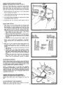
t. Mix fuel.. Prepare only enough to last for one or two days
cutting_
a. Use fresh Regular Grade Gasoline leaded or unleaded,
however, DO NOT SWITCH TO LEAD-FREE GASOLINE IF INITIAL OPERATION USED LEADED GASOLINEo Do not use Premium Grade or White Gasoline,
Mix in a ratio of 16 to 1 with Sears Chain Saw Engine
Oil or SAE 30 non-detergent oif for 2 cycle air cooled
engine fuel mixing,,
Gasoline
1 gallon
2 gallons
2 - 1/2 gallons
5 gallons
Oil
8
16
20
40
ounces (1/'2 pint)
ounces (1 pint)
ounces (1 - 1/4 pints)
ounces (1 quart + 1/2 pint)
b,, Pour half of the gasoline into a clean container_ Add all
of the oil and shake or stir vigorously, Add remainder
of the gasoline and shake or stir again_ When preparing
rue| mixture in low temperatures, thin the oil with
some of the gasoline before adding it to the gasoline.
NOTE: NEVER
MIX FUEL IN THE CHAIN SAW
FUELTANK_
2o Fill Fuel Tank (Fig_ 10). NOTE: DO NOT OVERFILL.
ALLOW 3/4 INCH FOR EXPANSION. Tighten Cap secure
ly.
CAP
KEEP THE HANDLES DRY,
OIL OR FUEL M|XTURE.
CLEAN
OF
OPERATION
STARTING
MOVE CHAIN SAW AT LEAST 10 FEET
AWAY FROM FUELING POINT.,
Make sure your Saw is fueled and Chain Oil Tank
properly (Page4).
filled
Set the Automatic Oiler Metering Knob at 1 - 1/2 turns
open (counterclockwise).
Press Manual Oiler Pump Button
several times to force oil lubrication onto Bar and Chain
(Fig. 11),
Move "ON-OFF"
Switch to "ON"
position
(Fig° tt),
Squeeze Throttle Lever and push in on Throttle
(Fig's. 11 and 12),
Detent
Push Compression Release Button down and back to latch
in this position (Fig, 12),,
Pull Choke out completely
TAKE
FIGURE 11
(Fig_, 11),
PROPER
STARTING
POSITION
BRIS-FREE
AREA)
RIGHT
FOOT
IN
WITH
REAR SAW
HANDLE
ON THE
ANDGROUND
LEFT HAND
(IN A DE_
ON
FRONT HANDLE (FIG. 13).
Pull Starter Handle slowly until a slight
(between 2 and 4 inches) then finish the
peat as necessary_ holding Starter Handle
avoiding a free
snap rewind. NOTE:
STARTER
HANDLE
MORE THAN 2
AVOID CORD DAMAGE,,
resistance is felt
pull sharply, Reas starter recoils
DO NOT PULL
- 1/2 FEET TO
When Saw fires, push Choke half way in to prevent En.*
II
g. ne llf OOolng
When engine starts, squeeze Throttle Lever fully to release
Throttle
Detent and Compression Release Button. The
Saw is now at IDLE-THE
CHAIN SHOULD NOT BE
MOVING°
IF CHAIN DOES MOVE WITH SAW AT
IDLE, THE CARBURETOR
MUST BE ADJUSTED (PAGE 12).
Push Choke in as engine warms or as engine begins to labor
from overrich mixture,
THE MUFFLER AND IMMEDIATE
BECOME HOT WHEN OPERATING
SAW ENGINE.
_/ARM
ENGINE
)//_/
STARTER
E
AREA
YOUR
STARTING
nce the engine is warm, choking is usually not necessary to
start. Choking a warm engine or over-choking a cold engine
ill cause flooding.
lOT
IAPOR
FUEL
3. Push Compression Release Button down and back (Fig, 12).
STARTING
4, Pull Choke out as far as it will go (Fig. 1 1).
LOCK CONDITIONS)
hot weather (above 90°F.) if engine is difficult to restart
ter refueling, or shortly after being shut-off, it may be the
suit of vapor lock. This condition will be minimized by
;ing gasoline for the fuel mixture that has been correctly
ended for the season°
this VAPOR LOCK CONDITION should occur the followg procedures will minimize engine restart problems,
. Move "ON-OFF"
Switch to "ON"
FIGURE 13
5. Pull Starter with shor_, r_pid movements until Engine fires,
Push Choke halfway
IN and continue starting procedure
until engine runs.
6. Hold at full Throttle and gradually push Choke f_lly in.
A SHO_,T PERIOD OF ENGINE OPERATION AT HALF
CHOKE
MAY BE REQUIRED
TO CLEAR VAPOR
FROM SYSTEM°
position (Fig, 11)_
STOPPING
Squeeze Throttle Lever and push in on Throttle
, If
(Figs., 11 and 12),
Detent
-5 - Flip _ON-OFF"
Switch to _'OFF" position
(Fig, t t),
USING
YOUR
CHAIN
OILING
SYSTEM
1, Press the Manual Oiler Pump Button
often during the first
few minutes
of operation
even if you are not cutting wood
(Fig, 14).
2+ The Automatic Oiler Metering Knob setting at 1 - 1/2 turns
open is for green wood; if seasoned hard wood is being cut,
more oil will be required -* turn Knob counterclockwise
to
increase oil flow (Fig, 14)+
3+ As you cut wood, especially if Saw and oil are cold, use the
Manual Oiler' Button to temporarily
increase the amount
of oil delivered to the chain. Check oil level as you cut by
pressing Manual Oiler Button,
Less resistance indicates
Chain Oil Tank needs refilling.
4, Keep Chain Oil Tank fulI+ YOU CAN EXPECT TO USE
ALMOST ONE TANK OF CHAIN OIL FOR EACH TANK
OF FUEL USED,
CHECK
¢
BEFORE
YOU
CUT
lS THE CHAIN TENSIONED PROPERLY? A chain
can hammer itself to pieces if too loose -- and burn
up if too tight! (See page 4),
IS THE POWER SHARP KNOB iN STORAGE POSI_
TION? Knob should be in the far right hand position
in Support Plate (Fig. 14)+
¢
ARE THE CHAIN AND BAR GETTING ENOUGH
OIL? Throttle up to cutting speed for a few seconds
holding Bar Nose approximately
six inches from test
surface+ Enough oil should be thrown from chain to
mark test surface (Fig. 15}. Open Automatic
Oiter
Metering Knob farther if necessary.
TOUCH
TEST ALLOW
SURFACE. BAR
DO
NOT
q_
USING
NOSE
TO
forming"ALL
ARE
Rroperly
SYSTEMS
.pleaseGO"?
check if our
yourhandy
Saw i_n't
Trouble
perShooting- section on pages 16 and 17+
GOOD
SAWING
TECHNIQUE
Practice cutting a few limbs or small fogs to get the "feel '_ of
your' Saw using Good Sawing Technique,
USE A FIRM GRIP (THUMBS OPPOSING
FINGERS) WITH LEFT HAND ON FRONT
HANDLE AND RIGHT HAND ON REAR
HANDLE.
KEEP A SECURE BALANCED
FOOTING TO THE LEFT OF THE SAW
AND DON'T OVERREACH (FIG. 16),
1. Squeeze Throttle Lever fully before starting the chain into wood+ The chain will cut more efficiently with engine
at top speed+
2+ Start cutting with the front of Saw Frame against the Ioc,
or tree and pivot as you cut so that the Bar Nose enters th_
cut last (Fig. t6)+
3, Allow the Chain to cut for you and hold Saw so that the
Chain runs free in the opening cut. You need not rock th_
Saw back and forth in the cut or use great force, If y0u dc
use excessive force to cut, damage to the bar+,chain, o_
engine may result+
4. Keep Saw chain at cutting speed until Bar is completel_
free of cut, ttmn release Throttle
Lever to idle engim
USING
GOOD
TREE
FELLING
TECHNIQUE
A
SAFE
WORKING
PROCEDURE
IS
YOUR
FIRST
LINE
OF DEFENSE
TOWARD
PREVENTING
ACCIDENTS
1. SIZE UP THE TREE.
a. Determine
natural felling
direction
....
-- toward the direction
of natural lean.
-- toward the side with more or heavier branches.,
-- (if heavily leaved) with the direction
of the wind.t
b., Avoid felling
a tree ....
-- if it shows signs of rot which may make felling unpredictable.
-- if it's natural
felling
direction
must be changed to
avoid obstacles.,
-- if hanging dead limbs (_widov_
makers =_) cannot
be
removed before felling.,
-- if wind is strong or gusty.
2. PLAN YOUR ESCAPE ROUTE, Choose a route back and
to one side of the direction of tree fall (Fig, 17),, You
should plan a route that will place you at least twenty feet
from the stump at the time the tree hits the ground,
3. CLEAR THE BRUSH AND DEBRIS from around the tree
and along your escape route, Examine tree in cutting area
and remove dirt or foreign material which might dull or
break the chain as you cut_
4.
BACKCUT
("FELLING
CUT"}
HINGE
UNDERCUT
("NOTCH")
FELL THE T_EE.
,
a. Undercut
( notch
) the tree on the side of natural
fall
(Fig. 18),
-- Make the first cut horizontally
I/3 the tree diameter
at a comfortable
working
height.
-- Finish the undercut
with
sloping
cut to meet but
not cross the first,,
-- Clean out the undercut
wood.
fl
,
Ii
b. Backcut
( felling
cut )the tree opposite the notch (Fig..
18).
-
Make the horizontal
felling
cut opposite
the side of
natural
fall. at least 2 inches above the horizontal
undercut,,
-- For trees larger than bar length make two felling cuts
pivoting bar nose in last, in on one side. then pivoting
in from the other to complete
the cut (Fig. 19).
-- Some trees may need to be pushed into the undercut. Drive wedges into the backcut,
stopping
often
to drive wedges tight but taking care not to place
them where they will interfere with cutting
or direction of fallo Use plastic or wood wedges so that they
cannot dull saw chain if accidentally
hit.
-- DO NOT CUT COMPLETELY
THROUGH
TO THE
UNDERCUT.
Leave at least a 2 inch hinge to hold
and guide the tree down in the direction
you planned
and keep the tree from snapping off the stump., Make
sure to keep the hinge a uniform
thickness to prevent the tree from pivoting
on the stump°
5. ESCAPE.
As your backcut
nears the undercut,
watch the
treetop
and the cut for signs of movement.,
Be alert -- as
soon as the tree starts to move, pul! your saw from the
tree, turn it off, put it down, and move away quickly
on
you[ escape route. If your saw is pinched in the backcut-don t wait until
the falling
tree frees it., Shut if off and
leave itl
BE ALERT
TO CONDITIONS
WHICH
MIGHT
ALTER
YOUR PLANNED
ESCAPE ROUTE AND WATCH WHERE YOU
ARE GOINGI
6. STUDY THE STUMP. Improve your felling technique by
analyzing your work (Fig. 20).
a. Did the undercuts meet without crossing?
b;. Was the backcut horizontal, parallel to the undercut and
at least 2 inches above it?
c,, Was the hinge at least 2 inches thick and of uniform
thickness?
-7-
IIIIIIIIIII
IIIIII
Ot RECTION
OF FALL
FIGURE
20
PREVENT KICKBACK. NEVER LET THE
MOVING
CHAIN AT THE BAR NOSE
CATCH OR STUB ITSELF OR THE BAR
WILL RECOIL BACK AND UP OR DOWN
DEPENDING
ON WHERE IT HAS BEEN
STUBBED (FIG. 21).
ALWAYS STOP THE ENGINE BEFORE
MOVING FROM TREE TO TREE.
FIGURE
21
,TOPCUT
IF YOUR SAW SHOULD BECOME PINCHED IN A CUT, STOP THE ENGINE BEFORE REMOVING IT.
FIGURE 22
LIMBING
I,, Cut branches and limbs from the felled tree starting at the
base, working towards the top, Leave the larger lower limbs
to support the tree as you work°
CUTTING
LIMBS WHICH MAY SPRING
EXTREME
CARE
SHOUL.D BE TAKEN
OUT
IN ANY
DIRECTION,
2. Large lower branches which support the felled tree's weight
should first be top cut° Then, undercut them so the cut
opens away from the saw, n that way, your saw won't be
closed on or pinched (Fig,. 22}.
BUCKING
(CUTTING
LOGS)
HIND IT AND TAKE A POSITION UPSTAND
HILL OFTO
POSSIBLE
SIDE OFLOG
THEROLL.
SAW, NOT BELogs resting on the ground for their entire length can be
bucked from the top ( overbuck ),, Stop cutting before
passing through the log; it takes only a few seconds of cutting dirt to ruin a chain. Roll log over to finish cut,,
I
II
|#
Logs that are only suppo,r,ted on one.end can be cut from
below, 1/3 log diameter ('under'buck")'
then finished '_rom
the top (Fig. 23),
2_
.
Logs that are supported on both ends can be overbucked
1/3 log diameter then finished from the bottom (FIgo 24).
4. Use wedges if necessary to prevent log from pinching saw
bar in the cut.
5. Smaller, lighter logs may need to be blocked to prevent
them from rolling off their supports.
PRUNING
(CUTTING LIMBS FROM STANDING TREES)
DO NOT
SAW ON LADDERS, PLATFORMS, IN TREES OR IN ANY OTHER
POSITION
WHICH MIGHT
ENDANGER
YOUR
BALANCE AND THUS CAUSE
LOSS OF POSITIVE
SAW CONTROL.
When removing a limb from a growing tree, make an undercut
1/4 limb diameter near the trunk and finish with a top cut a
little farther out from the trunk. After removing the limb,
fhJ_h
_l_t
fh_
_t=lh
noor
th_
tr_lnk
{_';rt
_}_
MAINTENANCE
GENERAL
ALL
CHAIN
SAW SERVICE,
OTHER
THAN
THE ITEMS LISTED
IN THE
OWNER'S MANUAL MAINTENANCE
INSTRUCTIONS, SHOULD BE PERFORMED
BY COMPETENT CHAIN SAW SERVICE
PERSONNEL_
WITH
THE
EXCEPTION
OF POWER
SHARPENING
AND CARBURETOR
AD_
JUSTING,
DISCONNECT
SPARK PLUG
WIRE AND LET SAW COOL BEFORE
MAKING ADJUSTMENTS OR REPAIR_
A good maintenance program of regular inspection
will increase the life and maintain the performance
Saw°
and care
of your
STONE
ADJUSTI
KNOB
POWER SHARP KNOB
(SHARPENING POSITION)
Each working day, check Nuts, Screws and Wires, tightening
any that are loose and replacing those that are worn or damp
aged.
NOTE: WHEN REPLACNG
FASTENERS USEATHREAD
ADHESIVE.
SUCH AS "THREAD
LOCK",--LOCTITE
SEALANT 'r, ETC. AVAILABLE
AT YOUR SEARS SERVICE CENTER.
GUIDE
BAR
AND
NG
FIGURE 26
CHAIN
Service life of your Bar and Chain will be greatly increased by
roper Saw use-correct Chain Tension (page 4), Lubrication
page 6) and regular maintenance-Sharpening,
Bar Deburring,
etco
CHAIN
SHARPENING
If wood chips are becoming increasingly smaller as you cut,
from normal wear or accidental running Chain in dirt or sand,
your Chain may need sharpening. Check Chain for sharpness
or damage after every refueling and sharpen perhaps every
third or fourth refueling; more often when cutting seasoned
hard wood or frozen wood.
CUTTER
(MODEL
TOP PLATE POWER SHARPENING
917.353770 & 917,353771 ONLY)
SHARPENING
uSTONE
_
CHAIN
VIEW FROM BOTTOM OF SAW ON ITS
LEFT HAND SIDE
MAKE SURE INSIDE
CHAIN
SHIELD
AND POWER SHARP PARTS ARE FREE
OF PACKED SAWDUST
AND
WOOD
CHIPS.
t. Tension Chain slightly tighter than normal cutting tension
but still able to be pulled easily around the Guide Bar (page
4).
2o Place Power Sharp Knob in Sharpening I_OSition (Fig. 26)°
NOTE: To make operation smoother and easier, lift Power
Sharp Knob slightly_
3o Set Stone Adjusting Knob (Fig. 26).
ao Move Sharpening Stone away from chain by turning
Stone Adjusting Knob clockwise as far in as possible.
b. Move Stone closer to chain by turning Stone Adjusting
Knob 1 click at a time counterclockwise,
c. Test proper Stone position by pulling chain around bar
with gloved hand. Leave Stone Adjusting Knob at the
setting reached when chain first touches Sharpening
Stone (Fig° 26- Inset)°
4. Start Saw and throttle up to cutting speed.
KEEP A FIRM GRIP AND AVOID
BAR AND CHAIN AREA.
GUIDE
5. Leave Saw on ground in the debris free starting area° Move
Power Sharp Knob up and back (ful! range-Figo26) rapidly
several times. This will sharpen Cutters on both sides of
Chain and maintain a flat surface on the Sharpening Stone.
SPARKS WILL FLY AS CUTTERS ARE SHARPENED.
6o NORMAL CHAIN SHARPENING TAKES ONLY A FEW
SECONDS. Stop Saw Engine to inspect Chain visually
Edg=_sof Cutter Top Plate will took clean and sharp and,
sighting down the Chain, Cutter Tops will be flat, parallel
with each other and perpendicular to the Guide Bar,
-9.
a, If Cutter abrasion is not completely removed, turn Stone
Adjusting
Knob counterclockwise
one click at a time
and resharpen,
bo If Cutter Tops are not flat and perpendicular to the Bar
rotate or replace Sharpening Stone (page 1t)o
7o Place Power Sharp Knob in storage position
tension Chain for cutting (page 4)°
(Fig. 27)° Re-
8. Stone Adjusting Knob may need to be readjusted (counterclockwise 1 click} for succeeding sharpenings.
CUTTER
(MODEL
SIDE PLATE FILING
917.353770 & 917,353771
ONL ¥_
File Cutter Side Plates (Fig. 28) after every third to fifth Top
Plate sharpening.
Tension
Chain so it is snug, won't
wobble on the bar_ Use a
chain filing vise if one is available,,
1,, Place 5/32 File and Holder on Cutter Top Plate and Depth
Gauge. Line up Guide Mark Parallel to Guide Bar (Fig. 29).
Keep File Holder firmly
level (perpendicular
to Guide Bar)
(Fig. 30).
2, Make a light pressure file stroke from inside toward outside
of Cutters,. Take care not to nick Cutters on return stroke,,
Use a few file strokes for each Cutter on one side of Chain
then move to the other side of the Guide Bar to file opposing Cutters,
Rotate the File in its Holder occasionally
to
even File wear.
Measure Side Plate projection
it should be 1/32 inch (Fig.
31).
CUTTER
(MODEL
DEPTH GAUGE FILING
917.353770 & 917.353771
Depth Gauges are lowered
as Cutter
sharpened.
Use a Flat File to round
maintaining
original shape (Fig_ 32).
Re.tension
Chain for cutting
(page 4).
ONLY)
Top
off
Plates are power
the front
corner,
CUTTER
(MODEL
TOP & SIDE PLATE FILING
917,353730 & 917,,353731 ONLY')
Tension
Chain so it is snug, won't
chain filing vise if one is available.
MARK
on the
bar, Use a
1_ Place 3/16 inch File and Holder on Cutter Top Plate and
Depth Gauge (Fig. 33),
Line up Guide Mark parallel
to
Guide Bar (Fig_ 34). Keep File Holder' Handle firmly
angled
down 10 ° from Guide Bar perpendicular
(Fig, 35}_
2. Make a light pressure file stroke from inside toward outside
of Cutters_ Take care not to nick Cutters on return stroker
Use a few file strokes for each Cutter on one side of Chain
then move to the other side of the Guide Bar to file opposing Cutters_ Rotate
the File in its Holder occasionally
to
even Fife wear,
CUTTER
(MODEL
DEPTH GAUGE FILING
917.353730 & 917,353731
ONLY)
File Cutter Depth Gauges after every third or fourth Top and
Side Plate sharpening.
1. Place Jointer
on Chain.
If Depth
Gauge projects
above
Jointer.
file it level with Flat File (Fig. 36}.
2, Round off front corner to maintain
original shape (Fig. 37).
Re-tension
Chain for' cutting
GUIDE
GUIDE
wobble
(page 4),
MARK
J
5/32
FILE & HOLDER
& HOLDER
29
FIGURE 34
FIGURE 30
FIGURE 35
FIGURE
SIDE
FIGURE 31
PLATE
1/32"
i....................
....
DEPTH
GAt
FIGURE 37
POWER
(MODEL
SHARP STONE ROTATION
917_353770
& 917o353771
ONLY)
Reverse the Power Sharp Stone to even Stone wear, perhaps
every third or fourth sharpening, as needed. An unevenly worn
Power Sharp Stone may sharpen Chain on an angle. Cutter
Tops will not look flat when sighted down the Guide Bar,
Chain will stumble through wood when cutting or cut slanted,
1. Remove
Guide
(Fig, 7)_ Remove
Bar
Nuts and Screw
in rear of Chain
2_ Loosen Stone Retaining
Screw
from Arctuating
Arm (Fig_ 38)
to slide
Power
3. Turn Stone end for end, slide it on Arctuating
tion and tighten Retaining Screw,
4, Reassemble Saw and re-tension
GUIDE
BAR
Shield
Chain Shield
Chain
Sharp
Stone
Arm, reposi-
(pages 3 and 4),
REPAIR
1. Chain Cutter and Link bottoms riding on Guide Bar Rails
will normally roll some Bar Material to the outside of the
_bails ff_pecially in actual cutting area of Guide Bar, These
urrs" should be removed as they form or they will chip
away during use taking more Bar material with them,
Check Bar for burrs at each Chain sharpening (Fig. 39),
a, Remove Guide Bar Nuts, Screw in rear of Chain Shield,
Chain Shield and Outer Chain Guide. Loosen Chain
Tension, remove Chain and Guide Bar,
bo Move your gloved hand across the flat of the Guide Bar
to feel burrs and remove them with a Flat Fife. Rounding outside Rail edges will retard further burr formation
(Fig, 40),
co Reassemble Saw and re-tension Chain (pages 3 and 4)°
NOTE: YOUR GUIDE
TYPE AND CAN ONLY
TIONo
REPLACEMENT
Normal Chain sharpening will eventually remove enough mat _
erial to weaken Cutters and cause damage during use. Individual Cutters can be replaced and sharpened to match Chain
in a Sears Service Center, however, repeated Cutter or Link
breakage indicates Chain replacement is required°
NOTE: A damaged Cutter on Top Sharp Chain (MODEL
917.353770
& 917o353771), should not be replaced by
another Cutter due to the difficulty
in sharpening it to match
other worn Cutters, Use of a Tie Strap (Fig, 28) to replace an
individual damaged Cutter will not noticeably affect the cut °
ting ability of your chain,
POWER SHARP STONE REPLACEMENT
(MODEL 917.353770 & 917.353771 ON LY)
Replace Power Sharp Stone when installing
38),
CHAIN
SPROCKET
RAIL
TOPS
POUNDED
CLOSED
AND
FILED
LEVEL,
BURRS
ROUNDED
OFF
BAR IS SPECIAL
"LO-KICK"
BE ASSEMBLED IN ONE POSI-
2o When new or newly sharpened Chain makes slanted cuts,
sometimes badly enough to prevent completion
of cuts
through large diameter logs, check for Guide Bar wear or
damage.
ao File uneven Rail top wear flat, perpendicular to Guide
Bar (Fig. 39),
b. Hammer worn, open Rails closer together to restore
correct Chain Groove--between .052 and .060 inch (Fig,
39), NOTE: MAKE SURE CHAIN RUNS EASILY IN
CORRECTED CHAIN GROOVE BEFORE REASSEMBLY.
co A badly bent Guide Bar or Rails worn low enough to
allow Chain Drive Links to ride on the Chain Groove
bottom must be professionally
serviced or reptaced:
CHAIN
RAIL
TOPS
WORN
OPEN
AND
SLANTED,
BURRS
FORMING
new Chain (Fig°
REPLACEMENT
Replace worn Chain Sprocket when installing new Chain_
Clutch Drum removal (page 14) is required,
- 11
FIGURE 39
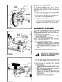
AIR
FILTER
CLEANING
An accumulation
of dirt and ,dust on your Air
Filter will
considerably
reduce your Saw s cutting
power.
Clean "t at
least once each day, more often if sawing in extremely
dusty
conditions
NOTE:
NEVER
OPERATE
SAW WITHOUT
AIR
FI LTER,
To remove Filter Cover, squeez lower 1/3 portion
and raise up as shown (Fig. 41)_
of Cover
2_ Remove and clean Air Filter with compressed
brush. Wipe Air Filter Adapter clean (Fig, 41).
air or a
3, Reposition
Air Filter as shown in Fig. 42.
Reassemble Filter Cover_
ao Insert Cover Tabs between Rear Handle Tabs (Fig. 42),
b., Squeeze lower 1/3 portion of Cover and press down into place,
4_
CARBURETOR
ADJUSTMENT
Your" Carburetor has been adjusted at the factory for the best
fuel/air mix to provide maximum Saw performance. Your
Carburetor may need resetting, however, if you notice any of
these conditions:
a, Chain moves with Saw engine idle,
bo Loss of cutting power which is not corrected
or Muffler Screen cleaning,
c, Saw engine dies or hesitates on acceleration,
NOTE:
CARELESS
ADJUSTMENTS
DAMAGE YOUR SAW ENGINE.
CAN
by Air' Filter'
SERIOUSLY
1o Make initial setting with Engine stopped:
a, Turn Idle Speed Regulating Screw out (counterclockwise); then in until Carburetor Throttle Lever just begins
to move, continue moving 2 more turns,
b, Turn Low Speed Mixture Screw in (clockwise) until
LIGHTLY
seated, then turn counterclockwise 1 - 1/8
turns.
2. Start and warm up Engine by making one or two cuts,
RETURN SAW TO DEBRIS FREE STARTING AREA FOR CARBURETOR
ADjUSTMENTS. KEEP A FIRM GRIP AND AVOID
GUIDE BAR AND CHAIN AREA.
,, .......................
, ,,, ,, ,, ,,,
,,
.
Release Throttle Lever to let Engine idle. If Engine stops,
turn Idle Speed Regulating Screw clockwise 1/8 turn at a
time as required until Engine maintains idle.
.
Adjust idle speed and Low Speed Mixture to achieve
smoothest engine idle without chain movement but allowing rapid acceleration.
a. Adjust Idle Speed Regulating Screw until Engine maintains idle speed just slower than the point at which the
chain moves.
b. Adjust Low Speed Fuel Mixture Screw for fastest idle;
then turn counterclockwise 1/4 turn.
co Squeeze Throttle Lever. If Engine falters or hesitates on
acceleration turn Low Speed Fuel Mixture Screw counterclockwise 1/16 turn at a time just enough to achieve
rapid acceleration.
d. Chain should not rotate around bar unfes_ throttle is
squeezed, If chain does move repeat Step "A o
STARTER
REPAIR
ROPE REPLACEMENT
TO "CARRY OUT THE FOLLOWING
STEPS, YOU WILL
NEED A SCREWDRIVER,
1o Remove 4 screws and remove Starter Housing (Fig, 44)
from Saw,,
2. Remove broken RoDe from Starter Handle and Starter Pulley. To replace a frayed Rope:
a_ Pull Starter Handle until several inches of Rope are exposed (Fig, 44),
b Lock Starter Pulley in place with a screwdriver.
c, Slide Starter Handle down on Rope, Untie knot in Rope
and remove Washer and Handle.
d. Hold Thumb on Starter Pulley and remove screwdriver
to SLOWLY release Spring Tension,
e. Remove Rope from Pulley,
3. Thread new Rope into hole of Starter Handle. Place Washer
on Rope and tie a secure knot in end of Rope. Position
knot and Washer inside Handle.
4, (Fig, 45). Turn Starter Pulley clockwise 9 full turns to wind
Starter Spring. Align hole in Pulley with Starter Housing
Rope Channel. Lock Pulley in place with a screwdriver.
5. Use a lighted match to melt pulley end of Rope, Pull it
thru a rag to mold an easily threaded point,,
6, Place Rope in Housing Channel and insert into Pulley hQle,
Tie a secure knot in Rope, and tap with wood block into
Rope Knot Cavity.
7. Remove screwdriver and allow Rope to slip SLOWLY
your fingers to rewind.
thru
FIGURE 45
8. Reassemble Starter Housing to Saw.
STARTER
SPRING
REPLACEMENT
TO REPLACE SPRING, YOU WILL NEED A SCREWDRIVER AND A SMALL AMOUNT OF GRAPHtTE_
t. Remove 4 screws and remove Starter Housing from
Saw.
2_ Untie Starter Rope knot at Starter Pulley (Fig, 44) and remove Rope.
3. Remove E-Ring and Washer from Starter Center Post (Fig,
46).
4. Lift out Starter Pulley and old Spring.
WEAR EYE AND HAND PROTECTION
WHEN REPLACING WORN OR BROKEN
SPRING IN CASE tT SHOULD UNCOIL
AS YOU HANDLE IT. ALLOW SPRING
TENSION
TO BE COMPLETELY
RELIEVED
AND MAKE SURE PULLEY
DISENGAGES
FROt,; SPRING BEFORE
CAREFULLY
LIFTING
PULLEY
AND
OLD SPRING FROM HOUSING.
5. Install new Spring (Fig_ 46) with loop in end of Spring over
Outer Starter Post. The Spring will wind clockwise toward
the center,
6. Apply graphite to Starter Center Post, reassemble Pulley,
Washer and E-Ring,
7, Prewind Sta_er
Replacement ,
Pulley. Refer to Step 4 of "Starter
8, Reassemble _arter
Replacement'\
PAWL
SPRING
Rope
as in steps 6, 7 and 8 of "Starter Rope
REPLACEMENT
1o Remove 4 screws and remove Starter Housing from Saw,
2o Unhook Pawl Springs and slip over Pawls°
3o Slip new Springs over Pawls and hook as shown in Fig. 47,
4, Reassemble Starter Housing to Sawn
_13
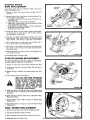
COOLING
A 3/8"
WRENCH
FIN
CLEANING
IS REQUIRED
TO REMOVE
MUFFLER..
Check air flow over the engine cylinder,,
If restricted by debris,
remove
Muffler
and clean engine and Cylinder
Cooling
Fins
(Fig° 48),, Compressed air can be used, Replace Muffler,
EXHAUST
CLEANING
PORT
& MUFFLER
Remove carbon deposits f_om cylinder,
Muffler Screen each season or as required..
SCREEN
exhaust ports
and
TO CARRY OUT THE FOLLOWING
STEPS YOU WILL
NEED: A WIRE BRUSH, 3/8" WRENCH AND A HARDWOOD STICK.
1.. Remove Muffler Cap, Baffle and Screen° Lift
Cap and remove Spark Plug (Fig. 48).
Spark Ptug
2, Pull Starter Rope to position piston below exhaust hotes,
Use a HARDWOOD STICK to scrape carbon deposits from
exhaust ports and surrounding exhaust chamber_
3. Blow out loosened carbon by pulling Starter Rope several
times.,
4. Use wire brush to clean Muffler
breaks in Screen are noted.
Screen. Replace whenever
5. Reassemble Spark Plug and Spark
Screen and Muffler Cap.
Plug Cap, Baffle
and
WARNING
TO PURCHASERS
OF INTERNAL
COMBUSTION ENGINE EQUIPMENT
MACHINERY
OR DEVICES
IN THE STATE OF CALIFORNIA.
The California law effective January 1, t974 prohibits the use
of any devices or equipment on any forest covered, brush covered, or grass covered land without providing or maintaining
in effective order, a Spark Arrestor attached to the exhaust
system. The equipment which you purchased DOES include
such a Spark Arrestor. It is a violation of law, however, to use
it unless it is maintained in effective working order.
CLUTCH
SHOE
REPLACEMENT
& SPRING
YOU WILL NEED A SPANNER WRENCH (FIG. 49) FOR
CLUTCH
REMOVAL°
ORDER
PART NUMBER 632AgA
FROM YOUR NEAREST
SEARS SERVICE CENTER,
Your Chain Saw has a centrifugal Clutch. It is designed to engage chain as engine speed increases_ Slip or disengage chain as
engine speed decreases in a heavy cutting situation or with
Throttle Lever released. If Clutch slippage is excessive so that
full engine power cannot be utilized, replace Clutch Shoes, If
Clutch does not disengage chain movement, when Throttle
Lever is released, replace Clutch Springs.
1_ Remove Chain Shield, Outer' Chain Guide, Bar and Chain
and Inner Chain Guide from Saw.
2,
SPARK
PLUG
REPLACEMENT
TO CLEAN
BRUSH OR
CLEANING
SPARK PLUG YOU
POCKET KNIFE.
OR
WILL
NEED
3.
A WIRE
Remove Spark Plug Cap and Spark Plug (Fig, 48). Tie a
knot in a nylon cord (such as a Starter Rope), Drop knotted end of rope into cylinder so engine will not go past
top dead center.
Place Spanner Wrench in Clutch and turn clockwise to unscrew Clutch from Engine Shaft (Fig_ 49).
4. Remove Clutch from Drum. Use small screwdrivers to pry
Clutch Shoes out to remove Clutch Springs (Fig. 50).
Use a wire brush or a pocket knife to clean deposits from the
5, Replace worn Clutch Shoes and Springs. We suggest Clutch
electrodes. Use care not to scratch or chip the ceramic section
Shoes and Springs be replaced at the same time,
of the Spark Plugo Be careful when removing, cleaning, gapping
and replacing the Spark Plug. If it is damaged it will not work
6. Appty a THIN coat of lithium grease to Clutch Drum
properly and must be replace_lo The proper gap between the
Needle Bearing (Fig. 5t). NOTE: AVOID USING TOO
Spark Pllug electrodes is o025'\ Should it be necessary to reMUCH GREASE
ON NEEDLE
BEARING;
GREASY
pla¢-_ the plug, use Champion CJ-6. Replace the Spark Plug
CLUTCH SHOES Wl LL CAUSE CLUTCH SLIPPAGE_
each season or when suspected of being faulty, Reattach the
_nark Phln CaD to Spark Pluq.
Reassemble Saw.
.14.7.
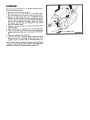
STORAGE
Never store your Chain Saw for o_er 30 days without
ing the following procedures:
perform-
_,, Drain o{1 and fuel tanks in a safe area.,
2o Start Saw and run at idle speed until the engine stops,
This will remove most of the fuel from the fuel system.
3. Remove the Spark Plug and pour a teaspoonful of oil
through the spark plug hole into the combustion chamber
(Fig,, 52)° Pull the starter rope slowly several times to distribute the oil throughout the engine. Replace the Spark
Plug tightly and pull rope until resistance is felt, closing
intake and exhaust ports°
4., Remove and clean the Bar and Chain (use gloves when
handling chain).
5, Store the Chain in a container with oil covering chain,
6. Apply a heavy film of oil over the entire Bar including the
groove for the chaim Wrap bar in heavy paper, cloth or plas_
tic.
7, Clean the outside surfaces of the saw,
8,, Cover the saw with a protective cloth or plastic and store
the saw and bar in a dry place. Always store away from
possible source of ignition such as furnaces heaters, etc_
Sears, Roebuck and Co. reserves the right to make any changes
in design or improvements without imposing any obligation to
install the same upon its items heretofore manufactured°
TROUBLE
SHOOTING
POSSIBLE REMEDY
POSSIBLE CAUSE AND CHECK
I1"1
_._._____ '%'1
I'I'1'1_"1'11#!
.....
STARTER ROPE WILL NOT REWIND
Broken Starter Spring/Not enough Pre!oad (9 turns)
Replace, page 13
STARTER DOES NOT ENGAGE FLYWHEEl+
Broken Paw{ Spring
Broken Pawls or Pins
Replace, page 13
Replace
IJZL
i'l'_''I
I','!
'i ' ,l'
,--
' ...............................
I "l
is severely
vapor
Fill Fuel Tank, page 4
Follow Starting Procedure, page 5
Repair or replace Detent
Contact your nearest Sears Service Center°
Wrap
locked
CARBURETOR FLOODS
Carburetor misadjusted
Damaged Carburetor Diaphragm
Leaking Gasket
Leaking Inlet Needle Seat
_ .........
_
:
....
:::_..::::-_-
_
................
mm,,,,,'l,
i
-_=
Procedure, page 12
......_:_
::
I
%1i+,
--
Follow Carburetor Adjusting Procedure, page 12
Clean Air' Filter or replace, page 12
Clean Spark Plug and regap or replace, page 14
Clean Exhaust Port and Muffler Screen, page 14
Tighten cover or replace Diaphragm
Contact your....rl.ea.restSears Service.Center
tHtmmHm'm,mm'mHtl
ENGINE LACKS POWER OR DIES IN THE CUT
Dirty Air Filter
Carbon build-up
Low compression. CHECK: Compression pressure tests
below 80PSt or lessened engine resistance to pulling
starter rope
/1/11
tape or replace
Follow Carburetor Adjusting Procedure, page 12
Replace Diaphragm
Contact your nearest Sears Service Center
Replace seals
Contact your nearest Sears Service Center
Contact your nearest Sears Service Center
ENGINE WILL NOT ACCELERATE
Carburetor misadjusted
Dirty Air Filter
Spark Plug fouled or Solid State weak
Carbon build-up
Carburetor Diaphragm Cover loose or Diaphragm Gasket
leaking
Broken Reed Valve
i m'm, re, ill
electrical
Follow Carburetor' Adjusting
Replace
Replace
Replace
ENGINE WILL NOT IDLE
Car buretor misadjusted
Carburetcr Diaphragm leaking
Carburetor Inlet Seat Gasket leaking
Crankshaft seals leaking
Cylinder scored or compression low
Reeds leaking or broken
H HilIHHmm rollmHmmmmHH'l
H i
Wire with
Follow Carburetor' Adjusting Procedure, page 12
Follow Starting Procedure, page 5 WITHOUT USING CHOKE
Follow Starting Instructions, page 5, then after starting WITH
CHOKE OUT RUN SAW AT FULL THROTTLE FOR A
FEW SECONDS BEFORE PUSHING CHOKE IN AND
ALLOWING SAW TO IDLE
ALLOW SAW TO COOL COMPLETELY, then follow Starting
instructions, page 5
Contact your nearest Sears Service Center'
Broken Reed Valve
..................
,,,!,,,,
,,
ENGINE DIFFICULT
OR WILL NOT START
Fuel Tank empty
Compression Release Button not in Starting Position
Throttle Detent not holding Throttle open° CHECK:
Carburetor linkage with Detent in Starting Position,
Carburetor Throttle should be 1/4 to 1/2 open
Solid State weak° CHECK: Remove Spark Plug, reattach
Plug Wire, hold Plug against engine and pull starter
rope (a strong white spark should jump across plug
points - weak Solid State produces a short red spark)
Solid State grounded,. CHECK: Wire from Solid State to
"ON-OFF" Switch for bare spots+
Carburetor misadjusted
Engine flooded.
Engine is mildly vapor locked, operating in hot weather
Engine
.................................
Clean Air Filter or replace, page 12
Clean Exhaust Port and Muffler Screen, page 14
Contact your nearest Sears Ser'_ice Department
.......................
ENGINE KNOCKS
Worn Connecting Rod or Bearings, CHECK: Remove
Starter, rotate Flywheel quickly back and forth. (Slight
play is normal, however, worn Rod or Bearings allow
considerable play and audible click)
Contact your nearest Sears Service Department
-16+
.....
::::
TROUBLE
SHOOTING
CONTINUED
POSSIBLE CAUSE AND CHECK
......
_ _
_=_:---_-_
:;_
POSSIBLE REMEDY
_;z_:
.... -....
"
----':--_-_
ENGINE BACKFIRES OR MISFIRES
Fuel Mix improper or contaminated
Spark Plug fouled
Solid State intermittently shorting. CHECK: loose or bare
wires or loose assemblies
Defective Pyramid Reed Assembly
_ --__
....
Replace
Follow Carburetor Adjustment instructions,
Replace Clutch Springs, page 14
Lubricate or replace
.........
I II!!111"[!_ _
CHAIN WILL NOT TURN WHEN THROTTLE
Chain tensioned too tight
Guide Bar Rails pinched
Clutch slipping
Carburetor misadjusted
Spr0cket Nose Bearing seized
I
l'llr
"
I'I'
.....
.,
iii ..........
;i';......
CHAIN CUTS UNSATISFACTORI
LY OR PULLS QUICKLY
Cutters dull, improperly sharpened, Depth Gaugestoo high
Chain tension too tight or loose
Chain contact with dirt, sand, or frozen wood
..........................................
- ......
-
'1
_
_
"'
....-
_
iiiiiii,,iiiii
i
ii
' '-iiiii
i]
i iiiP
1,1, _!:
_
....................
.....
:- _-
'll'l" II......
;k
pages 9 - 1t
page 4
..........
_.....................
page 4
pages 9 - 11
Contact your nearest Sears Center for Cutter replacement
or stone
.............
;i"i ii
Follow Chain Tensioning Instructions,
Follow Chain Sharpening Instructions,
Replace, page 11
Replace Chain
.
...................
' ................
I!llFII
Hold and guide Saw properly, page 6
Repair or replace, page 11
Follow Chain Sharpening and PowertShar_ Maintenance,
pages 9 - 11
m
....
CHAIN BREAKAGE
Maintain proper Chain tension
Guide Bar Rails pinched
Cutting frozen wood
Follow Chain Tensioning Instructions,
Repair Guide Bar or replace, page 11
Keep Chain very sharp, pages 9 - 11
,i
CHAIN JUMPS OFF
Chain tension too loose
Worn Guide Bar
Broken Chain Side Link
Worn Chain Sprocket
page 4
H,IH',,
..........I
Follow Chain Tensioning Instructions, page 4
Replace
Contact your nearest Sears Service Center for Chain repair
Replace, page 11
'11I'111111111
IIi
II
'!!! Iq" "1_/_ :
GUIDE BAR CHIPPED ON EDGES
Applying excessive pressure to cut
Improper Guide Bar Maintenance
Improper Chain Lubrication,, CHECK: page 6
II
MANUAL
ii ii ..................
_,: ....
I''
...........
°_
ii
!!i'l'
......
CUT TENDS TO SLANT
Improper use
Bent, wor_ or burred Guide Bar
Improper Chain sharpening, depth gauge lowering
rotation (917.353770 & 917.353771 ON LY)
I1"1"1
iiii
Follow Chain Sharpening Instructions,
Follow Chain Tensio=ning Instructions,
Resharpen chain, pages 9 - 11
CHAIN OPERATES ROUGHLY, CHATTERS OR GRABS
Chain tension too loose
Cutters not properly sharpened
Worn Chain Sprocket
Chain rivet bearing wear due to use in dirt or sand or inad_
equate chain oiling
Several cutters damaged through striking buried foreign
material
W'I'I
._.&m_
File Chain correctly or rotate or replace sharpening stone
(9t7.353770 & 9t7.353771 ONLY) pages 9- 11
Repair Guide Bar or replace, page 11
Replace Clutch Shoes, page 14
Guide Bar burred or bent or rails uneven
Clutch slipping excessively
i i .....
m
page t2
LEVER IS sQUEEZED
Follow Chain Tensioning Instructions, page 4
Repair Guide Bar or replace, page 11
Replace Clutch Shoes, page 14
Follow Carburetor Adjustment Instructions, page 12
Replace Guide Bar
CHAIN STOPS WITHIN A CUT
Chain cutter tops not filed flat
_-
"_==-_-'_='_
Drain tank and refill with freshly mixed fuel, page 4
Clean Spark Plug and regap or replace, page 14
Tighten
assemblies, wrap wires
CHAIN TURNS WHEN ENGINE IS IDLING
Carburetor misadjusted
Clutch Springs broken or weak
Clutch Bearing seized or dry
J 'I
:_===_
'
'!! II
................
Keep chain sharp, pages 9 - 1 1
Remove burrs as they form, page 11
Keep oil tank full, oil lines open and Manual Oiler operational,
page 4
II IIII
II IIIIII
III III
III
I II1"
OIL PUMP DOES NOT PUMP OIL
Clogged Oil Pump
Clogged Oil Line
Clogged Oil Filter
Replace
Blow out with compressed air
Replace
- 17 -
,,1 ,i0
..............................
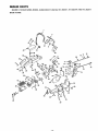
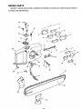
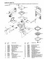
REPAIR
PARTS
SEARS 3.7 CttAIN
MAIN
SAWS-_MODEL
NUMBERS
917.353730,
917.353731,
917o353770
AND 917.353771
FRAME
43
22
44
5
27
10 11
64 47
13_
49
60
18
56
40
63
¢"
37
,_,
23
21
12
\.
SEARS
PARTS
3.7 CHAIN
MAIN
FRAME
KEY
NO.
PART
NO._
1
2
3
4
5
6
9957R
771J
t608P
772J
14_2J_
_
7
8
9
10
11
12
13
14
15
STD541410
4735R
9972R
9283H
STD551012
9057H
6167H
9991R
676A5
16
643A55
17
18
9078H
525_FL__
19
_
20
3317P
STD522508
S_1125
_
g052H
876J
676A20
9567R
643A54
9099H
6J "
32
31
33
34
_
NUMBERS
917.353730,
DESCRIPTION
KEY
NO,.
917.353731,
PART
NO.
Front Handle
Hand Guard
Washer 3/8 x 7/8 x 14 Ga. Black Oxide
Bushing
Stud
Machine Screw, Pan Hd. Phillips
Noo 10 - 24 x 3/4 Gr., 5
*Hex Nut No. 10
Hose
"
Cap
"O" Ring
*Washer 1/4x9/16x
16Ga.
Fuel Filter
"0" Ring
Oil Filter
Oil Tank Assembly (Inc. Key No_s..
t4, t7 and 18)
Fuel Tank Assembly (Inc. Key No's_
10, 12, t7 and 58)
Check Valve
Hose
37
52
12J
829J
9094H
Base Plate Assembly (Inc. Key Nots.
23 and 24}
Machine Screw, Pan Flex Hd. Slotted
1/4 - 20 x 3/4 Gr. 5
"Bolt, Hex Hd. 1/4 - 20 x 7/8 Gr_ 5
*Lockwasher 1/4
Bolt, Hex Hd, 1/4 - 20 x 2 - 5/8 Gr_ 5
E Ring
Pin
Rear Mount Assembly
Rubber Mount
Top Cover Assembly
Grommet"
Choke Control
53
54
55
56
9999R
8J
1J
676A3
57
5532P
58
59
60
61
5255R
t 6J
62
63
1392J
4J
65
64
66
------
8_
II
tl
.
917.353770
38
39
40
41
42
43
44
832J
2022J
99t7R
9918R
9919R
564P
3315P
45
46
47
584P
773J
5564P
48
49
50
51
2J
6806R
5J
AND
917.353771
DESCRIPTION
Machine Screw, Pan Hdo Phillips
No,.10-24x3Gro5
Compression Release Button
Spring
Air Filter Adapter
Air Filter
Air Filter Cover
High Crown Acorn Nut 1/4 - 20
Screw, Phillips Oval Hd. Machine
No. t0-24x
1-1/8Gr.
5
Hex Locknut 1/4- 20
Spring Washer
Screw, Pan Hal. Phillips Nor t0- 24 x
1/2 Type T
Hold Down Clip
Rubber Mount
Throttle Link
Carburetor
, (917.353730 and 917.353770 ONLY)
(917.353731 and 917.353771 ONLY)
Gasket
Throttle Detent Pin
Idle Adjustment Screw
Spring
Carburetor Adapter and Oil Pump
Assembly
Screw, Pan Hdo Slotted No, 6 - 32 x
5/16 Type 23
Hose
Baffle Plate-Air Flow
Heat Barrier
Screw, FiL Hd. Cross Recess
No. 8- 18 x t Type BT
Cotter External Hair Pin
Oil Pump Ro_
"Q
Pin
"E" Ring
507 *Bolt, Hex Hd_ !/4- 20 x 3/4 Gro 5
Warranty Label
Instruction Decal
Owners Manual
"I
21
22
23
24
25
26
27
28
29
30
SAWS--MODEL
35
36
676A21
765J
9889R
Oil
RollPump
Pin Lever
Throttle Lever
Rear Handle Assembly (Inc. Key No's_
29, 33, 35, 38 and 39)
Pin
Rear Handle Grip
9557R
77_J
*STANDARD
-19-
',
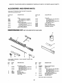
REPAIR
HARDWARE--PURCHASE
LOCALLY
REPAIR
PARTS
SEARS 3.7 CHAIN
CUTTING
SAWS--MODEL
NUMBERS 917.353730,
917.353731,
917o353770
AND 917.35377.1
AND SHARPENING
8
12
29
\
36
16
15
25
22
17
18
20
-2!1 -
REPAIR
SEARS
CUTTING
KEY
NO,
PARTS
3.7 CHAIN
AND
12
PART
NO,
4058R
9091H
23935
13
14
15
16
17
1154J
1155J
t =8
NUMBERS
917.353730,
917.353731,
917o353770
AND
917,353771
SHARPENING
24065
2
3
4
5
6
7
8
9
10
11
SAWS_-rvIODEL
19
20
2t
774J
9J
10J
632At46
22
STD502502
23
8526H1
DESCRIPT!ON
Chain Repair Kit (917 353730 and
917,35373! ONLY} contains:
Plain Tie Strap (Two)
Guard Drive Link (One)
Cutter- RoHo(One)
Cutter- L_H, (One)
Drive Link (One)
Preset Tie Strap (Two)
Huglock Nut
Chain Tightener Block
Guide Bar Nut (Flange Nut 5/16- 24 UNF)
Chain Tension Adjusting Screw
(Machine Screw, Pan Hd_ Phillips
No, 10 - 24 x 3 Gr, 5 Full Thdo)
Chain Repair Kit (917,353770 and
917.353771 ON LY) contains:
Plain Tie Strap (Two)
Guard Drive Link (One}
Preset Tie Strap (Two)
Drive Link (One)
Chain
(9t7.353730 and 917o353731 ONLY)
Sears Catalog No, 3633
+(917_353770 and 917,353771 ONLY)
Sears Catalog No, 3636
Guide Bar- 18 Sears Catalog No,
Chain Guide - Outer
Chain Guide - Inner
Stone Assembly (917.353770
& 9t7o353771 ONLY)
*Set Screw, Allen Hd_ Cup Point
I/4 - 20 x 1/4 (917.353770 &
917.353771 ONLY)
Spring (917_353770 & 917_353771
ONLY)
KEY
NO.
PART
NO
24
690J
25
26
27
28
29
30
31
32
33
34
I|
35
36
DESCRIPTION
Detent Pin (917_353770 &
917_353771 ONLY)
Detent Pin
Arctuate Arm (g 17o353770 and
692J
917.353771 ON LY)
Set Screw, Allen Hd, Cup Point
No. 6 - 32 x 1/4
3243P
Stone Retaining Screw (Machine
Screw, Truss Hd. Slotted with Nylok
No, 8 - 32 x 7/16)
Machine Screw, Pan Hd, Phillips
Noo 10 - 24 x 3/4 Gr, 5
Chain Shield
9871 R
(917°353730 and 917.353731 ON LY)
643A53
(917_353770 and 917.353771 ONLY}
687J
Foam Filler (9t7.353770
and
917°353771 ON LY)
689J
Spring Clip (917.353770 and
g17,353771 ON LY)
688J
Support Plate (917.353770 and
917_353771 ONLY)
Machine Screw, Pan Hd. Slotted Sems No, 8 -32 x 3/8 (917o353770
= and 917.353771 ONLY)
676A17
Sharpener Knob Assembly (917353770
and 917.353771 ONLY}
1008J
Adjustment Screw (g17,353770 and
9t7.353771 ONLY}
1085J
Decal - 3.7/18"
+A new Stone Assembly (Key No. 21) is shipped with
each chain
*STANDARD
HARDWARE--PURCHASE
LOCALLY
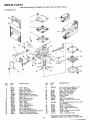
REPAIR
PARTS
SEARS 3.7 SAWS--MODEL
ENGINE,
CLUTCH
NUMBERS
917,353730,
917.353731,
AND MUFFLER
917.353770
AND 917,353771
----
Y
5
_L_,
__._
52
42
35
\
14
\
13
16
31
15
17
26
D
A
23
B
C
D
E
22
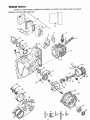
REPAIR
SEARS
ENGINE,
PARTS
3.7 SAWS--MODEL
CLUTCH
AND
NUMBERS
917.353730,
917.353731,917.353770
AND
917_353771
MUFFLER
KEY
NOo
PART
NO.
DESCRIPTION
KEY
NOo
PART
NO.
DESCRIPTION
--
643A56
26
27
632A133
642A35
I
2
3
4
5
6
7
8
9
10
11
12
13
14
15
16
676A8
676A16
6317 R
9992 R
676A27
643A5
9095H
9409H
1844 R
831J
9579R
643A12
9063H
643A18
2593R
643A1
28
29
30
31
32
33
34
35
36
37
9089H
9137H
91 t0H
9081H
9062H
9065H
9963R
643A49
9213H
643A50
38
39
40
41
42
9962R
9974R
643A43
!7
9084H
18
19
20
9973R
79J
643A48
43
44
45
46
9997 R
9998R
4058R
3178P
21
22
23
8999H
8998H
632A137
47
48
49
50
STD551125
STD541125
1136R
3250P
8473H 1
632A183
51
52
9086H1
24
25
Short Block Assembly - Complete
Engine Not Furnished (inc. Key No's.
11, 12, t4, 16 thru 20, 31,32, 33, 35,
37 thru 42, 47, 48, 50 and 51)
Muffler Cap Assembly
Baffle and Screen Assembly
Muffler Support
Muffler Base
Muffler Parts (Inc. Key No'so 1, 2 & 4)
Reed Plate Assembly
Cork Gasket
Spark Plug
Washer
Decompression Valve
Cylinder
Piston and Pin (Inc. Key No. 13)
Retaining Ring
Piston Rings (Set of 2)
Needle Bearing * Connecting Rod
Connecting Rod Assembly (lnc_ Key
No'so 15 and C)
Strip of Connecting Rod Needles
(Set of 31)
Crankshaft
Gasket
Bearing Carrier Assembly (Inc. Key NoSs..
21 and 22)
Keystone Bearing
Oil Seal
Centrifugal Clutch (tnc. Key No*s. 24,
25 and 26)
Clutch Spring
Clutch Shoes (Set of 4)
Clutch Hub and Washer Assembly
Clutch Drum and Bearing (Inc. Key No.
28)
Needle Bearing
Rimmed Sprocket
Clutch Spacer
Retainer Washer
Ball Bearing
Round Section - Retainer Ring
Gasket
Crankcase Assembly (Inc, Key No. 22)
"O _' Ring
Metering Stem Assembly (Inc. Key No.
36)
Diaphragm Gasket
Diaphragm Spring
Diaphragm Assembly
Oil Pump Cover
Machine Screw, Filo Hd. Cro Recess
Noo 8- 32 x 1/2 Gr. 5
Bushing
Muffler Stud
Huglock Nut
Machine Screw, Slotted Pan Flex Hd.
1/4- 20 x 5/8 Gr. 5
*Lockwasher 1/4
*Hex Nut 1/4 - 28 UNF
Cap Screw Socket Hd. - Special
Machine Screw, Slotted Flat Hdo
t/4- 20 x 11/16 Gr. 8
Machine Screw, Slotted Hd° - Special
Muffler Cap Assembly (See Note
Below)
*STANDARD
HARDWARE-PURCHASE
LOCALLY
NOTE: A SPECIAL MUFFLER CAP ASSEMBLY MAY BE REQUIRED BY LOCAL LAW FOR USE IN FORESTS OR BRUSH
AREAS. CHECK WITH YOUR STATE CONSERVATION
OR FORESTRY DEPARTMENT,
23 -
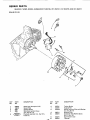
REPAIR
SEARS
SOLID
PARTS
3.7 SAWS--MODEL
NUMBERS
917,353730,
917.353731,917+353770
AND
917,353771
STATE
2
3
11
)
70
12
KEY
NO.
PART
NO.
DESCRi PTION
1
2
3
4
9409H
7682R
833J
808J
Spark Plug (Champion CJ-6)
Switch Plate
Ignition Switch
Solid State ignition Group
(Inc. Key No+ 11)
Flywheel P,_embly (inc, Key No_s.
8 and 12)
KEY
NO.
6
7
8
PART
NO+
DESCRIPTION
9072H
9070H
¢o43A14
Torsion Spring
Huglock Nut
Starter' Pawls and Posts with Springs
(Inc. Key No. 6)
Woodruff Key
Slotted Fil+ Hd. Machine Screw
No+ 8- 32 x 3/4
High Tension Lead
Flywheel
9
10
9087H
8989H
11
12
9262H
9404H
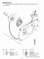
REPAIR
PARTS
SEARS
3.7 SAWS-MODEL
NUMBERS
917.353730,
917o353731,
917.353770
AND
917_35377
t
R ECOI L STARTER
6
A
KEY
NO.
1
2
3
4
5
PART
NO,
9052H
STD551012
1219J
91 t7H
9143H
DESCRIPTION
KEY
NO,
E-Ring
*Washer t/4 x 9/16 x 16 Gao
Pulley, Starter
Spring, Starter
Rope, Starter (.156 Diameter x
42" Long)
6
7
S
PART
NO.
9826R
9862_J_L
_
9
*STANDARD
- 25
DESCRIPTION
Handie, Starter
Starter Housing
Starter Assembly (Inco Key No'so
1 thru 7)
Machine Screw, Pan Hd, Phillips
No. 10 _24 x 3/4 Gr,, 5
HARDWARE-_PURCHASE
LOCALLY
REPAIR
PARTS
SEARS
3.7 CHAIN
SAWS-MODEL
NUMBERS
917.353730
AND
917,353770
ONLY
31
KEY
NO,
PART
NO.
1
2
3
4
5
6
7
8
9
10
014125
012809
004784
008805
017994
013263
013215
013278
013216
008942
11
12
13
14
t5
9094H
013652
013218
013167
011441
16
013621
DESCRIPTION
*Body Channel Reducer
*Body Channel Welch Plug (Large)
Choke Friction Ball
Choke Friction Spring
Choke Shaft & Lever'
Choke Shutter
fDiaphragm Gasket
+Diaphragm
Diaphragm Cover
Diaphragm Cover Screw & Lockwasher
(4)
tGasket
+Fuel Pump Diaphragm
1"Fuel Pump Gasket
Fuel Pump Cover
Fuel Pump Cover Ret,. Screw &
Lockwasher (4)
Idle Mixture Screw
- 26 -
KEY
NO.
PART
NOr
17
18
19
20
21
22
23
24
25
26
27
28
29
30
31
32
33
008793
013395
013210
013269
013396
012727
011503
016806
017995
013219
010280
013518
004119
010280
GS-1HS
RK-3HS
DG-1HS
*Idle Mixture Screw Spring
*Inlet Control Lever
*inlet Fulcrum Pin
*Inlet Fulcrum Pin Ret. Screw
Inlet Needle
*Inlet Screen
*Inlet Tension Spring
Main Nozzle and Jet (,028)
Throttle Shaft & Lever
Throttle Shaft Clip
*Throttle Shaft Clip Ret. Screw
*Throttle Shaft Return Spring
Throttle Shutter
*Throttle Shutter Screw & Lockwasher
+Gasket Set (inc, Parl:sMarked t )
Repair Parts Kit (tnc, Parts Marked *)
*Diaphragm & Gasket Set (Inc. Parts
Marked +)
REPAIR
PARTS
CHAIN
SAW--MODEL
NUMBER
9t7,35373t
& 917.353771
ONLY
CARBURETOR
29
I 4
KEY
NO,
PART
NO,
DESCRIPTION
KEY
NO_
PART
NOo
1
2
3
4
5
6
7
8
9
10
tl
12
13
14
15
16
17
t8
19
20
96-517
21-88
92_93
95-21
140-33
5-1656 !_40-631 _:
88-14
98-162
89-13
96-526
6242 _';
82-26
98-182,,
166-35
144-60
96-156
300-944
92-94
95-515
Screw - Cover
Cover - Fuel Pump
Gasket - Fuel Pump
Diaphragm - Fuel Pump
Screen - Fuel Inlet
Body Assembly - Carburetor
Choke - Shaft & Lever Assembly
Plug - Cup
Spring, Choke Friction
Ball - Choke Friction
Screw _Valve
Valve ,-Choke
Valve - Inlet Needle
Spring - Metering Lever
Lever - Metering
Pi n - Metering Lever
Screw -Metering Lever Pin
*Kit- Check Valve Repair (Main Nozzle)
Gasket ,, Metering Diaphragm
Diaphragm - Assembly Metering
2t
325_500
22
23
24
25
26
27
28
29
30
3I
32
33
34
35
36
37
- 27-
DESCRIPTION
Kit - Kwik (Inco Key No's. 5, 9- 11,
13 - 17, 24 -26, 30 - 32 & 34)
21-112
Cover - Metering Diaphragm
Screw - Fuel Pump Cover
96-543
9544
Diaphragm - Acc_ Pump
88-23
Plug, Welch, Idle, 3/8
98-160
Spring - Needle
112_165
Jet, Main
96-265
Screw - Idle Adjustment
Gasket - Service Set (Inc, Key No_s.
92-524
3& 19)
Kit - Gasket/Diaphragm (tnc, Key No=s,
350-500
3,4, 19& 20)
98-26t
Spring - Acc, Pump
98-163
Spring • Throttle Return
16-33
Ring - Throttle Shaft Retainer
Needle _ Idle
102-56:,
_._,: Throttle - Shaft & Lever Assembly
30-808
3444 _-,,_ Valve - Throttle
Cover - Accelerator Pump
21-116
*INCLUDES VALVE DISC CHECK AND SEAT
ASSEMBLY CHECK VALVE (NOT ILLUSTRATED)
SEARS 3.7 CHAIN
SAWS--MODEL
ACCESSORIES
AND
REPAIR
AVAI LABLE THROUGH YOUR NEAREST
VICE OR CATALOG OUTLET+
CATALOG
NO+
NUMBERS
917.353730,
36516
36178
MAINTENANCE
KIT
AND 917.353771
SEARS SER+
CATALOG
NO,
Chain
(917,353730 & 917+353731)
(917.353770 & 917+353771 )
Guide Bar 18"
Chain File and Guide
3/16" Diameter' (917.353730 &
917.353731 ON LY)
5/32" Diameter (917+353770 &
917.353771 ONLY)
Muffler Heat Shield Kit
36501
917,353770
PARTS
D ESCR _PTION
3633
3636
36367
917.353731,
(NOT INCLUDED
DESC R IPTION
Chain File
3/16" Diameter (917+353730 &
917.353731 ON LY)
5/32" Diameter (917.353770 &
917+353771 ONLY)
Chain Saw Case
Snap - On Chain Guard
Craftsman Chain Saw Oil
Chain/Bar Lubricant
36525
36524
36609
36512
36555
36554
WITH CHAIN
SAW)
4
11
10
AVAILABLE
THROUGH
VICE CENTER+
KEY
NO.
PART
NO.
2155R
2160R
2
4
6
780J
4001R
1338R
YOUR
NEAREST
8
SEARS SER-
DESCRIPTION
File Holder and File
3/16" Diameter (917.353730
917.353731 ON LY)
5/32" Diameter (917.353770
917+353771 ON LY)
+Wrench
+Oil, Chain Saw
Gap Gauge +025 (For
Spark Plug)
&
KEY
NO+
PART
NO.
DESCRIPTION
7
8
9
632A9A
6299H
Wrench, Clutch Spanner
Handle, File
File
3/16" Diameter (917.353730 &
917.353731 ONLY)
5/32" Diameter (917+353770 &
917,353771 ON LY)
Depth Gauge (917.353730 &
917,353731 ON LY)
Flywheel Driver
&
36548
4302R
10
5674H
tl
648A34
+IN¢.I
+28 -
t|PtFr}
WITH
CHAIN
RAW
SERVICE
N OTES
- 29 *
Printed in UoS.A.
[-S-ea rs
MODEL NOS.
917+353730
917,353731
917.353770
flBWT6BBBE8
MODEL
NUMBER
The Model Number will be found on the Model Plate located
below "ON-OF F" Switch. Always mention the Model Number'
when requesting service or repair +parts for your Chain Saw.
REPAIR
PARTS
All parts listed herein may be ordered from any SEARS, ROEBUCK AN D CO. retail or catalog store.
WHEN ORDERING
REPAIR
FOLLQWING
INFORMATION:
PARTS,
ALWAYS
GIVE
THE
® 'THE PART NUMBER
® THE PART DESCRIPTION
• THE MODEL NUMBER
® THE I_AME OF MERCHANDISE
If the parts you need are not stocked [ocafly, your' order will
be electronically
transmi1_ted to a Sears Repair Parts Distribution Center for' "expedited handling".
SEARS
SERVICE
Yogr Sears merchandise takes on added value when you discover that Sears has over 2,000 Service Units throughout the
country+ Each is staffed by Sears-trained, professional technicians using Sears approved parts and methods.
iI
i|
,.m,
Sears,
Roebuok
and
Co.,
Chicago,
..........
Ill.
60684,
U.S.A.
.rl _'J
--