1
___A_/h_
"HYDRO-GLASS"®
SELF-PRIMING
CENTRIFUGAL PUMP
Save This Manual
Future Referencel
* Installation
o Operation
® Repair Parts
Sears, Roebuck and Co., Chicago, III. 60684 U.S.A.
PRINTED
IN
U
S A
F642-7985
Carefully r_r_._._.,
manual _ _'_"
safety instructions in this
CONTENTS
Safety/Introduction
_,._ This ig tl-" _
.... ,=bol. When you see this
symbol,my-\
-_---.;,=smanual, look for one of
the follf_w H'..,"
_z_ ..... _dbe alert to the potential
for permm,'_ :_'-:-
............................
2
Warranty .....................................
3
Installation ..................................
4-6
Operation .....................................
7
Maintenance .................................
10
_
=",-_K.._...... _sabout hazards that will
cause s_ t,_,_ -_=--_
........ y, death or major property
damag_ If ,_'\'_=-_
Troubleshooting/Pump
11
[jI, WARNIN_, t_:_r_=_r.,_rns about hazards that
can calms' ._>°-_-;..... ._I injury, death or major
properly ,t_'_- _ ....
INTRODUCTION
III, CAU1 I*'_N _.._.L---_,_.,
_,.ns about hazards that will
or can cnl _' '_--- :--_-_. ,n jury or property damage
if ignore,
I
The word NOTL_ ;_'_>._ _pecial instructions which
are imp(_ I_
u_,-_-; =c _
to hazards.
_._.,
Wire motor for correct
,I_
voltage.
See "Electrical"
and motornameplate.
d_
Groundmotorbefore
,_-_ connectingto power
sectionof
supply. this manual
_lk
Hazardou_
wfll_O eCan shock, lit.n, or
cause dealh
Follow wiring instructions
in this manual when
. ,_
iI
connecting
_j
worksh_q
motor to
power lines.
_ _'hildprc'4
rel_t_ _\'_ _hlrter
Meet National Electrical
Code and local codes for
all wiring.
Ground
puml _ I_h_e
_:onnectinc!
h_ p,_\_er
r_witches;
12-13
Please take a few minutes to read our instructions
before you install and use your pump. This will help
you obtain the full benefits from this pump. It will also
help you avoid any needless service costs that result
from causes we cannot control and cannot cover in
our warranty.
Safety
WARNING
....
Make
Repair Parts ..............................
General
Safety
, kwAHNINC-
_upply.
Performance ...........
_,_# padlocks
t_%,£
and master
Hazardous pressure!
Do not runpump
against closeddischarge,
Release all pressure on
system before working on
any component.
Pump is designed as a lawn sprinkler only. To avoid
heat build-up, over pressure hazard and possible
injury, do not use in a pressure tank (domestic
water) system. Do not use as a booster pump;
pressurized suction may cause pump body to
explode.
Do not allow pump or piping system to freeze.
Freezing can damage pump and pipe, may lead to
injury from equipment failure, and will void warranty.
Pump water only with this pump.
Periodically inspect pump and system components.
Wear safety glasses when working on pumps.
Keep work area clean, uncluttered and well lighted;
store properly all unused tools and equipment.
Keep visitors at a safe distance from the work areas.
Before You Install Your Pump
PIPE JOINT COMPOUND WILL
DAMAGE PLASTIC.
NO AIR LEAKS IN SUCTION PIPE.
#
/ / / / i ///////////////zz_lZl_''""_'__f,,_.
USE NEW PIPE FOR BEST:RESULTS,
CLEAN FLOW!
IF AIR FLOWS
WATER WON'T
FROM
WELL
.,
_
-._
/
\
_ f
"_._
K
-
I"-'11,,,__
Figure 1--No Dirt or Scale in Suction Pipe
USE TEFLON TAPE.
Figure 4--Suction
Pipe Must Not Leak
,_,
NOTICE: Well must not be more than 20' depth to
water.
1. Long runs and many fittings increase friction and
reduce flow. Locate pump as close to well as
possible: use as few elbows and fittings as possible.
2. Be sure well is clear of sand. Sand will plug the
pump and void the warranty.
3. Protect pump and all piping from freezing. Freezing
will split pipe, damage pump and void the warranty.
Check locally for frost protection requirements
(usually pipe must be 12" below frost line and pump
must be insulated).
4. Be sure all pipes and foot valve are clean and in
good shape.
5. No air pockets in suction pipe.
6. No leaks in suction pipe. Use Teflon tape or PlastoJoint Stik to seal pipe joints.
7. Unions installed near pump and well will aid in
servicing. Leave room to use wrenches.
8. I_kWARNINGI Pump body may explode if used as a
booster pump. DO NOT use in a booster application.
Figure 2--Foot Valve Must Work Freely
NO SAGS
:-:!i "::
SAGSALLOW
AIR POCKETS
IF AIR POC_
KEEP
PIPE STRAIGHT
Figure 3--No
AND
Air Pockets
ANGLED
UP TO PUMP.
in Suction Pipe
FULL ONE YEAR WARRANTY ON PUMPS
For one year from the date of purchase, Sears will repair or replace
this pump, free of charge, if defective in material or workmanship.
LIMITED WARRANTY ON SEARS HYDRO-GLASS®
PUMPS
After one year and through two years from the date of purchase, Sears will furnish, free of charge, a replacement
part. You pay for labor.
This warranty does not cover repairs or replacement
and operate this pump according to the instructions
parts necessary because of abuse or negligence
in the owners manual.
LIMITATION
including
part for any defective
failure to install, adjust
OF LIABILITY
SEARS WILL NOT BE LIABLE FOR LOSS OR DAMAGE TO PROPERTY OR ANY INCIDENTAL OR CONSEQUENTIAL
EXPENSE FROM PROPERTY DAMAGE DUE DIRECTLY OR INDIRECTLY FROM THE USE OF THIS PRODUCT.
Some states do not allow the exclusion or limitation of incidental
or consequential
damages, so the above limitation or exclusion may not
apply to you.
WARRANTY SERVICE IS AVAILABLE BY SIMPLY CONTACTING THE NEAREST SEARS SERVICE CENTER/DEPARTMENT
UNITED STATES. This warranty applies only while the product is in use in the United States.
This warranty
Sears,
gives you specific legal rights, and you may also hav e other rights which vary from state to state.
Roebuck
and Co., DepL 731CR-W,
Sears
Tower,
Chicago,
LOSS OR
IL 60684
IN THE
Well Pipe Installation
SURFACE
PRIMING
PLUG
PRIMING
_
TEE
WATER
SOURCE
CHECK
Pump suction size: 11/2"NPT
Pump discharge size: 11/2"NP
_VALVE
fl
SUCTIONJ
STEEL
PIPE
VALVE
!ALVE
DING WATER
-P4HI
--
LEVEL
I
I
I
I
(PUMPOFF)
[
I
"__"
. ""
Figure 5--Match
Pump to Water Source
---
I
I
]
I II
PRIME
HERE
DRAWDOWN
WATER I I
(PUMP
ON)
coD#/VlEN
I III f
G
EI - WEL,
TO
_1
@ST
5 FEET
II
Figure 6--Cased/Dug
Well
Installation
NOTICE:
matches
Use the installation
your well type.
_
DRIVEN
POINT
Inspect
strainer
Figure 7--Driven Point
Installation
Figure 8--Multiple
method
2. Install a check valve in horizontal pipe. Flow arrow
on check valve must point toward pump.
below
which
foot valve to be sure it works
to be sure it is clean.
freely.
Inspect
To prevent sand and sediment from entering
the
pumping system, the foot valve/strainer
should be
at least 5 feet above the bottom of the well.
4. When the proper depth is reached, install a sanitary
well seal over the pipe and in the well casing.
Tighten the bolts to seal the casing.
5. When using a foot valve, a priming tee and plug as
shown in Figure 6 are recommended.
DUG WELL
INSTALLATION
Same as cased well installation.
DRIVEN
Discharge
HORIZONTAL PIPING FROM WELL TO PUMP
2 Connect foot valve and strainer to the first length of
suction pipe and lower pipe into well. Add sections
of pipe as needed, using Teflon tape on male
threads. Be sure that all suction pipe is leakproof or
pump will lose prime and fail to pump. Install foot
valve 10 to 20 feet below the lowest level to which
water will drop while pump is operating (pumping
water level). Your well driller can furnish this
information.
.
SERVICE
POINT
CASED WELL INSTALLATION
1.
TO
SERVICE
POINT INSTALLATION
1. Connect
the suction
pipe to the drive point as
illustrated
in Figure 7. Keep horizontal
pipe run as
short as possible.
Use Teflon tape on male pipe
threads.
Multple well points may be necessary
to
provide sufficient water to pump.
1. Never install a suction pipe that is smaller than the
suction port of the pump.
2. To aid priming on well point installations, install a
line check valve as shown in Figure 7. Be sure
check valve flow arrow points toward pump.
DISCHARGE
PIPE SIZES
If increasing discharge pipe size, install reducer in
pump discharge port. Do not increase pipe size by
stages.
1.
.
When the pump is set away from the points of water
use, the discharge pipe size should be increased to
reduce pressure losses caused by friction•
e Up to 100' run: Same size as pump discharge
port•
• 100' to 300' run: Increase one pipe size.
• 300' to 600' run: Increase two pipe sizes.
LAWN SPRINKLING
APPLICATION
This pump is designed for lawn sprinkling. It is
designed to deliver plenty of water at full sprinkler
pressure. It can pump from a pond, cistern or well
points.
Pump discharge can be divided to supply two (2) or
more sprinkler systems. A suggested multiple discharge to service is shown in Figure 8.
Do not use in a pressure
application.
tank or booster
pump
Pump/Piping
Installation
Figure 9--Bolt Pump Down
Figure 10--Independently Support All Piping
Attached to Pump
PIPE JOINT COMPOUND WILL
DAMAGE PLASTIC.
NO AIR LEAKS
IN SUCTION
PIPE.
"_.'(: ,
DON'T HIT
THREAD STO_S _
DON'T
OVERT!GHZEN
_,_
'W--)
WATER
WON'T
_
/l!ll!//l///(l!!!//!/I/P
\
_
/
_"
* -,'{[
W
BODY
HAND
USE TEFLON
TIGHT
PLUS
11/2TURNS
WITH
WRENCH.
TAPE.
Figure 11--Use
Teflon tape or Plasto-Joint Stik on
pipe joints and connections to pump.
Figure 12--Don't
overtighten!
PUMP INSTALLATION
NOTICE: Use Teflon tape supplied with the pump for
making all threaded connections to the pump itself. Do
not use pipe joint compounds on the pump: they can
react with the plastic in the pump components,
1. Bolt pump to solid, level foundation.
2. Support all piping connected to the pump.
3. Wrap 11/2to two layers of Teflon tape clockwise (as
you face end of pipe)on all male threads being
attached to pump.
4. Tighten joints hand tight plus 1Vz turns. Do not
overtighten.
NOTICE: Install pump as close to well head as
possible. Long piping runs and many fittings create
friction and reduce flow.
NOTICE: For long horizontal pipe runs, install a
priming tee between check valve and well head as
shown in Figure 6. For driven point installations, install
a check valve as shown in Figure 7. Be sure check
valve flow arrow points toward pump.
Use schedule 80 or iron pipe. See "Well Pipe Installation" for more information.
Electrical
Motor Terminal
Block Wiring
MOTOR
MOTOR
10-32
GROU
(BINDING HEAD)
UNDER MOTOR
10-32 GROU
(BINDING HEAD)
UNDER MOTOR
CANOPY
CANOPY
WHITE W/BLACK
115
VOLT
LINES
TRACER[
BLACK
Io7,
WHITE
W/BLACK
_
TRACER
L_,
is _
I
iX
BLACK
_
\
230
VOLT
LINES
!IQ_ _
Figure 14 -- 230V Wiring diagram
Figure 13 -- 115V Wiring diagram
WIRING CHART
Recommended
Wire and Fuse Sizes
DISTANCE IN FEET FROM MOTOR TO METER
Max.
Load
Branch
Fuse*
Min.
Wire
0'
TO
50'
51'
TO
100'
101'
TO
200'
201'
TO
300'
301'
TO
400'
401'
TO
500'
Pump
Model
HP
Volt
Amps
Rating*
Amps
390.262401
1
115
230
15.4
7.7
20
15
12
14
12
14
12
14
8
14
6
12
6
12
- 4
10
390.262501
1½
115
230
18.2
9.1
30
15
10
14
10
14
10
14
8
14
6
12
4
10
2
10
390.262601
2
230
12.0
15
14
14
14
12
12
10
8
(*) Dual element or Fusetron time delay fuses recommended
Size
WIRE SIZE
for all motor circuits.
WIRING
kWARNING
,_
Ground motor before
connecting
to electrical
power supply.
1. Install, ground,
wire and maintain this pump in
accordance
with your local electrical code and all
other codes and ordinances
that apply. Consult
your local building
inspector
for local code information.
,_
Failure
to ground
can cause
severe motor
or fatal
electrical shock hazard.
2. Ground the pump permanently
using a wire of size
and type specified
by local or National Electrical
Code.
_h, Do not ground
A_IL Do not ground to a gas
supply line.
Hazardous voltage.
Can shock, burn, or
cause death.
To avoid
dangerous
or
shock, turn
,_b, fatal electrical
OFF power to motor
before working
on
electrical
connections.
Ground pump before
connecting to power
supply,
,_
Supply voltage must be
within +10% of nameplate
voltage. Incorrect voltage can cause fire or
seriously damage motor and voids warranty. If in
doubt consult a licensed electrician.
,_Use
wire size specified
in Wiring Chart (above.) it
possible,
connect pump to a separate
branch
circuit
with no othe_ appliances
on it.
to a gas supply
line.
3. Connect ground _vire first. Connect to ground first,
then to green grounding
terminal provided
under
motor canopy (see Figures 13 and 14)identified
as
GRD. Make ground connection
to this terminal. Do
not connect motor to electrical
power supply until
unit is permanently
grounded;
otherwise serious or
fatal electrical
shock hazard may be caused.
4. For best ground connection,connecttoagrounded
lead in the service panel or to a metal underground
water pipe or well casing at least 10 feet long. If
plastic
pipe or insulated
fittings are used, run
ground wire directly to the metal well casing or use
ground electrode
furnished
by the power company.
Operation
G
i
Figure 15--Remove Priming Plug
Figure 17--Run Ten Minutes or Less
/
i"
,!
i
i
'
,i
f
_'"
x.j\
it
_,
\
:
\
Figure 16--Fill Pump Before Starting
PRIMING THE PUMP
NOTICE: 'Priming' refers to the pump expelling all air
in the system and beginning to move water from its
source out into the system. It does not refer only to
pouring water into the pump (although pouring water
in is usually the first step).
NOTICE: NEVER run pump dry. Running pump without
water in it will damage seals and can melt impeller and
diffuser. To prevent damage, fill pump with water
before starting.
1. Remove priming plug (Figure 15).
2. Make sure suction and discharge valves and any
hoses on discharge side of pump are open.
3. Fill pump and suction pipe with water.
4. Replace priming plug, using Teflon tape on thread;
tighten plug.
NOTICE: If a priming tee and plug have been
provided for a long horizontal run, be sure to fill
suction pipe through this tee and replace PlUg.
(Dont' forget to Teflon tape the plug.)
5. Start pump: water should be produced in 10 minutes
or less, the time depending on depth to water (not
more than 20') and length of horizontal run (10' of
Figure 18--Do Not Run Pump with
Discharge Shut-off.
horizontal suction pipe -- 1' of vertical lift due to
friction losses in the pipe).
If no water is produced within 10 minutes, stop
pump, release all pressure, remove priming plug,
refill and try again.
[_kWARNING] Hazardous pressure and risk of explosion and scalding. If pump is run continuously at
no flow (that is, with discharge shut off or without
priming), water may boil in pump and piping system.
Under steam pressure, pipes may rupture, blow off of
fittings or blow out of pump ports and scald anyone
near.
To prevent explosion, do the following:
A. Be sure discharge (valve, pistol grip hose nozzle,
etc.) is open whenever pump is running.
B. If pump fails to produce water when attempting to
prime, release all pressure, drain pump and refill
with cold water after every two attempts.
C. When priming, monitor pump and piping temperature. If pump or piping begin to feel warm to the
touch, shut off pump and allow system to cool off.
Release all pressure in system and refill pump and
piping with cold water.
Maintenance
I
O
ol
Figure 19--Disconnect
O
Figure 20--Slide Motor Back
Power
(
_kWARNING
To avoid electrical
shock hazard, use
insulated-handle
screwdriver to short
capacitor terminals
as shown.
Figure 22--Hold Shaft
Figure 21--Remove Diffuser
MAINTENANCE
CLEANING/REPLACING
Pump and piping need not be disconnected to repair
or replace motor or seal (see Figure 20). If motor is
replaced, replace the shaft seal (Key No. 7, Page 12).
Keep one on hand for future use.
NOTICE: First, follow instructions
under "Pump
Disassembly".
1. Remove four screws fastening diffuser to seal plate;
remove diffuser (see Figure 21). Exposed impeller
can now be cleaned.
Be sure to prime pump before starting.
NOTICE: Check motor label for lubrication instructions. The mechanical shaft seal in the pump is water
lubricated and self-adjusting.
NOTICE: Drain pump when disconnecting
vice or when it might freeze.
from ser-
PUMP DISASSEMBLY
1. Disconnect
NOTICE:
2. Remove
power
to motor.
Mark wires
for correct
clamp (see Figure
assembly.
20).
3. Remove
pump
base
mounting
bolts.
Motor
assembly and back half of pump can now be pulled
away from pump front half (Figure 20). CAREFULLY
remove O-ring.
IMPELLER
2. If impeller must be replaced, loosen two machine
screws and remove motor canopy (see Figure 22).
3. I_kWARNINGI Capacitor voltage may be hazardous.
To discharge capacitor, hold insulated handle
screwdriver BY THE HANDLE and short capacitor
terminals together (see Figure 22). Do not touch
metal screwdriver blade or capacitor terminals. If in
doubt, consult a qualified electrician.
4. Unscrew capacitor clamp and remove capacitor.
Do not disconnect capacitor wires to motor.
5. Slide 7/16" open end wrench in behind spring
loaded switch on motor end of shaft; hold motor
shaft with wrench on shaft flats and unscrew
impeller
by turning counterclockwise
when
looking into eye of impeller.
6. To reinstall, reverse steps 1 through 5.
7. See directions under "Pump Reassembly," Page
10.
Maintenance
(Continued)
Figure 23mRemove Seal Plate
Figure 24--Tap
Out Seal
BE CAREFUL
THAT
SHAFT SHOULDER
CERAMIC
FACE
Figure 25--Press
In New Seal
REMOVING OLD SEAL
1. Follow instructions under "Pump Disassembly".
2. Follow steps 2 through 5 under "Cleaning/
Replacing Impeller".
3. Unscrew four nuts holding pump back half to motor.
Remove rotating half of seal by placing two screwdrivers under back half of pump body and carefully
prying up (Figure 23). Back half of pump body will
slide off shaft, bringing seal with it.
NOTICE: Be sure you do not scratch or mar shaft; if
shaft is marred, it must be dressed smooth with fine
emery or crocus cloth before installing new seal. DO
NOT reduce shaft diameter!
4. Place pump body half facedown on flat surface and
tap out stationary half of seal (see Figure 24).
NOTICE: Be sure you tap on ceramic seat, not on
copper heat sink. Do not disturb heat sink (Key No. 6,
Page 12).
INSTALLING
NEW SEAL
1. Clean sea! cavity in copper heat sink. Do not disturb
heat sink. (If heat sink is moved or dislodged, see
instructions for "Installing Copper Heat Sink", Page
10).
2. Wet outer edge of Rubber Cup on ceramic seat with
liquid soap. Be sparing!
Figure 26--Protect
DOES NOT DAMAGE
SEAL FACE
CARBON
FACE
Seal Faces
3. Put clean cardboard washer on seal face. With
thumb pressure, press ceramic sea! half firmly and
squarely into seal cavity in copper heat sink (See
Figure 25). Polished face of ceramic seat is up. If
seal will not seat correctly, remove, placing seal
face up on bench. Reclean cavity, seal should now
seat correctly.
4. If seal does not seat correctly after recleaning
cavity, place a cardboard washer over polished
seal face and carefully press into place using a
piece of standard 3/4" pipe as a press.
NOTICE: Be sure you do not scratch seal face.
5. Dispose of cardboard washer and recheck seal
face to be sure it is free of dirt, foreign particles,
scratches and grease.
6. Inspect shaft to be sure it is free of nicks and
scratches.
7. Reassemble pump body half to motor flange. BE
SURE it is right side up.
8. Apply liquid soap sparingly (one drop is sufficient)
to inside diameter of rotating seal member.
9. Slide rotating seal member (carbon face first) onto
shaft until rubber drive ring hits shaft shoulder.
NOTICE: Be sure not to nick or scratch carbon face of
seal when passing it over threaded shaft end or shaft
shoulder. The carbon surface must remain clean or
short seal life will result.
WIPE
ON
SMALL
AMOUNT
OF
Figure 27A
_kWARNING
r_l___/_
To avoid electrical
shock hazard, use
insulated-handle
screwdriver to short
'' SOCKET
i BOLT
capacitor terminals
as shown.
Figure 27--Hold Shaft
Figure
27B
P_OPERLY
_
Figure 27C
Figure 28--Assemble
Figure 29--Tap Clamp While Tightening
Pump
10. Hold motor shaft with 7/16" open end wrench on
shaft flats and screw impeller onto shaft. Be sure
you do not touch capacitor terminals with body or
any metal object. Tightening impeller will automatically locate seal in correct position.
6. Prime pump according to instructions. See "Operation."
11. Remount diffuser on pump body half with five
screws.
Remove Ceramic portion of sink (see "Removing
Old
Seal"). Grasp with fingers at the large end andmove
back and forth. Be careful not to deform it.
12. Follow
instructions
under
"Pump
7. Check for leaks.
COPPER HEAT SINK REMOVAL
Reassembly".
NOTICE: If the copper heat sink moves or shifts during
seal removal, it should be removed and reinstalled.
COPPER HEAT SINK INSTALLATION
1. Clean off all sealant and foreign material.
PUMP REASSEMBLY
1. Clean
O-ring
2. Clean out heat sink cavity in seal plate.
and O-ring
groove.
2. Put O-ring in groove on face of flange;
halves together (see Figure 28).
3: Apply thin layer of non-hardening
Permatex on
outer surface of heat sink (part that fits into cavity,
Figures 27A and 27C).
put pump
3. BE SURE inside of clamp is clean. Place clamp on
pump halves; snug up. Alternately
tighten screw
and tap clamp with mallet to seat O-ring (see Figure
29),
4. Replace
base mounting
5. Replace pressure
close draincock.
switch
4. Using standard 7/8" socket, bolt, and 13/8'' washer
pull heat sink into cavity as shown in Figure 27B.
5. Clean out any surplus Permatex from insert cavity
where new seal will be located (Figure 27C).
bolts.
tubing
andmotor
6. Follow steps 2 through 11 under "Installing
Seal".
wiring;
10
!
_
New
Troubleshooting
CORRECTIVE ACTION
POSSIBLE CAUSE(S)
SYMPTOM
Motor wile not
1.
2.
3.
4.
run
Motor runs hot
and overload
kicks off
1.
2.
3.
4.
Disconnect switch is off
Fuse is blown
Starting switch is defective
Wires at motor are loose, disconnected, or wired incorrectly
1. In new installation:
"1. Pump in a new installation did
not pick up prime through:
a. Improper priming
b. Air leaks
c. Leaking foot valve
*2. Pump has lost its prime
through:
a. Air leaks
*(Note: Check
prime before
looking for
other causes.
Unscrew priming plug and see
if there is water
in priming hole.)
a.
b.
c.
In
2.
3. Impeller is plugged
4. Check valve or foot valve is
stuck in closed position
5. Pipes are frozen
5. Thaw pipes. Bury pipes below frost line. Heat pit
or pump house.
6. Raise foot valve and/or strainer above well
bottom
6. Foot valve and/or strainer are
buried in sand or mud
1. Water level in well is lower than
estimated
2. Steel piping (if used) is
corroded or limed, causing
excess friction
3. Offset piping is too small in size
1. A deep well jet pump may be needed (over 20 ft. to
water)
2. Replace with plastic pipe where possible, otherwise with new steel pipe
3. Use larger offset piping
TABLE
PERFORMANCE
Re-prime according to instructions
Check all connections on suction line.
Replace foot valve
installation already in Use:
a. Check all connections on suction line and
shaft seal
b. Lower suction line into water and re-prime. If
receding water level in well exceeds suction
lift, a deep well pump is needed.
3.
Clean impeller; see Maintenance
4. Replace check valve or foot valve
b. Water level below suction
of pump
Pump does not
deliver water
to full capacity
(Also check
point 3 immediately above)
Be sure switch is on
Replace fuse
Replace starting switch
Refer to instructions on wiring. Check and tighten
all wiring.
1. Refer to instructions on wiring
2. Check with power company. Install heavier
wiring if wire size is too small. See Electrical, P. 7.
1. Motor is wired incorrectly
2. Voltage is too low
Motor runs but
no water is
is delivered
DISCHARGE
PRESSURE
P.S.I.
Chart
CHART
390.262401
1 H.P.
II
(IN GALLONS
PER
MINUTE)
390.262501
11/zH.P.
390.262601
2 H.P.
DISTANCE ABOVE WATER
5'
10'
15'
20'
5'
10'
15'
20'
5'
10'
15'
20'
71
68
56
83
78
68
57
10
65
59
56
48
80
15
58
55
50
45
77
68
66
55
81
77
67
56
20
51
47
44
39
69
63
60
54
78
76
66
55
25
42
37
34
29
59
55
50
46
72
69
62
54
44
36
33
61
56
50
45
27
12
--
46
41
22
7
30
31
26
22
--
49
35
18
4
--
--
36
DISCHARGE
PIPE
TAPPING
11/2'' NPT
1!/2" NPT
11/2"NPT
SUCTION
PIPE
TAPPING
11/2"NPT
11/2"NPT
11/2'' NPT
11
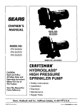
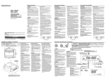
SEARS "HYDRO-GLASS ''®CENTRIFUGAL PUMPS
MODELS
390.262401,
390.262501,
AND 390.262601
9
10
11
2
14
12
13
SEARS "HYDRO-GLASS"®
MODELS
®
11
12
13
14
15
16
17
18
O
390.262501,
Part
Description
Key
No.
1
1A
2
3
4
5
6
7
8
9
10
390.262401,
CENTRIFUGAL
Motor
Motor Canopy
Slinger
Priming Plug 1/2"NPT
Tank Body Back Half Complete (Includes No. 3)
"O" Ring
Seal Plate Insert
Shaft Seal for %" Shaft
impeller
Diffuser
Screw #8-32 RH (4 Required)
Lockwasher #8
"V" Clamp
Tank Body Front Half (Includes No. 13)
Drain Plug 1,4NPT
"O" Ring
Base
PUMPS
AND 390.262601
390.262401
115/230V
60Cy/1Ph
1HP
390,262501
115/230V
60Cy/1Ph
1½ HP
390.262601
230V
60Cy/1Ph
2 HP
J218-596AC
U18-1235
C69-2
J218-601AC
U18-1235
C69-2
J218-880AC
U18-1235
C69-2
L276-35P1
U9-389
J3-2
2784
C105-138PBB
C1-258PA
U30-542SS
L276-35P1
U9-389
J3-2
2784
C105-137PH
C1-258PB
U30-869SS
L276-35P1
U9-389
J3-2
2784
C105-137PJ
C1-258P
U30-869SS
C19-54SS
C176-53P
C19-54SS
C176-53P
C19-54SS
C176-53P
YrW
U9-226
J104-9C
U43-11ZP
• U36-37ZP
C35-5
F642-7985
Washer 5/16 (4 Required)
Nut 5/16-18 (4 Required)
Rubber Pad
Owner's Manual
• Not illustrated,
• * Purchase Locally
13
U9-226
J104-9C
U43-11ZP
U36-37ZP
C35-5
F642-7985
U9-226
J104-9C
U43-11ZP
U36-37ZP
C35-5
F642-7985
"HYDRO-GLASS"®
SELF-PRIMING
CENTRIFUGAL PUMP
Now that you have purchased
your Centrifugal
Pump, should a need ever exist for repair parts or
service, simply contact any Sears Service Center. Be
sure to provide
visit.
all pertinent
facts when you call or
The Model Number
of your Centrifugal
Pump will
be found attached to the side of the pump body.
WHEN ORDERING
REPAIR PARTS, ALWAYS
THE FOLLOWING INFORMATION:
GIVE
•
PART NUMBER
•
PART DESCRIPTION
•
MODEL
•
NAME OF ITEM
NUMBER
All parts listed
Service Center.
may
be ordered
from
any
Sears
If the parts you need are not stocked locally, your
order will be electronically
transmitted
to a Sears
Repair Parts Distribution
Center for handling.
When Sears arranges
the installation,
you can be
sure the job is done right. We will arrange
for
professional
workmanship
. . . and we'll take care
of the entire project. What's more, during installation you get insured protection
. . . against property
damage and also against accidents to workmen. All
you have to do is talk to your Sears salesperson or
call your nearest Sears store today for detailed
information.
Sears, Roebuck and Co., Chicago,
Form No. F642-7985
(Rev. 9/90)
i11.60684 U.S.A.