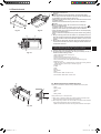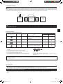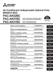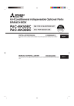
1
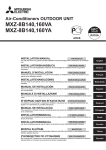
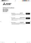
Contents
1. Safety precautions..............................................................................................2
2. Selecting a location for installation.....................................................................2
3. Confirming supplied accessories........................................................................3
4. Dimensions and required servicing space of Branch Box..................................3
5. Refrigerant piping...............................................................................................4
6. Mounting the Branch Box...................................................................................5
7.Installing refrigerant piping.................................................................................5
8. Installing drain piping..........................................................................................6
9.Electrical work....................................................................................................7
10.Test run..............................................................................................................9
This installation manual is only for the branch box installation. In installing the indoor units and outdoor units, refer to the installation manual attached to
each unit.
1. Safety precautions
► Before installing the unit, make sure you read all the “Safety precautions”.
► Please report to your supply authority or obtain their consent before
connecting this equipment to the power supply system.
Warning:
Describes precautions that must be observed to prevent danger of injury or
death to the user.
Caution:
Describes precautions that must be observed to prevent damage to the unit.
Warning:
• Ask a dealer or an authorized technician to install the unit.
• For installation work, follow the instructions in the Installation Manual and
use tools and pipe components specifically made for use with refrigerant
specified in the outdoor unit installation manual.
• The unit must be installed according to the instructions in order to minimize
the risk of damage from earthquakes, typhoons, or strong winds. An incorrectly installed unit may fall down and cause damage or injuries.
• The unit must be securely installed on a structure that can sustain its
weight.
• If the air conditioner is installed in a small room, measures must be taken
to prevent the refrigerant concentration in the room from exceeding the
safety limit in the event of refrigerant leakage. Should the refrigerant leak
and cause the concentration limit to be exceeded, hazards due to lack of
oxygen in the room may result.
• Ventilate the room if refrigerant leaks during operation. If refrigerant comes
into contact with a flame, poisonous gases will be released.
• All electric work must be performed by a qualified technician according to
local regulations and the instructions given in this manual.
• Use only specified cables for wiring.
• The terminal block cover panel of the unit must be firmly attached.
• Use only accessories authorized by Mitsubishi Electric and ask a dealer or
an authorized technician to install them.
After installation work has been completed, explain the “Safety Precautions,” use,
and maintenance of the unit to the customer according to the information in the
Operation Manual and perform the test run to ensure normal operation. Both the
Installation Manual and Operation Manual must be given to the user for keeping.
These manuals must be passed on to subsequent users.
: Indicates a part which must be grounded.
Warning:
Carefully read the labels affixed to the main unit.
• The user should never attempt to repair the unit or transfer it to another location.
• After installation has been completed, check for refrigerant leaks. If refrigerant leaks into the room and comes into contact with the flame of a heater or
portable cooking range, poisonous gases will be released.
• Be sure to connect the power supply cords and the connecting wires for the
indoor units, outdoor units, and branch boxes directly to the units (no intermediate connections). Intermediate connections can lead to communication
errors if water enters the cords or wires and causes insufficient insulation
to ground or a poor electrical contact at the intermediate connection point.
(If an intermediate connection is necessary, be sure to take measures to
prevent water from entering the cords and wires.)
Caution:
• Make sure that the refrigerant pipes are well insulated to prevent condensation. Incomplete insulation may cause condensation on the surface of
pipes, wetting of the ceiling, floor and other important properties.
• Make sure that the drainage pipe is carried out correctly following this manual and that it is insulated in order to prevent condensation. Any deficiency
caused by piping may result in water leakage, wetting of the
ceiling, floor and other personal properties.
2. Selecting a location for installation
* The branch box is only for indoor use.
Please attach the special optional cover (PAC-AK350CVR-E) to install the
branch box in the outdoors.
• Ensure that the branch box is installed in a location which facilitates servicing
and maintenance. (ensure that the required maintenance hole or service space
is available).
• Do not install near bedrooms. The sound of refrigerant flowing through
the piping may sometimes be audible.
• Ensure that it is located where noise in operation will not be a problem.
After power is supplied or after an operation stop for a while, a small
clicking noise may be heard from the inside of the branch box. The electronic expansion valve is opening and closing. The unit is not faulty.
• Determine the route of refrigerant piping, drain piping, and electrical wiring beforehand.
• Ensure that the location of the installation is such that the length of refrigerant
piping is within the specified limits.
• Ensure that the unit is out of reach of children at least 1.8 m above the floor.
• Do not install in location that is hot or humid for long periods of time.
• Ensure that the branch box is installed above the ceiling of corridor, bath room,
etc., where persons are not regularly there (Avoid installing at around center of
the room.) for maintenance.
• Ensure that the location of the installation is such that the down-gradient of the
drain piping is greater than 1/100.
* Ensure that the unit is installed in a location able to support its weight.
Warning:
Ensure that the unit is installed firmly in a location able to support its weight.
If the installation is of insufficient strength the unit may fall, resulting in injury.
BG79U439K10_en.indd
2
2013/02/01 (金)
午前 9:15:13
3. Confirming supplied accessories
3.1. Check the Branch Box accessories and parts
Accessory name
Washer (with insulation)
Washer
1
2
Q’ty
4
4
For refrigerant piping joint
: Type A
Accessory name
Pipe cover (Liquid)
Pipe cover (Gas)
Pipe cover (Liquid)
Pipe cover (Gas)
Joint cover (Liquid)
Joint cover (Gas)
Band
3
4
5
6
7
8
9
Q’ty
1
1
5
5
3
3
24
TO OUTDOOR UNIT
TO OUTDOOR UNIT
TO INDOOR UNITS
TO INDOOR UNITS
For drain pipe
: Type B
Accessory name
Drain hose
Band
0
1
Fig. 3-1
Q’ty
1
2
Type A or Type B
4. Dimensions and required servicing space of branch box
Optional different (deformed) joints
A
* Please connect 2 indoor units or more with one system.
* 1-2 branch boxes may be connected to one outdoor unit.
* Suspension bolt : W3/8 (M10)
* Refrigerant pipe flared connection
B
* The piping connection size differs according to the type and capacity of
indoor units. Match the piping connection size for indoor unit and branch
box. If the piping connection size of branch box does not match the piping connection size of indoor unit, use optional different-diameter (deformed) joints to the branch box side. (Connect deformed joint directly to
the branch box side.)
* When connecting P100 indoor unit(s), attach the optional Y-shaped connection pipe to the branch box. (The Y-shaped connection pipe is intended for use with PAC-AK52BC/PAC-AK53BC branch box only. )
Fig. 4-1
Connected pipe diameter
mm
ø9.52 → ø12.7
ø12.7 → ø9.52
ø12.7 → ø15.88
ø6.35 → ø9.52
ø9.52 → ø15.88
Model name
MAC-A454JP
MAC-A455JP
MAC-A456JP
PAC-493PI
PAC-SG76RJ-E
Diameter A
mm
ø9.52
ø12.7
ø12.7
ø6.35
ø9.52
Diameter B
mm
ø12.7
ø9.52
ø15.88
ø9.52
ø15.88
Optional Y-shaped connection pipe for P100 indoor unit
For use with PAC-AK52BC/PAC-AK53BC only
A
B
Fig. 4-2
Connected pipe diameter
mm
ø6.35 → ø9.52
ø9.52 → ø15.88
Model name
Liquid
Gas
PAC-AK52YP-E
Diameter A Diameter B
mm
mm
ø6.35
ø9.52
ø9.52
ø15.88
PAC-AK51BC/PAC-AK52BC/PAC-AK53BC (5-branch type)
(mm)
320
A Suspension bolt pitch
B To indoor unit
C Flexible drain hose (Accessory)
D Drain pipe connection (VP-16)
E To outdoor unit
F Service panel (for LEV, THERMISTOR)
G 3-WIRE BAND
H Electric cover
I 3-electric wire inlet
J Terminal block (to indoor unit)
K Terminal block (to outdoor unit)
* Ensure that the branch box is installed as shown on the below drawing. Leg must
be located on top. Otherwise drainage will not be properly performed.
PAC-AK51BC/PAC-AK52BC/PAC-AK53BC (Fig.4-3)
Liquid pipe
Gas pipe
1/4 F
3/8 F
1/2 F
5/8 F
3/4 F
12
S1
S2
S3
S1
S2
S3
S3
D
ø6.35
ø9.52
E
ø6.35
ø12.7
To outdoor unit
ø9.52
ø15.88
ø6.35
ø9.52
ø12.7
ø15.88
ø19.05
S1
S1
S2
S2
S3
TB3A
TB2B
198
C
ø6.35
ø9.52
TB3C TB3B
S2
A
B
ø6.35
ø9.52
S1
A
B
B
39
S3
C
C
280
50 34
S2
D
D
79
S1
E
E
95
61
TB3E TB3D
65 39
91
73
68 35 70
450
55
A
ø6.35
ø9.52
Drain hose size : O.D. 20 (VP16)
Conversion formula
24
402
Suspension bolt: W3/8 (M10)
Refrigerant pipe flared connection
S3
75
25
75
25
75
25
75
21
200
23
Type A
ø20
25
ø20
25
200
Type B
BG79U439K10_en.indd
3
Fig. 4-3
2013/02/01 (金)
午前 9:15:13
4. Dimensions and Required Servicing Space of Branch Box
PAC-AK31BC/PAC-AK32BC (3-branch type)
(mm)
320
PAC-AK31BC/PAC-AK32BC (Fig.4-4)
Suspension bolt: W3/8 (M10)
Refrigerant pipe flared connection
Liquid pipe
Gas pipe
A
ø6.35
ø9.52
B
ø6.35
ø9.52
C
ø6.35
ø9.52
To outdoor unit
ø9.52
ø15.88
24
402
Drain hose size: O.D.20 (VP16)
12
450
205
91
73
39
S2
S3
S1
S2
S2
S3
TB3A
S1
TB2B
198
S1
A
TB3C TB3B
A
B
68 35 70
280
50 34
S3
B
79
S2
C
C
95
61
S1
65 39
S3
75
25
21
200
23
75
Type A
ø20
25
ø20
25
200
Type B
*1
Min.
250
Min. 50
450
Min. 250
280
180-200
Fig. 4-5
B *3
Fig. 4-6
Min.
250 A
*2
(2)
198
(1)
Min.30
Fig. 4-4
4.1. Space required for installation and servicing
(1) Front View (Fig. 4-5)
A Branch box
B On the side of piping
(2) Side View (Fig. 4-6, Fig. 4-7)
C For indoor installations
D Ceiling board
E Maintenance hole
F PCB side
*1: A minimum 350 mm is required for 90° bends in refrigerant piping.
Note:
When using the PAC-AK52BC/PAC-AK53BC branch box to connect P100
indoor unit(s), the following procedure is required.
1. Connect the Y-shaped connection pipe end(s) to the indoor unit(s).
2. Mount the branch box.
3. Connect the Y-shaped connection pipe ends to the branch box.
450
Fig. 4-7
*2:
is “ Min. 200 mm ” <recommendation>.
(Premise: The slope of drain piping is securable 1/100 or more. Required
200 mm or more, when not securable.)
In the case of less than 200 mm (for example
is 100 mm), the exchange work
of Branch box from a maintenance hole becomes difficult (Only exchange work
of a PCB, linear expansion valve coils, sensors and drain pan is possible).
(3)
*3:
Min.250
Fig. 4-8
is “
600 mm ” <recommendation>.
In the case of “ 450”, prepare a maintenance hole at a PCB side (as it is shown
in Fig. 4-7), and “Min. 300 mm” is needed as distance
.
In the case of less than 300 mm (for example
is 100 mm), the exchange
work of Branch box, linear expansion valve coils, sensors, and drain pan from a
maintenance hole becomes difficult (Only exchange work of a PCB is possible).
(3) Top View (Fig. 4-8)
G Refrigerant piping
H When facing in the opposite direction to the refrigerant piping.
5. Refrigerant piping
* Always follow the specifications written in the installation manual of the outdoor unit. Exceeding these requirements may cause reduced performance of the
equipment, and malfunctions.
BG79U439K10_en.indd
4
2013/02/01 (金)
午前 9:15:14
6. Mounting the Branch Box
D
()
(mm)
Min. 50
Min. 50
Min.30
A
*
Fig. 6-1
Wall mount
Wall
* Purchase an appropriate
bracket locally if the unit
is to be mounted on a
wall.
7. Installing refrigerant piping
øA
► Connect the liquid and gas pipes of each indoor unit to the same end connection numbers
as indicated on the indoor unit flare connection section of each Branch Box. If connected to
wrong end connection numbers, it doesn’t work normally. (Fig. 7-1)
► When connecting indoor units, make sure to connect refrigerant pipes and connection wires
to the appropriate connection ports marked with matching alphabets. (Ex. A, B, C, D, E)
► When connecting P100 indoor unit(s) by using PAC-AK52BC/PAC-AK53BC, use Y-shaped
connection pipe(s) and perform the following piping. (Fig. 7-2)
When a single P100 indoor unit is wired to TB3A, connect the Y-shaped connection pipe
ends to Port A + B.
When two P100 indoor units are wired to TB3A and TB3C respectively, connect the Y-shaped
connection pipe ends to Port A + B and Port C + D.
For details, refer to the installation manual of the Y-shape connection pipe (PAC-AK52YP-E).
Note:
Be sure to mark all the local refrigerant piping (liquid pipes, gas pipes, etc.) for each indoor unit
designating clearly which room it belongs in. (Ex. A, B, C, D, E)
► List indoor unit model names in the name plate on the control box of Branch Box (for identification purposes).
.4
R0
90° ± 0.5°
45° ± 2°
0.8
-R
Flare cutting dimensions
Flare nut tightening torque
Fig. 7-1
A Flare cutting dimensions
Table 1
Copper pipe O.D.
(mm)
ø6.35
ø9.52
ø12.7
ø15.88
Flare dimensions
øA dimensions (mm)
8.7 - 9.1
12.8 - 13.2
16.2 - 16.6
19.3 - 19.7
Port B
Port A
(4) Fully tighten the nuts (check ceiling height).
(5) Use a level to adjust the branch box to the horizontal.
A When unit is hung and nuts tightened
B Suspension bolt
C Nuts
D Washer (with cushion) 1
E Ensure that cushion faces downwards
F Washer (without cushion) 2
G Nut (procure locally)
H Suspension bolt
I Ensure that this face is always installed upwards.
J Ceiling board.
Note:
* Refer to “4-1”.
Caution:
• Always install the unit horizontally.
• This unit may be installed suspended from the ceiling.
• This unit may only be installed vertically, as shown in the diagram below.
(Side
is facing up.)
• Incorrect installation may result in the drain overflowing.
Fig. 6-2
(1) Install the suspension bolts (procure locally) at the specified pitch (Fig. 4-3, 4-4).
(2) Fit the washers and nuts (1, 2, procure locally) to the suspension bolts.
(Fig. 6-1)
(3) Hang the unit on the suspension bolts.
Note:
When using PAC-AK52BC/PAC-AK53BC to connect P100 indoor unit(s), ensure that the Y-shaped connection pipe(s) is(are) connected to the indoor
unit(s) before mounting the branch box.
► To prevent water dripping from the refrigerant piping, install sufficient
thermal insulation.
► When using commercially available refrigerant piping, ensure that both
liquid and gas piping are wrapped with commercially available thermal
insulation materials (insulation materials at least 15 mm thick and able
to withstand temperatures in excess of 120 °C).
► Refer to the installation manual of the outdoor unit when creating a
vacuum and opening or closing valves.
(1) Remove the flared nuts and caps from the branch box.
(2) Flare the ends of the liquid and gas piping, and apply refrigeration oil (procure
locally) to the flared seat.
(3) Connect the refrigerant piping immediately. Always tighten the flared nuts to the
torque specified in the table below using a torque wrench and double spanner.
(4) Press the pipe covers 3 and 5 on the liquid piping against the unit and wrap
to hold in place.
(5) Press the pipe covers 4 and 6 on the gas piping against the unit and wrap to
hold in place.
(6) Apply the supplied bands 9 at a position 10 - 20 mm from each end of the
pipe covers ( 3 4 5 6 ).
(7) If the indoor unit is not connected, fit the supplied pipe covers (with caps, 7
and 8) to the branch box refrigerant piping connections to prevent condensation dripping from the pipes.
(8) Clamp the pipe covers ( 7 8 ) in place with the supplied bands 9.
B Flare nut tightening torque
Table 2
Fig. 7-2 Fig. 7-3
BG79U439K10_en.indd
5
Fig. 7-4
Copper pipe O.D. (mm)
ø6.35
ø6.35
ø9.52
ø9.52
ø12.7
ø12.7
ø15.88
ø15.88
Flare nut O.D. (mm)
17
22
22
26
26
29
29
36
Tightening torque (N·m)*
14 - 18
34 - 42
34 - 42
49 - 61
49 - 61
68 - 82
68 - 82
100 - 120
* 1N·m
10 kgf·cm
2013/02/01 (金)
午前 9:15:14
7. Installing refrigerant piping
Note:
A special flare nut (optional or attached to the indoor unit) is needed to
some indoor units.
Please refer to the installation manual of outdoor unit and indoor unit for
details.
(mm)
10~20
E Section of connection (Fig. 7-4)
F Band 9
G Pipe covers 3 4 5 6
H Tighten
J Refrigerant piping
L Thermal insulation for refrigerant piping
► Use the following procedures for indoor connection part which indoor
unit is not connected. (Fig. 7-5)
30~50
Fig. 7-5
(1) In order to prevent refrigerant leaks, make sure that the flare nuts are tightened
according to the specified torques* in Table 3.
* Refrigerant may also leak if the flare nuts are tightened more than the specified torques.
(2) In order to prevent condensation, install the pipe covers 7 8 and fasten them
with the supplied bands 9 .
Caution:
Tighten the flare nut with a torque wrench in the specified method.
Overtightening will cause the flare nut to crack and it will cause refrigerant
leakage over a period of time.
C Apply refrigeration oil to the entire (Fig. 7-3) surface of the flared seat.
D Basically use flared nuts fitted to the body (commercially available flared nuts
may crack).
Table 3
Diameters of branch box openings for
connecting indoor units (mm)
ø6.35
ø9.52
ø12.7
Tightening torque
(N·m)
13 ± 2
30 ± 2
50 ± 2
► Refrigerant charge:
Refer to the installation manual of the outdoor unit.
Use only R410A refrigerant (use of other refrigerants may cause troubles).
8. Installing drain piping
(mm)
Type A
200
23
20
11
10
11
Type B
200
20
11 10 11
10 to 20
10 to 20
Fig. 8-1
• To ensure that the drain piping has a down-gradient (greater than 1/100),
do not make traps or humps in piping.
• Install thermal insulation to prevent condensation dripping.
• Ensure that the horizontal length (not diagonal length) of drain piping does not
exceed 20 m. If the drain piping extends over a significant distance, install supports to ensure that the piping does not sag. Do not fit air bleed pipes under
any circumstances (water may exit from air bleed pipes).
• Do not fit odor traps at drain piping outlets.
• Install drain outlets in locations where odors will not present problems.
• Do not place drain piping directly in drains which may contain sulfurous gases.
• Drain piping may be installed in any direction provided the above requirements
are followed.
• Keep bends of attached drain hose to a maximum of 45°.
(1) Apply PVC adhesive (procure locally) to the drain connection on the branch
box and push the attached drain hose 0 onto the connection as far as it will
go. (Fig. 8-1)
(2) Insert a hard PVC pipe (VP-16, procure locally) into the attached drain hose
0 and glue it together and fix it. (Fig. 8-1)
A VP-16 procured locally
B Thermal insulation
(3) Fit a band 1 to the attached drain hose 0 (Fig.8-1)
(4) Ensure that the drain piping down-gradient is greater than 1/100. (Fig. 8-2)
C Supports
D Down-gradient greater than 1/100.
E Thermal insulation
Note:
The drain hose is available in either Type A or Type B.
The installation methods are different between Type A and Type B.
1.5 to 2 m
25 cm
Fig. 8-2
BG79U439K10_en.indd
6
2013/02/01 (金)
午前 9:15:15
9. Electrical work
► Cautions for electrical work.
Fig. 9-1
S1
S2
S2
S3
S3
S1
S1
S2
S2
S3
S3
TB3E TB3C
S1
TB3D TB3B
S2
S2
S3
S3
TB3A
S1
TB2B
S1
Caution:
• Be sure to establish an earth. Do not earth the unit to a utility pipe,
arrester, or telephone earth.
Incomplete earth may cause electrical shock. A high surge current from
lightning or other sources may cause damage to the air conditioner.
• Use the specified electrical wiring and ensure that it is connected properly,
and that it is not under tension.
Failure to follow these requirements may result in broken wiring, heating,
or fire.
► Wiring connecting branch box and outdoor unit, and branch box and indoor units, functions as both power supply and signal cable. Connect this
wiring in accordance with the terminal block numbers to ensure correct
polarity.
► Ensure that the appropriate refrigerant piping and electrical wiring are
connected to each indoor unit. Incorrect wiring will interfere with the correct operation of the unit.
Fig. 9-2
Warning:
• Always use dedicated circuits with breakers, and at the rated voltage.
Power supply circuits with insufficient capacity, and bad workmanship during installation, may result in electric shock or fire.
• Always ensure that electrical wiring inlets are sealed when the branch box
is installed outdoors.
Rainwater on the terminal blocks may result in fire or malfunction.
► Connect refrigerant pipes and connection wires to the appropriate ports
marked with matching alphabets (Ex. A, B, C, D, E) on this unit.
► Always fix each ground wire separately with a ground screw.
► To prevent that wiring installed in the ceiling is chewed by rats etc., it
should be installed in wiring conduit.
1. Remove the screws in the cover. (Fig. 9-1)
2. Remove the cover.
3. Pass the wiring into the branch box. (Fig. 9-2)
4. Fix each wire in place with a wiring clamp. (Fig. 9-3)
5. Firmly connect each wire to the appropriate terminal block. (Fig. 9-3)
6. Replace the cover.
7. When the branch box is installed outdoors, ensure that the wiring inlets are
sealed with putty to prevent entry of rainwater. (Fig. 9-2)
A Electric cover
B 3-Bush
C Seal
D Wiring
E BC controller
F Band
G Terminal block: TB2B <To outdoor unit>
H Terminal block: TB3A-TB3E <To indoor unit>
Fig. 9-3
9.1. When using wiring conduit (Fig. 9-4)
Replace the horizontal cover when the wiring conduit has been fixed in place.
A Cover
B Wiring conduit
C Washer
D Nut
E Wiring conduit
*
Wiring conduit of up to 1" OD may be used.
(1) When using 1" OD wiring conduit, remove the bush and fix to the branch box.
Remove the horizontal cover while fixing to the branch box.
(2) When using wiring conduit of 3/4" OD or smaller, notch the bush and insert the
wiring conduit approximately 100 mm into the branch box.
* Replace the horizontal cover when the wiring conduit has been fixed in place.
Fig. 9-4
BG79U439K10_en.indd
7
2013/02/01 (金)
午前 9:15:15
9. Electrical work
TB3A
S1
S2
S3
Outdoor unit
(A)
(A)
Circuit
breaker
L
N
S1
S2
S3
(B)
9.2. External wiring procedure (Fig. 9-5)
Branch box#1
(5-branch type)
<Example 1>
(in case of 2-branch boxes)
TB2B
S1
S2
S3
(C)
TB3B
S1
S2
S3
TB3C
S1
S2
S3
TB3D
S1
S2
S3
TB3E
S1
S2
S3
(C)
TB3A
S1
S2
S3
TB2B
S1
S2
S3
TB3B
S1
S2
S3
TB3C
S1
S2
S3
(D)
E Power supply: Single phase 220/230/240 V, 50 Hz 220 V, 60 Hz
Indoor unit
S1
S2
S3
(D)
S1
S2
S3
(D)
S1
S2
S3
(D)
S1
S2
S3
(D)
S1
S2
S3
A ROOM
B ROOM
C ROOM
(A) Main
power line
D ROOM
E ROOM
Indoor unit
(D)
S1
S2
S3
(D)
S1
S2
S3
(D)
S1
S2
S3
Note:
1 Power supply input: Outdoor unit only. Connect the lines (C), (D) in accordance with the terminal block names to ensure correct polarity.
2 As for lines (C), S1 and S2 are for connecting the power source.
And S2 and S3 are for signals. S2 is a common cable for the power source
and signal.
F ROOM
G ROOM
H ROOM
6.0 mm²
Wire diameter
Breaker
(B) Earth (C) Signal line/ (D) Signal line/ Interrupting Performance
line
Earth line
Earth line
current
characteristic
1.5 mm² *2/ 1.5 mm²/
6.0 mm²
*1
*1
Min. 1.5 mm² Min. 1.5 mm²
When using twisted wire for the wiring, the use of round terminal is required.
*1 Refer to the installation manual of the outdoor unit.
*2 If 1.5 mm² used, Max. 45 m (“Outdoor unit - Branch box #1” plus “Branch box #1
- Branch box #2”). If 2.5 mm² used, Max. 55 m
(When connecting indoor unit of PEAD series)
If 1.5 mm² used, Max. 30 m (“Outdoor unit - Branch box #1” plus “Branch box #1
- Branch box #2”).
If 2.5 mm² used, Max. 50 m
If 3.5 mm² used, and S3 separated, Max. 55 m
Use one cable for S1 and S2 and another for S3 as
shown in the picture.
Notes: 1. Wiring size must comply with the applicable local and national
code.
2. Power supply cords and Indoor unit/Branch box/Outdoor unit connecting cords shall not be lighter than polychloroprene sheathed
flexible cord. (Design 60245 IEC 57)
3. Install an earth line longer than power cables.
Branch box#2
(3-branch type)
Fig. 9-5
9.3. Wiring to P100 indoor units (Fig. 9-6)
<Example2>
(in case of wiring to P100 indoor unit(s))
•When wiring P100 indoor unit(s), only use PAC-AK52BC/PAC-AK53BC branch
box.
• When wiring a single P100 indoor unit, use TB3A.
Branch Box
(PAC-AK52BC only)
TB3A
S1
(A)
(A)
E
Circuit
breaker
(D)
Indoor unit
S1
S2
S2
S3
S3
TB2B
S1
TB3B
S1
S1
S2
S2
S2
S2
S3
S3
S3
S3
L
A ROOM
P100
Indoor unit
N
(B)
S1
(C)
TB3C
(D)
S1
S1
S2
S2
S3
S3
TB3D
S1
S2
S3
TB3E
S1
S2
S3
B ROOM
P100
Indoor unit
Notes:
•When wiring a single P100 indoor unit, ONLY use TB3A.
If a single P100 indoor unit is wired to the other terminal block, an alarm
will be activated, and the indoor unit will not operate.
•When a single P100 indoor unit is wired to TB3A, do not wire any indoor
unit to TB3B. Otherwise, an alarm will be activated, and the indoor unit
will not operate.
•TB3C, TB3D, and TB3E are available for wiring of indoor units that are
not P100.
•When wiring two P100 indoor units, use TB3A and TB3C.
Notes:
•When wiring two P100 indoor units, ONLY use TB3A and TB3C.
If two P100 indoor units are wired to the other terminal blocks, an alarm
will be activated, and the indoor units will not operate.
•When two P100 indoor units are wired to TB3A and TB3C respectively,
do not wire any indoor unit to TB3B or TB3D. Otherwise, an alarm will be
activated, and the indoor unit will not operate.
Fig. 9-6
BG79U439K10_en.indd
8
2013/02/01 (金)
午前 9:15:15
9. Electrical work
Warning:
In case of A-control wiring, there is high voltage potential on the S3 terminal caused by electrical circuit design that has no electrical insulation between power
line and communication signal line. Therefore, please turn off the main power supply when servicing. And do not touch the S1, S2, S3 terminals when the power
is energized. If isolator should be used between outdoor unit and branch box/indoor unit and branch box, please use 3-poles type.
Power supply
Isolator (Switch)
S1
3 poles isolator (Switch)
S1
S1
S1
Outdoor unit S2
S2
Branch
S2
box
S2
S3
S3
S3
S3
“A-control”
Indoor unit
Caution:
After using the isolator, be sure to turn off and on the main power supply to reset the system. Otherwise, the outdoor unit may not be able to detect the
branch box(es) or indoor units.
WIRING SPECIFICATIONS
(OUTDOOR-BRANCH BOX CONNECTING CABLE)
Cross section of cable
Round
Flat
Wire size (mm²) Number of wires
Polarity
Other
2.5
3
Clockwise : S1-S2-S3
* Pay attention to stripe of yellow and green
2.5
3
Not applicable
(Because center wire has no cover finish)
1.5
4
2.5
4
From left to right : S1-Open-S2-S3
Flat
Round
Clockwise : S1-S2-S3-Open
*Connect S1 and S3 to the opposite angle
*1 :Power supply cords of appliances shall not be lighter than design 60245 IEC or
60227 IEC.
*2 : In case that cable with stripe of yellow and green is available.
*3 : In case of regular polarity connection (S1-S2-S3), wire size is 1.5 mm².
*4 : In case of regular polarity connection (S1-S2-S3).
*5 : In the flat cables are connected as this picture, they can be used up to 55 m.
When connecting indoor unit of PEAD series, they can be used up to 50 m.
L (m)*6
When PEAD-series
units are included
(50)
*2
(50)
*2
Not applicable
*5
Not applicable
*5
(45)
*3
(30)
*3
(55)
*4
(50)
*4
(3C Flat cable s 2)
S1
S2
S3
*6 : Mentioned cable length is just a reference value.
It may be different depending on the condition of installation, Humidity or
materials, etc.
Be sure to connect the outdoor-branch box/indoor-branch box connecting cables directly to the units (no intermediate connections).
Intermediate connections can lead to communication errors if water enters the cables and causes insufficient insulation to ground or a poor electrical contact at the intermediate connection point.
10. Test run
• Refer to the “Test run” section of the installation manual of the indoor units and outdoor unit.
• When installation of the indoor unit, branch box, and outdoor unit is complete, begin test run to check for water leaks in the branch box.
• After power is supplied or after an operation stop for a while, a small clicking noise may be heard from the inside of the branch box. The electronic expansion valve is opening and closing. The unit is not faulty.
• Be sure to perform the test run for each indoor unit. Make sure each indoor unit operates properly following the installation manual attached to the unit.
• If you perform the test run for all indoor units at once, you cannot detect any erroneous connection, if any, of the refrigerant pipes and the indoor/outdoor unit connecting
wires.
BG79U439K10_en.indd
9
2013/02/01 (金)
午前 9:15:16
This product is designed and intended for use in the residential,
commercial and light-industrial environment.
The product at hand is • Low Voltage Directive 2006 / 95 / EC
based on the following • Electromagnetic Compatibility Directive 2004
EU regulations:
/108 / EC
Please be sure to put the contact address/telephone number on
this manual before handing it to the customer.
BG79U439K10
BG79U439K10_en.indd
10
HEAD OFFICE: TOKYO BLDG., 2-7-3, MARUNOUCHI, CHIYODA-KU, TOKYO 100-8310, JAPAN
Authorized representative in EU: MITSUBISHI ELECTRIC EUROPE.B.V.
HARMAN HOUSE, 1 GEROGE STREET, UXBRIDGE, MIDDLESEX, UB8 1QQ, U.K.
Printed in PRC
2013/02/01 (金)
午前 9:15:16