1
MODELNUMBER917o372290
oAssembly
oOperation
0
"
Maintenance
°Service
_,Adjustments
®Repair Parts
Caution:
Readand Follow
all SafetyRules
and Rnstructions
BeforeOperating
ThisEquipment
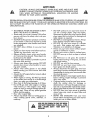
OWNER'SMANUAL
SAFETY
RULES
CAUTION:ALWAYS
WHERE
DISCONNECT
IT CANNOT
CONTACT
SPARK
PLUG WIRE
T
AND
PLACEWIRE
AO U T, O
SPARK PLUG TO PREVENT ACCIDENTAL
STAR-
IMPORTANT
FEDERAL REGULATIONS
REQUIRE OPERATOR PRESENCE BLADE STOP CONTROLS
TO MINIMIZE
THE
RISK OF BLADE CONTACT
INJURY, YOUR LAWN MOWER
IS EQUIPPED WITH SUCH CONTROLS.
DO
NOT ATTEMPT TO DEFEAT THE FUNCTION
OF THE OPERATOR
PRESENCE CONTROL
UNDER ANY
CIRCUMSTANCES.
o
•
o
o
o
o
°
o
o
o
o
o
o
o
°
BE CAREFUL-WHEN
NING THE BLADE
THE ENGINE
IS TURNING
Please read your owner's
manual.
IS RUNOnly allow
persons who know the safety rules to use your
lawn mower'.
DO NOT tie the operator presence control bar
to the handle_ Control must be free to permit
brake engagement
when handles and control
are released.
DO NOT allow children to use your lawn
mower.
Check your lawn mower over before each use.
Tighten any loose bolts, nuts, etc.
Remove all sticks, stones, wires, cans, boards,
etco from area to be mowed. These objects can
be thrown by the blade.
DO NOT allow children, bystanders or pets in
the area while mowing°
Always wear shoes when mowing_ DO NOT
operate lawn mower when barefoot or' wearing open sandals.
Always
wear safety glasses or eye shields
before starting your lawn mower and while
mowing°
Always shut off engine before trying to adjust
whee/heights.
When engine is running, DO NOT put hands
or feet under lawn mower or" in the discharge
chute, nor make any adjustments.
Stay clear of discharge
opening at all times.
Do not fill gas tank when engine is running,
when indoors or' when engine is hot. Allow
engine to cool for several minutes before filling gas tank_ Clean off any spilled gasoline
before starting engine.
Mow only in goodlight.
Always stop blade when not cutting grass or
when crossing
gravel
drive,
sidewalk,
or
roadway.
I
,_
i
o
o
o
o
o
o
o
•
o
o
°
o
o
•
DO NOT continue to run your lawn mower if
c_OU hit a foreign object.
Stop the engine,
isconnect the spark plug wire from the spark
plug, inspect the lawn mower for damage and
make repairs as required.
DO NOT use a damaged lawn mower. Always
have damage repaired
before mowing.
DO NOT run your lawn mower if it vibrates
too much. Stop engine and make repairs
Vibration
is an indication
of damage.
Never' use your lawn mower without proper'
guards or deflectors in place.
Always mow across a slope or inclined area.
DO NOT mow up or down a slope or inclined
areao
DO NOT mow in wet grass. Be careful of
footing when mowing in wet grass, use shoes
with good traction.
DO NOT run with the lawn mower'.
DO NOT run your lawn mower indoors° Exhaust gases are deadly poison.
Always disconnect the spark plug wire from
spark plug to prevent accidental starting when
transporting
or' storing your lawn mower' after
the mowing season.
DO NOT attempt to raise engine speed above
factory settings. Engine damage or personal
injury may result.
If a grass catcher' is used on your lawn mower,
check the catcher
often
for damage
or
deterioration°
it will wear through normal use.
Use only a recommended replacement catcher.
Always stop blade to remove or insta!l catcher.
DO NOT store your lawn mower or gasoline
where fumes may reach an open flame and
cause a fire.
DRAIN
THE GASOLINE
from your lawn
mower before transporting
your lawn mower
inside your car or other vehicle.
LOOKFOR THIS SYMBOLTO POINT OUT IMPORTANT SAFETYPRECAUTIONS.IT MEANS-- ATTENTION!!! BECOME ALERT!!! YOUR SAFETY IS
INVOLVED
..........
................................
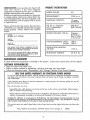
PBODUCT
SP[CBFICATUGNS
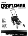
CONGRATULATIONS
on your purchase of a Sears Craftsman
Lawn
Mower.
It has been
designed,
engineered
and manufactured
to give you the best
possible dependability
and performance.
Should you experience any problem you cannot easily remedy, please contact your nearest Sears Service Center/Department.
We have competent, welltrained technicians and the proper tools to service
or repair this unit..
Please read and retain this manual,
will enable you to assemble
mower properly°
Always
RULES".
,, ,,,,,,,,,,,,,,,,,,,,,,,,i
HORSE
The instructions
POWER:
4.0
DISPLACEMENT:
10.49
GASOLINE
l oO.quart ,,
unteaaecll
CAPACITY:
SAE 30 or
OIL (21 oz. Capacity):
A.Pol. Classification
SG/SF/SE
and maintain your lawn
observe the "SAFETY
SPARK
i,
PLUG (GAP
cu. in.
(SAE10W30)
°030 in.):
MODEL
NUMBER 9t7o372290
Champion
RJ19-LM or
Sears 7_j 33312
or STD 361458
SERIAL
NUMBER
VALVE CLEARANCE:
DATE OF
PURCHASE
Intake:
Exhaust:
I
II II1' '111
I
.008 inn
°008 in,
I
THE MODEL AND SERIAL NUMBERS WILL BE
FOUND ON A DECAL ATTACHED TO THE REAR
OF THE LAWN MOWER HOUSING
SOLID STATE IGNITION
AIR GAP:
..0125 in.
YOU SHOULD RECORD BOTH SERIAL NUMBER
AND DATE OF PURCHASE AND KEEPIN A SAFE
PLACE FOR FUTURE REFERENCE.
BLADE
35-40
BOLT TORQUE:
ft.-Ibs..
MAIHT :NAHCE
AGREEMEHT
A Sears Maintenance
Agreement
is available
on this product.
Contact
your
nearest
Sears store for details_
CLISTOMEE
RESPONSRBlUTIES
"
o
Read and observe
°
Follow
the safety
rules°
Follow a regular schedule in maintaining,
the in s!ructions
under
"Maintenance"
caring for and using your lawn mower.
and "Storage"
sections of this Owner's
Manua...!..
OHEY[AR LIMIT[DWARBANTY
OH CRA[:TSMAH
POWEBMOWEP,
For one year from the date of purchase, when this Craftsman Lawn Mower is maintained, lubricated and tuned-u R
accordinq to the instructions I'n the owner's manual, Sears will repair, free of charge, any defect in material
and workmanship°
if this Craftsman Lawn Mower is used for commercial or rental purposes, this warranty
days from the date of purchase.
This warranty
applies for only 90
does not cover:
Expendable items which become worn during normal use, such as rotary mower blades, blade adapters,
belts, air cleaners and spark plug.
Repairs necessary because of operator abuse or negligence, including bent crankshafts and the failure to
maintain the equipment according to the instructions contained in the owner s manual°
WARRANTY
SERVICE 1S AVAILABLE BY RETURNING THE CRAFTSMAN POWER MOWER
NEAREST SEARS SERVICE CENTER/DEPARTMENT tN THE UNITED STATES_ THIS WARRANTY
ONLY WHILE THIS PRODUCT IS IN USE IN THE UNITED STATES.
This warranty
to state..
TO THE
APPLIES
gives you specific legal rights, and you may also have other rights which may vary from state
Sears, Roebuck and Company,
D/731CR,
3
Sears Tower, Chicago,
IL
60684
TABLEOF CONTENTS
.....................
SAFETY RULES
PRODUCT SPECIFICATIONS
......
CUSTOMER RESPONSIBILITIES
WARRANTY ..............
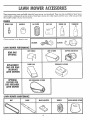
LAWN MOWER ACCESSORIES
ASSEMBLY ..............
OPERATION
.....
MAINTENANCE
...........
2
3
3
3
5
6,7
8-11
12-14
SERVICE AND ADJUSTMENT
STORAGE
......................
SERVICE RECOMMENDATIONS
TROUBLE SHOOTING
.......
REPAIR PARTS-LAWN
MOWER
REPAIR PARTS-ENGINE
.....
PARTS ORDERING/SERVICE
........
15,16
17
18
19
20-24
25-27
28
A
Adjustments:
Carburetor
,
Handle Height
Height of Cut
Air Filter:
Replacement
Assembly:
Handle
Grass Catcher
Accessories
15
16
9
Handle:
Adjustment
Assembly
Bracket
Knob
t6
.6
17
8
Repair/Replacement Parts
Responsibilities, Customer
20-24
3
14
6
6,7
5
Blade:
Replacement
Sharpening
Lubrication:
Engine
Brake Spring Brackets
Handle Bracket Mounting
Rear Door Hinge
Wheel Adjusters
_
Pins
t8
18
18
18
18
12
12
M
Controls:
Engine Zone Control Cable •
Operator Presence Control Bar
Customer Responsibilities
Engine:
Oil Cap
Oil Change
Oil Levet
Oil Type
Starting
Storage
10
8
3
.8
13
10
10
1t
17
F
Fuel:
Type
10
Storage
17
Maintenance:
Agreement
Air Filter
Blade Care/Replacement
Engine
Gear Case
Grass Catcher
Lubrication
Spark Plugs
Mowing Tips
2
15
16
18
14
3
11
1]
17
T
.3
14
12
13
t3
13
18
14
11
0
Oil:
Engine
10
Storage
17
Operation:
Operating Lawn Mower'
.
8-11
Operator Presence Control Bar
8
Options:
Attachments
5
4
Safety Rules
Service and Adjustments:
Carburetor'
Handle
Service Recommendation
Spark Plugs
Specifications
Starting the Engine:
Starter Handle_
Stopping the Engine
Storage
Trouble Shooting Chart
19
W
Warranty
Wheels:
Wheel Adjusters
3
9
These accessories were available when this lawn mower was produced, They are also available
at most Sears
retail outlets, catalog and service centers_ Most Sears stores can order repair parts for you, when you provide
the model number of your lawn mower,
ENGINE
SPARKPLUG
If lawn mower
AIR FILTER
MUFFLER
is an electric
GAS(:AN
ENGINEOIL
STABILIZER
start
LAWNMOWERPERFORh'iANCE
REARBAG
OPTIONAL
REPLACEMENT
BAGFORREAR
DISCHARGE
LAWN_OWERS
OPTIONAL
DUSTSHIELD
LEAFCATCHER
CLIPPING DEFLECTOR
PERMANEXCATCHER
FABRICBAG
SIDE DISCHARGECATCHER
CATCHER
FOR
SiDEDISCHARGE
LAWNt_OWER
LAWNMOWEBt_A_NTENANCE
BELT
BLADE
BLADEADAPTER
WHEELS
LAWN MOWER COVER
Your lawn mower has been assembledat
tory except
for' the grass catcher,.
The following
parts are included
the facOPERATOR
CONTROL
PRESENCE
BAR
- not assembled:
UPPER
1
1
1
1
Grass
Grass
Grass
Grass
Catcher'
Catcher
Catcher
Catcher'
1
Hardware
Top
Bottom
Handle
Frame
LIFT UP
UFT
With
UP
!?
Baffle
Package
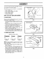
HOW TO S T-UP YOUR LAWN MOWER
TO UNFOLDHANDLE
LOWER
Remove handle padding holding operator presence
control bar to upper handle_
. Hold down operator presence control bar to upper handle to allow handle to move to mowing
position.
Raise handles until lower handle section locks into place in mowing position (See Fig. 1).
Raise upper handle section intoplace
on lower
handle and tighten one (1) handle knob.
o Release operator
presence
controt
bar' and
tighten remaining handle knob_
o Your lawn mower handle can be adjusted for your
mowing comfort. Refer to "Adjust Handle" in the
service and Adjustment
Section of this manual_
,NDLE
FIG. 1
TRUSS
HEAD SCREWS
#10_24 x 5t8"
CLAMP
o
/
CATCHER
TOP
# 10-24
TO ASSEMBLE
GRASSCATCHER
SCREWS
ACTUAL
CATCHER
FRAME
FIG. 2
SIZE
TOP HANDLE
1/4-20 x 3/4"
SCREW
#10-24 x 5/8"
SCREW
,'--,
t/4-20
k
PHILLIPS HEAD
SCREW
t/4-20
x 5/8"
SCREW
NOTE: The grass catcher for your lawn mower is suplied unassemMedo To assemble your grass catcher
Ilow steps below_
o Place grass catcher frame into catcher top as
shown in Fig_ 2_
• Put one (1) #10-24 x 5/8 truss head screw into
hole in catcher top and catcher frame using
#10-24 locknuL DO NOT TIGHTEN (See Fig. 2).
o Put three (3) # 10-24 x 5/8 truss head screws into
the catcher frame using #10-24 iocknuts. Use a
medium phillips screwdriver
to tighten screws
while holding the tocknut with an adjustable
or
3/8 wrench (See Fig° 2)_
1/4-20
LOCKNUT "-'-_(_
FIG. 3
x 5/8"
Y
TO
ASSEmblE
6RASS
CATCHER
ICO_TID)
..............................
•
Position round end of top handle into hole at rear
of handle recess (See Fig 3), The flat end of top
handle will fit into the square pocket at front of
handle recess° Put the I/4-20 x 5/8 screw through
the handle and catcher top, and install 1!4-20
Iocknut (See Fig. 3)_
o Use a medium phillips screwdriver
to tighten
screw while holding the Iocknut with an adjustable
or 7116 wrench (See Fig_ 3)°
o
_ .....................................
CATCHER
CATCHER
Position top half of catcher on the bottom half ISee
Fig 4)° Align the holes in sides of top and bottom halves of catcher°
..................................................................................................................
1/4-20 x 3f4"
TRUSS HEAD
SCREWS
TOP
BOTTOM
1 4 - 20 KEPS NUTS
START
Instal) the right front truss head 114-20 x 3/4
screw through the catcher and install one (1) 1/4
keps nut on the screw. DO NOT TIGHTEN
(See
Fig_ 4)_
• Install the other seven (7) screws and keps nuts,
• Use a medium phillips screwdriver
to tighten the
screws while holding the keps nut with an adjustable or 7116 wrench_
NOTE: Check all screws and nuts to be sure they are
tight,
HERE
o
FIG. 4
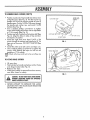
HINGE
BRACKET
TO ATTACHGRASSCATCHER
°
Lift rear door,
o
Hold catcher by handle and place catcher
onto hinge bracket (See Fig_ 5)°
Release rear door,
°
frame
REAR DOOR OPEN
o When grass catcher is removed from lawn mower,
rear door doses for safety°
FIG. 5
CAUTION: DO NOT RUN YOUR LAWN MOWER
°
NEVER ATTEMPT TO OPERATE THE LAWN
MOWER
WITH THE REAR DOOR REMOVED
OR PROPPED OPEN_
!
_o:_
T
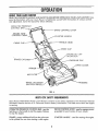
ENOWYOURLAWNMOW[R
READ THIS OWNER'S
MANUAL
AND
SAFETY RULES BEFORE OPERATING
pare the illustrations with your Lawn Mower to familiarize
and adiustmentso Save this manual For future reference,
OPERATOR
CONTROL
ENGINE
CONTROL
CABLE
yourself
YOUR LAWN
with the location
MOWER.
of various
Cam-
controls
PRESENCE
BAR---_..,.._
DRIVE
ZONE
CABLE,
CONTROL
;TARTER
HANDLE
HANDLE
CLIP
LEVER
CABLE
KNOB
CLIP
ENGINE OIL CAP
PSTICK
GRASS
CATCHER
INE CAP
COVER
PRIMER
AIR
FILTER
"HOUSING
WHEEL ADJUSTER
(ON EACH WHEEL)
FIG. 6
MELTSCPSCSAF[TYREQUHREM[NTS
Sears Rotary Walk-Behind
Power Lawn Mowers conform to the safety standards of the American
National
Standards
Institute and the U.S, Consumer Product Safety Commission,
The blade turns when the engine
is running.
OPERATOR PRESENCE CONTROL
BARheld down to the handle to start the engine.
to stop the engine.
must be
Release
DRIVE CONTROL
propelled forward
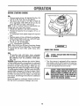
PRIMER - pumps additional fuel from the carburetor
to the cylinder' for use when starting a cold engine.
STARTER
8
HANDLE
LEVER - used to engage
motion of lawn mower.
o,used for starting
power'-
the engine.
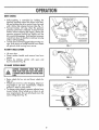
DRIVECONTROL
Self-propelling
is controlled
by holding
the
operator presence control bar down to the handle and pushing the drive control lever forward
until it clicks; then release the lever (See Fig_ 7)°
o Forward
motion will stop when the operator
presence control bar is released_ To stop forward
motion without stopping the engine, release the
operator
presence control bar slightly until the
drive control disengages_ Hold operator presence
control bar down to handle to continue mowing
without self-propelling.
o To keep drive control engaged when turning cor_
ners, push down on handle and Hft front wheels
off ground while turning lawn mower.
LPREBASE
\\'
TO ENGAGE
_\
DRIVE CONTROL
ORIVE
CONTROL
DISENGAGED
FIG. 7
TO EMPTYGRASSCATCHER
o
Lift rear
door.
o Grasp catcher handle and remove
mower_
o Empty
by shaking
catcher
with
downward
(See Fig 8)_
from
lawn
open
end
TO ADJUSTCUTTINGHEIGHT
:
FROM SPARKPLUG AND PLACEWIRE WHERE
IT CANNOTCOMEIN CONTACTWITH THESPARK
cAuTION: DISCONNECTSPARK PLUG WiRE
PLUG.
FIG. 8
o Raise wheels
for low cut and lower
wheels
for
high cut°
o Wheels are set in low cut for shipping_ Adjust cutting height to suit your requirements°
Medium
position is best for most lawns_
o To change cutting height, squeeze adjuster lever
toward wheel. Move wheel up or down to suit
your requirements.
Be sure all wheels are in the
same setting (See Fig. 9)°
LOWER
WHEELS
"-
-',._,
FIG. 9
RAISE WHEELS
FOR LOW CUT
T
OiL:
o
GASOLINE
FILLERCAP
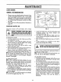
Remove engine oil cap with dipstick (See Fig, 10)
and fill to the FULL line on the dipstick.
Use about one (1) pint or 0.5 liters of SAE 30
oil or equivalent SAE 10W 30 oil can also be
used_ DO NOT use SAE 10W 40 oil.
NOTE: A 20 oz. bottle of Pennzoil SAE 30 Oil is included with your new lawn mower.
POUR OIL SLOWLY. DO NOT OVER FILL.
o The total oil capacity of your engine is 21 ozo or
0_62 liters°
° To read proper level, tighten engine oil cap each
time.
o Replace engine oil cap with dipstick and tighten.
Check oil level before each use, Add oil if neededo Fill to FULL line on dipstick°
The oil you use should meet:
A,P.I.. Classification SG/SFISE.
NOTE:After the first two (2) hours of mowing, change
the oil, and every 25 hours thereafter. You may need
to change the oil more often under dusty, dirty
conditions°
,ENGINE OIL CAP W/DIPSTICK
FIG. 10
ENGINe:
ZONECONTROL
I
GAS:
CAUTION: THEBLADETURNSWHENTHEENGINEI
IS RUNNING.
Fill gasofine
tank with fresh, clean unleaded
gasoline. DO NOT USE PREMIUM GASOLINE.
BE CAREFUL NOT TO OVERFILL TANK (SEE
FIG. 10).
WARNING: Experience indicates that alcohol blended fuels (called gasohol or using ethanol or methanol)
can attract moisture which leads to separation and
formation of acids during storage° Acidic gas can
damage the fuel system of an engine while in storage.
To avoid engine problems, the fuel system shouldbe
emptied before storage for 30 days or tonger_ Drain
the gas tank, start the engine and let it run until the
fuel lines and carburetor
are empty. Use fresh fuel
next season. See Storage Instructions for additional
information.
I
Your' lawn mower is equipped
with an operator
zone engine control which requires the operator
to be positioned
behind the lawn mower' handle
to start and operate the lawn mower_
CAUTION: FEDERAL
REGULATIONS
REQUIRETHE
ENGINE CONTROLINSTALLEDON THIS LAWN
MOWER IN ORDERTO MINIMIZE THE RISK OF
BLADECONTACTINJURY. DO NOT UNDERANY
CIRCUMSTANCES
ATTEMPTTO DEFEAT
THEFUNCTION OF THE OPERATORCONTROL.
Never use engine or carburetor
cleaner products in
the fuel tank or permanent damage may occur_
10
o When using a rear discharge
lawn mower in
moist, heavy grass, clumps of cut grass may not
enter the grass catcher. Reduce ground speed
(pushing speed) and/or run the lawn mower over
the area a second time°
If a trail of grass clippings is left on the right side
of a rear discharge
lawn mower,
mow in a
clockwise direction with a small overlap to collect the clippings on the next pass°
For side discharge
lawn mowers,
cutting in a
counter-clockwise
direction, starting at the outside
of the area to be cut, spreads grass clippings more
evenly and puts less load on the engine. To keep
clippings off of walkways, flower beds, etc., make
the first cuts in a clockwise direction°
To start a cold engine, push primer five (5) times
before trying to start. Use a firm push. This step
is not usually necessary when starting an engine
which has already
run for a few minutes.
Hold operator presence control bar down to the
handle and pull starter handle quickly. Do not
allow starter rope to snap back.
o To STOP engine, release operator presence control bar.
NOTE: In cooler weather
it may be necessary to
repeat priming steps. In warmer weather over prim_
ing may cause flooding and engine will not start. If
you do flood engine wait a few minutes before attempting to start and DO NOT repeat priming steps.
OWING TiPS
o
tect less grass. To prevent
cher off with water and
The vent holes in the baffle
catcher can become rifled
o Under certain conditions, such as very tall grass,
it may be necessary to raise the height of cut to
reduce
pushing
effort
and to keep from
overloading
the engine and _eaving clumps of
grass clippings°
o For extremely heavy cutting, reduce the width of
cut and raise the rear of the lawn mower housing one (1) whee_ adjuster
front for better discharge
Pores in cloth grass catchers can become filled
with dirt and dust with use and catchers wilt col-
use and the catcher
this, regularly hose catlet dry before using.
in back of a permanex
with dirt and dust with
will collect
less grass.
To prevent this, regularly
hose the catcher baffle
with water and let dry before using.
setting higher than the
of grass.
11
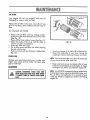
Once a year you should replace the spark plug,
air filter' and check blade for wear. A new spark
plug and air filter assures proper air-fuel mixture
andhelps your engine run better and last longer'.
You should check all fasteners and be sure they
are tight°
Follow the Service Recommendation Schedule on
page 18.
CRANKSHAFT
LOCKWASHER
____BLA
D E ADAPTER--_'_
BL_D£/B_D£ADAPT_R
CARE
FIG. 11
Your lawn mower will work better' with a sharp
blade.
j....................
CAUTION:
msc0 ma
Install the blade bolt with the Iockwasher and
hardened washer into blade adapter
and
crankshaft (See Fig. 11).
o Use block of wood between blade and lawn
mower housing and tighten the blade bolt, turning clockwise.
o The recommended tightening torque is 35-40 ft.
ibs.
Torque wrenches are available at most Sears
stores and through the catalog.
IT CANNOT
COMEINCONTACT
WITHTHESPARK
PLUG
TO REMOVE BLADE:
o Turn lawn mower on its side. Make sure air' filter
and carburetor
are up,
Use block of wood between blade and lawn
mower housing to prevent blade from turning
when removing
the blade bolt.
o Protect your hands with gloves and!or
wrap
blade with heavy cloth,
o Remove blade bolt by turning counter-clockwise.
Use a 9t16"
box or open-end wrench.
o Remove blade and attaching
hardware
(bolt,
iockwasher and hardened washer) (See Fig. 11).
NOTE: Remove the blade adapter, spacer andcheck
the key inside hub of blade adapter'. The key must
be in good condition
to work properly.
Replace
adapter if damaged.
CAUTION:A LOOSE
BLADE
CANB[ DANGEROUS
AND_AY MAKETHEiNGINEHARDTOSTART.
Use only a Sears authorized replacement blade to
get the best cutting results.
NOTI::We do not recommend sharpening blade - but
if you do, be sure the blade is balanced.
TO SHARPEN BLADE:
The blade can be sharpened with a file or on a
grinding wheel. Do not attempt to sharpen while
on the lawn mower'.
o Care should be taken to keep the blade balanced. An unbalanced blade will cause excessive
vibration when running and eventual damage to
lawn mower or engine.
o To check blade balance, drive a nail into a beam
or wall. Leave about one inch of the straight nail
exposed. Place center hole of blade over the head
of the nail. If blade is balanced, it should remain
in a horizontal position. If either end of the blade
moves downward,
blade is not balanced.
Sharpen the heavy end until the blade is
balanced.
TO REPLACE BLADE:
NOTE:When replacing the blade adapter, be sure
the spacer is in place inside the hub of the blade
adapter, otherwise the blade will be out of location
and affect the cutting height (See Fig. 11).
o Position the blade adapter on the engine
crankshaft° Be sure key in adapter and key way
in crankshaft are aligned.
o Position blade on to the blade adapter aligning
the two (2) holes in the blade with the raised lugs
on the adapter.
NOTE:Be sure the word TOP (stamped on the blade)
is toward the engine (See Fig. 11).
12
o Tokeepyour drivesystemworking properly, the
gear caseand area around the drive shouldbe
keptcleanandfree of trashbuld-up Cleanunder
the drive cover twice a season.
o The gear caseis filled with _ubricantto the proper level at the factory. The only time the lubricantneedsattentionis if servicehasbeenperformed on the gear case_
if _ubricant is required, use only Texaco
Premium 1 Grease, Part No. 750355.
substitute_
C_ONT
AtI'q.E R
Starplex
Do Not
DRIVE WHEELS
FIG. 12
NOTE: Check front drive wheels each time before
mow to be sure they move freely.
you
The wheels not turning freely means trash, brass, cuttings, etc. are in the drive wheel area and must be
cleaned to free drive wheels°
if necessary to clean the drive
front wheels°
o
•
Remove
Remove
Remove
the dust
teeth.
wheels,
TO CHANGEOIL
CAUTION: DISCONNECT
SPAREPLUGWIRE FROM
SPAREPLUGAND PLACEWIREWHEREIT CANNOT
COt'_EIN CONTACTWITH SPARI( PLUG.
check both
hubcaps, hairpin cotters and washers.
wheels from wheet adjusters.
any trash or grass cuttings from inside
cover, pinion and/or drive wheel gear
o
o Tip lawn mower on its side as shown in Fig. 12
and drain oil into suitable container.
Rock lawn
" Put wheels back in place.
o If after cleaning, the drive wheels do not turn freety, contact your nearest Sears Service Center.
mower back and forth to remove
inside of engine.
o Wipe off any spilled oil on lawn
side of engine.
o Fill engine with oil, fill only to the
the dipstick. DO NOT overfil.
NOTE: Use SAE 30 or 10W 30 oil
A.P°I_ Classification
SG/SF/SE.
GRASSCATCHEt
Check your grass catcher often for damage
or
deterioration°
Through normat use it will wear° If catcher needs replacing,
replace only with a manufacturer approved
replacement
catcher from Sears.
Give the lawn mower modet number when ordering_
NOTE: The catcher may be hosed with water,
be dry when used.
Remove engine oil cap with dipstick; lay aside on
a clean surface. Warm oil drains better.
o
•
but must
13
any oil trapped
mower
and on
"FULL"
line on
which meets:
Replace engine oil cap°
Reconnect spark plug wire to spark
plug.
Your engine will not run properly
damaged
by using a dirty air filter'.
and
may
COUNTER-CLOCKWISE
TO REMOVE
be
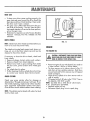
Replace the air filter every year, more often if you
mow in very dusty, dirty conditions. Do not wash air
fiher_
TO CHANGE
TURN
AIR FILTER
o Remove the air filter cover by turning counter_
clockwise to the stop and pull away from collar
(See Fig. 13).
o Remove filter from inside of cover (See Fig. 13)_
o Clean the inside of the cover and the collar to
CLOCKWESE
TO TIGHTEN
FIG. 13
remove any dirt accumutation_
_, Insert new filter into cover.
°
Put air filter cover' and filter into collar
the tab with the slot.
aligning
Push in on cover and turn clockwise to tighten (See
Fig° 13).
o
SPARKPLUG
Turn lawn mower on its side with carburetor
up,
Clean the underside of your lawn mower by
scraping to remove build-up of grass and trash.
NOTE: We recommend that you clean the underside
of your' lawn mower after each use.
Change your spark plug each year to make your
engine start easier and run better_ Set spark plug
gap at .030 inch.
Clean your' lawn mower and engine often to keep
trash from accumulating around engine. A clogged engine runs hotter and shortens engine life.
(LEANnNG
iTCANNOT
COrn COmAa
W TH
SW
PAR
CAUTION:
=SCO.NEa
SPA,K
,EJ
......................................
14
NOTE: We DO NOT recommend using a garden hose
to clean lawn mower unless the electrical system, muffler, air filter, and carburetor
are covered to keep
water out. Water in engine can result in shortening
engine life.
!iI!RVI
AI)IIISTIIIIilIT
TO IB_OVE/R[PLACEDRIVEBELT
×iL, HEX
!
SPARRPLUG.PLACE
W_IE WHEREIT CANi'JOT
COMEIN CONTACT
wife SPAIR PLUG.
H_AD
SCREW
//
i
f
=,,=ox, ==_
o Remove drive cover. Remove belt by pushing
down on gear case pulley (See Fig_ 14).
Turn lawn mower on its side with carburetor and
fuel cap up.
o Loosen hex head screw and move belt snubber
away from pulley (See Fig. 14)o
o Remove belt from engine pulley on crankshaft and
carefully slip beh off over blade_
o CAUTION: Sharp edges of blade can cut bell
Install new belt reversing above steps.
Move belt snubber back in place and tighten hex
head screw_
NOTE: Belt snubber dears belt by approx. 1/32 inch
when installed°
Always use factory approved belt to assure fit
and tong life_
)
ROTATE
PRESS I---'i_
FIG. 14
,JAM NUT
-B'"
DRIVE
POSITION
ARM
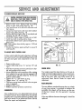
TO ADJUSTDRIVECONTROL
CABLE
A drive control cable that needs adjustment will keep
your lawn mower from self-propellng properly and
can also cause gear case components to wear out
sooner°
o Remove drive cover.
Loosen cable clamp screw "A"
llCll
FIG. 15
and nuts "B" and
_
ENGINESPEED
o Hold down operator presence control bar to handle and engage drive controt0
o Move shifter arm to drive position while rotating
front wheels to be sure jaw clutch is engaged. Pull
threaded sleeve with pliers (See Fig. 15) 0Do Not
pull on control cable.
o Tighten nut "C" until sleeve is snug.
o Tighten screw "A" and nut "B".
o Push lawn mower back and forth to be sure gear
case is engaged°
o Replace drive cover.
o Release operator presence control bar.
Your engine speed has been factory set. Do not attempt to increase engine speed or it may result in personal injury. If you believe that engine is running too
fast or too slow, take your lawn mower to an
authorized Sears Service Center for repair and
adjustment.
REARDEFLECTOR
The rear deflector, attached between the rear wheels
of your lawn mower, is provided to minimize the
possibility that objects wil be thrown out the rear
of the lawn mower into the operator's mowing
positiom
CARBURETOR
Your carburetor has a non-adjustable fixed main jet
for mixture control. If your engine does not operate
properly due to suspected carburetor problems, take
your lawn mower to an authorized Sears Service
Center for repair and adjustment.
if the rear deflector becomes damaged, it should be
replaced.
15
llilVl(l Ii
T
A IIIT
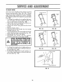
TO ADJUSTHANDLE
Your lawn mower
handle can be raised or lowered
SHIPPING
for your mowing comfort. Figs. 16A, 16B, 17A and
17B show the four (4) positions that are avaiJable:
High, medium high, medium low and low. Handles
are shipped mounted in the medium low position (See
Fig. 16A)
To change from medium low to medium high position, the upper and lower handle sections will
have to be turned over (See Fig. 16B).
o Remove the controls and operator presence control bar from the upper handle.
Remove the starter rope guide from the lower
handle.
POSIT{ON
MEDIUM
LOW
HIGH
MEDIUM
o
Remove hairpin cotters.
Disconnect the lower handle from the handle
brackets (See Fig.. 18).
Turn the handle over and reassemble the hairpin
cotters that have been removed (See Fig. 18).
o Reassemble the starter rope guide.
• Reassemble
the controls
and the operator
presence control bar to the upper handle.
FIG. 16A
FIG. 16B
HIGH
CAUTION: THEOPERATORPRESENCE
CONTROL
BAR tYIUSTPIVOT FREELYTO PERMIT BLADE
BRAREENGAGEMENTWHEN CONTROLBARIS
RELEASED. DO NOT OVERTIGHTEN THE
FASTENERS
HOLDING THE CONTROLSTO THE
UPPERHANDLE.
o To change from medium tow to
ly the upper handle section will
ed over (See Fig. 17A).
o To change from medium low to
ly the lower handle section will
ed over (See Fig. !7B).
high position onhave to be turn-
FIG. 17A
FIG. 17B
low position, onhave to be turn-
LOWER HANDLE
HAIRPIN
COTTER
HANDLE
FIG. 18
16
BRACKET
Your lawn mower and engine should be prepared
for off-season storage as follows:
LAWN MOWER
OPERATOR
CONTROL
PRESENCE
BAR
UPPER
"
Clean underside of tawn mower housing. (See
"Cleaning"
in maintenance
section of manuaL)
Inspect and replace/sharpen
blade, if required
(See
"Blade/Blade
Adapter
Care"
in
maintenance
section of manual).
., Hose grass catcher off with water and let dry
before storing.
Lubricate as shown in Service Recommendation
chart
on page
FOLD FORWARD
FOR STORAGE
MOWING
POS_TION
!8 of manual.
HANDLE
LOWER
H,
NOLE
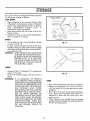
o
You can fold your lawn mower handle for storage
as shown in Fig 19.
o
To fold, squeeze the bottom ends of the lower
handle toward each other until the lower handle
clears the handle bracket, then move handle forward (See Fig. 20).
II_PORTANT: WHEN
FOLDING THE HANDLE FOR
STORAGE
OR TRANSPORTATION,
BE SURE TO FOLD THE HANDLE AS
SHOWN
IN FIG. 19. IF YOU FOLD
THE UPPER HANDLE SECTION THE
WRONG
WAY, YOU MAY DAMAGE
THE CONTROL
CABLES.
FIG. 19
&_
\
""
LOWER
"',.
HANDLE
///
"_,
HANDLE
BRACKET
\
,F.,:L.
'_'_tHAIRPIN COTTER
ENGINE
o
o
Change oil (See "To Change Oil" in maintenance
section of manual).
Drain Fuel and Run Engine until fuel system is
empty.
FIG. 20
t_POMANT: IT IS IMPORTANT
TO PREVENT
GUM DEPOSITS FROM FORMING
IN ESSENTIAL FUEL SYSTEM PARTS
SUCH AS THE CARBURETOR,
FUEL
FILTER, FUEL HOSE, OR TANK DURING
STORAGE.
ALSO,
EXPERIENCE INDICATES
THAT ALCOHOL
BLENDED
HOL OR
FUELS
USING
OTHER
o
o
Do not store gasoline from one season to another°
Replace your gasoline can if your can starts to
rust. Rust and/or dirt in your gasoline can cause
problems.
,_ Do not store your lawn mower under any plastic
cover. Plastic cannot breathe which allows con-
(CALLED GASOETHANOL
OR
METHANOL)
CAN ATTRACT MOISTURE WHICH
LEADS TO SEPARATION AND FORMATION
OF ACIDS
DURING
STORAGE°
ACIDIC
GAS
CAN DAMAGE
THE FUEL SYSTEM
OF
AN
ENGINE
WHILE
1N
STORAGE.
densation
to form
mower to rust°
and
can
cause your
lawn
o When setting up your handle from the storage
position, the lower handle will automatically
lock
into the mowing positiom
17
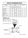
SERVICE
RECORD
SCHEDULE
Fill in dates as you complete regular
service
First
2
Hours
Every
10
Hours
SERVICE
DATES
................. _'i .............
Every
Every
25
50
Hours
Hours
Every
Use
Blades Sharpened
Blades Replaced
Engine Oil Change
_
Engine Oil Check
Air Cleaner
Spark Plug Replaced
..........
Lubricate Lawn Mower
Cleaning
Grass Catcher (if applicable)
Muffler'
....................
/,_
-
:....................................
CHECK
LLI£RI(IIION
CIAR
O
SAE 30 MOTOR
SPRAY
BRAKE
SPRING
OIL
(1OW 30)
LUBRICANT
BRACKET
ENGINE
©
HANDLE
BRACKET
MOUNTING
PIN
REAR
DOOR
OIL
HINGE
WHEEL
18
ADJUSTER
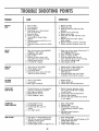
CAUSE
PROBLEM
DOESNOT
START
1,
2
3.
4,
5,
6
7.
8.
9.
CORRECTION
Dirty air filter.
Out of gasoline_
Stale gasoline,
Spark plug wire is disconnected
from the spark plug
Bad spark p?ug_
Water in gasollne_
Loose b_ade or broken blade
adapter.
Operator presence control bar in released position,
Operator presence control bar defective,
1. Replace air filter
2 Fill gasofine tank,
3, Drain gas tank and refill with fresh
gasoline,
4, Connect wire to spark plug_
5o Replace spark plug,
6o Drain tank and refill with fresh, dean
gasoline,,
7, Tighten blade bolt and/or replace
blade adapter.
8, Depress operator presence control bar
9, Replace operator presence control bar
LOSSOF
POWER
1_ Rear of lawn mower houslng/biade
dragging in heavy grass_
2, Cutting too much grass_
3, Dirty air filter
4_ Build-up of grass, leaves, and
trash under lawn mower housing,_
5_ Walking speed too fast_
6_ Too much oil in engine_
1_, Raise rear of lawn mower housing one (1)
setting higher than front°
2 Set in HIGHER CUT position,
3., Clean or replace air filter,,
4 Disconnect spark plug wire and
dean underside of fawn mower housing,
r Cut at slower walking
speed_
Check engine oil level
POORCUTUNEVEN
1
2,
3,,
4o
I, Replace blade Tighten blade bolt_
2o Set all wheels at same height_
3 Set engine speed control in
H?GH position,
4, Disconnect spark plug wire & clean
underside of lawn mower housing_
TOO_UCH
VIBRATION
1_, Worn or bent blade,,
2, Loose blade.,
3_ Bent engine crankshaft
1,, Replace blade.
2. Tighten blade boll
3, Contact Sears Service Department
STARTERROPE
HARDTO PULL
1, Flywheel brake is on when operator
presence control bar is released_
2, Bent engine crankshaft.
3 Blade adapter sheared
4_ Blade dragging in grass,
1. Depress operator presence control
bar to upper handie before pulling
on starter rope,
2 Contact Sears Service Department°
3_ Replace blade adapter.
4_ Get over low grass andtor hard surface
to start engine,
CATCHER
NOT
FILLINGCOMPLETELY
1., Cutting height too low,.
2. Lift on blade worn off°
3 Catcher bag dirty, poor air
venting
4 Low engine speed,
1,, Raise cutting height.
2r Replace blade°
3, Cteanfreplace catcher bag°
(If optional grass catcher is being
used),
4, Set engine speed control in
HIGH position_
HARDTO PUSH
1, High grass or cutting height too Iow_
2, Rear of lawn mower housing/blade
dragging in heavy grass°
3, Grass catcher too full.,
4_ Handle height position not right for you_
' .i i....,i_.
Worn, bent or loose blade,
Whee? heights uneven,
Low engine speed_
Build-up of grass, leaves and trash
under lawn mower housing
.iI ,.=
19
, Raise cutting height°
, Raise rear of lawn mower housing one (1)
setting higher than front.
3, Empty grass catcher_
4, Adjust handle height to suit,
U)
<
I
<
UJ_
0
O_
N
_J
\
/
r_
O_
LU
Z
.J
uJ
0
\
W
0
\
\
'\
Z
<
.J
>-
<
t-
0
Z
<
I--
13.
<
0
20
cO
x
x
0
_
._,
oO
_
_o
E
Z
n
0
X
O_
0
O_
_0_
_oo_
_-- 0
0'_
_- t'_ 0"_ o_
$$
o_0_0
OCOl
0o_-
_
0__
0_0_0
_00_0_
_0_0__
_0
___0_000
___0_0_
_._o
___0__
eq
r,,,
00
r,,,
t"-
0"_
_d
__0_
_Z
ILl
rn
Z
,.,J
ILl
0
_r
w
0
Z
..J
>.
3
co
E
Z
F--
0
e_
e,j
Z
p.
U.
rr
(0
rrz
_
_
0_
__
__
0
_
0
r',t'
m
w_
0
N
N
c,O
ILl
.,,,,i
8
W
0
Z
,-!
>,,
I-,
0
b.,
e,,!
z
I-
o
22
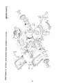
CRAFTSMAN
22"
ROTARY
LAWN
MOWER
MODEL\NUMBER
REPAgR PARTS
917.372290
Rev.
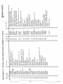
Ref.
No.
Part
No,
iii
Name
. 111111111111
ii
1
2
3
4
5
6
7
8
9
!1
12
13
14
t_
_
Part
15
16
17
18
19
21
22
23
24
25
26
27
i
iiiiiiii
u ij/llHIIIIIIIIII ii1,1
48029
74189
750029
83691
54338
55015
77400
52160
Drive Control
Drive Head Kit
Locknut
10-24
Pan Head Machine Screw
10-24
V-Belt
Hex Head Bolt 1/4-20 x 2 3/4
Retainer Clip
Hubcap
Washer
87729
53753
74507
76401
86273
86274
851020
87877
Wheel & Tire Assembly
E-Ring
Pinion
Dust Cover
Spacer Beanng
BelleViIle Washer
•
Selector
spring
(Left)
Selector
Knob
88285
61528
851022
851226
750862
87866
750097
8.00
x 2
'
Part
No.
28
29
750293
750108
30
31
32
33
34
35
83700
74976
83681
48176
STD580014
48175
48184
83632
ii
iii
x 2.00
Axle Arm Assembly
r'. _._.. _ :e_ ! ? i
.___heel
Adjustrng
Bracket
Retaining
Ctip
_71"/"
Flat Head Machine
Screw
Selector
Spring (Right)
Washer
Drive Cover Decal
Pan Head Tapping
Screw 10-24 x 2 3/4
Hex Washer Head Screw
10-24 x 3/8
":::3
ii
Ref,
No.
39
/40_
42
43
44
45
46
47
48
49
5O
5t
52
53
Part
i
1
Name
T:"""T":
D;;ve
Cover
.........................
Hex Washer Head Tapping Screw
10-24 x 3!8
Cable Ctamp
Retaining
Ring
Drive Pulley
Drive Control Cable Kit
Woodruff
Key #3
Wheel Adiuster
Assembly
(Left)
Gear Case Assembly
Locknut
1/4_20
Woodruff
Key #213
.
.......
S_r!ng
........
....................
Wheel Adiuster
Assembly
(Right)
Baffle
87682
STD54t425
Keps Locknut
1/4-20
Catcher Bottom
Kit (Incl. Rf.#42,45)
48180
700024
Pop Rivet 3/16 x t5/16
750887
Catcher Top
103227X
• Catcher Handle Top
Truss Head Screw t/4-20
x 5/8
87870
Truss Head Screw 10-24 x 5/8
87873
Truss Head Machine
t/4-20
x 3/4
88323
STD54!410
Locknut
10-24
Catcher Frame
87871
57076
75192
Clipping
Deflector
ctuded with tawn
Accessory
mower) 7t
(not m33303
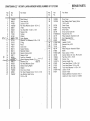
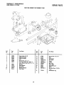
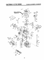
CRAFTSMAN22" POWER-PROPELLED
LAWN MOWrR 917.372290
REPAaR
GEAR CASEASSEMBLYPART NUMBER 751001
?
13
23
Eel.
Ho.
1
2
3
4
5
6
7
8
9
t0
11
Part
No.
Part Name
Refo
No.
Port
No.
Part Name
53838
85178
88386
57072
57388
48032
t(epsLocknut!/4-20
AdjustingBracket
Shifter Assembly
Seal
GroovedPin 1/8 x 1/2
Gear CaseHalves(Inc. Upper&
LowerHalves) (Incl. Ref. 4, 5, 7)
Bearing
Spring Bracket
DriveShaft
HardenedWasher
YokeClutch
12
13
14
I5
16
17
18
19
20
21
22
87822
86447
83659
750436_
750355
STD581050
850848
83720
65692
83680
STD522512
23
751046
GroovedPin I/8 x 3/4
Plug
HelicalGear
Jaw Clutch
Grease
E-Ring
Hi-Pro Key
Worm Shah
WoodruffKey #3
Worm
Hex Head Screw 1/4-20 x
1 I/4
IdentificationTag
77881
77039
750430
57079
75144
24
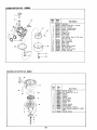
CARBURETOR NO. 632569
26
/
Ref.
Part
!
No.
No.
i
t
3
4
15
11
v
I
t
13
14
I
15
16
1
5
6
7
9
11
t2
i
I
t
631615
631616
65O5O61
631767
631971
631184
632047
631027
631021
631022
632019
631024
631700
631334
632568
631028
16
2t
22
25
I
Part Name
Carburetor
1Shaft El- Lever Assy,
Throttle
I Shutter, Throttle
Screw, Throttle shutter
ISpring0 Throttle return
!Seat, Dust
IWasher,
Flat
I Primer Assy
I Plug, Welch
I lnlet Needle,
Seat 8 Clip Ass¥
(lncl No, t3}
I Clip, Inlet needle
I FIoat, Carburetor
i Shaft, Float
Bowl,
Float
Gasket,
Bowl-to-body
Nut, Float Bowl
Gasket, Bowl-to-body
_ 632527
Fitting,
Fuel inlet
1
REWIND
STARTER
llti _1
I
'12
3,/'
I
t
k
f
_2_
I
i
I"
NO. 590621
i_-1 _3
I
i
° tT:_
- j,'J
it "__!]r
- "
31 t .... [-_/L............
( O
i
J- ........
,o
_--
i
No,,
i
1
2
3
4
5
6
7
8
9
10
11
12
_ ....... 9
6 .........u_-'_
Ref. i Part
13
7" 4 6
2
25
No.
590621
590599A
590600
590615
59O6O1
59O598
590616
590617
5906!8
590619
59O62O
59O622
59O535
59O452
Part Name
Starter, Rewind
Pin, Spring (Incl. No, 4)
Washer
Retainer
Washer
Spring, Brake
Dog, Starter
Spring, Dog
Pulley
Spring, Rewind
Cover, Spring
Housing Assy,
Starter
Rope, Starter (Length 9B" _ 9/64"
dia,)
Handle, Starter
I
i_+"292
1-93
_"292
135
r
i
130
_
101
t
119
45A
26
46
C FTS AN 4=CYCLE
ENGmNE
NO,
I
Part
No.
35010
26727
33734
342!4A
"33735
302OO
32
4O
34695
33886
28277
30589
31383A
31335
650548
31361
3260O
35801
32323
35544
40
35545
14
15 !
16
17
18
19
'
20
30
35546
4t
4t
35541
35542
41
35543
7O
35547
35548
35549
20381
32875
326t0A
27241
33148A
29914
"35261
35810
72
73
30572
"28833
42
1
43
1
80
81
83
84
86
89
9O
92
93
100
101
103
1
I
1
1
!
27897
30574
35479
30591
30588A
29193
65O488
611004
611112
650815
650816
34443A
610118
650814
t10
119
120
t25
125
34961
"33015A
34342
29313C
293t 5C
126
126
29314B
29315C
130
6021A
MODEL
No.
Part
No.
135
35395
150
!51
169
172
t74
t78
182
!84
185
186
189
31672
31673
"27234A
32755
650128
29752
620t
"26756
31384A
32653
650839
t90
191
192
193
194
t95
207
216
223
224
238A
34968
35O4O
34966
34965
32309
610973
34336
33O86
650451
"34690A
650932
239
24tA
245A
250A
260
261
*34338
35797
35O66
35065
35478
30200
262
6508.31
275B
277
285
287
290
282
300B
301
305
306
307
309
27t8tB
650795
35000
650884
34357
26460
35586
35355
35557
34265
35499
650562
3t0
3t3
327
357
370
380
390
4O0
35578
34O8O
35392
34985
35391
632569
590621
332380
Refo
PartName
Cylinder Assy, (Incl Nos, 2 8r 20)
Pin, Dowel
Element, Breather
Breather Assy (tncl Nos, 6, 8, 9, 12A
_t 12B)
Gasket, Breather
Screw, Hex washer hd, serf-tap Seres,
10-24 x 9/t6
Elbow, Breather tube
Tube, Breather
Washer,
Flat
Rod, Governor (Inel No. 14)
Lever, Governor
Clamp, Governor lever
Screw, Hex washer hd, 8-32 x 5/16
Spring, Extension
Seal, Oil
Crankshaft Assy,
Washer, Thrust
Piston,
Pin 8
Ring
Assy
(Std)
(Incl, Nos 41, 42 8 43)
Piston, Pin 8 Ring Assy
(,0!0 oversize) (Inc} Nos. 41, 42 Et 43)
Piston, Pin 8- Ring Assy. (020 oversize) (lncL Nos, 41, 42 8- 43)
Piston 8 Pin Assy (Std,) (lncl. No, 43)
Piston
8- Pin Assy.
(.010 oversize)
(tncl. Nor 431
Piston
8; Pin Assy
(,020 oversize)
(Incl- No. 43)
Ring Set, Piston (Std.)
Ring Set, Piston (010 oversize)
Ring Set, Piston (020 oversize)
Ring, Piston pin retaining
Rod Assy., Connecting
(Inct No 46)
Bolt, Connecting
rod
Vatve, Lifter
Camshaft (Compression
Refease)
Pump Assy., Oil
Gasket, Mounting
flange
Flange, Mounting
(lnct. Nos, 72, 73, 75
8- 80)
Plug, Oil drain (Incl. No 73)
Gasket,
Oil plug (Not required with
plastic oil plug)
Seal, Oil
Shaft, Governor
Washer, Flat
Gear Assy., Governor (lncl No 81)
Spool, Governor
Ring, Retaining
Screw, Hex hd Sems, 1/4-20 x 1-t/4
Key, Ffywheel
Flywheel
Washer, Belleville
Nut, Flywheel
Solid State Assy
Cover, Spark plug
Screw,
Torx hex washer hd Sems,
10-24 x 1
Wire, Ground
Gasket, Cylinder head
Head, Cylinder
NUMBER:
143.404162
Part Name
Spark Plug, Resistor (Champion
RJ19LM or equivalent)
Spring, Valve
Cap, Lower valve spring
Gasket, Valve spring box
Cover, Valve spring box
Screw, Hex hd Sems, t0-24 x 1/2
Nut Et Lockwasher,
1/4-28
Screw, Hex hd, 1/4-28 x 7/8
Gasket, Carburetor
Pipe, Intake (Incl No, 224)
Link, Governor
spring
Screw,
Hex washer
hd
Powedok,
1/4-20 x 3/8
Lever, Brake
Bracket, S E Brake
Link, Control
Spring, Extension
Ring, Retaining
Terminal Assy
Link, Throttle
Lever, Speed adjusting
Screw, Hex hd Sems, t/4-20 x !
Gasket, Intake pipe
Screw,
Hex washer
hd.. shoulder.
t0-32 x 49/64
Gasket, Air cleaner
Collar, Air cleaner
Filter, Air cleaner (Paper)
Cover, Air c}eaner
Housing, Blower
Screw, Hex washer hd self-tap Sems,
!0-24 x 9/t6
Screw,
Hex washer
hd
Powedok
thread, !/4-20 x t/2
Muffler (tnc!, No 277)
Screw, Hex hd , !/4-20 x 2-1/4
Hub, Starter
Screw, Hex washer hd , 8-32 x 1/2
Line, Fuel
Clamp, Fuel line
Tank Assy (Incl Nos 292 Ef 301)
Cap, Fuel
Tube, Oil fit!
Gasket, Fill tube
"O" Ring
Screw,
Hex washer hd shakeproof,
10-32 x 1/2
Dipstick,
Oil fill
Spacer, Flywheel key
Ptug, Starter
Retainer, Starter rope
Decal, Instruction
Carburetor
(lncl No, 184)
Starter, Rewind
Gasket Set (lncl items marked *)
RPM Settings:
High Speed: 3000
Valve, Exhaust (Std°) (Incl, Noo t51)
Valve, Exhaust {1/32" oversize) (incl,,
No. 151)
Valve, Intake (Std,) (inct, No,. 151)
Valve,
Intake
(1/32"
oversize)
(Incl, No, 151)
Screw, Hex flange hd., 5/16-18 x 1-1/2
*Indicates Parts tnctuded in
Gasket Set, Ref, No, 400
27
®
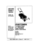
MODELNO.
917.372290
4.0 HORSEPOWER
22"' REARBAGGER
POWERPROPELLED
ROTARYLAWNMOWER
Each Lawn Mower has its own model
engine has its own model number.
number_ Each
The model number for your lawn mower will be found on
a decal attached to the rear' of the lawn mower housing
The model number for the engine will be found on the
Blower' Housing of the engine adjacent to the spark plug.
All parts listed herein may be ordered through Sears,
Roebuck and Co_ Service Center's and most Retail Stores
WHENORDERING
REPAIRPARTS,ALWAYSGIVETHEFOLLOWING
INFORMATION:
* PRODUCT- "ROTARY LAWNMOWER"
HOWTOORDER
REPAIRPARTS
* MODELNUMBER- 917_372290
* ENGINE- CRAFTSMAN
MODELNO. 143.404162
* PARTNUMBER
* PARTDESCRIPTION
Your Sears merchandise has added value when you consider that Sears has service units nationwide staffed with
Sears trained
technicians..professional
technicians
specifically trained on Sears products, having the parts,
tools and the equipment to insure that we meet our pledge
to you, we service what we selk