1
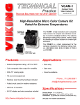
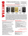
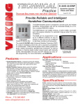
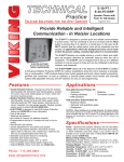
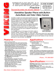
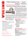
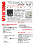
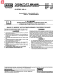
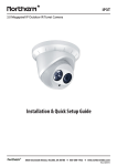
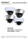
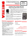
TECHNICAL
Practice
VCAM-1/1IR
VCAM-2
Compact Color
Video Camera Kit
Practice
TELECOM SOLUTIONS
FOR THE
2 1 S T C E N T U RY
August 2, 2011
Compact Color Camera Kits and
Single Gang Mountable Cameras
The VCAM-1 and VCAM-1IR are high resolution color composite video cameras. Their compact
size will allow mounting in even the smallest locations. The extreme temperature rating of this camera, makes it ideal for mounting in outdoor locations in a water tight enclosure.
Model VCAM-1
and VCAM-1IR
The VCAM-2 is a compact, high resolution color composite video camera mounted behind a standard single gang wall plate. The VCAM-2 is available in two finishes: Brushed Stainless Steel
(VCAM-2-SS) and Oil Rubbed Bronze (VCAM-2-BN). The extreme temperature rating and
Enhanced Weather Protection make this camera ideal for mounting
in outdoor locations.
The VCAM-1 is not compatible with IR illuminators and is a direct
replacement for the cameras included in the following Viking models: AES-2005, E-35, E-50,
E-65, E-75, K-1205, K-1705-3 and W-3005.
The VCAM-1IR has a day/night OLP (optical low pass) filter and is compatible with standard
840-850nM IR illuminators. The VCAM-1IR is the same size as the VCAM-1 allowing it to be
used in all of the above Viking products.
All cameras are equipped with Enhanced Weather Protection (EWP) for outdoor installations
where the unit is exposed to precipitation or condensation. The VCAM-1, VCAM-1IR and
VCAM-2 feature sealed connections, as well as an epoxy potted circuit board.
Features
VCAM-1 / VCAM-1-IR / VCAM-2 Features:
• High resolution color composite video camera with wide 70° viewing
angle, tilt/swivel adjustments, and wide operating temperature range
• Designed for outdoor use, all cameras come standard with Enhanced
Weather Protection (EWP), see DOD# 859 for more information
• All cameras designed to meet IP66 Ingress Protection Rating
• 5V DC adapter and wire connectors included
• VCAM-1-IR only: IR illuminator compatible
VCAM-2 Features:
• Compact size: Front panel is the size of a typical single gang midsize
wall plate
• Mounting: Flush mount in a single gang electrical box (2.25” deep x
2.00” wide x 2.84” tall min) electrical box or surface mount in a Viking
model VE-3x5 (not included, see DOD# 424)
• Available in 2 standard faceplate finishes: Brushed Stainless Steel
and Oil Rubbed Bronze
• PNL-VCAM-2 faceplates: Replacement faceplates with matching
screws available in both finishes
• Vandal Resistant Features: 18 gauge 304 stainless steel faceplate,
stainless steel camera mounting plate, scratch resistant powder
coating, impact and scratch resistant camera lens, and hex drive
mounting screws
• Weather Resistant Features: Faceplate gasket, sealed camera lens,
potted camera circuit board, stainless steel camera mounting hardware
• VCAM-2-BN only: UV stable weather resistant powder coating
Model VCAM-2
Applications
• Door entry
• Gate entry
• Covert surveillance
Phone...715.386.8861
[email protected]
h t t p : / / w w w. v i k i n g e l e c t r o n i c s . c o m
Specifications
Shipping Weight: VCAM-1 / VCAM-1-IR: 0.23 kg (0.5 lbs)
VCAM-2: 0.36 kg (0.8 lbs)
Operating Temperature: -40°C to 85°C (-40°F to 185°F)
Connections: (3) gel-filled butt connectors (3M Scotchlok UR2)
(See page 2 for complete specifications)
IF YOU HAVE A PROBLEM WITH A VIKING PRODUCT, PLEASE CONTACT: VIKING TECHNICAL SUPPORT AT (715) 386-8666
Our Technical Support Department is available for assistance Monday 8am - 4pm and Tuesday through Friday 8am - 5pm central time. So that we can give you better service, before you call please:
1. Know the model number, the serial number and what software version you have (see serial label).
2. Have your Technical Practice in front of you.
3. It is best if you are on site.
RETURNING PRODUCT FOR REPAIR
RETURNING PRODUCT FOR EXCHANGE
The following procedure is for equipment that needs repair:
1. Customer must contact Viking's Technical Support Department at 715-386-8666 to obtain a Return Authorization (RA)
number. The customer MUST have a complete description of the problem, with all pertinent information regarding the
defect, such as options set, conditions, symptoms, methods to duplicate problem, frequency of failure, etc.
2. Packing: Return equipment in original box or in proper packing so that damage will not occur while in transit. Static
sensitive equipment such as a circuit board should be in an anti-static bag, sandwiched between foam and individually boxed. All equipment should be wrapped to avoid packing material lodging in or sticking to the equipment. Include
ALL parts of the equipment. C.O.D. or freight collect shipments cannot be accepted. Ship cartons prepaid to:
Viking Electronics, 1531 Industrial Street, Hudson, WI 54016
3. Return shipping address: Be sure to include your return shipping address inside the box. We cannot ship to a PO Box.
4. RA number on carton: In large printing, write the R.A. number on the outside of each carton being returned.
The following procedure is for equipment that has failed out-of-box (within 10 days of purchase):
1. Customer must contact Viking’s Technical Support at 715-386-8666 to determine possible causes for the problem. The
customer MUST be able to step through recommended tests for diagnosis.
2. If the Technical Support Product Specialist determines that the equipment is defective based on the customer's input
and troubleshooting, a Return Authorization (R.A.) number will be issued. This number is valid for fourteen (14)
calendar days from the date of issue.
3. After obtaining the R.A. number, return the approved equipment to your distributor, referencing the R.A. number. Your
distributor will then replace the product over the counter at no charge. The distributor will then return the product to
Viking using the same R.A. number.
4. The distributor will NOT exchange this product without first obtaining the R.A. number from you. If you haven't
followed the steps listed in 1, 2 and 3, be aware that you will have to pay a restocking charge.
LIMITED WARRANTY
Viking warrants its products to be free from defects in the workmanship or materials, under normal use and service, for a period of one year from the date of purchase from any authorized Viking distributor
or 18 months from the date manufactured, which ever is greater. If at any time during the warranty period, the product is deemed defective or malfunctions, return the product to Viking Electronics, Inc., 1531
Industrial Street, Hudson, WI., 54016. Customer must contact Viking's Technical Support Department at 715-386-8666 to obtain a Return Authorization (R.A.) number.
This warranty does not cover any damage to the product due to lightning, over voltage, under voltage, accident, misuse, abuse, negligence or any damage caused by use of the product by the purchaser or
others.
NO OTHER WARRANTIES. VIKING MAKES NO WARRANTIES RELATING TO ITS PRODUCTS OTHER THAN AS DESCRIBED ABOVE AND DISCLAIMS ANY EXPRESS OR IMPLIED WARRANTIES OR
MERCHANTABILITY OR FITNESS FOR ANY PARTICULAR PURPOSE.
EXCLUSION OF CONSEQUENTIAL DAMAGES. VIKING SHALL NOT, UNDER ANY CIRCUMSTANCES, BE LIABLE TO PURCHASER, OR ANY OTHER PARTY, FOR CONSEQUENTIAL, INCIDENTAL,
SPECIAL OR EXEMPLARY DAMAGES ARISING OUT OF OR RELATED TO THE SALE OR USE OF THE PRODUCT SOLD HEREUNDER.
EXCLUSIVE REMEDY AND LIMITATION OF LIABILITY. WHETHER IN AN ACTION BASED ON CONTRACT, TORT (INCLUDING NEGLIGENCE OR STRICT LIABILITY) OR ANY OTHER LEGAL THEORY, ANY LIABILITY OF VIKING SHALL BE LIMITED TO REPAIR OR REPLACEMENT OF THE PRODUCT, OR AT VIKING'S OPTION, REFUND OF THE PURCHASE PRICE AS THE EXCLUSIVE REMEDY
AND ANY LIABILITY OF VIKING SHALL BE SO LIMITED.
IT IS EXPRESSLY UNDERSTOOD AND AGREED THAT EACH AND EVERY PROVISION OF THIS AGREEMENT WHICH PROVIDES FOR DISCLAIMER OF WARRANTIES, EXCLUSION OF CONSEQUENTIAL DAMAGES, AND EXCLUSIVE REMEDY AND LIMITATION OF LIABILITY, ARE SEVERABLE FROM ANY OTHER PROVISION AND EACH PROVISION IS A SEPARABLE AND INDEPENDENT
ELEMENT OF RISK ALLOCATION AND IS INTENDED TO BE ENFORCED AS SUCH.
PART 15 LIMITATIONS
This equipment has been tested and found to comply with the limits for a Class A digital device, pursuant to Part 15 of the FCC Rules. These limits are designed to provide reasonable protection against harmful
interference when the equipment is operated in a commercial environment. This equipment generates, uses, and can radiate radio frequency energy and, if not installed and used in accordance with the instruction
manual, may cause harmful interference to radio communications. Operation of this equipment in a residential area is likely to cause harmful interference in which case the user will be required to correct the interference at his own expense.
Specifications
Electrical
Image Sensor: 1/4” color CMOS
Active Pixels: 640 x 480 @ 30 fps
Resolution: 420TVL
Sensitivity: 0.26 lux (20 IRE) F 2.0
Lens: 3.4mm pinhole, semi-conical
FOV (Field of View): 70°
Signal to Noise Ratio: 46 dB
Gamma: 0.45
Gain: Automatic 36 dB
Synchronization: Internal
Back Light Compensation: Off
White Balance: AWB
Shutter Mode: Electronic rolling shutter
Shutter Speed: Auto exposure or fixed
Frame Rate: 30 fps
Scan Mode: Interlaced
Contour Enhancement: Enabled
Dynamic Range: 73.4 dB
Iris Controls: Electronic (no DC signal)
Video Output: 1V p-p composite, NTSC, 75 Ohms
Power Input: 3.5-6V DC regulated (polarity protected) 5V DC
regulated adapter included
Power Consumption: < 150mA
Connector: 6 pin JST SHR-06V-S-B
Wire: 7” flying leads, 24 AWG stranded, yellow = video out,
red = +6VDC, black = -/GND
2
Maximum Wire Run Length: 750 ft with RG59/RG6 for video
and CAT5 for power (3 pairs) and entry phone audio (1 pair). 150
ft with CAT5E for video, power and entry phone audio (longer
video runs are possible by using video balun tranceivers, see
Installation section).
Environmental
Operating Temperature: -40°C / -40°F ~ 85° / 185°F
Storage Temperature: -40°C / -40°F ~ 90° / 194°F
Operating Humidity: 5% - 95% non-condensing
Mechanical
Dimensions WxHxD: 26mm x 24mm x 19mm (1.03” x 0.94” x
0.76”)
Weight: 13.4g (0.036 lbs)
VCAM-1/VCAM-2 IR Compatibility: This camera is equipped with
an OLP (Optical Low Pass) filter to maintain correct video color in
outside applications. The standard camera is not compatible with
IR illuminators. If IR illumination is required, see Viking model
VCAM-1IR.
VCAM-1IR: This camera is equipped with a Day/Night OLP
(Optical Low Pass) filter and is compatible with standard 840850nM IR illuminators. All other specifications are identical to the
VCAM-1/VCAM-2.
Installation
A. Surface Mounting the VCAM-2
A Viking model VE-3x5 can be used to surface mount a VCAM-2 to a wall or post. Recommended mounting height to
bottom of VE-3x5 is 50” - 54”. Drill a small wire exit hole in wall. Pull wire through and seal hole around wire with putty
or caulking. Route wire into the VE-3x5 box, securely screw it to wall or post and seal hole in box around wire with
putty or caulking. Note: Conduit may also be used when surface mounting wire, but should not enter through the top
of the VE-3x5. When routing wiring from above, a drip loop is required. WARNING: Do NOT use a typical “wet location box” as not all styles seal properly with the VCAM-2 faceplate.
B. Mounting the VCAM-2 Faceplate
After the Rough-In box or VE-3x5 is securely mounted, caulking between the box and rough opening is completed (if
required), wires are connected, and camera is tilted and rotated to the desired position (as shown in section G). Remove
paper liner from face plate gasket and press gasket to the back of the faceplate. Push the 1-1/4" 6-32 screws through faceplate holes and small holes in gasket, the faceplate gasket should retain the screws. Position the camera mounting plate over
screws. Align screws with single gang box bosses and tighten face plate until gasket is fully collapsed. Included 1/4" thick
gasket will provide an adequate seal for most siding surfaces; however for rough surfaces (ie: brick, stucco, etc.) additional
caulking may be required.
3.17"
Optional Wing
Brackets
1.8"
3.125"
(3) 3-Wire Gel-Filled
Butt Connectors
(included)
Optional
Mounting Ears
2.00"
Wide
Min.
4.92"
*2.25"
Deep
Min.
-OR-
Wires from
Camera
2.84"
Tall Min.
W/O
G/W
W/G
Condensation
Drain Hole
Conduit Knockout
Optional VE-3x5 Surface Mount
Box with Black Satin Powder Paint
Finish (not included) WARNING: Do
NOT use a wet location box.
4.875"
O/W
CAT5E
Cable
"Old Work" Rough-In Box
(Allied Molded 9331 box
shown, not included)
Red
Black
Yellow
(4) Optional Dry
Wall Screws
(not included)
Camera
Mounting Plate
(included)
1/4" Thick Foam
Faceplate Gasket
(included)
Facplate
(included)
(2) 6-32 x 1.25" Long
5/64" Hexdrive Flathead
Screws (included)
C. Mounting the VCAM-1
IMPORTANT: Electronic devices are susceptible to lightning
and power station electrical surges from both the AC outlet and
the telephone line. It is recommended that a surge protector
be installed to protect against such surges.
!
Note: The recommended camera mounting height is
50.0” - 56.0” from the ground.
Example:
Side View of
Model E-50
(not included)
#2 Lock Washer (included)
#2-56 x 3/16 Phillips Screw (included)
3
D. Wiring
1. Using RG59 for Video and CAT5 for Camera Power (Recommended)
Example:
Back View of the VCAM-2
DEV:
P/N: 26703A
Viking Electronics, Inc. (715) 386-8861
1531 Industrial St., Hudson, WI 54016
Model: VCAM-2
REN 0.8A: Serial No: XXXXXXXX
Complies with FCC Part 15 and 68 Reg. No: US:AH3TE08A22264
3-Wire Gel-Filled Butt Connectors
included (3M Scotchlok UR2)
Yellow (Video)
*** RG59 or RG6
Shielded
Video Cable
Center conductor
stripped back 5/8"
"F" to Phono Plug
Adapter (Radio
"F"
Connector
Shack part #278-252)
Up to 750 ft
Twisted foil and
braided shield
To unused input on TV,
VHF modulator, whole
house video distribution
equipment, IP video
encoder (Axis M7001), etc.
5V DC Adapter
(included)
- Black (GND)
!
VIKING
Black
CAT5 Cable
** Camera GND (-)
W/O
W/O
O/W
+ Red (6VDC)
** Camera Pwr (+)
O/W
Camera GND (-)
(-)
120V AC
(+)
Black with
White Stripe
Camera Power (+)
Crimp-on Splice
Connectors (not included)
** Up to 250 ft
2. Using CAT5E or CAT6 for Video and Camera Power (see Caution below)
Example:
To unused input on TV, VHF
modulator, whole house video
distribution equipment, IP video
encoder (Axis M7001), etc.
DEV:
P/N: 26703A
Viking Electronics, Inc. (715) 386-8861
1531 Industrial St., Hudson, WI 54016
Model: VCAM-2
REN 0.8A: Serial No: XXXXXXXX
Complies with FCC Part 15 and 68 Reg. No: US:AH3TE08A22264
Back View of the VCAM-2
(+)
Video GND (-)
W/G
Video Out (+)
VIKING
Video GND (-)
(-)
Video Out (+)
3-Wire Gel-Filled Butt
Connectors included
(3M Scotchlok UR2)
G/W
5V DC Adapter
(included)
CAT5E or
CAT6 Cable
W/G
Phono (RCA) Plug,
F Connector, Etc.
G/W
W/O
** Camera GND (-)
W/O
** Camera Pwr (+)
O/W
!
Black
(see Caution below)
O/W
Camera GND (-)
Camera Power (+)
* Up to 150 ft
(-)
120V AC
(+)
Black with
White Stripe
(4) Crimp-on Splice
Connectors (not included)
* Note: Up to 150 ft video cable run length can be achieved using CAT5E or CAT6 cable. Longer cable runs can be used if a passive or active video Balun transceiver is used on
each end of the cable. Generally, passive transceivers can achieve up to 750 ft cable runs where active transceivers can achieve up to 3000 ft runs depending on cable type, etc.
The type of video balun transceiver required is specific to your cable run length. For more information on video balun transceivers go to: www.northernvideo.com.
** Note: The maximum camera power supply wire run length is 250 ft of 24 gauge wire (CAT 5/6), longer runs are possible by doubling pairs or increasing the wire gauge.
*** Note: RG59 or RG6 with solid center conductor and 95% bare copper braid shield.
Caution: When routing CAT5E or CAT6 cable, maintain a minimum distance of 3 ft from any parallel high voltage wire (110 VAC) and a minimum of 2 ft from crossing any high voltage wire. For installations where RF noise is expected (commercial applications) or wire runs are near high voltage (110 VAC) wires, a shielded video cable such as RG6 is recommended.
E. Adjusting the Camera
Horizontal (Rotation)
Adjustment
+/- 30 degrees maximum
The camera can be tilted and rotated to your desired position. A portable
service (test) monitor can be used to determine the correct viewing
angle during installation.
Important: To prevent the edge of the faceplate from being viewed in
the video image, do not rotate the camera beyond 30 degrees or tilt
beyond 20 degrees.
Product Support Line...715.386.8666
Vertical (Tilt)
Adjustment
+/- 20 degrees
maximum
Fax Back Line...715.386.4345
Due to the dynamic nature of the product design, the information contained in this document is subject to change without notice. Viking Electronics, and its affiliates and/or subsidiaries
assume no responsibility for errors and omissions contained in this information. Revisions of this document or new editions of it may be issued to incorporate such changes.
4
DOD# 190
Printed in the U.S.A.
ZF302660 Rev D