1
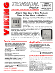
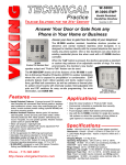
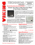
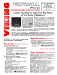
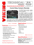
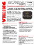
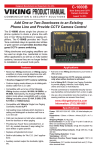
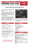
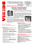
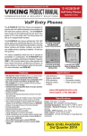
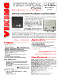
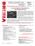
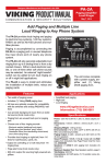
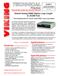
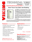
Designed, Manufactured and Supported in the USA
VIKING PRODUCT MANUAL
C O M M U N I C AT I O N & S E C U R I T Y S O L U T I O N S
W-Series
Vandal Resistant
Handsfree Doorboxes
January 16, 2014
Answer Your Door or Gate from the Safety of
Any Phone in Your Home or Business
The W-Series handsfree doorboxes are available in
three different chassis configurations. The W-1000
has an aluminum faceplate with black textured powder
paint and call progress LED. The W-2000A provides
a surface mount light grey UV stable plastic chassis.
The W-3000 provides an attractive vandal resistant
stainless steel faceplate and call progress LED. The
W-Series are designed to interface directly with an unused analog telephone line input of phone system.
One or two doorboxes can also share an existing
phone line when used with a C-1000B doorbox controller.
W-1000/
W-1000-EWP
Flush Mount
Black Powder
Painted Aluminum
W-2000A/
W-2000A-EWP
Surface Mount Light
Grey UV Stable
Plastic Chassis
W-3000/
W-3000-EWP
Flush Mount
Brushed 316
Stainless Steel
The EWP versions share all of the features of the
standard W-Series in addition to Enhanced Weather
Protection (EWP) for outdoor installations where the
unit is exposed to precipitation or condensation. EWP
products feature foam rubber gaskets and boots,
sealed connections, gel-filled butt connectors, as well
as urethane or thermal plastic potted circuit boards
with internally sealed, field-adjustable trim pots and
DIP switches for easy on-site programming. For more
information, see DOD# 859.
Features
Applications
When the “Call“ button is pressed, the doorbox generates a standard or custom ring cadence of an adjustable number of rings. For noisy environments, the
doorbox’s new louder speaker output and “Push-toTalk” feature can be used.
• W-1000 Faceplate: Vandal resistant 12 gauge louvered aluminum with weather resistant black textured
powder paint and UV stable white silk screened
graphics.
• W-2000A Chassis: Impact resistant, UV stable, light
grey Geloy plastic with black UV stable pad printed
graphics. Surface mount only.
• W-3000 Faceplate: Vandal resistant 14 gauge louvered 316 marine grade stainless steel with #4
brushed finish and permanent laser etched graphics.
• Connect to a phone system’s unused trunk input, FXO
port or a Viking C-1000B Controller
• Weather Resistant Features: Marine grade 316
stainless steel screws and push button switch (W1000/W-3000). Switch internally sealed per IP67.
Mylar speaker. Self-draining mic mount. Faceplate,
mic and speaker gaskets.
• Blue call progress / night light LED (W-1000/W-3000)
• High output speaker amplifier with volume adjustment
• Microphone volume adjustment POT
• 24 volt talk battery
• 20 Hz ring generator (6.0 REN ring load maximum)
• Selectable ring cadence (standard, double,
short/short/long, or short/long/short)
• Selectable number of rings (2, 3, 10 or 30)
• Selectable “Push-to-Talk” feature for noisy environments
• Operating temperature range: -15°F to 130°F
• EWP versions are designed to meet IP66 Ingress Protection Rating (see DOD# 859 for more information)
•
•
•
•
•
Ideal for noisy locations in “Push-to-Talk” mode
Commercial, industrial or residential door security
Door or gate communication
Truck stop/gas station fuel island communication
Use with the C-1000B controller for single line residential systems or when the operation of door strikes
or gate openers is necessary (see DOD# 155)
www.vikingelectronics.com
Information: (715) 386-8861
Specifications
Power: 120V AC/13.8V AC 1.25A UL listed adapter provided
W-1000/W-3000 Dimensions: Overall - 127mm x 127mm x
57.2mm (5.0” x 5.0” x 2.25”) Plastic Rough-In Box - 102mm x
102mm x 54mm (4.0” x 4.0” x 2.12”)
W-2000A Dimensions: 140mm x 115mm x 40mm (5.5” x 4.5”
x 1.6”)
Shipping Weight: 1.81 Kg (4 lbs)
Operating Temperature: -26°C to 54°C (-15°F to 130°F)
Humidity - Standard Products: 5% to 95% non-condensing
Humidity - EWP Products: Up to 100%
Ringer Output: 20 Hz, 6.0 REN load maximum
Maximum Line Loop Length with 24 AWG Twisted Pair:
1.9 Km (6300 ft)
Maximum Power Run Length with CAT5 Wire: 1 pair =
150ft, 2 pair = 300ft, 3 pair = 450ft Note: Power run length
may be increased, see Wiring section
Connections: (4) gel filled butt connectors
Installation
IMPORTANT: Electronic devices are susceptible to lightning and power station electrical surges from both the AC
outlet and the telephone line. It is recommended that a surge protector be installed to protect against such surges.
A. Mounting the W-1000 and W-3000
Caution: When warm air comes in contact with cold surfaces, such as outside walls, it causes condensation. To
help prevent condensation from accumulating inside the W-1000/3000, bring conduit into the bottom of the unit.
If this is not possible, drill a 1/4” diameter hole in the bottom of the plastic rough-in box.
2.1”
Front View of Plastic
Rough-In Box (included)
* 1/8" thick foam gasket (included)
4.0"
Wall Stud
* Note: Peel off paper liner and
adhere gasket to the back of the
faceplate, centering it over the
four corner mounting holes.
5.0” Typical
Call
(2) Standard flat head dry wall
(sheet rock) screws (not included)
Marine grade 316 stainless steel
push button switch (sealed per IP67)
Important: The W-1000/3000 will NOT mount to a
standard double gang box.
Push to Call Button
Blue Call Progress/Nightlight LED
Note: The plastic rough-in box (part # 259576)
may be purchased separately in advance. Go to
www.vikingelectronics.com and click on “spare parts”.
5.22”
W-3000-EWP
shown with
optional
Viking Model
VE-5X5 Surface
Mount Box
and
VE-GNP
Gooseneck
Pedestal
Marine grade 316 stainless
steel faceplate (W-3000 only)
Wire knock out
(4) 6-32 X 3/4” Marine grade 316 stainless steel,
flat head, 5/64" hexdrive screws (included)
Condensation Drain Hole
3.25”
(4) 0.38” diameter (for gooseneck mounting)
(4) 0.2 x 0.43 slots for double gang box
(2) 0.2 x 0.43 slots for single gang box
5.14”
(1) .74" dia
3.0” 3.3”
Condensation
Drain Hole
3.0”
2.25”
Front View of Optional
VE-5x5 (not included)
The optional VE-5x5 Surface Mount Box is
designed to be surface mounted to a single gang
box, double gang box or VE-GNP gooseneck
pedestal (right). For more information on the
VE-5x5 and VE-GNP see DOD# 424.
Rear View of VE-5x5 (not included)
3.40”
1.55”
B. Mounting the W-2000A
The W-2000A and W-2000A-EWP are designed to be surface
mounted to a single gang box (not included), a standard 4” x 4”
electrical junction box (not included), or directly to a wall or flat
sided post.
Note: For outdoor applications apply
a bead of caulk between back panel
and wall.
Front View of the
W-2000A / W-2000A-EWP
3.40”
2.35”
3.30”
Rear View of the
W-2000A / W-200A-EWP
Mounting Specifications
Internal View of the back panel
W-2000A / W-2000A-EWP
Side View of the
W-2000A / W-2000A-EWP
UP
Call
VIKING©
2
To open the speaker
box, remove the two
screws from the cover.
Mount the back panel to a
wall, a single gang box or
a 4” x 4” junction box with
the arrow pointing up.
Attach the cover to the
base with the two included
screws as shown.
C. Wiring
Rear View of W-1000 / W-3000
Rear View of W-2000A
3.63" Typical
(Spade
connector
included)
(Spade
connector
included)
Wire as
shown
below
3.63"
** Earth
Ground
(optional)
CAUTION:
Do NOT install a
W-1000,W-2000A
or W-3000 on a
telephone line
without a C-1000B
Controller
(see DOD# 155).
** Earth
Ground
(optional)
ON
3
3
2
1
2
1
ON
ON
2
1
ON
1
2
C-1000B Controller
VIKING ©
MODEL C-1000B
VIKING
1
2
3
6 7 8
* Gel-Filled Butt
Connectors
Red/Black
EARTH C.O. LINE
GND
INPUT
OUT TO
PHONES
KEYLESS
C.C. INPUT
DOOR
STRIKE 1
DOOR
STRIKE 2
N.C.
COM
DOORBOX 2
TALK
OFF
DOOR
BOX 1
DOORBOX
13VAC PWR
BATTERY
ON
DOOR
BOX 2
1 2 3
C
LED2
N.O. COM N.C.
DOOR STRIKE 1
C
LED3
N.O. COM N.C.
DOOR STRIKE 2
To 2nd
Doorbox
Green (Tip)
OR
Black/Red
N.C.
ON
C
LED1
*** 13.8VAC
(18VAC max)
COM
9 10 11 12 13 14 15 16 17 18 19
N.O. N.C. - - - - AUX.
CONTACT
OUTPUT
SIG GND SIG GND SIG GND
VIDEO 1 IN VIDEO 2 IN VIDEO OUT
120V AC
N.O.
DOORBOX
PWR OUTPUT
DOORBOX 1
KEYLESS CONTACT
CLOSURE INPUT
LINE OUT
TO PHONES
4 5
COM
N.O.
Wires from
W-1000 / W-2000A / W-3000
PHONE LINE
INPUT
Single Line
Phone
DOOR ENTRY / CCTV VIDEO
CONTROLLER
EARTH
GND
Wire as
shown below
POWER 13.8V AC
ELECTRONICS
HUDSON, WI 54016
Unused
PABX/KSU
Trunk Input
Red (Ring)
* Note: The gel-filled (water-tight) butt connectors are designed for insulation displacement on 19-26 guage wire
with a maximum insulation of 0.082 inches. Cut off
stripped wire ends prior to terminating.
Multi-Line
Phone
C.O.
Line
** Note: To increase surge protection, loosen the PCB mounting screw labeled
(as shown above) and fasten
a wire with spade terminal (included) from the mounting screw to Earth Ground (grounding rod, water pipe, etc.)
*** Warning: The power run wire length is limited to 150 ft of CAT5 wire. Longer power runs will require heavier
gauge wire (doubling or tripling pairs) and/or a higher voltage power adapter. Voltage at the doorbox power input
connections must not exceed 18VAC RMS.
Programming
A. DIP Switches
S1 DIP Switches
ON
1
2
3
OFF
S2 DIP Switches
ON
1
ON
2
Switch 1 Switch 2 Ring Output
OFF
OFF
2 rings
ON
OFF
3 rings
OFF
ON
10 rings (default)
ON
ON
30 rings
3
ON
ON
ON
1
S1 DIP Switch Settings
2
1
2
OFF
Note: All switches shown in factory default settings.
S2 DIP Switch Settings
Switch 3 Communication Mode
OFF
Normal Handsfree Mode (default)
ON
Push-To-Talk Mode
Switch 1 Switch 2 Ring Cadence
OFF
OFF
Standard: 1 sec on, 3 secs off (default)
ON
OFF
Double: 1 sec on, 0.5 sec off, 1 sec on, 3.5 sec off
OFF
ON
Short/Short/Long: 0.5 sec on, 0.5 sec off, 0.5 sec on, 0.5 off, 1 sec on, 3 secs off
ON
ON
Short/Long/Short: 0.5 sec on, 0.5 sec off, 1 sec on, 0.5 sec off, 0.5 sec on, 3 secs off
B. Handsfree Operation (S1 Dip Switch 3 - OFF)
When the “Call” button is pressed, the call progress LED (on W-1000/W-3000 only) will turn off and the W-Series
Doorbox will begin generating a 20 Hz ring signal. The caller at the Doorbox will hear an audio ring back signal
while the LED flashes. When the inside party has answered, the LED will light until the inside party hangs up. At
that point, the LED will turn off for approximately one second and then light steady to illuminate the W-1000/W3000 after dark.
C. Push-To-Talk Operation (S1 Dip Switch 3 - ON)
In extremely noisy locations, the “Push-to-Talk” mode should be used. To switch to the “Push-to-Talk” mode, place
DIP switch 3 in the ON position (see Dip Switch Programming). To initiate a call, momentarily press the “Call”
button to generate the ring signal. After the inside party has answered, press and hold the call button to talk.
3
Release the call button to listen.
D. Microphone and Speaker Volume Adjustment POTs
Speaker
Volume
In certain noisy locations, the microphone volume may need to
be decreased. A microphone POT (see right) is provided on the
W-Series Doorbox’s circuit board to increase or decrease the
microphone volume. However, in extremely noisy locations the
microphone POT adjustment may not be enough to allow twoway talk path. In this case the “Push-to-Talk” mode should be
used as shown above (see Programming section C).
ON
1
2
3
ON
1
2
Note: Both POTs come factory set in the middle position. A
speaker volume POT is also provided for increasing or decreasing the speaker audio as needed.
Microphone
Volume
Operation
In the idle state, the W-Series Doorbox provides 24V DC talk battery. The LED (W-1000/3000 only) remains lit for
night time visibility.
When the “Call” button is pressed, the Doorbox generates a standard or custom ring cadence (adjustable from 2-30
rings). The LED will turn off and then begin flashing during ringing. When the call is answered, ringing will stop and the
LED will light steady. When the called party hangs up, the LED will turn off momentarily and then remain lit for the idle
state.
Warranty
IF YOU HAVE A PROBLEM WITH A VIKING PRODUCT, CONTACT: VIKING TECHNICAL SUPPORT AT (715) 386-8666
Our Technical Support Department is available for assistance Monday 8am - 4pm and Tuesday through Friday 8am - 5pm central time. So that we can give you better service, before you call please:
1. Know the model number, the serial number and what software version you have (see serial label).
2. Have your Technical Practice in front of you.
3. It is best if you are on site.
RETURNING PRODUCT FOR REPAIR
The following procedure is for equipment that needs repair:
1. Customer must contact Viking's Technical Support Department at 715-386-8666 to obtain a Return Authorization (RA) number. The customer MUST have a complete description of the problem,
with all pertinent information regarding the defect, such as options set, conditions, symptoms, methods to duplicate problem, frequency of failure, etc.
2. Packing: Return equipment in original box or in proper packing so that damage will not occur while in transit. Static sensitive equipment such as a circuit board should be in an anti-static bag,
sandwiched between foam and individually boxed. All equipment should be wrapped to avoid packing material lodging in or sticking to the equipment. Include ALL parts of the equipment. C.O.D. or
freight collect shipments cannot be accepted. Ship cartons prepaid to: Viking Electronics, 1531 Industrial Street, Hudson, WI 54016
3. Return shipping address: Be sure to include your return shipping address inside the box. We cannot ship to a PO Box.
4. RA number on carton: In large printing, write the R.A. number on the outside of each carton being returned.
RETURNING PRODUCT FOR EXCHANGE
The following procedure is for equipment that has failed out-of-box (within 10 days of purchase):
1. Customer must contact Viking’s Technical Support at 715-386-8666 to determine possible causes for the problem. The customer MUST be able to step through recommended tests for diagnosis.
2. If the Technical Support Product Specialist determines that the equipment is defective based on the customer's input and troubleshooting, a Return Authorization (R.A.) number will be issued.
This number is valid for fourteen (14) calendar days from the date of issue.
3. After obtaining the R.A. number, return the approved equipment to your distributor, referencing the R.A. number. Your distributor will then replace the Viking product using the same R.A. number.
4. The distributor will NOT exchange this product without first obtaining the R.A. number from you. If you haven't followed the steps listed in 1, 2 and 3, be aware that you will have to
pay a restocking charge.
TWO YEAR LIMITED WARRANTY
Viking warrants its products to be free from defects in the workmanship or materials, under normal use and service, for a period of two years from the date of
purchase from any authorized Viking distributor. If at any time during the warranty period, the product is deemed defective or malfunctions, return the product to
Viking Electronics, Inc., 1531 Industrial Street, Hudson, WI., 54016. Customer must contact Viking's Technical Support Department at 715-386-8666 to obtain a
Return Authorization (R.A.) number.
This warranty does not cover any damage to the product due to lightning, over voltage, under voltage, accident, misuse, abuse, negligence or any damage
caused by use of the product by the purchaser or others. This warranty does not cover non-EWP products that have been exposed to wet or corrosive environments.
This warranty does not cover stainless steel surfaces that have not been properly maintained.
NO OTHER WARRANTIES. VIKING MAKES NO WARRANTIES RELATING TO ITS PRODUCTS OTHER THAN AS DESCRIBED ABOVE AND DISCLAIMS
ANY EXPRESS OR IMPLIED WARRANTIES OR MERCHANTABILITY OR FITNESS FOR ANY PARTICULAR PURPOSE.
EXCLUSION OF CONSEQUENTIAL DAMAGES. VIKING SHALL NOT, UNDER ANY CIRCUMSTANCES, BE LIABLE TO PURCHASER, OR ANY OTHER
PARTY, FOR CONSEQUENTIAL, INCIDENTAL, SPECIAL OR EXEMPLARY DAMAGES ARISING OUT OF OR RELATED TO THE SALE OR USE OF THE PRODUCT SOLD HEREUNDER.
EXCLUSIVE REMEDY AND LIMITATION OF LIABILITY. WHETHER IN AN ACTION BASED ON CONTRACT, TORT (INCLUDING NEGLIGENCE OR STRICT
LIABILITY) OR ANY OTHER LEGAL THEORY, ANY LIABILITY OF VIKING SHALL BE LIMITED TO REPAIR OR REPLACEMENT OF THE PRODUCT, OR AT
VIKING'S OPTION, REFUND OF THE PURCHASE PRICE AS THE EXCLUSIVE REMEDY AND ANY LIABILITY OF VIKING SHALL BE SO LIMITED.
IT IS EXPRESSLY UNDERSTOOD AND AGREED THAT EACH AND EVERY PROVISION OF THIS AGREEMENT WHICH PROVIDES FOR DISCLAIMER OF
WARRANTIES, EXCLUSION OF CONSEQUENTIAL DAMAGES, AND EXCLUSIVE REMEDY AND LIMITATION OF LIABILITY, ARE SEVERABLE FROM ANY
OTHER PROVISION AND EACH PROVISION IS A SEPARABLE AND INDEPENDENT ELEMENT OF RISK ALLOCATION AND IS INTENDED TO BE ENFORCED
AS SUCH.
Product Support: (715) 386-8666
Due to the dynamic nature of the product design, the information contained in this document is subject to change without notice. Viking
Electronics, and its affiliates and/or subsidiaries assume no responsibility for errors and omissions contained in this information. Revisions of this document or new editions of it may be issued to incorporate such changes.
4
DOD# 170
Printed in the U.S.A.
ZF303440 Rev A