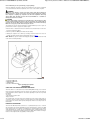
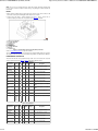
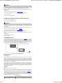
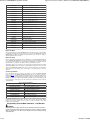
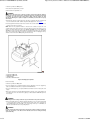
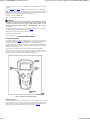
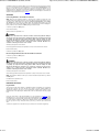
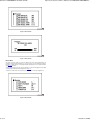
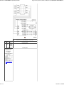
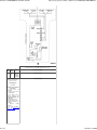
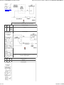
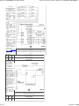
1
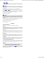
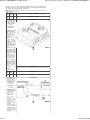
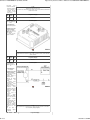
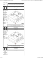
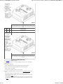
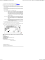
524164719-2200YRM0928-(07-2010)-US-EN
1 of 33
http://www.yaleaxcessonline.com/lib/service/US/EN/html/2200YRM0928...
CURTIS 1297
TRANSISTOR MOTOR
CONTROLLER
MPE080-E [A890]; MPW080-E [A891];
MPW065-E [A894]; MPE060-E [A896];
MPW060-E [A897]; MTR005-E [A902];
MTR007-E [A903]; MPC060-E [A904];
MPC080-E [A905]
SAFETY PRECAUTIONS
MAINTENANCE AND REPAIR
• When lifting parts or assemblies, make sure all slings, chains, or cables are correctly
fastened, and that the load being lifted is balanced. Make sure the crane, cables, and
chains have the capacity to support the weight of the load.
• Do not lift heavy parts by hand, use a lifting mechanism.
• Wear safety glasses.
• DISCONNECT THE BATTERY CONNECTOR before doing any maintenance or repair on
electric lift trucks. Disconnect the battery ground cable on internal combustion lift trucks.
• Always use correct blocks to prevent the unit from rolling or falling. See HOW TO PUT
THE LIFT TRUCK ON BLOCKS in the Operating Manual or the Periodic Maintenance
section.
• Keep the unit clean and the working area clean and orderly.
• Use the correct tools for the job.
• Keep the tools clean and in good condition.
• Always use YALE APPROVED parts when making repairs. Replacement parts must meet
or exceed the specifications of the original equipment manufacturer.
• Make sure all nuts, bolts, snap rings, and other fastening devices are removed before
using force to remove parts.
• Always fasten a DO NOT OPERATE tag to the controls of the unit when making repairs, or
if the unit needs repairs.
• Be sure to follow the WARNING and CAUTION notes in the instructions.
• Gasoline, Liquid Petroleum Gas (LPG), Compressed Natural Gas (CNG), and Diesel fuel
are flammable. Be sure to follow the necessary safety precautions when handling these
fuels and when working on these fuel systems.
• Batteries generate flammable gas when they are being charged. Keep fire and sparks
away from the area. Make sure the area is well ventilated.
4/29/2013 7:30 PM
524164719-2200YRM0928-(07-2010)-US-EN
2 of 33
http://www.yaleaxcessonline.com/lib/service/US/EN/html/2200YRM0928...
NOTE: The following symbols and words indicate safety information in
this manual:
WARNING
Indicates a hazardous situation which, if not avoided, could result in
death or serious injury.
CAUTION
Indicates a hazardous situation which, if not avoided, could result in
minor or moderate injury and property damage.
On the lift truck, the WARNING symbol and word are on orange
background. The CAUTION symbol and word are on yellow
background.
TABLE OF CONTENTS
General
Safety Precautions
Description
Curtis PMC 1297 Transistor Motor Controller
Principles of Operation
Install
Programming Controller
1307 Programmer Handset
Description/Features
Scroll Display Keys
Change Value Keys
More Info Key
Operation
Connecting Handset to Traction Motor Controller
Disconnecting Handset From Traction Motor Controller
Programmer Self-Test
Menu Selections
Program Menu
Test Menu
Diagnostics Menu
Diagnostic History
Special Program Menu
Programming Traction Motor Controller - 1307 Handset
1311 Programmer Handset
Description/Features
Menu Navigation Key
Data Increase/Decrease Key
Bookmark Keys
Operation
Connecting Handset to Traction Motor Controller
Disconnecting the Handset From the Traction Motor Controller
Main Menu Selections
Program Menu
Monitor Menu
Faults Menu
Functions menu
Information Menu
Programmer Setup Menu
Programming the Traction Motor Controller - 1311 Handset
Parameters
Adjusting Parameters
Top Speed
Acceleration
Neutral Braking
Plug Braking
Coast Braking (MPE060-E/MPE080-E Only)
Empty Volts
Battery Discharge Indicator (BDI)/Hourmeter
LED Fault Codes
Control Card Functional Test
This section is for the following models:
MPE080-E [A890];
MPW080-E [A891];
MPW065-E [A894];
MPE060-E [A896];
MPW060-E [A897];
MTR005-E [A902];
MTR007-E [A903];
MPC060-E [A904];
MPC080-E [A905]
General
This section describes the Curtis 1297 Transistor Motor Controller. Procedures are outlined for
controller programming and troubleshooting.
SAFETY PRECAUTIONS
WARNING
Disconnect the battery and separate the connectors before opening the compartment cover or
inspecting or repairing the electrical system. If a tool causes a short circuit, the high current
4/29/2013 7:30 PM
524164719-2200YRM0928-(07-2010)-US-EN
3 of 33
http://www.yaleaxcessonline.com/lib/service/US/EN/html/2200YRM0928...
flow from the battery can cause personal injury or property damage.
All checks, adjustments, and repairs in the drive unit compartment are done with the compartment
cover removed. Remove the drive unit compartment cover for access to the electrical components.
WARNING
The capacitor in the transistor controller can hold an electrical charge after the battery has
been disconnected. To prevent electrical shock and personal injury, discharge the capacitor
before inspection or repairing any component in the drive unit compartment. Wear safety
glasses. Make certain the battery has been disconnected. DO NOT use a screwdriver to
discharge the traction motor controller.
CAUTION
To avoid controller damage, always disconnect the battery before disconnecting any cables
from the controller. Discharge the capacitor, and never put power to the controller with any
power wire disconnected. Never short any controller terminal or motor terminal to the battery.
Make sure to use proper procedure when servicing the controller.
The following steps must be followed to discharge the capacitors before any checks or repairs are
performed on the controller or any part of the electrical system.
1. Block the wheels so that the truck will not roll or block the truck so that the wheels are off the floor.
See How to Put Lift Truck on Blocks.
2. Turn the key switch to the OFF position and disconnect the battery.
3. Discharge the capacitors in the controller by connecting a 200-ohm, 2-watt resistor across the
controller’s B+ and B− terminals using two insulated jumper wires. See Figure 1.
NOTE: DO NOT use any other method of discharging the capacitors. Remove the 200-ohm, 2-watt
resistor before reconnecting the battery.
1.
2.
3.
4.
POSITIVE CONNECTION
NEGATIVE CONNECTION
JUMPER WIRES
200-OHM, 2-WATT RESISTOR
Figure 1. Discharging the Capacitors
Description
CURTIS PMC 1297 TRANSISTOR MOTOR CONTROLLER
The Curtis controller is a solid state DC motor controller utilizing SEM technology. It can control the
traction motor, brake, and hydraulic system. The controller receives inputs from the control handle by
serial communication, and direct inputs from other switches depending on model. These may include
the following:
• Key switch
• Control handle arm position switch
• High-speed switch
The controller directly controls the traction motor, lift pump motor, main contactor, and the brake (on
some models). The motor controller controls the speed of the traction motor and the hydraulic lift pump
motor operation. The controller software provides self diagnostics which are accessed by means of a
Curtis handset.
PRINCIPLES OF OPERATION
The Curtis 1297 SEM Traction Motor Controller uses a sophisticated microprocessor to control the
logic and operation of the controller, eliminating the need for forward and reverse contactors. The SEM
motor controller operates on the principle of controlling the motor field circuit and the motor armature
circuit independently. The controller has many programmable features, including maximum speed,
acceleration rate, neutral braking, and braking current limit. The SEM controller includes a full range of
features as well as diagnostic and setup capability for reliable operation.
4/29/2013 7:30 PM
524164719-2200YRM0928-(07-2010)-US-EN
4 of 33
http://www.yaleaxcessonline.com/lib/service/US/EN/html/2200YRM0928...
NOTE: There are no user-serviceable parts in the Curtis 1297 controller. No attempt should be made
to open, repair, or otherwise modify the controller. Doing so may damage the controller and will void
the warranty.
INSTALL
1. Make certain the mounting surface for the traction motor controller is clean. There should be no dirt
between the contactor panel mounting plate and the traction motor controller.
2. Connect wires and cables to controller terminals. See Figure 2. Plug J1 connector into J1
receptacle, and plug J2 connector into J2 receptacle of the traction motor controller.
1.
2.
3.
4.
5.
6.
7.
8.
9.
PUMP MOTOR TERMINAL
B+ POWER TERMINAL
J3 CONNECTOR
F2 TERMINAL
F1 TERMINAL
J2 CONNECTOR
B− POWER TERMINAL
TRACTION
J1 CONNECTOR
Figure 2. Controller With (Control) and Cable (Power) Terminals
3. Refer to Programming Controller for setup of the controller.
The motor controller controls the speed of the traction motor and the hydraulic pump motor operation.
The complete unit must be replaced if correct troubleshooting methods show that the unit is damaged.
PROGRAMMING CONTROLLER
The Curtis 1297 controller can be programmed using a Curtis 1307 or 1311 handset. The areas that
can be programmed are listed in Table 1 or Table 3 along with the adjustable ranges.
Table 1. Program Menu 1
Controller
Parameters
Units
MPE MPW
060 E 060 E
MPW Adjustable
065 E
Range
Description
M1 Brake
Current Limit
Amps
250
220
300
50 to 350 Mode 1 Braking Current Limit
M2 Brake
Current Limit
Amps
250
-
-
50 to 350 Mode 2 Braking Current Limit
M1 Acceleration
Rate
Sec
0.3
0.3
0.3
0.1 to 3.0 Mode 1 Acceleration Rate
M2 Acceleration
Rate
Sec
0.1
-
-
0.1 to 3.0 Mode 2 Acceleration Rate
M1 Deceleration
Limit
Sec
10.0
2.1
2.1
0.1 to 10.0 Mode 1 Deceleration Rate
M2 Deceleration
Limit
Sec
10.0
-
-
0.1 to 10.0 Mode 2 Deceleration Rate
M1 Max Speed
Limit
%
48
82
100
M2 Max Speed
Limit
%
100
-
-
26 to 100 Mode 2 Max Speed, as % armature
PWM
Coast Current
Limit
Amps
9
25
-
0 to 350
Restraint
Amps
5.4
9.0
11.0
Min. Field
to 40.0
BDI Empty Volts
VPC
(Volts
Per
Cell ×
100)
167
167
167
90 to Full
25 to 82
Mode 1 Max Speed, as % armature
PWM
Coast Mode Deceleration Rate
Battery VPC at 0% State of Charge
Table 2. Program Menu 1
Controller
Parameters
MPE
MPE
Units
080
080 E
(EE)
MPW
080 E
Adjustable
Range
Description
M1 Brake
Current Limit
Amps
300
300
220
50 to 350 Mode 1 Braking Current Limit
M2 Brake
Current Limit
Amps
300
300
220
50 to 350 Mode 2 Braking Current Limit
M1 Acceleration
Rate
Sec
0.3
0.3
0.3
0.1 to 3.0 Mode 1 Acceleration Rate
M2 Acceleration
Rate
Sec
0.1
1.0
-
0.1 to 3.0 Mode 2 Acceleration Rate
M1 Deceleration
Limit
Sec
10.0
10.0
2.1
0.1 to 10.0 Mode 1 Deceleration Rate
4/29/2013 7:30 PM
524164719-2200YRM0928-(07-2010)-US-EN
5 of 33
http://www.yaleaxcessonline.com/lib/service/US/EN/html/2200YRM0928...
M2 Deceleration
Limit
Sec
10.0
10.0
-
0.1 to 10.0 Mode 2 Deceleration Rate
M1 Max Speed
Limit
%
48
48
82
M2 Max Speed
Limit
%
100
100
-
Coast Current
Limit
Amps
0
0
25
0 to 350
Restraint
Amps
9.2
6.0
9.0
Min. Field
to 40.0
BDI Empty Volts
VPC
(Volts
Per
Cell ×
100)
167
167
167
90 to Full
25 to 82
Mode 1 Max Speed, as % armature
PWM
26 to 100 Mode 2 Max Speed, as % armature
PWM
Coast Mode Deceleration Rate
Battery VPC at 0% State of Charge
Table 3. Program Menu 2
Controller Parameters
MPC060 MPC080
E
E
Units
Adjustable
Range
Description
M1 Brake Current Limit
Amps
250
300
75 to 350
Mode 1 Braking
Current Limit
M2 Brake Current Limit
Amps
250
300
75 to 350
Mode 2 Braking
Current Limit
M1 Acceleration Rate
Sec
0.3
0.3
0.1 to 3.0
Mode 1 Acceleration
Rate
M2 Acceleration Rate
Sec
0.1
0.1
0.1 to 3.0
Mode 2 Acceleration
Rate
M1 Deceleration Limit
Sec
10.0
10.0
0.1 to 10.0
Mode 1 Deceleration
Rate
M2 Deceleration Limit
Sec
10.0
6.1
0.1 to 10.0
Mode 2 Deceleration
Rate
M1 Max Speed Limit
%
36
36
25 to 100
Mode 1 Max Speed,
as % armature PWM
M2 Max Speed Limit
%
100
100
25 to 100
Mode 2 Max Speed,
as % armature PWM
Coast Current Limit
Amps
25
25
25 to 350
Coast Mode
Deceleration Rate
Restraint
Amps
5.4
4.4
Min. Field to
40.0
VPC (Volts
Per Cell ×
100)
167
167
90 to Full
BDI Empty Volts
Battery VPC at 0%
State of Charge
Table 4. Program Menu 2
Controller
Parameters
Units
MTR005
E
MTR007
E
MTR007
(EE)
Adjustable
Range
M1 Brake Current
Limit
Amps
250
300
300
75 to 350
Mode 1 Braking
Current Limit
M2 Brake Current
Limit
Amps
250
300
300
75 to 350
Mode 2 Braking
Current Limit
M1 Acceleration Rate
Sec
0.3
0.3
0.3
0.1 to 3.0
Mode 1
Acceleration
Rate
M2 Acceleration Rate
Sec
0.1
1.0
1.0
0.1 to 3.0
Mode 2
Acceleration
Rate
M1 Deceleration Limit
Sec
10.0
10.0
10.0
0.1 to 10.0
Mode 1
Deceleration
Rate
M2 Deceleration Limit
Sec
10.0
6.1
6.1
0.1 to 10.0
Mode 2
Deceleration
Rate
M1 Max Speed Limit
%
36
36
48
25 to 100
Mode 1 Max
Speed, as %
armature PWM
M2 Max Speed Limit
%
100
100
100
25 to 100
Mode 2 Max
Speed, as %
armature PWM
Coast Current Limit
Amps
25
25
25
25 to 350
Coast Mode
Deceleration
Rate
Restraint
Amps
5.4
4.4
6.0
Min. Field to
40.0
VPC
(Volts
Per Cell
× 100)
167
167
167
90 to Full
BDI Empty Volts
Description
Battery VPC at
0% State of
Charge
1307 Programmer Handset
DESCRIPTION/FEATURES
4/29/2013 7:30 PM
524164719-2200YRM0928-(07-2010)-US-EN
6 of 33
http://www.yaleaxcessonline.com/lib/service/US/EN/html/2200YRM0928...
The programmer handset is a handheld tool that allows the user to program, test, and diagnose the
traction motor controller. See Figure 3. It has been designed for ease of use with eight keys to control
all functions. A MORE INFO key is included to provide more detail on any display item.
The display window contains a four-line LCD display. This display is visible in most lighting conditions.
When the programmer is in the PROGRAM, TEST, or DIAGNOSTICS mode, 4 lines of a menu are
displayed. The item at the top of the display window is the selected item (in the PROGRAM menu, the
selected item will be highlighted with a flashing arrow).
1.
2.
3.
4.
5.
6.
7.
4-LINE LCD DISPLAY WINDOW
SELECTS PROGRAM MENU
SCROLLS DISPLAY UP AND DOWN
SELECTS MORE INFO, SPECIAL PROGRAM, AND DIAGNOSTIC MENUS
SELECTS TEST MENU
SELECTS DIAGNOSTICS MENU
CHANGES VALUE OF SELECTED ITEM
Figure 3. Curtis 1307 Programmer Handset
SCROLL DISPLAY KEYS
To scroll up and down within a menu, use the 2 scroll display arrow keys. The scroll display arrow
keys can be pressed repeatedly or held down. When a key is held down, the scrolling speed increases
the longer the key is held.
To the left of the PROGRAM, TEST, and DIAGNOSTICS menu, a small scroll bar is displayed. The
scroll bar gives a rough indication of the position of the four displayed items within the entire menu.
That is, when the scroll bar is at the top of the window, the top of the menu is displayed. When
scrolling through the menu, the bar will move downward. When the bar is at the bottom, the end of the
menu has been reached.
CHANGE VALUE KEYS
The change value arrow keys increase or decrease the value of the selected menu item. There is an
LED on each arrow key to indicate when the key is active and a change is permissible. When the LED
is off, the limit setting (maximum or minimum) of the function has been reached.
The change value keys may be pressed repeatedly or held in the same manner as the scroll display
keys. The longer the key is held the faster the value changes. This allows rapid changing of any
function value.
MORE INFO KEY
The more info key is used to display additional information about the selected item and to access the
SPECIAL PROGRAM menu and the DIAGNOSTICS HISTORY menu. When the programmer is in any
of the operating modes, the more info key may be pressed to display additional information about the
selected item. Press the more info key again to return to the original list. In the PROGRAM menu, a
bar graph is displayed along with the minimum and maximum values available for the selected item. If
the minimum or maximum value has been programmed, a message replaces the bar graph, and any
dependencies are listed.
Operation
CONNECTING HANDSET TO TRACTION MOTOR CONTROLLER
NOTE: Each time the programmer handset is connected to the controller, it acquires all of the
controller function value settings and stores them in its temporary memory. This allows the user to
revert back to the original settings at any time. The SPECIAL PROGRAM menu selection RESET ALL
SETTINGS is used to revert to the original settings. Any unwanted change made to any of the function
values can be "undone" in this manner, as long as the programmer has not been unplugged or the key
switch has not been turned to the OFF position (power disconnected).
1. Turn the key switch to the OFF position.
2. Disconnect and separate battery connector.
3. Remove drive unit compartment cover.
4/29/2013 7:30 PM
524164719-2200YRM0928-(07-2010)-US-EN
7 of 33
http://www.yaleaxcessonline.com/lib/service/US/EN/html/2200YRM0928...
WARNING
The capacitor in the traction motor controller can hold an electrical charge after the battery is
disconnected. To prevent electrical shock and injury, discharge the capacitor before inspecting
or repairing any component. Wear safety glasses. Make certain the battery has been
disconnected. DO NOT use a screwdriver to discharge the traction motor controller.
NOTE: The programmer handset should only be connected and disconnected with the key switch in
the OFF position.
4. Discharge the capacitors in the controller. See Safety Precautions.
5. Connect the programmer handset to J3 connector on the traction motor controller.
6. Reconnect the battery.
7. Turn the key switch to the ON position.
DISCONNECTING HANDSET FROM TRACTION MOTOR CONTROLLER
1. Turn the key switch to the OFF position.
2. Disconnect and separate battery connector.
WARNING
The capacitor in the traction motor controller can hold an electrical charge after the battery is
disconnected. To prevent electrical shock and injury, discharge the capacitor before inspecting
or repairing any component. Wear safety glasses. Make certain the battery has been
disconnected.
3. Discharge capacitors in traction motor controller by connecting a load (such as a contactor coil or a
horn) across the controller’s B+ and B− terminals. See Figure 5.
4. Discharge the capacitors in the controller. See Safety Precautions.
5. Disconnect programmer handset from J3 connector on traction motor controller.
NOTE: The programmer handset should only be connected and disconnected with the key switch in
the OFF position.
6. Install drive unit compartment cover.
7. Reconnect battery.
PROGRAMMER SELF-TEST
You can test the programmer by displaying two special test screens. See Figure 4. Press and hold the
more info key while the programmer is powering up. During the self-test, you can toggle between the
two test screens by pressing the scroll display keys. The first screen turns on every LCD element, and
the second screen displays all the characters used in the various menus. As part of the self-test, you
can also test the keys by pressing each one and observing whether its corner LED lights up. To exit
the self-test, turn the key switch to the OFF position and then unplug the programmer.
Figure 4. Programmer Handset Self-Test
MENU SELECTIONS
Program Menu
Press the program key to enter the PROGRAM mode. The LED in the corner of the program key
illuminates to indicate that the programmer has been placed in the PROGRAM mode. The adjustable
functions are shown in the display window, 4 at a time, with the corresponding settings. The setting of
the selected item (the item at the top of the display with the flashing arrow) can be changed using the
change value keys. The change value keys have LEDs to indicate whether the key can be used to
increase or decrease the value any further.
Press the more info key to display more detailed information for the setting selected, including a bar
graph indicating the position of the current setting relative to the range for the setting, the unit of
measure, and the specific minimum and maximum values for the setting. If the range is limited by the
values assigned for a different function, the name of the limiting function is displayed in place of the
minimum and maximum values.
Test Menu
NOTE: Some tests may not apply to all models.
Press the test key to enter the TEST mode. The LED in the corner of the test key illuminates to
indicate that the programmer has been placed in the TEST mode. The TEST menu displays real-time
information about the status of the inputs, outputs, and controller temperature. See Table 5. In the
TEST mode, the item of interest does not need to be the top item in the window; it only needs to be
one of the four items displayed in the window. The TEST mode is useful for checking out the operation
of the controller during initial installation. The more info key, when used in the TEST mode, displays
additional information about the top item in the window.
Table 5. Test Menu
Test Menu Display
Description
4/29/2013 7:30 PM
524164719-2200YRM0928-(07-2010)-US-EN
8 of 33
http://www.yaleaxcessonline.com/lib/service/US/EN/html/2200YRM0928...
SYS MODE
Software info for factory troubleshooting.
BATT VOLTAGE
Battery voltage across B+ and B− in volts.
BDI %
Battery state of charge, as % of full charge.
HEAT SINK °C
Heat sink temperature in °C.
THROTTLE %
Throttle reading, as % of full throttle.
FIELD CURRENT
Traction motor field current, in amps.
ARM CURRENT
Traction motor armature current, in amps.
FIELD PWM
Traction motor field duty cycle, as %.
ARM PWM
Traction motor armature duty cycle, as %.
NEUTRAL
Neutral switch: ON or OFF
MODE INPUT
Mode 2 (M2) selected: ON or OFF.
EMR REV INPUT
Emergency reverse switch: ON or OFF.
HYD THROTTLE %
Hydraulic Throttle reading, as % of full throttle.
PUMP CURRENT
Pump motor current, in amps.
PUMP PWM
Pump motor duty cycle, as %.
LV CURRENT
Lowering valve current, in amps.
LV PWM
Lowering valve duty cycle, as %.
LIFT INPUT
Lift switch: ON or OFF.
LOWER INPUT
Lower switch: ON or OFF.
MAIN CONT
Main contactor: OPEN or CLOSED.
E/M BRAKE
Electromagnetic brake: ON or OFF.
HORN INPUT
Horn driver: ON or OFF.
LOAD HOLD
Load-hold valve driver: ON or OFF.
Diagnostics Menu
Press the diagnostics key to enter the DIAGNOSTICS mode. The LED in the corner of the diagnostics
key illuminates to indicate that the programmer has been placed in the DIAGNOSTIC mode. The
DIAGNOSTICS menu displays all currently active faults detected by the controller. It is capable of
displaying 20 different faults, 4 at a time.
Diagnostic History
Press the diagnostics key and the more info key simultaneously to enter the DIAGNOSTIC HISTORY
menu. The DIAGNOSTIC HISTORYmenu lists all of the faults observed and recorded by the controller
since the history was last cleared. Press the scroll down key to display any recorded faults. Each fault
will be listed only once, regardless of the number of times the fault may have occurred.
The diagnostic history can be cleared from the controller using the special program menu function
CLEAR DIAG HISTORY. Press the program key while holding the more info key. Press the scroll
down key until CLEAR DIAG HISTORY appears in the top line of the display. Press the more info key
again, and then press the value up key to clear the history, or the value down key to cancel the
operation.
Special Program Menu
Press and hold the more info key, then press the program key to enter the SPECIAL PROGRAM
menu. See Table 6. The SPECIAL PROGRAM menu allows the user to: return the controller to
previous settings, save controller settings to the programmer memory, load controller settings from the
programmer memory, clear diagnostic history, adjust the contrast of the programmer display, select
language, and display basic controller and programmer information. Press the scroll display key until
the desired function is on the top line. Press the more info key for information on how to make the
desired adjustment.
Table 6. Special Program Menu
Special Program Menu Display
RESET ALL SETTINGS
Definition
Revert to previous settings.
CONT SETTINGS→PROG
Save controller settings to programmer.
PROG SETTINGS→CONT
Load programmer settings to controller.
CLEAR DIAG HISTORY
Clear DIAGNOSTIC HISTORY memory.
CONTRAST ADJUSTMENT
LANGUAGE SELECTION
PROGRAMMER INFO
CONTROLLER INFO
Adjust programmer display contrast.
Select displayed language.
Display programmer information.
Display controller information.
The SPECIAL PROGRAM menu also allows the user to "clone" controllers. After one controller is
programmed with all of the desired values, the values can be saved to the programmer handset
memory. The programmer handset can then be used to load the saved values to other similar
controllers (same model number).
Programming Traction Motor Controller - 1307 Handset
WARNING
NEVER adjust function settings outside the range recommended for the specific truck model.
Program changes affect lift truck performance and operation. If function settings are changed,
make sure all operators of the lift truck know that the truck has been changed and may
operate differently.
4/29/2013 7:30 PM
524164719-2200YRM0928-(07-2010)-US-EN
9 of 33
http://www.yaleaxcessonline.com/lib/service/US/EN/html/2200YRM0928...
1. Turn the key switch to the OFF position.
2. Disconnect and separate battery connector.
3. Remove drive unit compartment cover.
WARNING
The capacitor in the traction motor controller can hold an electrical charge after the battery is
disconnected. To prevent electrical shock and injury, discharge the capacitor before inspecting
or repairing any component. Wear safety glasses. Make certain the battery has been
disconnected. Discharge the capacitors using the recommended procedures and never by any
other method.
4. Discharge the capacitors in the traction motor controller by connecting a 200-ohm, 2-watt resistor
across the controller’s B+ and B− terminals using two insulated jumper wires. See Figure 5.
5. Connect programmer handset to traction motor controller. The cord of the handset plugs into the J3
connector on the front of the controller.
NOTE: Each time the programmer handset is connected to the controller, it acquires all of the
controller function value settings and stores them in its temporary memory. This allows the user to
return to the original settings at any time. The SPECIAL PROGRAM menu selection RESET ALL
SETTINGS is used to revert to the original settings. Any unwanted change made to any of the function
values can be "undone" in this manner, as long as the programmer has not been unplugged or the key
switch has not been turned to the OFF position (power disconnected).
1.
2.
3.
4.
POSITIVE CONNECTION
NEGATIVE CONNECTION
JUMPER WIRES
200-OHM, 2-WATT RESISTOR
Figure 5. Discharging the Capacitors
6. Reconnect battery.
7. Turn the key switch to the ON position.
8. Press the program key on programmer handset. The green LED in the corner of the program key
lights up to indicate the handset has been placed in the PROGRAM mode.
9. Press the scroll display keys, as required, until the desired function is shown on the top line of the
display.
10. Press the more info key to display additional information, if desired, on the selected function. The
green LED in the corner of the more info key lights up to indicate that the MORE INFO option has
been selected.
WARNING
NEVER adjust function settings outside the range recommended for the specific truck model.
11. Press the change value key to change the function value higher or lower, as required. A green LED
on each change value key lights up to indicate that the function value can be changed in the
corresponding direction. If the green LED on one of the change value keys is not illuminated, the
value has reached the limit for the corresponding direction.
WARNING
Program changes affect lift truck performance and operation. If function settings are changed,
make sure all operators of the lift truck know that the truck has been changed and may
operate differently.
4/29/2013 7:30 PM
524164719-2200YRM0928-(07-2010)-US-EN
10 of 33
http://www.yaleaxcessonline.com/lib/service/US/EN/html/2200YRM0928...
12. Press the more info key to return to the PROGRAM menu if the MORE INFO screen had been
selected.
13. Repeat Step 9 through Step 12, as required, until all of the functions are set to the desired values.
NOTE: Any unwanted change made to any of the function values can be "undone" using the SPECIAL
PROGRAM menu selection RESET ALL SETTINGS, as long as the programmer has not been
unplugged or the key switch has not been turned off (power disconnected).
14. Turn the key switch to the OFF position.
15. Disconnect and separate battery connector.
WARNING
The capacitor in the traction motor controller can hold an electrical charge after the battery is
disconnected. To prevent electrical shock and injury, discharge the capacitor before inspecting
or repairing any component. Wear safety glasses. Make certain the battery has been
disconnected. Discharge the capacitors using the recommended procedures and never by any
other method.
16. Discharge capacitors in controller by connecting a 200-ohm, 2-watt resistor across the controller’s
B+ and B− terminals with two insulated jumper wires. See Figure 5.
17. Disconnect programmer handset cord from traction motor controller.
18. Install drive unit compartment cover.
19. Reconnect battery.
1311 Programmer Handset
DESCRIPTION/FEATURES
The programmer handset is a handheld tool that allows the user to program, test, and diagnose the
traction motor controller. See Figure 6. It has been designed for ease of use with a menu navigation
key, a data increase/decrease key, and 3 bookmark keys to control all programmer functions.
The display window contains a 7-line, 128 × 64 pixel LCD screen that is capable of displaying both text
and graphics simultaneously. The window is visible in most lighting conditions and can be adjusted
using the programmer setup menu.
The programmer is menu driven and accesses submenus by pressing the menu navigation key.
When the programmer is connected to the motor controller, all current motor controller information is
uploaded into the 1311 programmer handset and ready for viewing. This upload is used by the
programmer to generate menu items that will be displayed by the programmer.
Figure 6. Curtis Model 1311 Programmer Handset
Menu Navigation Key
The menu navigation key is a 4-position switch that allows you to move up and down a menu list using
the up or down arrows, or you can open and close submenus using the right and left arrows. Use the
menu navigation key to move up or down through the main menu items. There is a blinking square on
the left side of the programmer that indicates the current menu selection. See Figure 7.
4/29/2013 7:30 PM
524164719-2200YRM0928-(07-2010)-US-EN
11 of 33
http://www.yaleaxcessonline.com/lib/service/US/EN/html/2200YRM0928...
Figure 7. Menu Selection
After selection of a main menu item, submenus for the main selection can be opened using the right
arrow. See Figure 8. As submenus are opened, a new series of indicator boxes will appear with a
blinking square to indicate the current submenu selection. You can move up and down within the
submenus using the up and down arrows. Pressing the left arrow will return the programmer to the
main menu. Pressing the right arrow while in a submenu will bring up an additional information screen
about the submenu item previously selected. See Figure 9.
Figure 8. Menu Selection
Figure 9. Menu Selection
Data Increase/Decrease Key
The data increase/decrease key allows the adjustment of various parameter settings. Press the (+)
side of the data increase/decrease key to increase a value or press the (−) side of the data
increase/decrease key to decrease a value. See Figure 6.
Bookmark Keys
There are 3 bookmark keys that can be set by the user. These keys allow you to bookmark your
position within the menu structure, allowing you to quickly return to a selection without having to
4/29/2013 7:30 PM
524164719-2200YRM0928-(07-2010)-US-EN
12 of 33
http://www.yaleaxcessonline.com/lib/service/US/EN/html/2200YRM0928...
re-navigate the entire menu structure. While you are positioned at a menu item you want to bookmark,
press one of the bookmark keys and hold it down for 4 seconds until the BOOKMARK SET screen
appears. You can return to this preset menu item at any time by pressing the bookmark key you
assigned to this item. Bookmarks are permanently retained in the programmer memory. Once the
programmer has been unplugged or power to the controller has been interrupted, the bookmarks are
cleared from the programmer memory. See Figure 6.
OPERATION
Connecting Handset to Traction Motor Controller
NOTE: Each time the programmer handset is connected to the controller, it acquires all of the
controller function value settings and stores them in its temporary memory. This allows the user to
revert back to the original settings at any time. The SPECIAL PROGRAM MENU selection RESET
ALL SETTINGS is used to revert to the original settings. Any unwanted change made to any of the
function values can be undone in this manner, as long as the programmer has not been unplugged or
the key switch has not been turned to the OFF position (power disconnected).
1. Turn the key switch to the OFF position.
2. Disconnect the battery.
3. Remove drive unit compartment cover.
WARNING
The capacitor in the traction motor controller can hold an electrical charge after the battery is
disconnected. To prevent electrical shock and injury, discharge the capacitor before inspecting
or repairing any component. Wear safety glasses. Make certain the battery has been
disconnected. Discharge the capacitors in the controller by connecting a load (such as a
contactor coil or a horn) across the controller’s B+ and B− terminals. DO NOT use a
screwdriver to discharge the traction motor controller.
4. Discharge the capacitors in the controller.
5. Connect programmer handset to the 4-pin Molex™ connector on the traction motor controller.
6. Reconnect the battery.
7. Turn the key switch to the ON position.
Disconnecting the Handset From the Traction Motor Controller
1. Turn the key switch to the OFF position.
2. Disconnect the battery.
WARNING
The capacitor in the traction motor controller can hold an electrical charge after the battery is
disconnected. To prevent electrical shock and injury, discharge the capacitor before inspecting
or repairing any component. Wear safety glasses. Make certain the battery has been
disconnected. Discharge the capacitors in the controller by connecting a load (such as a
contactor coil or a horn) across the controller’s B+ and B− terminals. DO NOT use a
screwdriver to discharge the traction motor controller.
3. Discharge the capacitors in the controller.
4. Disconnect programmer handset from the 4-pin Molex™ connector on the traction motor controller.
NOTE: The programmer handset should only be connected and disconnected with the key switch in
the OFF position.
5. Install drive unit compartment cover.
6. Reconnect the battery.
MAIN MENU SELECTIONS
Program Menu
The program menu will contain submenus of adjustable parameters downloaded to the programmer
from the motor controller. The motor controller can be setup for specific operating conditions by
changing the parameters that can be accessed through the program menu selections. Those
parameters that can be adjusted by the handset will be shown as submenu items under the program
menu.
Use the up or down arrow on the menu navigation key to select a parameter. See Figure 10. Press
the right arrow key to access the detail screen for the selected parameter. See Figure 11. The detail
screen will show the measurement units, min/max range for the parameter, and a bar graph indicating
the current parameter setting. The setting may be changed using the data increase/decrease key.
Press the (+) side of the key to increase the value or press the (−) side of the key to decrease the
value.
To return to the program menu or the main menu, press the left arrow on the menu navigation key.
4/29/2013 7:30 PM
524164719-2200YRM0928-(07-2010)-US-EN
13 of 33
http://www.yaleaxcessonline.com/lib/service/US/EN/html/2200YRM0928...
Figure 10. Menu Selection
Figure 11. Menu Selection
Monitor Menu
The monitor menu will contain a list of all truck functions that can be read and displayed by the
programmer. Using the menu navigation key, scroll up or down to select a parameter from the list.
See Figure 12. Each menu item is constantly monitored and displayed to show real-time information
about the selected function.
To view a single function in real time, press the right arrow on the menu navigation key and a detail
screen about the selected parameter will appear. See Figure 13.
To return to the monitor menu or the main menu, press the left arrow on the menu navigation key.
Figure 12. Menu Selection
4/29/2013 7:30 PM
524164719-2200YRM0928-(07-2010)-US-EN
14 of 33
http://www.yaleaxcessonline.com/lib/service/US/EN/html/2200YRM0928...
Figure 13. Menu Selection
Faults Menu
The FAULTS menu will provide the present status of the motor controller and access to past fault
history. The fault history is uploaded to the programmer when the programmer is connected to the
motor controller. Use the menu navigation key to access system faults, fault history, or to clear the
fault history. See Figure 14.
System faults will show the current state of the motor controller. See Figure 15.
Fault history will list the faults that have been stored in the motor controller memory. These faults will
be shown as descriptive text of the fault. Scroll through the faults using the up and down arrows on the
menu navigation key. See Figure 16.
CLEAR FAULT HISTORY is used to remove faults from the controller memory after review. Use the (+)
side of the data increase/decrease key to delete the faults from memory.
NOTE: You will be asked to confirm that you do want to clear the fault history. Use the (−) side of the
data increase/decrease key to cancel any action and not clear the fault history.
Figure 14. Menu Selection
Figure 15. Menu Selection
4/29/2013 7:30 PM
524164719-2200YRM0928-(07-2010)-US-EN
15 of 33
http://www.yaleaxcessonline.com/lib/service/US/EN/html/2200YRM0928...
Figure 16. Menu Selection
Functions menu
The FUNCTIONS menu is used to copy
controller to the original settings. Use the
access the SETTINGS menu. See Figure
from an existing controller and download
Figure 18.
data between motor controllers or reset the data in a
menu navigation key to select the FUNCTIONS menu to
17. From this menu you can upload the parameter block
that parameter block into another motor controller. See
Each time the programmer is connected to a motor controller, it uploads the present data from the
controller into the programmer. Using the SETTINGS menu, this original information can be
downloaded into the controller at any time to restore the controller with the original data. Any
inadvertent change in controller parameters can be undone using this feature as long as the
programmer has not been disconnected from the controller or the power has not been removed from
the controller.
Figure 17. Menu Selection
Figure 18. Menu Selection
Information Menu
The INFORMATION menu will display information about the controller. Use the menu navigation key to
select the information menu and all specific controller information will be displayed on the screen. See
Figure 19.
4/29/2013 7:30 PM
524164719-2200YRM0928-(07-2010)-US-EN
16 of 33
http://www.yaleaxcessonline.com/lib/service/US/EN/html/2200YRM0928...
Figure 19. Menu Selection
Programmer Setup Menu
The PROGRAMMER SETUP menu contains several items that can be viewed, setup, or customized to
the user’s preference. See Figure 20.
Figure 20. Menu Selection
Programming the Traction Motor Controller - 1311 Handset
WARNING
NEVER adjust function settings outside the range recommended for the specific truck model.
See Table 1 or Table 3.
Program changes affect lift truck performance and operation. If function settings are changed,
make sure all operators of the lift truck know that the truck has been changed and may
operate differently.
1. Turn the key switch to the OFF position.
2. Disconnect and separate the battery connector.
3. Remove drive unit compartment cover.
WARNING
The capacitor in the traction motor controller can hold an electrical charge after the battery is
disconnected. To prevent electrical shock and injury, discharge the capacitor before inspecting
or repairing any component. Wear safety glasses. Make certain the battery has been
disconnected. Discharge the capacitors using the recommended procedures and never by any
other method.
4. Discharge the capacitors in the traction motor controller by connecting a 200-ohm, 2-watt resistor
across the controller’s B+ and B− terminals using two insulated jumper wires.
5. Connect programmer handset to traction motor controller. The cord of the handset plugs into the J3
connector on the front of the controller.
NOTE: Each time the programmer handset is connected to the controller, it acquires all of the
controller function value settings and stores them in temporary memory. This allows the user to return
to the original settings at any time. Any unwanted change made to any of the function values can be
undone in this manner, as long as the programmer has not been unplugged or the key switch has not
been turned to the OFF position (power disconnected).
6. Reconnect the battery.
7. Turn the key switch to the ON position.
8. Select the PROGRAM menu on the programmer handset.
9. Use the up or down arrows on the menu navigation key to scroll until the desired function is
reached.
10. Press the right arrow on the menu navigation key to enter the function being changed.
WARNING
NEVER adjust function settings outside the range recommended for the specific truck model.
4/29/2013 7:30 PM
524164719-2200YRM0928-(07-2010)-US-EN
17 of 33
http://www.yaleaxcessonline.com/lib/service/US/EN/html/2200YRM0928...
See Table 1 or Table 3.
11. Using the data increase/decrease key, change the function setting to the new setting. Pressing the
(+) side of the key will increase the parameter value. Pressing the (−) side of the key will decrease
the parameter setting.
WARNING
Program changes affect lift truck performance and operation. If function settings are changed,
make sure all operators of the lift truck know that the truck has been changed and may
operate differently.
12. Press the left arrow on the menu navigation key to return to the PARAMETERS menu.
13. Repeat Step 8 through Step 12, as required, until all of the functions are set to the desired value.
NOTE: Any unwanted change made to any of the function values can be undone using the RESET ALL
SETTINGS from the FUNCTIONS menu as long as the programmer has not been unplugged or the
key switch has not been turned to the OFF position (power disconnected).
14. Turn the key switch to the OFF position.
15. Disconnect the battery connector.
WARNING
The capacitor in the traction motor controller can hold an electrical charge after the battery is
disconnected. To prevent electrical shock and injury, discharge the capacitor before inspecting
or repairing any component. Wear safety glasses. Make certain the battery has been
disconnected. Discharge the capacitors using the recommended procedures and never by any
other method.
16. Discharge the capacitors in the traction motor controller by connecting a 200-ohm, 2-watt resistor
across the controller’s B+ and B− terminals using two insulated jumper wires.
17. Disconnect the programmer handset from the controller.
18. Install the drive unit compartment covers.
19. Reconnect the battery.
Parameters
ADJUSTING PARAMETERS
NOTE: M2 parameters do not apply to MPW060E, MPW065E, and MPW080E.
Top Speed
The M1 Max Speed parameter adjusts the top speed of the truck when in Walk mode. The M2 Max
Speed parameter adjusts the top speed of the truck when in Rabbit mode. Decrease this setting to
reduce the top speed and increase this setting to raise the top speed of the truck. The M1 adjustable
range is from 25% to 48%. The M2 adjustable range is from 25% to 100%.
Acceleration
The M1 Accel Rate and the M2 Accel Rate parameters adjust the acceleration of the truck. This is true
in both Walk and Rabbit modes or M1 and M2. Decrease this setting to quicken the acceleration of the
truck, and increase this setting to soften the acceleration of the truck. The adjustable range is from 0.1
to 3.0 sec.
Neutral Braking
The M1 Decel Rate and the M2 Decel Rate parameters adjust the response of the truck when
returning to neutral. Decrease this setting to strengthen the neutral braking of the truck, and increase
this setting to weaken the neutral braking of the truck. The adjustable range is from 0.1 to 10.0 sec.
Plug Braking
The M1 Brake C/L and the M2 Brake C/L parameters adjust the response of the truck when plug
braking. Decrease this setting to soften the plug braking of the truck, and increase this setting to
strengthen the plug braking of the truck. The adjustable range is from 75 amps to 350 amps.
Coast Braking (MPE060-E/MPE080-E Only)
The Coast C/L parameter adjusts the response of the truck when releasing the quick pick switch.
Decrease this setting to soften the coast braking of the truck, and increase this setting to strengthen
the coast braking of the truck. The adjustable range is from 25 amps to 350 amps.
Empty Volts
The BDI Empty Volts parameter sets the voltage considered to be a 0% state of charge. If using
sealed, maintenance-free batteries, set this parameter to 190. Otherwise, leave at factory setting.
Battery Discharge Indicator (BDI)/Hourmeter
The 8-character LCD on the optional BDI/Hourmeter displays provides a continuous sequence of
hourmeter, battery state of charge, and fault messages. See Figure 21. Fault messages are displayed
using the same codes that are flashed by the controller’s LED. For example, code "3,2" (Main
Contactor Welded) appears as CODE 32.
4/29/2013 7:30 PM
524164719-2200YRM0928-(07-2010)-US-EN
18 of 33
http://www.yaleaxcessonline.com/lib/service/US/EN/html/2200YRM0928...
Figure 21. BDI/Hourmeter
LED Fault Codes
The Curtis 1297 controller has a Status LED built into it and can be seen through a window in the label
on top of the controller. This Status LED displays fault codes. During normal operation, with no faults
present, the Status LED flashes steadily on and off like a heartbeat. If the controller detects a fault, a
two-digit fault identification code is flashed until the fault is corrected. For example, code "3,2" (Main
Contactor Welded) appears as: 3 flashes, short pause, 2 flashes, long pause; repeat.
NOTE: Only one fault is recognized and indicated at a time by the Status LED. Multiple faults may be
read using the programmer handset. See 1307 Programmer Handset.
The 3 most common Status LED messages are shown in Table 7.
Table 7. Status LED Fault Codes
LED Codes
Description
LED
Off
No power or
defective
controller
Solid
On
Controller or
microprocessor
fault
0,1
Controller
operational; no
known faults
Fault codes 11, 13, 23, 32, 34, or 42 may intermittently appear during truck use. These signals may be
sent as a result of power loss to the 1297 controller from the battery. Turning the key switch OFF and
then ON again will usually clear these fault codes. If the codes remain after cycling the key switch, the
lift truck must be serviced.
If these intermittent faults continually appear, perform the following checks:
• Check for loose cable connections at the battery cable connectors.
• Check for loose wiring and wire connectors at the controller.
• Check for loose cable connections at the battery.
• Check battery cells for proper voltage and state of charge.
If a loose wire or connection if found, make the necessary repairs before returning the truck to service.
4/29/2013 7:30 PM
524164719-2200YRM0928-(07-2010)-US-EN
19 of 33
http://www.yaleaxcessonline.com/lib/service/US/EN/html/2200YRM0928...
Fault codes 20, 32, or 34 may also intermittently appear after the battery has been changed. If the
BDI indicator will not reset, this may indicate that the battery is not properly charged. Always install
fully charged, properly functioning batteries to the lift truck.
NOTE: Minimum reset voltage for the BDI is 25.2 volts (open cell), specific gravity should be
approximately 1.250 per cell.
LED
Dash
Model
Code Display
LED
OFF
All
Condition
Truck, dash display,
controller LED are
inoperative with the key
switch in the ON
position.
Programmer Display
Handset Does Not Operate
Circuit Description
Truck Response
No Operation
Possible Causes and
Test Procedures
1. B+ or B− is missing
at the controller.
Confirm battery is
connected.
Confirm
correct
battery voltage.
Check continuity of
battery
cables
between battery and
controller.
2. Verify the key switch
is in the ON position.
3. Check condition of
FU 1.
Refer to the section
Electrical System
2200 YRM 1052 or
Electrical System
2200 YRM 929,
Fuses.
4. Check for battery
voltage at pin #J1-1.
Verify key switch is
in the ON position.
Check condition of
FU 2. Refer to
Electrical System
2200 YRM 1052 or
Electrical System
2200 YRM 929,
Fuses.
5. Defective motor
controller.
Replace controller.
LED
Dash
Model
Code Display
1,1
Code
11
All
Condition
Handset is plugged into
the traction motor
controller. Key switch is
in the ON position.
Diagnostic menu is
selected.
Logic
This will occur when there is no power to the controller or the controller is defective.
Programmer Display
Drive Sensor
Circuit Description
Truck Response
No Traction
Possible Causes and
Test Procedures
1. Incorrect traction
motor wiring.
Check
wiring
to
traction motor.
Loose, worn, or
frayed wires?
Motor
wiring
correctly installed?
2. Check for motor
shorted to frame.
Disconnect
leads
from motor.
Resistance between
frame and motor
terminal should be 1
mega ohm or more.
3. Check for controller
shorted to B−.
4/29/2013 7:30 PM
524164719-2200YRM0928-(07-2010)-US-EN
20 of 33
http://www.yaleaxcessonline.com/lib/service/US/EN/html/2200YRM0928...
Disconnect
motor
leads from controller.
Logic
Resistance between
Traction motor current sensor error.
motor terminals on The controller uses the traction motor current sensor to detect incorrect current in the
controller and B−
traction motor circuit.
should be 1 mega
ohm or more.
LED
Dash
Model
Code Display
1,2
Code
12
Programmer Display
HW Failsafe
All
Condition
Self Test or Watchdog
Error.
Circuit Description
Truck Response
No Controller Operation
Possible Causes and
Test Procedures
1. Turn key switch to
OFF position to reset
the controller.
2. If fault reoccurs,
replace controller.
Logic
Displayed when the internal check logic of the controller determines an internal failure
of the controller.
LED
Dash
Model
Code Display
1,3
Code
13
All
Condition
External short of
Traction motor M− to
B−.
Programmer Display
Drive M−
Circuit Description
Truck Response
No Traction
Possible Causes and
Test Procedures
1. Incorrect traction
motor wiring.
Check
wiring to
traction motor.
Ensure all wiring
connections
are
tight.
2.
Traction
motor
shorted to frame.
Disconnect
motor
leads at motor.
Measure resistance
between
motor
terminals and truck
frame. If less than 1
megohm,
replace
motor.
3.
M−
short
in
controller.
Verify
voltage
between B− and M−
to be 10% less than
nominal
battery
volts.
If greater than 10%,
replace controller.
Disconnect
motor
leads at controller.
Measure resistance
between B− and
M−.
If less than 1
megohm,
replace
controller.
LED
Dash
Model
Logic
The controller uses an internal check to ensure the traction motor M− connection is
not shorted to B− (Battery Negative).
Programmer Display
4/29/2013 7:30 PM
524164719-2200YRM0928-(07-2010)-US-EN
21 of 33
http://www.yaleaxcessonline.com/lib/service/US/EN/html/2200YRM0928...
Code Display
1,4
Code
14
MPE060E,
MPE080E,
MPW060E,
MPW065E,
MPW080E,
MPC060-E,
MPC080-E
Condition
Low current sensed in
lowering solenoid coil circuit
when lower function is
selected.
Valve Fault
Circuit Description
Truck Response
No Lowering Function
Possible Causes and Test
Procedures
1. Check wiring to the
lowering solenoid coil.
Ensure all wiring and
connectors are tight.
2. Remove wiring from
lowering solenoid coil.
Check coil resistance
across the terminals
where
wires
were
removed.
All
models
=
approximately 35 ohms.
3. Check for continuity
between key switch and
lowering coil.
4. Check for continuity
between lowering coil and
pin #J1-7 at controller.
5. Check for battery voltage
at lowering coil with key
switch closed.
Logic
The controller performs a check to ensure the presence of the lowering valve solenoid
coil. If the coil current value is less than 0.5 amps when lower function is selected, the
controller will show this fault.
LED
Dash
Model
Code Display
2,0
Code
20
All
Condition
Battery state of charge
is less than 20% of full
charge.
Programmer Display
BDI Low
Circuit Description
Truck Response
No Hoist/Lift Lockout
Possible Causes and
Test Procedures
1. Battery voltage is
low.
Check
specific
gravity of battery.
Recharge or change
battery.
Logic
Controller senses battery state of charge.
LED
Dash
Code Display
2,1
Code
21
Model
Programmer Display
MPW060E,
MPW065E,
Throttle Wiper High
4/29/2013 7:30 PM
524164719-2200YRM0928-(07-2010)-US-EN
22 of 33
http://www.yaleaxcessonline.com/lib/service/US/EN/html/2200YRM0928...
MPW080E,
MPE060E,
MPE080E
Condition
Voltage from the throttle
handle is too high.
Circuit Description
Truck Response
No Traction
Possible Causes and Test
Procedures
1. Throttle sensor not
centered.
2. Throttle sensor input
shorted to B+.
3. Failed throttle sensor.
4. Improper parameters on
software, use handset to
verify parameters.
For testing procedures, refer
to Control Card Functional
Test in this section.
Logic
Controller checks for the throttle signal to be less than 4.8 V.
LED
Dash
Code Display
2,1
Code
21
Model
Programmer Display
MTR005-E,
MTR007-E,
MPC060-E,
MPC080-E
Throttle Wiper High
Condition
Voltage from the throttle
sensor is too high.
Circuit Description
Truck Response
No Traction
Possible Causes and Test
Procedures
1. Throttle sensor not
centered.
Center the sensor at the
control handle.
Sensor output = 2.5 V
when centered. See
Electrical System 2200
YRM 1052 .
2. Failed throttle sensor or
Interface
module
defective.
Contact Resident Service
Engineering through the
Contact
Management
System.
4/29/2013 7:30 PM
524164719-2200YRM0928-(07-2010)-US-EN
23 of 33
http://www.yaleaxcessonline.com/lib/service/US/EN/html/2200YRM0928...
Logic
Controller checks for the throttle signal to be less than 4.8 V.
LED
Dash
Code Display
2,1
Code
21
Model
Programmer Display
MPW060E,
MPW065E,
MPW080E,
MPE060E,
MPE080E
Throttle Wiper Low
Condition
Voltage from the throttle
handle is too low.
Circuit Description
Truck Response
No Traction
Possible Causes and Test
Procedures
1. Throttle sensor not
centered.
2. Throttle sensor input
shorted to B−.
3. Failed throttle sensor.
4. Improper parameters on
software.
For testing procedures, refer
to Control Card Functional
Test in this section.
4/29/2013 7:30 PM
524164719-2200YRM0928-(07-2010)-US-EN
24 of 33
http://www.yaleaxcessonline.com/lib/service/US/EN/html/2200YRM0928...
Logic
Controller checks for the throttle signal to be above 0.1 V.
LED
Dash
Code Display
2,1
Code
21
Model
Programmer Display
MTR005-E,
MTR007-E,
MPC060-E,
MPC080-E
Throttle Wiper Low
Condition
Voltage from the throttle
sensor is too low.
Circuit Description
Truck Response
No Traction
Possible Causes and Test
Procedures
Throttle sensor not
centered.
Center the sensor at the
control handle.
Sensor output = 2.5 V
when centered. See
Electrical System 2200
YRM 1052.
2. Failed throttle sensor.
Replace throttle sensor.
3. Improper parameters on
software.
4.
Interface
module
defective.
5. For testing procedures
refer to Control Card
Functional Test in this
section.
1.
4/29/2013 7:30 PM
524164719-2200YRM0928-(07-2010)-US-EN
25 of 33
http://www.yaleaxcessonline.com/lib/service/US/EN/html/2200YRM0928...
Logic
Controller checks for the throttle signal to be above 0.1 V.
LED
Dash
Code Display
2,2
Code
22
Model
Programmer Display
MPE060E,
MPE080E,
MPW060E,
MPW065E,
MPW080E
Pump Sensor
Condition
Pump motor current sensor
error.
Circuit Description
Truck Response
No Lifting
Possible Causes and Test
Procedures
1. Incorrect pump motor
wiring.
Check wiring to traction
motor.
Loose, worn, or frayed
wires?
Motor wiring correctly
installed?
2. Check for motor shorted
to frame.
Disconnect leads from
motor.
1 megohm resistance
between frame and
motor terminal.
3. Check for controller
shorted to B−.
Disconnect motor leads
from controller.
1 megohm resistance
between
motor
terminals on controller
and B−.
LED
Dash
Model
Code Display
2,3
Code
23
All
Condition
High Pedal Disable
sequencing error.
Logic
The controller uses the pump motor current sensor to detect incorrect current in the
pump motor circuit.
Programmer Display
HPD
Circuit Description
4/29/2013 7:30 PM
524164719-2200YRM0928-(07-2010)-US-EN
26 of 33
http://www.yaleaxcessonline.com/lib/service/US/EN/html/2200YRM0928...
Truck Response
No Traction
Possible Causes and
Test Procedures
1. Return throttle to
neutral.
2. Ensure linkage is
allowing throttle to
return to neutral.
3. Check throttle Hall
Effect
sensor
is
centered.
Sensor output = 2.5
V when centered.
4. Check connector at
J2 is tight and pins
are in good condition.
5.
Failed
throttle
sensor.
6. Ensure continuity
through
proximity
switch.
7.
Improper
parameters
on
software,
use
handset
to
verify
parameters.
8.
For
testing
Logic
procedures refer to
The controller will not drive the motor if the throttle is more than 25% engaged at
Control
Card startup. If the controller receives a throttle input greater than 25% of full speed before
Functional Test in this
the motor is started, the controller will fault and prevent traction.
section.
LED
Dash
Code Display
2,3
Code
23
Model
Programmer Display
MPE060E,
MPE080E,
MPW060E,
MPW065E,
MPW080E
SRO
Condition
Static Return to OFF
sequencing error.
Circuit Description
Truck Response
No Traction
Possible Causes and Test
Procedures
1. Ensure proper startup
sequence
is
being
followed.
2. Return throttle to neutral.
3. Ensure linkage is allowing
throttle to return to
neutral.
4. Check throttle Hall Effect
sensor is centered.
5. Check connector at J2 is
tight and pins are in good
condition.
6. Improper parameters on
software, use handset to
verify parameters.
7. For testing procedures
refer to Control Card
Functional Test in this
section.
LED
Dash
Model
Code Display
2,3
Code
23
All
Condition
High Speed switch is
activated at startup.
Logic
The controller will not drive the motor unless the following sequence of operation is
followed. Turn key switch to ON position, activate brake switch, activate direction
switch and throttle. If direction switch and throttle are activated before key or brake
switch, controller will fault.
Programmer Display
Anti-Tiedown
Circuit Description
Truck Response
Slow Speed Only
Possible Causes and
Test Procedures
1. Check high speed
switch is open at
startup.
2. Check for voltage on
pin #J1-3.
3.
Improper
4/29/2013 7:30 PM
524164719-2200YRM0928-(07-2010)-US-EN
27 of 33
http://www.yaleaxcessonline.com/lib/service/US/EN/html/2200YRM0928...
parameters
on
software,
use
handset
to
verify
parameters.
4.
For
testing
procedures refer to
Control
Card
Functional Test in this
section.
Logic
If the high speed switch is activated at startup, the controller will fault.
LED
Dash
Code Display
2,4
Code
24
Model
Programmer Display
MPE060E,
MPE080E,
MPW060E,
MPW065E,
MPW080E
Pump M−
Condition
External short of pump
motor M− to B−.
Circuit Description
Truck Response
No Lifting
Possible Causes and Test
Procedures
1. Incorrect pump motor
wiring.
Check wiring to pump
motor.
Ensure
all
wiring
connections are tight.
2. Pump motor shorted to
frame.
Disconnect motor leads
at motor or controller.
Measure
resistance
between motor terminals
and truck frame. If less
than 1 megohm, replace
motor.
3.
Check
for
shorted
controller.
Disconnect pump motor
leads at controller.
Measure
resistance
between B− and Pump
M− at the controller. If
less than 1 megohm,
replace controller.
LED
Dash
Model
Code Display
3,0
Code
30
ALL
Condition
Brake is disconnected.
Logic
The controller uses an internal check to ensure the pump motor M− connection is not
shorted to B− (Battery Negative).
Programmer Display
EM Brake
Circuit Description
Truck Response
No Traction
Possible Causes and
Test Procedures
1. Check brake switch.
Verify
battery
voltage at pin #J1-2
when brake switch
is closed.
2. Verify B+ voltage at
the
brake
coil
connector.
3. Check for correct
brake coil resistance.
MPE080E,
MTR007E,
and
MPC080E = Approx.
10.7
ohms
MPW060E,
4/29/2013 7:30 PM
524164719-2200YRM0928-(07-2010)-US-EN
28 of 33
http://www.yaleaxcessonline.com/lib/service/US/EN/html/2200YRM0928...
MPW080E,
MPE060E,
MTR005E,
and
MPC060E = Approx.
14.0 ohms
MPW065E
=
Approx. 4.0 ohms
If open or shorted,
replace coil.
4. Check voltage at pin
#J1-12
and
pin
#J1-20.
Voltage
should be less than
battery voltage.
5. If brake still cannot
be energized, replace
controller.
Logic
Controller will output battery volts at pin #J1-20 when brake switch is closed. The
controller monitors the current in the brake circuit and will fault if overcurrent occurs.
LED
Dash
Code Display
3,1
Code
31
Model
Programmer Display
MPE060E,
MPE080E,
MPW060E,
MPW065E,
MPW080E
Analog MUX Fault
Condition
Controller has lost
communication with the
control handle logic card.
Circuit Description
Truck Response
No Traction
Possible Causes and Test
Procedures
Ensure the cable is
connected to the J2 plug
on the controller.
2. Verify all pin connections
are tight and making
contact.
3. Verify correct connector
wiring.
4. Check continuity of the
wires running from the
controller to the control
handle logic card.
Verify continuity while
rotating
the
control
handle arm from side to
side.
5. Check for control handle
wiring grounded to the
truck frame.
6.
Check
for
correct
operation of the control
handle logic card.
Use
handheld
programmer to verify
signals from the control
handle logic card are
being received by the
controller.
7. Improper parameters on
software, use handset to
verify parameters.
8. For testing procedures
refer to Control Card
Functional Test in this
section.
1.
LED
Dash
Code Display
3,1
Code
31
Logic
The control handle logic card communicates with the controller through the cable
between the logic card and the J2 connection on the controller. All signals for speed,
direction, emergency reverse, horn, and lift/lower are sent to the controller over this
cable.
Model
Programmer Display
MTR005-E,
MTR007-E,
MPC060-E,
MPC080-E
Analog MUX Fault
Condition
Controller has lost
communication with the
control handle interface
module.
Circuit Description
Truck Response
4/29/2013 7:30 PM
524164719-2200YRM0928-(07-2010)-US-EN
29 of 33
http://www.yaleaxcessonline.com/lib/service/US/EN/html/2200YRM0928...
No Traction
Possible Causes and Test
Procedures
1. Ensure the cable between
the controller and the
control handle interface
module
is
securely
connected.
2. Verify the cable from the
control handle is secure to
the
control
handle
interface
module
connector.
3. Verify all pin connections
are tight and making
contact.
4.
Check
for
correct
connector wiring.
5. Check continuity of the
wires running from the
control handle to the
control handle interface
module.
Verify continuity while
rotating
the
control
handle arm from side to
side.
6. Check for control handle
wiring grounded to the
truck frame.
7.
Check
for
correct
operation of the control
handle and control handle
interface module.
Use
handheld
programmer to verify
signals from the control
handle being received by
the controller.
8. Improper parameters on
software, use handset to
verify parameters.
9. For testing procedures
refer to Control Card
Functional Test in this
section.
LED
Dash
Model
Code Display
3,2
Code
32
All
Condition
The main contactor tips
are welded.
The main contactor
driver is shorted.
Logic
The control handle logic card communicates with the controller through the cable
between the control handle interface module and the J2 connection on the controller.
All signals for speed, direction, horn, and lift/lower are sent to the controller over this
cable.
Programmer Display
Main Cont Welded
Circuit Description
Truck Response
No Traction
Possible Causes and
Test Procedures
1. Tips are welded.
Replace contactor
tips. Refer to the
section
Electrical
System 2200 YRM
1052 or Electrical
System 2200 YRM
929, Repairs.
2. Tips are not welded
and contactor is being
held closed by the
controller at startup.
Replace controller.
3. Check traction motor
terminal block for
cracks.
4. Verify that traction
motor brush leads are
tight.
5. Verify that traction
motor brushes are
free to move in brush
box.
LED
Dash
Model
Code Display
3,3
Code
33
All
Logic
The controller performs an internal check for welded contactor and missing contactor
each time the controller is turned on.
Programmer Display
Field Short
4/29/2013 7:30 PM
524164719-2200YRM0928-(07-2010)-US-EN
30 of 33
Condition
Traction motor field
windings are shorted.
http://www.yaleaxcessonline.com/lib/service/US/EN/html/2200YRM0928...
Circuit Description
Truck Response
No Traction
Possible Causes and
Test Procedures
1. Check field windings
at traction motor for
shorted condition.
2. Check for continuity
between the FU 1 or
FU 2 terminal and the
motor frame. Refer to
the section Electrical
System 2200 YRM
1052 or Electrical
System 2200 YRM
929, Fuses.
There should be no
continuity.
If
Logic
continuity
is
The controller checks for resistance in the field windings of the motor. If no resistance
measured, replace
is seen, the controller will fault.
traction motor.
LED
Dash
Model
Code Display
3,3
Code
33
All
Condition
The traction motor field
coil circuit is open.
Programmer Display
Field Open
Circuit Description
Truck Response
No Traction
Possible Causes and
Test Procedures
1.
Ensure
wiring
connections
are
secure.
2. Remove wires from
the FU 1 and FU 2
terminals
and
measure resistance
between FU 1 and FU
2. Refer to the
section
Electrical
System 2200 YRM
1052 or Electrical
System 2200 YRM
929, Fuses.
If high resistance is
measured, replace
traction motor.
LED
Dash
Model
Code Display
3,4
Code
34
All
Condition
Missing main contactor.
Logic
The controller checks for resistance in the traction motor field coil circuit. If no
resistance is seen, the controller will fault.
Programmer Display
Missing Contactor
Circuit Description
Truck Response
No Operation
Possible Causes and
Test Procedures
1. Ensure all wiring
connections to the
main contactor are
secure and tight.
2. Check FU 2. Refer
to
the
section
Electrical
System
2200 YRM 1052 or
Electrical
System
2200
YRM
929,
Fuses.
3. Check the main
contactor coil. Refer
to
the
section
Electrical
System
2200 YRM 1052 or
Electrical
System
2200
YRM
929,
Repairs.
Check
coil
resistance.
MPW065E
=
Approx. 14 ohms
4/29/2013 7:30 PM
524164719-2200YRM0928-(07-2010)-US-EN
31 of 33
http://www.yaleaxcessonline.com/lib/service/US/EN/html/2200YRM0928...
All other models =
Approx. 54 ohms
4. Check coil open or
shorted.
Replace coil.
Logic
The controller checks to ensure the main contactor circuit is completed on startup. If
the controller senses this circuit has not been completed, the controller will fault.
LED
Dash
Model
Code Display
Programmer Display
4,2
Code
42
All
Condition
Controller is sensing
voltage above present
value.
Overvoltage
Circuit Description
Truck Response
Reduced Traction
Performance
Possible Causes and
Test Procedures
1.
Operating
with
charger attached.
2. Incorrect battery
installed in truck.
3. Check condition of
battery and battery
cables.
NOTE: When truck is
subjected
to
high
regenerative
braking
currents, the fault may
appear
as
an
intermittent fault and
can be cleared by
resetting the key.
Logic
The controller monitors input voltage. When input voltage is above the controller
preset, current to the traction motor is reduced.
LED
Dash
Model
Code Display
4,2
Code
42
All
Condition
Controller is sensing
battery voltage below a
preset level.
Programmer Display
Low Battery Voltage
Circuit Description
Truck Response
Reduced Traction
Performance
Possible Causes and
Test Procedures
1.
Battery
needs
charging.
2. Check battery cables
for loose or corroded
terminals.
3. Incorrect battery
installed.
Logic
The controller monitors input voltage. When input voltage is below the controller
preset, current to the traction motor is reduced.
LED
Dash
Model
Code Display
4,3
Code
43
All
Condition
Controller heat sink is
too hot.
Programmer Display
Over Temp Cutback
Circuit Description
Truck Response
Reduced Traction
Performance
Possible Causes and
4/29/2013 7:30 PM
524164719-2200YRM0928-(07-2010)-US-EN
32 of 33
http://www.yaleaxcessonline.com/lib/service/US/EN/html/2200YRM0928...
Test Procedures
1. Operating in a
high-temperature
environment.
2. Exceeding normal
truck duty cycle.
Reduce load size.
Increase cycle time.
3.
Verify
correct
operation of heat sink
sensor.
Use
handheld
programmer
to
check that heat sink
reading
is
approximately room
temperature
after
truck has cooled to
room temperature.
Logic
The controller will reduce current to the traction motor when the controller exceeds
85°C (185°F). When controller cools below this level, normal traction performance will
return.
LED
Dash
Model
Code Display
4,3
Code
43
Programmer Display
Under Temp Cutback
All
Condition
Controller heat sink is
too cold.
Circuit Description
Truck Response
Reduced Traction
Performance
Possible Causes and
Test Procedures
1. Operation in a cold
temperature
environment.
2.
Verify
correct
operation of heat sink
sensor.
Use
handheld
programmer
to
check that heat sink
reading
is
approximately room
temperature
after
truck has cooled to
room temperature.
Logic
The controller will reduce current to the traction motor when the controller is below
−25°C (−13°F). When controller warms above this level, normal traction performance
will return.
Control Card Functional Test
Refer to Figure 22 for the following procedures.
1. Follow all safety precautions as listed at the beginning of this section prior to performing any
electrical checks.
2. Ensure Battery is fully charged.
a. Verify continuity between battery negative (at battery) and −B terminal (at controller).
3. Check for loose connections or damaged wiring between control card and controller.
a. Verify connection at the controller.
b. Very wire harness connection at the base of the steer handle.
4. Connect Curtis 1307 handset and go to tester function. Refer to 1307 Programmer Handset in this
section.
a. Look for battery voltage to be 25V approximately. If not, verify battery and connections.
b. Check for throttle accelerator output to be 95% or more at full throttle and to be at 0% at neutral
position. If not, go to Step 6.
c. Check for lift switch, fork low switch, belly switch, neutral switch (if is a legacy card version), and
horn switch input to alternate between on and off when switch is pressed and released. If not, go
to Step 6.
4/29/2013 7:30 PM
524164719-2200YRM0928-(07-2010)-US-EN
33 of 33
http://www.yaleaxcessonline.com/lib/service/US/EN/html/2200YRM0928...
d. If the above tests pass, the tiller head and the control card are good.
5. If handset does not operate, follow LED OFF instructions listed in LED Fault Codes.
6. If handset tests did not pass, open tiller head and verify connection at control card.
a. Power off the forklift and measure continuity between pin 2, on JP2, on the control card and Bat the controller. If an open or high resistance is measured, trace problem source and refer to
troubleshooting guide.
b. Power off the forklift and measure continuity between pin 1, on JP2, on the control card and B+
at the controller. If an open or high resistance is measured, trace problem source and refer to
troubleshooting guide.
c. Power on the forklift and check for 7- segment LED to light on
(1) If the LED is not lit then check power on JP2, between pin 1 and pin 2. JP2 voltage reading
shall be 14V or more, if not, then the tiller card is not receiving power from
controller. Disconnect the connection at JP1 and verify the voltage between
harness pins 1 and 2 is more than 12V. Check the wiring between the
controller and the tiller card, as well as the controller output. Reconnect and
measure voltage on JP2 again. If voltage reading is achieved on JP2, and the
7 segment display is not lit, replace the tiller card. Refer to Electrical
System 2200 YRM 929.
(2) Ensure jumper on SV2 is not on Diagnose, Teach or Configuration mode. SV2 jumper can be
either seated on parking position (P) or not present at all. If jumper is on
Diagnose, Teach or Configuration; proceed to reconfigure card through teach
mode following auto-learning procedure. Refer to Electrical System 2200
YRM 929.
(3) Ensure 7 segment LED to display the proper control handle card setting. The configuration
setting used with CURTIS controllers would be a number 7. If not, proceed to
reconfigure card through teach mode following auto-learning procedure.
Refer to Electrical System 2200 YRM 929.
d. If ON-OFF lift/lower switches did not function as expected, swap the On-Off switch with other
On-Off switch available within tiller head to verify if problem follows the switch.
7. Replace the control handle card if necessary. Refer to the section Electrical System 2200 YRM
929, Control Handle for control handle card installation and calibration procedures.
NOTE: ENSURE THAT THE CAM MAGNETIC HOLDER IS ALIGNED WITH THE ALIGNMENT
WINDOW; OTHERWISE TRACTION FUNCTIONS WILL NOT OPERATE IN ONE OF THE
DIRECTIONS.
1.
2.
3.
4.
5.
6.
7.
JUMPER TERMINALS (SV2)
HORN SWITCH (S1)
THUMBWHEEL SWITCH (CAM MAGNETIC HOLDER)
LED DISPLAY SCREEN
BELLY SWITCH (S)
TURTLE SWITCH (S2)
ALIGNMENT WINDOW (CAM MAGNETIC HOLDER)
Figure 22. Control Card
Yale Materials Handling Corp.
1400 Sullivan Dr., Greenville, NC 27834-2011
4/29/2013 7:30 PM