1
Operation Manual
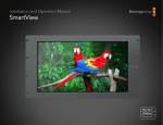
SmartView Duo
Mac OS X™
Windows™
May 2011
Contents
SmartView Duo Operation Manual
4
22
How to Install
SmartView Duo product diagram
Pre-installation overview and planning
Hardware: Optimizing the viewing angle
Hardware: SDI monitoring
Hardware: SDI connection diagram examples
Hardware: Setting Up the Network
Hardware: Networking with a direct Ethernet connection
Hardware: Networking with an Ethernet network switch
Hardware: Tally port pin connections
Software: Installing the Blackmagic SmartView Utility software
Software: Updating the firmware in your SmartView Duo
Software: Configuring Blackmagic SmartView Utility software
Network Settings pane: Device Name
Network Settings pane: Configure Address
Monitor Settings pane: Brightness, Contrast, Saturation
Monitor Settings pane: Adjust both monitors together
Monitor Settings pane: Identify monitor
Add Device
Copy/Paste Display Settings
5
6
8
10
11
12
13
14
15
16
17
18
19
19
20
20
21
20
21
Helpful Information
Support
24
23
Warranty
12 Month Warranty
25
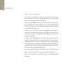
3 Welcome
Welcome to SmartView Duo.
We hope you share our dream for the television industry to become a truly creative industry by allowing
anyone to have access to the highest quality video.
Video monitoring is needed everywhere in a facility. SmartView Duo provides two beautiful 8 inch LCD
displays in a 3RU rack housing less than an inch thick. The two monitors are completely independent
and support SD, HD and even 2K video via 3 Gb/s SDI! Video monitoring is designed to work straight
out of the box and our free utility provides the user with an easy and intuitive configuration tool.
This instruction manual should contain all the information you’ll need on installing your SmartView Duo,
although it’s always a good idea to ask a technical assistant for help if you are not sure what IP addresses
are, or if you don’t know much about computer networks. SmartView Duo is easy to install, however, there
are a few slightly technical preferences you may need to set after you install it.
We think it should take you approximately 5 minutes to complete installation. Please check our web site at
www.blackmagic-design.com and click the support page to download the latest updates to this manual
and SmartView Duo software. Lastly, please register your SmartView Duo when downloading software
updates so we can keep you updated when new software is released. We are constantly working on new
features and improvements, so we would love to hear from you!
Grant Petty
CEO Blackmagic Design
4
How to Install
5 Installation
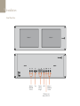
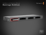
SmartView Duo
Monitor 1
Monitor 2
SD/HD-SDI
In & Out
Monitor 2
Tally
Ethernet
with loop
through
USB
Monitor 1
SD/HD-SDI
In & Out
+12V main power
supply connection
6 Installation
SmartView Duo pre-installation overview and planning
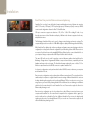
SmartView Duo is perfect for any facility which requires rack-based monitoring. It features two monitors
with 8" LCD screens, 2 SDI inputs, 2 SDI loop-through outputs, 2 Ethernet ports, tally connector, USB 2.0
connector and configuration software for Mac OS X and Windows.
SDI input connections support auto-detection of SD, HD or 3 Gb/s SDI including 2K video. Loopthrough outputs are reclocked. Simultaneous display of different video formats is supported on the two,
independent monitors.
The Blackmagic SmartView Utility can be used to change network settings and monitor settings. The
computer display resolution needs to be 1280 x 800 or higher to display the Blackmagic SmartView Utility.
While SmartView Duo displays video without needing any configuration, any network settings needs to be
configured prior to deployment. Network configuration is performed using a direct USB 2.0 connection to
a computer. You will need to provide a standard USB 2.0 type A-B male cable to connect SmartView Duo to
your computer. A laptop computer with a USB 2.0 port would be ideal for this task.
This same USB cable can be used for applying occasional firmware updates downloaded from the
Blackmagic Design website. Programmable firmware can provide new features, compatibility with new
hardware and support for new formats. The SmartView firmware update utility runs on a Mac OS X or
Windows computer and uses the USB 2.0 connection to update SmartView Duo.
Local monitor configuration can be performed with a direct USB 2.0 connection between your computer
and a SmartView Duo unit.
Remote monitor configuration can be performed via an Ethernet network switch. The network switch also
enables multiple computers to configure SmartView monitor settings. Additional SmartView Duo units can
be daisy-chained together using the active loop-through Ethernet OUT port on each unit so as to only use
a single port on your switch. Daisy-chaining SmartView Duo via Ethernet also avoids having to run Ethernet
cables back to the network switch for each SmartView Duo unit. Power must be supplied to all units for
Ethernet daisy-chaining to work.
Remote monitor configuration can also be performed via a direct Ethernet connection between your
computer and SmartView Duo. No network switch is required in this configuration which is great if you
need to install and set up SmartView Duo fast. Additional SmartView Duo units can be daisy-chained
together using the active loop-through Ethernet OUT port on each unit. Power must be supplied to all
units for Ethernet daisy-chaining to work.
7 Installation
A tally connector is provided for use with switcher and automation systems. The 9-pin D connector wiring
description is printed on the rear of the unit showing contact closures to display red, green or blue tally
borders on each, independent monitor.
If SmartView Duo is to be installed high up in an equipment rack, you may wish to physically invert the LCDs
for the optimum viewing angle. The images on the LCDs will automatically flip to the correct orientation
when they sense an inversion. A number 02 size Pozidriv screwdriver is required to disconnect and
reconnect the faceplate from its rear assembly. This is a simple procedure and does not involve opening
the rear assembly.
SmartView Duo is 3 RU (rack units) high and less than an inch deep. You will need to leave enough space in
your equipment rack to install the SmartView Duo hardware.
SmartView Duo includes a universal power supply with international power socket adapters for all countries.
To stop power from being accidentally disconnected, a cable tie point is included just below the power
socket to lock down the power connection. You will need to provide a mains power socket for the universal
power supply.
8 Installation
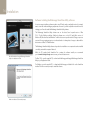
Hardware: Optimizing the viewing angle
Before you install SmartView Duo high up in a rack, it is a good idea to check the optimum viewing angle
by connecting an SDI video signal and then temporarily inverting the unit. The unit will automatically sense
the inversion and flip the video images to the correct orientation.
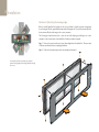
The following procedure describes how to invert the unit while keeping any labelling in the correct
orientation on the front face plate. A number 02 size Pozidriv screwdriver is required.
Step 1. Remove the screws from the top, bottom, left and right sides of SmartView Duo. There are a total
of 10 screws as indicated in the accompanying illustration.
Step 2.
You may wish to perform a test inversion, to check the
optimum viewing angle, before bolting SmartView Duo high
up in a rack.
Lift the front face plate away from the rear assembly as illustrated.
9 Installation
Step 3.
Invert the rear assembly.
Step 4.
Reinstate the face plate on the inverted rear assembly.
Step 5.
Reinstate the 10 screws in the SmartView Duo chassis.
SmartView Duo is now ready to be installed in a high position in a rack. Once bolted into a rack, SmartView
Duo will continue to display the optimum viewing angle, even if bumped, as there are no external knobs or
adjustments to mishandle or to come loose.
10 Installation
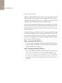
Hardware: SDI monitoring
SmartView Duo features regular BNC connectors to make it easy to connect cables from other SDI
equipment including switchers, cameras, capture cards, decks and disk recorders. After powering on the
SmartView Duo and connecting an SDI video source to one of the SDI In connectors, the video should
immediately be visible on the corresponding monitor and no configuration is required.
Each monitor has its own, independent, 3 Gb/s SDI input as well as a loop-through output. SD, HD and 2K
signals are automatically detected and supported by the SDI input and loop-through connections. When
multiple SmartView Duo units are daisy-chained together via SDI, all units must be powered on to support
the loop-through SDI output.
The independent monitors on each SmartView Duo enable one monitor to display a YUV 4:2:2 signal
while the other receives RGB 4:4:4. One monitor could be showing NTSC while the other shows PAL. One
monitor could be showing HD while the other shows 2K. There are many possible combinations but it is
all as simple as connecting a single SDI cable to each monitor. Following are two examples of different SDI
signals connecting to SmartView Duo simultaneously.
Example 1: Connecting a 4:2:2 SDI or HD-SDI source
The illustration on the following page shows the SDI output of an HyperDeck Shuttle disk recorder
connected to an SDI IN port on SmartView Duo. The HyperDeck Shuttle can send standard definition
or high definition YUV 4:2:2 video to SmartView Duo.
Example 2: Connecting a dual-link 4:4:4 HD or 2K-SDI source
If you wish to view an RGB 4:4:4 dual-link HD-SDI or dual-link 2K-SDI signal on SmartView Duo, you will
need to use a dual-link to single-link SDI converter such as an HDLink Pro from Blackmagic Design.
The illustration on the following page shows the dual-link HD-SDI outputs of a Sony HDCAM SR
deck converted to a 3 Gb/s SDI signal, by HDLink Pro, and then connected to an SDI IN port on
SmartView Duo.
11 Installation
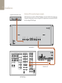
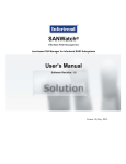
Hardware: SDI connection diagram examples
HyperDeck Shuttle disk recorder
+12V POWER
HDMI IN
HDMI OUT
SDI IN
This illustration shows two examples of different SDI hardware connected to SmartView Duo simultaneously.
The HyperDeck Shuttle disk recorder is providing a YUV 4:2:2 signal at the same time that the HDCAM SR
deck is providing an RGB 4:4:4 signal.
SDI OUT
SmartView Duo
"ÊÉ"
/ÊÉ"Ê-É1®
1"Ê"1/*1/
£
Ó
Î
" /",Ê"1/*1/
,
1
,Ê *1/
{
£
/Ê
"
/ÊÉ"
"1/*1/
1"
£ÉÓ
ÎÉ{
£ÉÓ
ÎÉ{
xÉÈ
ÇÉn
xÉÈ
ÇÉn
É£ä
££É£Ó
É£ä
££É£Ó
Ê-Ê *1/
Ê"1/Ê
*1/
" /",
£
Ê *1/
"*/" ® " /",
Ó
"1/
Ê,Ê"1/
£
*1/
1"
Ó
-9 ,"/ÊÓÊ*,ÊÉ"Êxä*®
"1/
Ó
Ê-Ê"1/*1/
£
Ó
" /",
-Ê"1/
"*"-/
" /",®
,"/Ê£ Ê*®
,"/Ê£ É"1/Ê*®
,-{ÓÓ
6"Ê
" /,"
"*/" ® "*/" ® "*/" ®
",/Ê
" 6°Ê"1/Ê"*/" ®
£
" /",
Ó
-Ê-Ê"1/*1/
£
1-
HDCAM SR deck
Ó
" /",
HDLink Pro 3D
12 Installation
Hardware: Setting Up the Network
It is not necessary to connect SmartView Duo to a computer in order to view SDI video and you can skip this
section if you simply want to view video without making any adjustments. However if you wish to remotely
adjust the monitor settings, a network connection will be required.
SmartView Duo has two 10/100Base-T Ethernet ports. You can connect the IN port to a network switch or
directly to an Ethernet port on your computer. The OUT port can be connected to additional SmartView
Duo units or to other network devices such as a Videohub router. Power must be supplied to all SmartView
Duo units for Ethernet daisy-chaining to work.
If you want to connect several SmartView Duo units without using IP addresses from your existing studio
network, or if you don't have an existing network, simply connect them directly to the Ethernet port on your
computer. This is also a fast way to connect SmartView Duo units via Ethernet as you don't need to run any
cables back to a network switch.
If you want to connect several SmartView Duo units to your studio's network, you only need to connect one
SmartView Duo to the network switch and the rest can be daisy-chained to each other so you don't have to
run multiple cables back to a network switch. Power must be supplied to all units for daisy-chaining to work.
Connecting SmartView Duo to a network switch means that any Mac or Windows PC on the network can
change SmartView settings. Any Mac or Windows laptop computer can also change SmartView settings via
a WiFi connection if your network includes a wireless access point.
You will need to carry out the following steps to connect SmartView Duo to a local area IP based network.
Step 1.
Securely connect and switch on the power supply included with your SmartView Duo.
Step 2. Connect the SmartView Duo to a network switch, or directly to a computer, with a standard RJ45
Ethernet cable.
13 Installation
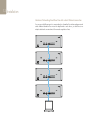
Hardware: Networking SmartView Duo with a direct Ethernet connection
You can connect the Ethernet port of a computer directly to a SmartView Duo without needing a network
switch. Additional SmartView Duo units can be daisy-chained to each other so you don't have to run
multiple cables back to a network switch. Power must be supplied to all units.
14 Installation
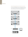
Hardware: Networking SmartView Duo with an Ethernet network switch
If you want to connect several SmartView Duo units to your studio's existing network, you only need to
connect one SmartView Duo to the network switch. The rest can be daisy-chained to each other so you
don't have to run multiple cables back to a network switch. Power must be supplied to all units.
Ethernet
Network Switch
Client
Computers
15 Installation
5
4
3
2
1
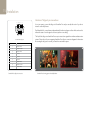
Hardware: Tally port pin connections
It is not necessary to connect the tally port of SmartView Duo and you can skip this section if you do not
intend to use the tally feature.
Each SmartView Duo screen features independent tally borders in red, green or blue which can be used to
indicate the status of a video signal such as on-air, preview or recording.
9
8
7
6
SmartView Duo tally port
Pin
The 9-pin D-sub tally port on SmartView Duo accepts contact closure signals from switchers and automation
systems. Please refer to the accompanying SmartView Duo tally pin connections diagram for information
about wiring the tally port for use with your switcher or automation system.
Function
1
Monitor 1 Red
2
Monitor 1 Green
3
Monitor 1 Blue
4
Ground
5
Ground
6
Ground
7
Monitor 2 Red
8
Monitor 2 Green
9
Monitor 2 Blue
SmartView Duo tally pin connections.
SmartView Duo showing green and red tally borders
16 Installation
Software: Installing the Blackmagic SmartView Utility software
It is not necessary to install any software in order to view SDI video and you can skip this section if you simply
want to view video without making any adjustments. However if you wish to adjust the network or monitor
settings, you will need to install the Blackmagic SmartView Utility software.
The Blackmagic SmartView Utility software runs on the latest Snow Leopard version of Mac
OS X. On the Windows platform, Videohub software runs on both 32 and 64-bit versions of
Windows XP, Windows Vista and Windows 7 with the latest service packs installed. Testing on previous
versions of these operating systems is not conducted and so it is always best to keep up to date with the
latest versions of Mac OS X and Windows.
The Blackmagic SmartView Utility software only needs to be installed on one computer but can be installed
on multiple, networked computers if desired.
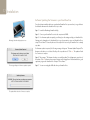
Mac OS X installation: Drag the Blackmagic SmartView
Utility to the Applications folder
While the CD supplied with SmartView Duo contains the software installer, we recommend
you visit www.blackmagic-design.com to ensure you have the latest version.
On Mac OS X, open the supplied CD, or downloaded disk image, and drag the Blackmagic SmartView
Utility to your Applications folder.
On Windows, open the supplied CD, or downloaded disk image, and double-click on the SmartView
installer. Follow the onscreen prompts to install the software.
Windows installation: Follow install prompts.
17 Installation
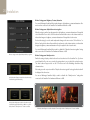
Software: Updating the firmware in your SmartView Duo
Once the software installation has been completed and SmartView Duo is powered on, it is a good idea to
check that the firmware in the SmartView Duo is up to date.
Blackmagic SmartView Utility application icon
Step 1.
Launch the Blackmagic SmartView Utility.
Step 2.
Connect your SmartView Duo unit to the computer via USB 2.0.
Step 3. If no firmware update is required, you will simply see the settings used by your SmartView Duo.
Settings can be changed now if desired and this is a good opportunity to give each SmartView Duo a
unique "Device Name". Please skip the rest of the steps in this section as your SmartView Duo is already
up to date.
If a firmware update is required, the following message will appear: "Firmware Update Required. The
firmware on this device is out of date. Would you like to update it now?" Click Yes. The update will take
4 or 5 minutes to complete.
Step 4. The message, "The firmware has been successfully updated," should appear at completion of
the update. Click OK to dismiss the message. Settings can be changed now if desired and this is a good
opportunity to give each SmartView Duo a unique "Device Name".
This message will appear if a firmware update is required.
The update will take about 4 or 5 minutes to complete.
Step 5.
You can now unplug the USB cable from your SmartView Duo.
18 Installation
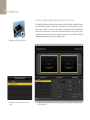
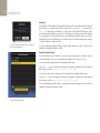
Software: Configuring Blackmagic SmartView Utility software
After installing the Blackmagic SmartView Utility software, launch the Blackmagic SmartView Utility and
it should immediately search your network for any SmartView Duo units by using the Bonjour service
discovery protocol. Any discovered units will be listed in the SmartView Monitors pane with an Ethernet
network icon next to their name. Select the name of the desired SmartView Duo and you will be able to
change the device name and also the monitor settings for each monitor on each SmartView Duo. Network
settings will remain grayed out and can only be changed via USB.
Blackmagic SmartView Utility application icon
SmartView Duo with an Ethernet network icon next to
its name.
The Blackmagic SmartView Utility automatically searches your network for any SmartView Duo units. Only one unit has
been found in this picture.
19 Installation
SmartView Duo with a USB icon next to its name.
If no SmartView monitors are found on the network, some units might not have received an IP address via
DHCP and it will be necessary to manually configure each unit with appropriate network settings. To do so,
connect a SmartView Duo to your computer via a standard USB 2.0 type A-B male cable and launch the
Blackmagic SmartView Utility. If the utility prompts you to update the firmware, refer to the previous section
named "Updating the firmware in your SmartView Duo". The USB-attached SmartView Duo unit will be
automatically selected in the SmartView Monitors pane and will show a USB icon next to its name. You will
be able to change all device name, network settings and monitor settings for the USB-attached unit.
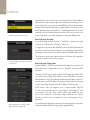
Network Settings pane: Device Name
It is a good idea to change the default "device name" of "SmartView Duo" so each unit is easy to identify
on a network, e.g. "Field Cameras 1&2", "HD edit suite", "2K feeds", etc.
To change the device name, select the desired SmartView Duo unit from the SmartView Monitors pane and
then edit its device name from the Network Settings pane. You can use Blackmagic SmartView Utility to
make changes to the device name when connected to the SmartView Duo hardware via Ethernet or USB.
The device name must not have a space character at the start or end of the name. If the software detects
an invalid device name, the text will turn red as you are typing.
The device name will turn red, if you type a space at the start
or end of the name.
Network Settings pane: Configure Address
By default, SmartView Duo uses DHCP to automatically obtain an IP address from your network. You will
probably want to leave the "Configure Address" option set to "Using DHCP" unless there is no DHCP
server present.
In the absence of a DHCP server, you may wish to enable the "Internet Sharing" feature of Mac OS X 10.6,
or the "Internet Connection Sharing" feature of Windows 7, to provide DHCP addresses to any directlyattached SmartView Duo units. This will avoid having to manually assign static IP addresses to each unit. You
can use this feature to provide DHCP addresses even though your computer might not have an Internet
connection. Internet sharing is described in the Mac OS X and Windows 7 Help documentation.
If DHCP cannot be used in your configuration, choose to configure the address "Using Static
IP". Please ask your system administrator for a spare IP address to avoid creating an IP conflict
on your network. You will need to specify a unique IP address for each SmartView Duo unit as
well as a common subnet mask. It is unnecessary to change the default value in the "Gateway"
field unless you intend to connect your SmartView Duo units to a network gateway, such as an
Internet router.
Network settings can be set to use DHCP or a Static IP
address and can only be changed via USB.
You can use Blackmagic SmartView Utility to make changes to the network settings when connected to the
SmartView Duo hardware via USB. Network settings cannot be changed via Ethernet.
20 Installation
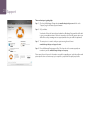
Monitor Settings pane: Brightness, Contrast, Saturation
You can use Blackmagic SmartView Utility to make changes to the brightness, contrast and saturation of the
monitors when connected to the SmartView Duo hardware via Ethernet or USB.
Monitor Settings pane: Adjust both monitors together
When this setting is enabled, any changes made to the brightness, contrast and saturation will be applied
to both SmartView Duo monitors. Yellow borders will surround both monitors in the software interface to
indicate that changes to brightness, contrast and saturation will be applied to both monitors.
Deselect this setting if you wish to make independent changes to the two monitors. Click on Monitor 1 or
Monitor 2 and a yellow border will surround the selected monitor, in the software interface, to indicate that
changes to brightness, contrast and saturation will only be applied to the selected monitor.
You can use Blackmagic SmartView Utility to enable or disable the "Adjust both monitors together" setting
when connected to the SmartView Duo hardware via Ethernet or USB.
Monitor settings can be adjusted independently or together
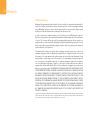
Monitor Settings pane: Identify monitor
Enable this setting to display a white border on the selected monitor of the SmartView Duo. If you have
several SmartView Duo units on a network, this setting makes it easy to identify the selected monitor.
The white border will appear both on the LCD monitor and in the Blackmagic SmartView Utility
software interface.
If this setting is used in conjunction with the "Adjust both monitors together" setting, the white border will
be displayed on both monitors.
A yellow border will appear around the selected monitor(s)
in the Blackmagic SmartView Utility.
You can use Blackmagic SmartView Utility to enable or disable the "Identify monitor" setting when
connected to the SmartView Duo hardware via Ethernet or USB.
A white border will appear around the selected monitor(s)
in the Blackmagic SmartView Utility, in addition to a yellow
border, when the "Identify monitor" feature is enabled.
A white border will appear around the selected LCD monitor(s) when the "Identify monitor" feature is enabled.
21 Installation
Add Device
If you already know the IP address of a SmartView Duo but it hasn't automatically appeared in the SmartView
Monitors pane, you can add the SmartView Duo manually. To do so, go to the Device menu and choose
Add Device or alternatively click Add Device (+) at the bottom of the SmartView Monitors pane. Type in
the IP address of the SmartView Duo and click OK. The software will verify the presence of the SmartView
Duo unit and add it to the SmartView Monitors list. If the Blackmagic SmartView Utility does not find a
SmartView Duo at the specified address, it will not add the unit to the list and will instead present a warning,
"A SmartView Monitor could not be found."
You can manually add a SmartView Duo, by IP address, to
the list of SmartView Monitors
You can use Blackmagic SmartView Utility to manually add a SmartView Duo when connected to the
SmartView Duo hardware via Ethernet or USB.
Copy/Paste Display Settings
If you have already set up one SmartView Duo unit with monitor settings that you would like to apply to
other SmartView Duo units, you can copy and paste the settings to those other units. To do so:
UÊÃiiVÌÊÌ
iÊ>Ài>`ÞÊVw}ÕÀi`ÊÕÌÊvÀÊÌ
iÊ->ÀÌ6iÜÊÌÀÃÊ«>i
UÊ}ÊÌÊÌ
iÊDevice menu, or alternatively click the action button (gear icon) at the bottom of the SmartView
Monitors pane, and choose Copy Display Settings (Ctrl-C, Cmd-C)
UÊÃiiVÌÊÌ
iÊÕÌ]ÊÜ
ÃiÊÌÀÊÃiÌÌ}ÃÊÞÕÊÜÃ
ÊÌÊV
>}i]ÊvÀÊÌ
iÊ->ÀÌ6iÜÊÌÀÃÊ«>i°
UÊ}ÊÌÊÌ
iÊDevice menu, or alternatively click the action button (gear icon) at the bottom of the SmartView
Monitors pane, and choose Paste Display Settings (Ctrl-V, Cmd-V)
You can use Blackmagic SmartView Utility to copy and paste the display settings when connected to the
SmartView Duo hardware via Ethernet or USB.
Copy and Paste Display Settings
22
Helpful Information
23 Support
There are four steps to getting help.
Step 1. Check out the Blackmagic Design web site www.blackmagic-design.com and click on the
“Support” page for the latest support information.
Step 2.
Call your dealer.
Your dealer will have the latest technical updates from Blackmagic Design and should be able
to give you immediate assistance. We also recommend you check out the support options your
dealer offers as they can arrange various support plans based on your workflow requirements.
Step 3.
The next option is to email us with your questions using the web form at
www.blackmagic-design.com/support/contact
Step 4.
Phone a Blackmagic Design support office. Check our web site for current support phone
numbers in your area. www.blackmagic-design.com/company.
Please provide us with as much information as possible regarding your technical problem and
system specifications so that we may try to respond to your problem as quickly as possible.
24
Warranty
25 Warranty
12 Month Warranty
Blackmagic Design warrants that this product will be free from defects in materials and workmanship for
a period of 12 months from the date of purchase. If a product proves to be defective during this warranty
period, Blackmagic Design, at its option, either will repair the defective product without charge for parts
and labor, or will provide a replacement in exchange for the defective product.
In order to obtain service under this warranty, you the Customer, must notify Blackmagic Design of the
defect before the expiration of the warranty period and make suitable arrangements for the performance
of service. The Customer shall be responsible for packaging and shipping the defective product to a
designated service center nominated by Blackmagic Design, with shipping charges pre paid. Customer
shall be responsible for paying all shipping changes, insurance, duties, taxes, and any other charges for
products returned to us for any reason.
This warranty shall not apply to any defect, failure or damage caused by improper use or improper or
inadequate maintenance and care. Blackmagic Design shall not be obligated to furnish service under
this warranty: a) to repair damage resulting from attempts by personal other than Blackmagic Design
representatives to install, repair or service the product, b) to repair damage resulting from improper
use or connection to incompatible equipment, c) to repair any damage or malfunction caused by the
use of non Blackmagic Design parts or supplies, or d) to service a product that has been modified or
integrated with other products when the effect of such a modification or integration increases the time or
difficulty of servicing the product. THIS WARRANTY IS GIVEN BY BLACKMAGIC DESIGN IN LIEU OF ANY
OTHER WARRANTIES, EXPRESS OR IMPLIED. BLACKMAGIC DESIGN AND ITS VENDORS DISCLAIM
ANY IMPLIED WARRANTIES OF MERCHANTABILITY OR FITNESS FOR A PARTICULAR PURPOSE.
BLACKMAGIC DESIGN’S RESPONSIBILITY TO REPAIR OR REPLACE DEFECTIVE PRODUCTS IS THE
WHOLE AND EXCLUSIVE REMEDY PROVIDED TO THE CUSTOMER FOR ANY INDIRECT, SPECIAL,
INCIDENTAL OR CONSEQUENTIAL DAMAGES IRRESPECTIVE OF WHETHER BLACKMAGIC DESIGN
OR THE VENDOR HAS ADVANCE NOTICE OF THE POSSIBILITY OF SUCH DAMAGES. BLACKMAGIC
DESIGN IS NOT LIABLE FOR ANY ILLEGAL USE OF EQUIPMENT BY CUSTOMER. BLACKMAGIC IS
NOT LIABLE FOR ANY DAMAGES RESULTING FROM USE OF THIS PRODUCT. USER OPERATES THIS
PRODUCT AT OWN RISK.
Copyright 2011 Blackmagic Design. All rights reserved. ‘Blackmagic Design’, ‘DeckLink’, ‘HDLink’, ‘Workgroup Videohub’, ‘ Videohub’, ‘DeckLink’,
‘Intensity’ and ‘Leading the creative video revolution’ are registered trademarks in the US and other countries. All other company and product
names may be trade marks of their respective companies with which they are associated.