1
ROBIN AMERICA, mc.
ROBIN TO WISCONSIN ROBIN
ENGINE MODEL CROSS REFERENCE LIST
ROBIN
EY08
EYl5
EY 15V
-
WISCONSIN ROBIN
EY20
EY2OV
EY23
EY28
EY35
EY40
EY45V
EY2 1
EY44
EY 18-3
EY25
EY27
EHl 1
W1-080
W1-145
W1-145V
w1-185
W1-185V
Wl-230
W 1-280
W1-340
W1-390
W1-450V
EY21W
EY44W
EY 18-3W
EY25W
EY27W
WOl-115
WOl-120
WO1-150
WO1-170
wo1-210
WO1-250
WO 1-300
WO 1 -300v
WO 1-340
WO 1 -340V
WO 1 -430V
EH12
EH15
EH17
EH21
EH25
EH30
EH3OV
EH34
EH34V
EH43V
TWO CYCLE
EC13V
WT1-125V
DY23
DY27
DY30
DY35
DY4 1
WRD 1-230
WRD 1-270
WRD 1-300
WRD1-350
wRDl-410
CONTENTS
Section
Title
.
Page
...........................................
1
...........................................
2
........................................
2-1
Maximum
Output
2-2
Continuous
Rated Output . . . . . . . . . . . . . . . . . . . . . . . . . . . . . . . . . .
2-3 MaximumTorque andFuel ConsumptionRatio a t Max . Output . . . . . . .
2
2
2
1 SPECIFICATIONS
2. PERFORMANCE
..
3 . FEATURES . . . . . . . . . . . . . . . . . . . . . . . . . . . . . . . . . . . . . . . . . . . . . . . .
4
4 . GENERALDESCRIPTION
4
of ENGINECONSTRUCTION
...............
4-1 Cylinder Crankcase . . . . . . . . . . . . . . . . . . . . . . . . . . . . . . . . . . . . . .
4-2 Main Bearing
Cover . . . . . . . . . . . . . . . . . . . . . . . . . . . . . . . . . . . . . . .
...........................................
4-3
Crankshaft
4.4 Connecting Rod
and
Piston
.................................
4-5 Camshaft . . . . . . . . . . . . . . . . . . . . . . . . . . . . . . . . . . . . . . . . . . . . .
4-6
Valve
Arrangement . . . . . . . . . . . . . . . . . . . . . . . . . . . . . . . . . . . . . . .
4-7 Cylinder Head . . . . . . . . . . . . . . . . . . . . . . . . . . . . . . . . . . . . . . . . . .
4-8 Governor . . . . . . . . . . . . . . . . . . . . . . . . . . . . . . . . . . . . . . . . . . . . .
4-9 Cooling . . . . . . . . . . . . . . . . . . . . . . . . . . . . . . . . . . . . . . . . . . . . . . .
4-10 Lubrication . . . . . . . . . . . . . . . . . . . . . . . . . . . . . . . . . . . . . . . . . . . .
4-11
Ignition
..............................................
4-12
Carburetor
............................................
4-13 Air Cleaner . . . . . . . . . . . . . . . . . . . . . . . . . . . . . . . . . . . . . . . . . . . .
4-14SectionalView
of Engine . . . . . . . . . . . . . . . . . . . . . . . . . . . . . . . . . . .
4
4
4
4
4
5
5.lNSTALLATlON . . . . . . . . . . . . . . . . . . . . . . . . . . . . . . . . . . . . . . . . . . . .
14
..............................................
5-1
Installing
5-2
Ventilation
............................................
5-3Exhaust
Gas Evacuation . . . . . . . . . . . . . . . . . . . . . . . . . . . . . . . . . . . .
5-4 Fuel System . . . . . . . . . . . . . . . . . . . . . . . . . . . . . . . . . . . . . . . . . . .
5-5 PowerTransmission to Driven Machines . . . . . . . . . . . . . . . . . . . . . . . . .
5-6 Wiring . . . . . . . . . . . . . . . . . . . . . . . . . . . . . . . . . . . . . . . . . . . . .
14
14
14
14
14
6. DISASSEMBLY and REASSEMBLY . . . . . . . . . . . . . . . . . . . . . . . . . . . . . .
21
6-1
6-2
6-3
Preparation and
Suggestions . . . . . . . . . . . . . . . . . . . . . . . . . . . . . . . . .
Special Tools . . . . . . . . . . . . . . . . . . . . . . . . . . . . . . . . . . . . . . . . . . .
Disassembly
and
Ressembly
Procedures
.........................
5
5
5
5
5
5
5
6
15
21
21
22
7.MAGNETO
7-1
7-2
7-3
74
................................................
29
Magneto . . . . . . . . . . . . . . . . . . . . . . . . . . . . . . . . . . . . . . . . . . . . .
Breaker PointAdjustment
..................................
Timing Adjustment . . . . . . . . . . . . . . . . . . . . . . . . . . . . . . . . . . . . . . .
Magneto TroubleShooting . . . . . . . . . . . . . . . . . . . . . . . . . . . . . . . . . . .
29
29
30
...................................
32
.............................................
33
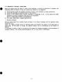
8 . GOVERNORADJUSTMENT
9. CARBURETOR
31
Operation and Construction . . . . . . . . . . . . . . . . . . . . . . . . . . . . . . . . .
33
Disassembly and Reassembly . . . . . . . . . . . . . . . . . . . . . . . . . . . . . . . . 34
9-3
Adjustment
. . . . . . . . . . . . . . . . . . . . . . . . . . . . . . . . . . . . . . . . . . . . 36
9-1
9-2
10. RUN-INOPERATION
11. TROUBLESHOOTtNG
of REASSEMBLEDENGINE
...................
.......................................
Starting Difficulties . . . . . . . . . . . . . . . . . . . . . . . . . . . . . . . . . . . . . . .
Engine Misses . . . . . . . . . . . . . . . . . . . . . . . . . . . . . . . . . . . . . . . . . . .
EngineStops . . . . . . . . . . . . . . . . . . . . . . . . . . . . . . . . . . . . . . . . . . .
EngineOverheats . . . . . . . . . . . . . . . . . . . . . . . . . . . . . . . . . . . . . . . .
11-5 Engine Knocks . . . . . . . . . . . . . . . . . . . . . . . . . . . . . . . . . . . . . . . . .
11-6 Engine BackfiresThroughCarburetor . . . . . . . . . . . . . . . . . . . . . . . . . . .
1 1 -1
11-2
11-3
114
12. CHECKS ANDCORRECTIONS
13. CORRECTIONTABLE
38
38
39
39
39
40
40
.................................
41
.......................................
42
14. MAINTENANCE and STORING
.................................
14-1Daily Checksand maintenance(Every 8 Hours) . . . . . . . . . . . . . . . . . . . .
14-2 Every 20 Hours ChecksandMaintenance
........................
14-3 Every 50 Hours (10 D a y ) ChecksandMaintenance . . . . . . . . . . . . . . . . . .
14-4 Every 100 200 Hours (Monthly) Checks and Maintenance . . . . . . . . . . . .
14-5 Every 500 600 Hours (Semianual) Checks and Maintenance . . . . . . . . . . .
14-6 Every 1000 Hours (Yearly) Checks and Maintenance . . . . . . . . . . . . . . . . .
14-7 Preparation forLong-Term Storage . . . . . . . . . . . . . . . . . . . . . . . . . . . .
.
.
37
48
48
48
48
48
49
49
49
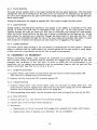
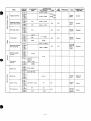
1. SPEC1FICATIONS
[
p
5
0
N
n
0
2
"
V
m
t1
c
t
I
I
i
-1
-
2. PERFORMANCE
2-1 MAXIMUM OUTPUT
n
The Maximum output of an engine is such standard power as developed by that engine, after its
initial run-in period with
all the moving parts properly worn-in, when operating with the fully
openthrottlevalve.Therefore,it
follows t h a t a newenginemaynotdevelopthismaximum
output in t h e beginning, because moving parts are not in a properly worn-in condition.
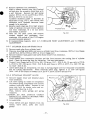
2-2 CONTINUOUSRATEDOUTPUT
Thecontinuous rated outputofanengine
is such powerasdeveloped
by t h a t enginewhen
running a t anoptimumspeedmostfavorablefromthepointofviewofenginelifeandfuel
a drivingsystemforany
consumptionratio.Therefore,itfollowsthatwhendesigning
mechanism, with a model EY14, EY18-3, EY23,
EY25-2 and EY27-2 engine, as a prime mover,
t h e continuous power requirement of t h a t mechanism must be kept below t h e continuous rated
output specified.
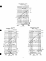
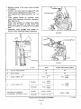
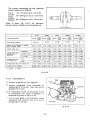
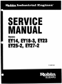
2-3 MAXIMUM TORQUE and FUELCONSUMPTIONRATIO
A T MAX.OUTPUT
The maximum torque of an engine is that driving torque of the driving shaft a t which the engine
is drivinganexternalload,
while the engine is developing its max.
output.
The
fuel
consumption ratio at max. output is t h a t fuel consumption ratio of an engine while t h a t engine
is running at t h e rnax. output.
PERFORMANCECURVE
MODELEY18-38
PERFORMANCECURVE
-2-
7
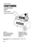
PERFORMANCE CURVE
MODEL EY23
( ) for B type
1.5(3.0)
1.0 (2.0)
6
I
kg-m
5
HP
I 4
I
3
g1HP.h
350
300
2
250
3000
2000
(1000)
rpm
( 1500)
4000
(2000)
__c
PERFORMANCECURVE
MODELEY27-2
( ) f o r 8 type
PERFORMANCECURVE
MODELEY25-2
( ) for
B type
1.4(2.8)
1.3(2.6)
I
7
kg-m
6
5
HP
I4
I
3
g1HP.h
340
.h
2
320
2500
(1250)
3000
(1500)
rpm
-3 -
-
3500
(1750)
4000
(2000)
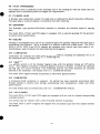
FEATURES
A compact,lightweightanddurable4-cycleair-cooledenginewithhighpoweroutput,
embodying
ingenious
design
technique
advanced
and
production
skill.
n
Simple construction, smart appearance, easystart.
Reliable power for wide. variety of purposes, with smooth speed controll by
under varying load conditions.
Economical advantage throughlow fuel consumption.
a governor,
Great versatility in installation through a 360° belt extension possibility and a two side oil
fill and drain arrangement.
GENERALDESCRIPTJON
of ENGINECONSTRUCTION
CYLINDER,CRANKCASE
The cylinder and t h e crankcase are die-cast as a compact aluminium mono-block piece. The
cylinder liner and t h e valve seats are made of special alloy cast iron and are imbedded in t h e
are located a t oneside
of t h e
The crankcase is separable at the driving shaft side and this separable piece constitutes
main bearing cover.
the
aluminiumcasting as inserts.Theintakeandexhaustports
cylinder and are also made of inserted pieces in t h e casting.
4-2 MAINBEARING
COVER
As the aluminium die-cast main bearing cover
is built onto the crankcase on the driving shaft
side,theengine'inside
are reached forinspection,easilybysimplyremovingit.It
is also
provided with a flange and boss for directly mounting operating machines such
as g e n e r a t o r s
and pumps.
There are two oil filters serving alsoas oil gauges provided at two locations.
(However, in EY18-3 or EY23 engine, at one location in t h e carburetor side.)
4-3 CRANKSHAFT
The crankshaft is machined from
a carbon steel forging with an induction hardened crank pin.
On t h e fan side, the breaker cam is provided and on
t h e driving side, t h e crankshaft gear is
force-fit.
4 4 CONNECTINGROD
and PISTON
The connecting rod is machined from an aluminium alloy forging in which the forged alloy itself
serves as t h e bearing metal a t both ends.On
the large end, an oil scraper
for splashing t h e
lubricating oil is provided.
The piston is machined from an aluminium alloy casting and
compression rings and one groovefor the oil ring.
is provided with two grooves
for
4-5 CAMSHAFT
The camshaft is machined from
a carbon steel forging with integral intake and exhaust cams
and is provided with a force-fit cam gear. In t h e model B engine, t h e camshaft s e r v e s also as
t h e driving shaft, being driven
at half t h e crankshaft speed. In the EY14D,EY23D,EY25-2D
and EY27-2D engines, t h e c a m s h a f t is machined from a special alloy cast iron with an integral
camshaft gear, andissupported
by aluminiumbearingmetalsmachinedintegralwith
the
crankcase at both ends. (no ball bearing is used)
-4 -
n
4-6 VALVEARRANGEMENT
The exhaust valve is positioned in t h e upstream side of the cooling
- air with the result that the
exhaust valve is intensively cooled for engine life improvement.
4-7 CYLINDER HEAD
A Ricardo type combustion chamber of ample area is employed for good combustion efficiency.
The spark plug is mounted obliquely to facilitate fuel tank mounting.
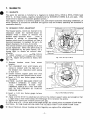
4-8 GOVERNOR
The flyweight type governor effectively operates to maintain the selected speed a t varying
load.
The model EY14, EY18-3 and EY23 engine is equipped with a separate gearing for the governor
t o secure better performance.
4-9 COOLING
Cooling is accomplished by a flow of air circulated past the cylinder walls and head fins from a
combination fan-flywheel. The air is guided by a cylinder buffle and a head cover. The EY14,
EY18-3, EY23, EY25-2 and EY27-2 engines are equipped with curved vane fans made in two
modifications, each for direct drive and reduction drive engines.
4-10 LUBRICATION
Lubrication for rotating and sliding parts is accomplished by scooping and splashing
the crankcase with oil scraper attached to connecting rod.
the oil in
4-11
IGNITION
The ignition system is of the flywheel magneto type with the ignition timing set 230 before
T.D.C.The magneto comprises a flywheel, ignition coil and a breaker, of which the flywheel
(serving also as a fan) is mounted on the crankshaft and the two other members are mounted
directly in the crankcase. (for details, refer to 7. MAGNETO section)
The model EY23 engine normally incorporates an electronic ignition system.
4-12
CARBURETOR
A horizontal draftcarburetor is employed. Itssetting has been carefullydetermined after
through testingto achieve best starting,accelerating,fuel
consumption, output and other
performances.
For other details such as construction, refer to 9. CARBURETOR section.
4-13 AIR CLEANER
The model EY 14, EY18-3 and EY23 engines are equipped with an oval air cleaner incorporating
8 sponge element.
The cycl.one type air cleaner with a semi-wet double element is optional.
T h e model EY25-2, EY27-2 engines are equipped with an cyclone type semi-wet double element
air cleaner.
-5-
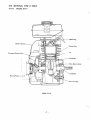
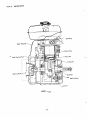
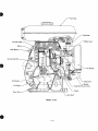
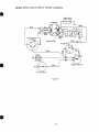
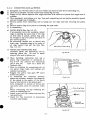
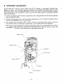
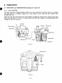
4-14 SECTIONAL VIEW of ENGINE
4-14-1
MODEL EY14
Blower Housing
FIywheel (Cooling
ver
Starting Pulley-
MODEL EY14
-6-
Fuel Tank
MODEL EY14
-7
-
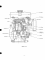
4-14-2
MODEL EY18-3
Cover
MODEL EY18-3
-a-
/-
/
MODEL EY18-3
-9-
Tank
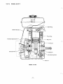
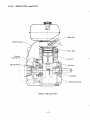
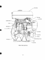
4-14-3
MODEL EY23
Flywheel
Star
7g
MODEL EY23
- 10 -
Cover
/"
Tank
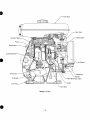
Con
Cam Shaft
MODEL EY23
- 11 -
4-14-4
MODEL EY25-2 and EY27-2
Cover
MODEL EY25-2 and EY27-2
- 12 -
I
I ti
I
\Cam
MODEL EY25-2 and EY27-2
- 13 -
Shaft
5. INSTALLATION
The life, ease of maintenance, frequency of check and repair, and operating cost are g r e a t l y
affected by the way the engine is installed. When installing the engine, therefore, the following
contents must be studied carefully.
n
5-1 INSTALLING
When installingtheengine, its position,couplingconditionswiththeoperatingmachineand
anchoring or supporting method must be carefully studied.
be given to f a c i l i t a t e its
Especially, when deciding the installing position, consideration must
routines such as filing and checking of gasoline and oil, checking of spark plug and breaker,
maintenance of air cleaner and oil draining.
5-2 VENTILATION
The engine must be supplied with fresh air for cooling and fuel combustion. When the engine is
to be operated in a cover or in a small room, a proper means must be provided for cooling air
re-circulation or ducts and baffle plates for guiding a cooling air, because if t h e t e m p e r a t u r e in
is allowed to rise,vaporlock,oildeterioration,increaseof
oil
theenginecompartment
consumption,powerreduction,seizure,
loss of enginelife or other troubles are caused,and
proper operation is harmed. The temperature of the engine compartment must be maintained
below 50OC even in summer with necessary ventilation arrangement.
5-3 EXHAUST GAS EVACUATION
Since t h e exhaust gas from t h e engine is toxic, when t h e engine is operated indoors, the exhaust
gas must be evacuated to outside.Sincetheoutputpower
of anengine
is considerably
influenced by t h e length of the exhaust duct, its diameter must be increased in proportion to its
length.
5-4 FUEL SYSTEM
When t h e standard fuel tank is installed separate from t h e engine, it must be so located t h a t its
bottom surface lies withint h e height of 5 CL 50 cm from the fuel joint of the carburetor.
When t h e fuel tank is installed too low, fuel is not fed properly and
t h e carburetor overflow is caused.
When connecting t h e fuelpipe,
to eliminateairlockandvapor
carefully examined for heat conductivity, diameter, bending, and
standard I.D. of the fuel pipe is 4 ‘L 5 mm.
if it is positioned too high,
lock, t h e pipingmust
be
leakage through fittings. The
5-5 POWER TRANSMISSION to DRIVEN MACHINES
5-5-1 BELT DRIVE
Take t h e following notes into condition:-
o V-belts a r e p r e f e r r e d t o flat belts.
o The driving shaft of t h e engine and t h e driven shaft of t h e driven machine must be parallel.
o The driving pulley of t h e engine and t h e driven pulley of t h e driven machine must be aligned
correctly.
o The driving pulley must be mounted as near t h e engine as possible.
o As far as possible, t h e belt is spanned horizontally.
o When starting the engine, t h e load must be disconnected from t h e engine.
o If a clutch is not available, a tension pulley or other means must be employed.
- 14
-
F-,
5-5-2
FLEXIBLECOUPLING
When a flexible coupling is used, t h e runout and mis-alignment between t h e driven shaft and t h e
engine driving shaft must be made as s m a l l as possible.
The tolerances on t h e runout and mis-alignment are specified by each coupling maker.
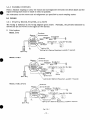
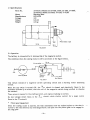
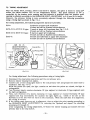
5-6 WIRING
5-6-1
START by RECOIL STARTER, or by ROPE
The wiring is indicated in the wiring diagram given below. Normally,
dotted line are not wired in the engine at the factory.
the portions indicated by
1) Pointsystem
MODEL EY14
~
Stoo Button
Lighting Switch
Lamp (6V-8V ',15W)
\ 'Ignition Coil
Lighting Coil (Optional Equipment, available if required)
Spark Plug
MODEL EY18-3
Contact Breaker
la"
"-7
'
Lighting Coil (Optional Equipment, available if required)
EY27-2
EY25-2,
MODEL
,Condenser
ir.ed )
Fig. 5-67
- 15 -
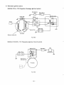
2) Electronic ignition system
MODEL EY14: CDI (Capacitor Discharge Ignition) system
Stop Button
BlackMlhite
Pulser Coil
""".J
Optional Lamp Coil
Fig. 58-2
MODEL EY23 STD: TIC (Transistor Ignition Circuit) system
Connector
CoilIgnition
i
Spark Plug
Stop Button
"
L
m7
Fig. 5-6-3
- 16 -
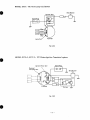
MODEL EY23: TIC with Lamp Coil System
Stop Button
Ignition Coil
Spark Plug
77!7
Lamp Coil /
Flywheel
Fig. 5-64
MODEL EY25-2, EY27-2:
PIT (Pulser Ignition Transistor) system
Ignition Pulser C o i l
\
Spark
Plug
I
Optional
Lamp C o i l etc.
1
Stop Button
Flywheel
Fig. 5-6-5
- 17 -
.
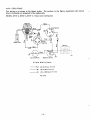
CELL START
as showninthefigurebelow.Thesection,inthefigure,describedwithdotted
Thewiringis
lines is normally not prepared in the engine side.
MODEL EY18-3, EY25-2, EY27-2:
Point with Cell System
5-6-2
Black
Magneto
Spark Plug
a
Black
Starting Motor
Magnetic
Switch
-
7777
EY18-3D, BS Wiring Diagram
JIS CB Female Terminal
JIS CA MaleTerminal
8
JIS LA106 Board Terminal
- 18
-
,~
MODEL EY23, EY25-2, EY27-2: PIT with Cell System
Spark plug
Flywheel
i
Magnetic Switch
Starting Motor
F&. 5-6-7
-19-
1) Specifications
P a r t s No.
Name
Manufacturer
Voltage
Output
Weight
14
2147050110 (Model EY18-3BS, 23BS, 25-2BS, 27-2BS),
2147050210 (Model EY23DS, 25-2DS, 2 7-2DS)
Starting Motor
HITACHI
12v
0.6 kW
131.5
-
31.5
F&. 5-6-8
2) Operation
The battery is connected to t h e t e r m i n a l 66 of the magnetic switch.
The condition when the starting motor is ON is as shown in the figure below.
iM
t
“ S
;.
tM
Starting Motor
Switch
Fig. 5-6-9
Thiscircuitconsists
circuit.
Ijl
4
Key Switch
of a magnetic s w i t c h operatingcircuitand
-
a startingmotoroperating
M
When the key switch is turned ON, the
circuitisclosed,andelectricity
direction directed by an arrow, thus the coil of the magnetic switch being excited
the contact.
flows to the
to absorbe
Then, power is supplied to t h e starting motor, and engine cranking is started.
so, low voltage current flows in t h e M circuit,while starter current for a large current
flows in t h e S
circuit.
*
Pinion gear engagement
When t h e starting motor is s t a r t e d , t h e wait assembled w i t h t h e helical spline on t h e shaft is
moved to t h e axial direction by centrifugal force, and push out the pinion gear t o be engaged in
t h e ring gear.
-20 -
T-”.
6. DISASSEMBLY and REASSEMBLY
0
6-1 PREPARATION and SUGGESTIONS
1) When disassembling the engine, memorize the locations of individual parts so as to be able
to reassemble them correctly. Tag parts if there is a possibility of confusion.
t o keep parts beginning to certain groups together.
Group those partsrelatedeachother,tentatively
assembling where they belong, immediately after removing, in order to prevent missing and misplacing.
Handle the disassembled parts carefully and wash them in kerosene.
Use the correct tools in the correct way.
Standard tools required for disassembling and reassembling:
'2) Prepare several boxes
3)
4)
5)
6)
a) Work table
b) Washingpan
c ) Disassembling tools
d ) Washing oil (kerosene or gasoline), Mobile oil
e) Emery paper, cloth
7) Before starting to disassemble the engine, drain fuel and lubricant. Oil can be drained
when the oil drain plug on the crankcase side wall on the carburetor side is unscrewed.
8) Tighten the screws of the cylinder head, main bearing cover, connecting rod, spark plug,
and flywheel to the specified torque values.
9 ) Usenew packings and gaskets in reassembly.
10) Immedaitely before assembling parts, wash them in fresh gasoline or kerosene andblow
0
them dry.
11) ApplyMobile
oil on rotating and sliding parts.
1 2 ) Take care not to contaminate the parts by dust during assembling.
13) Tighten bolts, nuts and screws with proper torque according to thetheirsizes.
screws are tightened too tight, they may get broken.
14) After completely assembling the engine, turn it by hand
and
abnormality or loose members.
check if there is any
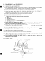
6-2 SPECIAL TOOLS
Flywheel Puller
Valve Guide Puller
Valve Seat Cutter
Valve Spring Compressor
Fig. 6-2
-21 -
If small
Part No.
QtY
FlywheelPuller
209 95004 07
1
Bolt
001 6608500
3
Valve Spring Compressor
2079500307
1
Description
1
Remarks
EY14, EY18-3, EY23, EY25-2, EY27-2
I
95001
I
Valve Guide Puller
(Plate, Shaft, Nut)
Valve Seat Cutter
205
I
07
I
1
206 95001 07 EY 18-3,1
EY14, EY18-3, EY23, EY25-2, EY27-2
I
I
I
EY 14
EY 23
207 95001 07
1
EY25-2, EY27-2
2079500207
1
EY14, EY18-3, EY23, EY25-2, EY27-2
6-3 DISASSEMBLY and REASSEMBLY PROCEDURES
6-3-1
FUEL TANK and FUEL TANK BRACKET
1) Disconnect fuel pipe between strainer and carburetor at carburetor side.
2) Remove fuel tank from bracket. ( 8 m m nut, 4 pieces) (EY14:3 pieces)
3) Remove tank bracket from cylinder head (EY14: 8 mmflangenut/EY18-3,EY23,
EY25-2,
EY27-2: 10 mm flange nut, 4 pieces)
6-3-2
BLOWERHOUSING and HEADCOVER
1) Remove blower housing from crankcase and head cover (cylinder baffle).
(EY14: 6 x 8 mm Flange bolt,
bolt, 6 pieces)
nder
from
. (cylinder
baffle)
cover
2) head
Remove
6-3-3
6 pieces/EY18-3, EY23, EY25-2, EY27-2: 6 x 12 mm Flange
-
AIRCLEANER
1) Remove air cleaner cover and element.
2) Loosen two bolts and remove air cleaner case from carburetor. (EY14: 6 x 8 mm Flange bolt
2 pieces/EY18-3, EY23, EY25-2, EY27-2: 6 x 10 mm bolts, 2' pieces) (EY25-2, EY27-2: a t t h e
s a m e time, disconnect choke knob that is connected to carburetor choke lever.)
3) Disconnect breather pipe.
4) In reassembly, wash element in kerosene shaking well until
dirt is sufficiently removed. Dry
element thoroughly and apply mixture'of 4 part kerosene and 1 p a r t Mobile oil. Squeeze out
excess oil before reinstallingit.
6-3-4
MUFFLER
Remove muffler from cylinder part of crankcase. (EY14, EY18-3, EY23,
nut, 2 pieces)
6-3-5
EY25-2, EY27-2:
8 mm
GOVERNOR LEVER and CARBURETOR
1) Remove governor lever from governor shaft. (6 mm bolt, 1 pieces)
2) Remove governor rod and rod spring from carburetor.
3) Remove carburetor from cylinder part of crankcase. (6mm nut, 2 pieces)
In reassembly, refer to 8. GOVERNOR ADJUSTMENT section.
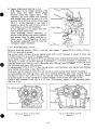
6-3-6
STARTINGPULLEYandMAGNETO
1) Removestartingpulleyfromflywheel.
(EY14: 6 x 1 2 mmbolt/EY25-2,
bolt, 3 pieces)
- 22 -
EY27-2: 8 x 12 mm
-
0
2) Remove flywheel from crankshaft.
Apply a socket wrench over the flywheel
nut and give the wrench a sharp blow with
a softhammer.Removenutandspring
washer. (EY14: 1 2 mm nut/EY18-3, EY23,
EY25-2, EY27-2: 14 mm nut)
to flywheel as
Attachedflywheelpuller
illustratedinFig.
6-3-1, t u r n c e n t e r bolt
clockwiseuntilflywheelbecomes
loose
enough to be removed.
3) Remove spark plug cap from high tension
cable of ignition coil and remove ignition
Flywheel Puller
Flywheel
(6 x 25 mmscrew
coilfromcrankcase.
and washer, 2 pieces)
Fig. 6-37
off
the
point
cover
and
remove
4) Take
contact
breaker
and
condenser,
from
crankcase (All models of the EY23 engine
are electronicallv ignited.)
7-3 TIMING
5) In reasseambling magneto, refer to 7-2 BREAKERPOINTADJUSTMENT,and
ADJUSTMENT.
I
"
6-3-7 CYLINDER HEAD and SPARK PLUG
1) Remove spark plug from cylinder head.
2) Unscrew mounting nuts/bolts and remove cylinder head from crankcase. (EY14:
8 mm flange
bolt/EY18-3, EY23, EY25-2, EY27-2: 10 mm flange nut)
3) Remove cylinder head gasket and baffle (head cover) from crankcase.
4) In reassembly;
* Clean carbon from combustion chamber and dirt from between the cooling fins
of cylinder
head. Check its mounting face for distortion. Use new head gasket.
* Torque 8 mm flange bolt in EY14 to 190 2.20 kg-cm (13.7.> 16.6 ft-lb), 1 0 rnm nuts in EY183, EY23 t o 330 % 360 kg-cm (23.8% 25.9 ft-lb), and those in EY25-2, EY27-2
to 340 % 370 kgc m (24.6 -26.8 ft-lb).
* Leave spark plug out temporarily, for ease in turning engine over for remainder of assembly
and for timingadjustments.
When mountingsparkplug,tighten
it t o 230 Q
270
,kg-cm
(16.6 %19.5 ft-lb) torque in models EY14, EY18-3, EY23, EY25-2 and EY27-2.
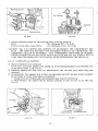
6-3-8 INTAKE and EXHAUST VALVES
1) Removetappetcoverandbreatherplate
from crankcase.
2) Lift valve spring by means of compressor
tool (valve spring compressor) and remove
Proceed in t h e
retainer locks and valves.
samewayboth
for intakevalveandexhaust valve. (See Fig. 6-3-2)
Then,removevalvespringsandspring
retainers.
DAMAGE
GASKET
CAUTION: DO NOT
SURFACE OF TAPPETCHAMBER WITH
THE COMPRESSOR TOOL.
3) In reassembly;
* Cleancarbonandgumdepositsfromthe
I
- 23 -
Fig. 6-3-2
Replace valves if the valve face is pitted
or warped.
Correct t h e valve seat by using 4S0 seat
c u t t e r tool as illustrated in Fig. 6-3-3.
The finished seat width should be 1.2 ~ 1 . 5
mrn.
Valve
guides
should
be replaced
when
valve stem clearance becomes excessive.
(See Fig. 6 - 3 4 )
Drawvalveguidesoutusing-valveguide
puller tool as shown in Fig. 6-3-4 and
press new guides in, using the same puller
tool.
Assemble
valve
springs
and
spring
retainers after adjusting tappet clearance.
Valve Seat Cutter
Fig. 6-3-3
t3"1
Guide
Fig. 6-3-4
A
-
EY18-3,
EY14
): EY14
(
45O
VALVE FACE ANGLE
45"
B - SEATANGLE
/
C - GUIDE INSIDE DIA.
6 dia.
INTAKE
0
I
I
45O
45O
7 dia.
-0.025
-0.040
.7 dia.
EXHAUST
i
D
I
INTAKE
EXHAUST
N.036
N.016
i
6 dia.
D - VALVE STEM DIA.
MAXIMUMALLOWABLE
CLEARANCE BETWEEN Cand
+0.015
E23, EY25-2,
EY27-2
6 dia.
-0.075
-0.095
-0.040
-0.062
0.025L- 0.055L
0.056L- 0.098L
0.075L- 0.1 1OL
VALVE and VALVE GUIDE CLEARANCE
Fig. 6-3-5
- 24 -
L: Loose
4) Tappet Adjustment (SeeFig. 6-3-6)
With tappet in its lowest position, hole
valve down and insert
feeler
gauge
between valve
and
tappet
stem.
The
clearance for both intake and exhaust,
with engine cold, must beand 0.16 % 0.20
m m for EY14, EY18-3, EY23, EY25-2 and
EY27-2. If theclearance is less than it
should be, grind the end of valve stem a
very little at a time and remeasure.
If theclearance is too large, sink valve
seat with seat cutter tool.
After obtaining correct
clearance,
assemble valve springs and spring retainers,
and secure them in place with the retainer locks. Check operation of valves
by turning crankshaft over by handand
remeasure tappet clearance.
6-3-9
Fig.
MAIN BEARINGCOVER
6-3-6
Removemounting
screws. (EY14: 6 m m bolt andwasher
7 pieces/EY18-3, EY23,EY25-2,
EY27-2: 8 m m bolt 8 pieces)
Taparound outersurface of main bearing cover with asoft hammer to break it loose and
carefully remove it, so as not to damage oil seal.
In reassembling EY14, EY18-3 and E Y 2 3 main bearing cover, install governor gear and governor
sleeve inside it first, andmake sure that governor shaft is already installed in crankcase. In
thiscase, in order to prevent damage of governor gear (made of plastics) whichhasbeen
installed insidemain bearing cover, reassemble main bearing cover to crankcase, making sure
that governor gear mesh with cam gear.
In reassembling EY25-2, EY27-2 main bearing cover, mount governor yoke inside main bearing
cover before remounting it. (See Fig. 6-3-7)
If oil seal must be replaced, force fit a new oil seal in main bearing cover before mounting it.
In reassembling main bearing cover, apply oil to bearing surfaces, gear train, tappets
and oil
seal lips and form a light film of oil on main bearing cover face to hold gasket in place. Mount
an oil seal guide on to the crankshaft to prevent damage to the oil.seallips. (Fig. 6-3-8)
Confirm that crankshaft endplay is 0 ~ 0 . 2 mm. If necessary, adjust it with adjusting collar.
(See Fig. 6-3-9)
Fig. 6-3-7B (E Y25-2, E Y27-21
Fig. 6-3-7A (EY14, EY18-3, EY231
(Model Bl
(Model D)
- 25 -
Adjusting Collar
Fig. 6-3-8
*
Fig.
6-3-9
Correct fastening torque for main bearing cover mounting screws is:
EY 14
80 %lo0 kg-cm (5.7%7.2 ft-lb)
EY18-3, EY23, EY25-2 and EY27-2
(12.2 13.7 ft-lb)
170 ~ 1 9 kg-cm
0
Q
CAUTION:
Fig.
6-3-9 SHOWS ONEMETHOD
OF MEASURING
THECRANKSHAFTEND
PLAY. THEDISTANCE
BETWEEN THEMACHINEDSURFACE
OF CRANKCASEAND
OF BEARING
ADJUSTING
COLLAR
IS MEASURE’D. THE
COMPRESSED
THICKNESS
COVER PACKINGIS 0.25 m m (EY14,EY18-3andEY23)and
0.15 m m (EY25-2,EY27-2)
TAKE THIS THICKNESS INTO CALCULATION WHEN DETERMINING THE END PLAY.
6-3-10
CAMSHAFTandTAPPETS
from
1) Remove camshaft
In this ease, to prevent tappets from falling out and becoming damaged, turn crankcase over
on its side as shown in Fig. 6-3-10.
2) Withdrawtappetsand
mark them for identificationwiththehole
from whichtheywere
removed.
3) In reassembly; *put tappets back in their corresponding hole first and then mount camshaft.
Do not forget t o mount thrust sleeve on camshaft.
* Timing marks on camshaft gear and crankshaft gear must be matched up.
If valvetiming is off, engine will notfunctionproperly
or maynot run at all. (See Fig.
6-3-1 1)
I
Fig. 6-311
F 3 . 6-370
- 26
-
,
6-3-11
CONNECTING ROD and PISTON
1) Straighten out t h e bent tabs of rod lock washer and remove bolts from connecting rod.
2) Take off oil scraper, rod lock washer and connecting rod cap..
3) Scrape off all carbon deposits t h a t might interfere with removal of piston from upper end of
4)
5)
6)
7)
cylinder.
Turn crankshaft until piston is at top, then push connecting rod and piston assembly upward
and out through top of cylinder.
Remove piston from connecting rod by taking out
two clips and then removing
t h e piston
pin.
Remove piston rings from piston by widening t h e open ends.
In reassembly;
a) PISTON RINGS (See Fig. 6-3-12)
If an expander tool is not available, install
rings by placing the open ends of t h e ring
onfirstland
of piston,spreadringonly
far enough to slip over piston and carry it
into correct groove.
Be extremelycarefulnot
to distortand
brake ring. Assemble rings in the order o f
oil ring,secondringandtopring.(See
Fig. 6-3-13)
b) PISTON and CONNECTING ROD
Assemblepistonandconnectingrod
by
insertingpiston
pin.
Be
sure to insert
clips at both ends of piston pin.
When installing
connecting
rod,
use
a
pistonringcompressor
as illustrated in
Fig. 6-3-14 andposition
t h e connecting
rod so t h a t t h e
mark on it faces t h e
flywheel side.
Prior to installing the connecting rod, oil
thepistonrings,largeendbearingand
cylinder wall amply.
Staggerthepistonringgaps
900 a p a r t
around t h e piston.
To .determine t h e clearance
between
piston and cylinder, measure the diameter
of the piston in t h e c e n t e r of the thrust
f a c e s at the bottom of the piston skirt.
Turn crankshaft to bottom of stroke and
tap piston down until rod contacts crank
pin.
the
Mountconnectingrodcapmatching
marks on connecting rod.
* Install a new rod lock washer and bend the
tabs positively.
* Check for free movement of connecting
rod after assembling.
Fa. 6-312
...
...
...
.......
.......
.......
.......
!"&
Oil Ring
.......
I
/ I
F is. 6-313
Piston Ring Guide
Fig. 6-314
- 27 -
Second Ring
The correct connecting rod capfastening
torque values are as follows:
EY 14
90 % 115 kg-cm (6.5 % 8.3 ft-lb)
EY18-3 170 % 200 kg-cm (12.3
EY 23
EY25-2 200 % 25Okg-m
EY 27-2
(14.4
%
%
14.4 ft-lb)
18.0 ft-lb)
Refer to c h a r t Fig. 6-3-15 for clearance
between piston, cylinder and connecting rod.
I f
J
I
I
I
EY 18-3
EY14
W
EY
EY27-2
23
L
I
EY25-2
D (crankshaft pin Dial
I
I
~
~
&
~
N
$
~ AT
> PISToN
! ~ ~ ~ 10.037L-0.075L
~ R
1
PISTON RING GAP
TOP RING
PISTON RINGSiDE
CLEARANCEIN
GROOVES
OIL RING
CONNECTING R O D
TO CRANKPIN
0.20L-0.40L
0.05L-0.095L
1
1
I
0.03L-0.069L
25
2.'
0.03L-0.069L
I
1
27
2.'
1
0.05L-0.095L
0.05L-O.OQ5L
0.05L-0.095L
0.04L-0.085LSECOND
RING
0.04L-0.085L.
0.04L-0.085L
0.04L-0.085L
0.04L-0.085L
0.01L-0.055L
0.01 L-0.065L
0.01 L-0.055L
0.01 L-0.055L
0.01 L-O.055L
0.037L-0.063L
SIDE
0.1L-0.3L
0.01 L-0.029L
0.1 L-0.3L
0.2L-0.7L
0.01L-0.029L
L-O.C29L
0.04L-0.066L
0.037L-0.063L
0.1 L-0.3L
0.1 L-0.3L
0.021 L-0.040L
0.021 L-0.04OL 0.01
I 0.004T-0.015L
I
T:
TIGHT
Fig. 6-375
6-3-12
CRANKSHAFT
1) Remove woodruff key (for magneto).
2) Remove
crankshaft
from
crankcase
tapping lightly at its end. Take
damage t h e oil seal.
2.'
0.06L-0.99L
~0.072L-O.111L
PISTON PIN TO PISTON
10.009T-0.01
)0.009T-O.01
L
10.009T-0.01
L
10.004T-0.015L
L
L: LOOSE,
27
I
I
o . o ~ L - o . ~ ~ 1L o . o ~ L - o . ~ ~ LI o . o ~ L - o . ~ ~ L1 o . o ~ L - o , ~ ~IL
0.05L-0.076L
CONNECTING ROD TO PISTON PIN
1
25 +0.1
23.4 kO.1
W (crankshaft pin Width)
by
care not to
3) In reassembly; Attach oil seal guide on end
of crankshaft
and
mount
crankshaft
in
crankcase as shown in Fig. 6-3-16.
* If a n oil seal guide is not available, mount
crankshaft w i t h e x t r e m e care so as not t o
damage lips of oil seal.
Crankshaft
I
Fig. 6-316
- 28 -
0.05L-0.095L
0.04L-0.066L
7. MAGNETO
7-1 MAGNETO
The spark for ignition
is furnished by a magneto in models EY14,
EY18-3, EY23, EY25-2 and
by KOKUSANDENKI K.K. are used. (The
EY27-2. In thesemodels,magnetosmanufactured
model EY23 is based on noncontact ignition system.)
The magneto consists of a flywheel, ignition coil, and breaker assembly (including condenser), of
which flywheel is mounted on crankshaft and ignition coil and breaker assembly are mounted in
crankcase directly.
7-2 BREAKERPOINTADJUSTMENT
The breaker points, which are mounted in the
crankcase
inside
the
flywheel
should
be
checked
twice
a season or wheneverthe
weak.
If there is
ignition spark becomes
evidence of pitting or pyramidding, the
breaker points must be corrected, and then it
becomes necessary t o readjust t h e g a p to i t s
proper clearance. (0.35 mm, 0.014 inch)
The normal breaker point opening is 0.35 mm
at full separation. Since t h e spark timing of
23O is regulated by the point opening, use a
timing light to o b t a i na na c c u r a t e
spark
advance.
To adjust breaker point
opening,
remove
startingpulley,blowerhousingandflywheel
from t h e engine and proceed as follows. (See
Fig. 7-2)
I
Fig. 7-2-A (EY74, EY18-31
1) Remove breaker cover from c o n t a c t
breaker.
2) Turncrankshaftoveruntil
breaker a r m
c o m e s in contactwith the high point of
the breaker cam. (maximum point opening
of 0.35 mm)
3) Loosencontactsupportplate
lock screw,
just enough so that bracket c a n be moved.
4)Insert
a 0.35 mmfeelergaugebetween
t h e points.
CAUTION:ADJUSTBREAKERPOINTGAP
WITHOUT
OPENING
IT MORE
THAN
2 m m , OTHERWISE
RATED
HEELPRESSING FORCE MAY NOT OBTAINED
DUE T O THE BENDING OFCONTACT
BREAKER ARM.
Fig. 7-2-6 (E Y25-2, E y27-21
5)Insert
a 0.35 mmfeelergaugebetween
the points.
6) Apply a screw driver to adjusting tab and move the contact support plate just enough so that
a slight drag is felt while sliding the feeler gauge from between t h e points.
7) Tighten lock screw and recheck breaker point gap.
8) Pull a s t r i p of 8 % l o rnm wide white paper through t h e closed points to remove oil and dust.
CAUTION: IN THIS CASE NEVER OPEN THE BREAKER POINT G A P MORE THAN 2 mm.
9) Mount flywheel, blower housing and starting pulley on engine after adjustment.
- 29 -
7-3 TIMING ADJUSTMENT
With the Model EY14,EY18-3,EY25-2
and EY27-2 engines, the spark is timed to occur 23O
before the pistonreachesTDCon
the compression stroke. Thissparkadvance
of 23O is
controlled by the breaker point opening and
this advance is obtained when the breaker point
opening is adjusted according to t h e BREAKER POINT ADJUSTMENT to 0.35 mm (0.014 inch).
However, the advancetiming is moreaccuratelyadjustedthrough
the followingprocedures,
using a timing light as shown in Fig. 7-3-1.
n
For timing adjustment, the following alignmentmarks are provided.
EY 14:
Projection atleft
upper
crankcase
M mark and slit on flywheel circumference
EY25-2 D & EY27-2 D type: D mark at lower left crankcase (see Fig. 7-3-2)
M mark and slit on flywheel circumference
EY25-2 B & EY27-2 B type: 3 mark at upper left crankcase
M mark and slit on flywheel circumference.
EY18-3:
M mark
relief
and
line
at upper
crankcase
left
M mark and slit on flywheel circumference
W
Flywheel
Fig. 7-3-2
Fig. 7-3-1
For timing adjustment, the following procedures using a timing light:
Disconnect the stop button lead wires and the coil primary wire.
Remove blower housing from engine.
Connect one of the timing light leads to the coil primary wire and ground the other lead t o
crankcase. (See Fig. 7-3-1)
While t h e points are open, the light remains on and when t h e points are closed, t h e light is
extinguished.
(D type engines) or clockwise !
I
3 type engines) until
Turn flywheel slowly counter-clockwise
the light extinguishes.
(D typeengines) or counter+lockwise (B type
Then,turnflywheelveryslowlyclockwise
t h e moment t h e lightlights up. Check if tine slit on t h e
engines)andstopimmediately
flywheel is in the line with t h e mark on t h e crankcase. When the mark line is in alignment,
t h e timing is cowect.
If t h e timing mark lines are not in alignment, then re-adjust the point opening according to
the BREAKER POINT ADJUSTMENT, by removing t h e flywheel and repeat
t h e checking
procedures 3) through 5 ) .
After completing the timing adjustment, re-mount t h e blower housing and connect t h e coil
primary lead to t h e stop button.
-30 -
/
1
7-4 MAGNETOTROUBLESHOOTING
When the engine does not start or starts with difficulty, or when its operation is unstable, the
following tests wiU clarify if they are caused by a defect in the magneto.
1) Check ignition cable for possible corrosion, broken, worn insulator or loose connection.
2) Check the sparking as described later in this section.
3) Check if the breaker points requirecleaning, or adjusting or not. If the points are badly
corroded or pitted. (Condenser may have t o be replaced.)
Refer to "BREAKER POINT ADJUSTMENT".
4) If no spark takes place, replace ignition coil.
*
SPARK TESTING
Remove spark plug from cylinder head and place it on blower housing, with the ignition cable
connected to it.
Crank the engine several times by starting pulleyand observe the spark in the spark gap of
spark plug. If the spark is strong,the ignition system can be eliminatedasthesource
of
trouble.
If the spark is weak or there is no spark at all, repeat the checks according to the procedures 1)
through 3) above. The correct electrode gap is 0.6 0.7 mm (0.024 % 0.028 inch).
Q
-31 -
8. GOVERNOR ADJUSTMENT
In the model EY 14, EY 18-3,EY23,EY25-2
and EY27-2 engines, acentrifugal flyweight type
governor is used.The
flyweight assembly is mounted on a separate governor gear in EY14,
EY18-3 and EY23 and on the camshaft gear in EY25-2 and EY27-2, and automatically regulate
the throttle valve of the carburetor in such a way that the engine speed is maintained constant
under varying loads.
1) Connect carburetor throttle lever and governor lever with governor rod and mount governor
lever on governor shaft.
2) Connect the governor lever and the rotation adjusting lever with a governor spring, and set
the rotation adjusting lever to the crankcase.
3) Turn control lever clockwise (EY14, EY18-3,EY23)
or counterclockwise (EY25-2,. EY 27-2)
until throttle valve in carburetor is opened fully. Lock control lever in this position.
4) With a screw driver inserted in the groove of govenor shaft, turn it clockwise (EY14, EY183, EY23) or counter-clockwise (EY25-2, EY27-2) fully (until it will not turn any more) and
then lock governor lever to governor shaft by tightening clamp bolt.
Governor Rod
\
Governor Spring
Fig. 8-1
- 32 -
1
’
1
9. CARBURETOR
9-1 OPERATION and CONSTRUCTION (See Figs. 9-1-1and 9-1-2)
9-1-1 FLOAT SYSTEM
The float chamber located directly beneath the main carburetor structure serves to maintain
at a constantheight by a jointaction of t h e float andtheneedlevalve
thefuellevel
incorporated in it.
Fuel from the fuel tank enters the float chamber through the needle valve, which is kept open
while the fuel level is low butis closed when t h e fuel level reaches a predetermined level
cousing the float to move up.
Throttle Valve
Pilot Outlet
I
F is. 9-7 -2
-33 -
9-1-2
PILOT SYSTEM
The pilot system supplies fuel to t h e engine during idle and low speed operation. The fuel taken
through t h e main jet is measured by t h e pilot jet t o mix with t h e air measured by the pilot air
jet and is then regulated by the pilot screw before being supplied to the engine through t h e pilot
o u t l e t and by-pass.
,-
During idle operation, the engine is supplied with fuel mainly through the pilot outlet.
9-1-3
MAIN SYSTEM
During medium and high-speed operation, fuel supply
to the engine is controlled in the main
system,inwhichfuelflow
rate is controlledbythemain
jet. In themainsystem,fuel
is
supplied through the main
jet where the flow rate is controlled, and through the main nozzle,
where the f u e l is mixed with air, the flow rate of which is controlled by the main air jet. In the
main nozzle the
metered a i r is admitted through the bleed holes
to mix with the fuel. The
mixture is then discharged through the top of the main nozzle as atomized fuel where it mixes
with intake air to become t h e optimum air-fuel mixture to be supplied to t h e engine.
9-1-4
CHOKE SYSTEM
The choke system aides starting in t h e cold season by enriching t h e air-fuel mixture. When t h e
engine is cranked with t h e choke closed, the vacuum applied to t h e main nozzle is made higher
so t h a t more fuel is introduced into t h e air flow to make a starting easy.
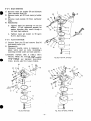
9-2 DISASSEMBLY and REASSEMBLY
Besidesmechanicalfailures,mosttroubles
are attributed t o anincorrectmixingratio.
The
most common causes of incorrect fuel-air mixtures are clogged jets, restricted air and fuel
t h e fuellevel.
In ordertoobtain
t h e full performance of the
passages,andvariationsin
carburetor, t h e air cleaner and carburetor must
be maintained clean so that air and fuel flow
without restriction. (See Fig. 9-2-A, 9-2-B or 9-2-C.)
9-2-1
THROTTLE SYSTEM
1) Unscrew Philips head s c r e w (16) and remove throttle valve (17) and throttle shaft (18).
Take care not to damage ends of throttle valve.
2) Remove throttle stop screw (20) to remove spring (19).
9-2-2
CHOKE SYSTEM
1) UnscrewPhilipsscrew
(lo), remove choke valve (11) and take o u t choke shaft (12). The
model EY25-2, EY27-2 engines have choke ball (24) and choke spring (25) in t h e carburetor.
Remove them beforehand to prevent them from being lost.
2) When assembling choke shaft, t h e flat on choke valve must be toward the main air jet side-
9-2-3
PILOT SYSTEM
1) Remove pilot jet (23). Use correct tool to prevent damage.
2) Unscrew pilot screw (22) and remove spring (21).
3) Reassembly
a. Tighten pilot jet firmly to prevent fuel leakage and a possible poor engine performance.
b. Replace pilot screw if tapered end is diformed. Do not overtighten.
- 34 -
n\
9-2-4
MAIN SYSTEM
1) Removemain jet holder (9) and dismount
float chamber-bowl(6).
2) Remove main jet (8) from main jet holder
(9).
'3) Removemain nozzle (2) from carburetor
body.
4) Reassembly
a. Tighten main jet securely to main jet
holder. If not tightened securely an
engine disorder may result through a
too rich fuel mixture.
b. Tightenmain
jet holder to 90 kg-cm
(6.5 ft. lbs) torque.
9-2-5
FLOATSYSTEM
1) Extract float pin (5) and remove float (4)
and needle valve (14).
2) Reassembly
Whenever needle valve is replaced,replace valve seatas
well, installing a
matching needle valve and seat assembly.
13
CAUTION:
NEVER
USE A DRILL
OR
A
TO CLEANJETS.THEY
METALWIRE
ARE LIABLE TO DAMAGE THE ORIFICE
AND
CAUSE
AN
ENGINE
MALFUNCTION. BLOW AIR TO CLEAN THEM.
23
17
Fig. 9-2-A (EY74, EY18-31
rn
18
12
11
7
10
7
8
9
Fig. 9-2-C(E Y25-2, EY27-21
Fig. 9-2-6 (E Y23/
-35 -
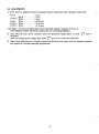
9-3 ADJUSTMENTS
1) Pilot screw is adjusted by'back screwing (counter-clockwise) after closing it fully once.
EY14 . . . . . . . . . . . . . . . . . . . 1 turn
2
BV18 . . . . . . . . . . . turn
EY 18-3 BV21 . . . . . . . . . . . 1 turn
EY23
BV21
. . . . . . . . . . . 1-3/8 turn
EY25-2BV24
. . . . . . . . . . . . 1-5/8 t u r n
EY27-2BV24
. . . . . . . . . . . 1-1/2 turn
CAUTION: DO NOT OVERTIGHTEN PILOT SCREW WHEN CLOSING IT FULLY.
THE NEEDLE POINT MIGHT BE DAMAGED BY OVERTIGHTENING.
2) Turn throttle stopscrewclockwiseuntil
obtained.
When t h e idling speed is higher than 1200
t h e specifiedidlingspeed
of 1200 +loorpm is
+io'rpm turn it counter-clockwise.
3) Make final adjustments to the pilot screw and throttle s t o p screw with air cleaner mounted
and engine at 8 normal operating temperature.
,
-36 -
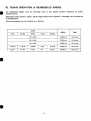
10. RUN-INOPERATION
of REASSEMBLED ENGINE
run-in to get propersurfaceconditiononnewly
An overhauledenginemustbecarefully
installed parts.
Especially when cylinder, piston, piston rings or valves are replaced, a thorough run-in operation
is indispensable.
The recommended run-in schedule is as follows:
r
I
1
I
LOAD
TIME
SPEED
EY14
EY27-2EY18-3
EY25-2
I
EY
23
NO LOAD
2,500 rpm
10 minutes
NO LOAD
3,000 rpm
10 minutes
I
NO LOAD
3,600 rpm
I
10 minutes
1.25 HP
1.75 HP
2.25 PS
2.5 HP
2.75 HP
3,600 rpm
30 minutes
2.5 HP
3.5 HP
4.5 PS
5 HP
5.5 HP
3,600 rpm
60 minutes
- 37 -
I
11. TROUBLE SHOOTING
For a satisfactory starting andrunningconditionsof
a gasoling engine, the following three
requirements must be met:
1. The cylinder filled with a proper fuel-air mixture.
2. An appropriate compression in the cylinder.
3. Good spark at c o r r e c t t i m e to ignite the mixture.
If all three requirements are not met simultaneously, an engine can not be started.
There
are also other factors such as heavy load at starting and too long exhaust pipe causing high
back pressure,whichcontribute
to hardstarting.
The mostcommon causes ofengine
troubles are given below.
c\
11-1 STARTING DIFFICULTIES
11-1-1 FUEL SYSTEM
1) 'Nogasoline in fuel tank, or fuel cock closed.
2) Carburetor insufficiently choked, especially when engine is cold.
3) Water, dirt or gum in gasoline hindering flow of fuel to carburetor.
4) Inferior or poor grade gasoline not vaporizing satisfactorily to produce correct fuel mixture.
5) Needlevalveincarburetorheldopenby
dirt or gum. This condition is ascertained by
continuous fuel drip from the carburetor duringidling.
Sometimes, this trouble is remedied by lightly tapping t h e float chamber with a screw driver
handle or the like.
n
6 ) Due tocarburetorflooding,
too muchfuelintroduced
in the cylinderthroughcranking,
making t h e mixture too rich to be ignited.
When this happens, remove spark plug and turn
t h e engine over several times with starting
pulley to evacuateover-richmixturethroughtheplug
hole. Keep carburetor choke open
during this operation. Dry spark plug thoroughly and reinstall, and try to start again.
11-1-2
COMPRESSION SYSTEM
When the fuel system and the ignition system are eliminatedas t h e cause of starting difficulties
and loss of power, the following are to be checked for possible lack of compression.
1) Cylinder dry after long interruption of operation.
2) Loose or broken spark plug. In this case, a hissing noise is audible, during cranking, made by
escaping mixture gas in compression stroke.
3) Damaged head gasket or slack cylinder head tightening. A similar hissing noise
is produced
during compression stroke.
4) Tappet clearance incorrect. (See "6-3-8, 4) Tappet Adjustment'!)
If t h e compression is not recovered after correcting the above faults, t h e engine must be partly
dismantled and t h e foliowing m u s t be checked.
1) Valve stuck open due to carbon or gum OR valve stem.
2) Piston rings stuck
in piston due to carbon accumulation. Remove pistor! and connecting
from engine and clean, correct or replace parts.
rod
n
-38 -
11-1-3
ELECTRIC SYSTEM
When there is no spark, the following must be checked.
1) Disconnected cable leading to ignition coil, spark plug or contact breaker.
2) Broken ignition coil winding, causing short circuit.
3) Wet or oil soaked spark.plug cable.
4) Dirty or wet spark plug.
5) Incorrect spark plug electrode gap.
6 ) Short connection of spark plug.electrodes.
7) .Pitted or fused breaker points.
8) Sticking breaker arm.
9) Leaking or grounded condenser.
10) Incorrect ignition timing.
11-2 ENGINE MISSES
1) Incorrect spark plug electrode gap.
2) Worn and leaking ignition cable.
3) Weak spark.
4) Loose connections in ignition wire.
5 ) Pitted or worn breaker points.
6) Gasoline containing water.
7 ) Poor compression.
11-3 ENGINE STOPS
1) Fuel tank empty. Gasoline contaminated with water, dirt or gum.
2) Gasoline vaporized in fuel lines due to excessive heating around engine. (Vapor lock)
.3) Vaporlock in fuel lines or carburetor due to the use of too volatile winter
season.
4) Air vent hole in fuel tank cap plugged.
5) Seizure in rotating or sliding pairs in engine due to lack of oil.
6 ) Ignition troubles.
1 1 4 ENGINEOVERHEATS
1) Crankcase oil supply low. Replenish immediately.
2) Incorrect spark timing
3) Low grade gasoline is used.
Engine overloaded.
4) Restricked cooling air circulation.
5) Cooling air partly misdirected causing loss to cooling efficiency.
6) Cylinder head cooling fins blocked with dirt.
-39 -
gas in the hot
7) Engine operated in closed space without fresh supply of cooling air.
8) Restricked exhaust gas outlet.
Carbon deposit in combustion space.
9) Engine detonating due to low octane gasoline with heavy load at low speed.
11-5 ENGINE
KNOCKS
1) Gasoline of poor quality or low octane rating.
2) Engine operating under heavy-load at low speed.
3) Carbon or lead deposits in cylinder head.
4) Incorrect spark timing.
5) Lose or burnt out connecting rod be.aring.
6) Worn or loose piston pin.
7) Engine overheated.
11-6 ENGINEBACKFIRESTHROUGHCARBURETOR
1) Water or dirt in gasoline or poor grade of gasoline.
2) Sticky intake valve.
3) Overheated valves, or hot carbon particles in engine.
4) Engine cold.
- 40
-
12. CHECKS and CORRECTIONS
After'dismantling and cleaning the engine parts,
according to the correction table.
check them, and if necessary, correct them,
The correction table applieswhenever
the engines are repaired.Itscontentsshould
thoroughly understood by those who undertake the repairing. Its specifications must be abided
by t o e f f e c t c o r r e c t m a i n t e n a n c e .
be
Below, terms employed in the correction table are explained.
1) CORRECTION
All operations performed on the engine parts
for the purpose of improving or recovering t h e
engine performance, consisting of repair, readjustment, and replacement.
2) STANDARDSIZE
Design dimension of the part without the tolerance.
3) CORRECTIONTOLERANCE
Tolerance on the re-finished part dimension or on the readjustment dimension.
4) CORRECTION LIMIT
Limit on t h e part and adjustment, beyond which any dimensional and functional change, due to
wear, burn and other causes will adversely affect t h e normal engine performance.
5) USE LIMIT
Limit, beyond which the part is no longer usable, due to defects in function or strength.
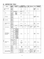
NOTE: All dimensions in t h e "13. CORRECTION TABLE" are given in millimeter, except where
otherwise specified.
-41
-
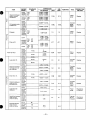
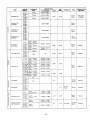
13. CORRECTIONTABLE
t
ITEM
7 ENGINE
Flatness of cylinder
head
CORRECT1 N
STANDARD
SIZE
MODEL
TOLERANCE
LIMIT
USE
"IT
REMARKS
TOOL
surface
,late,
'eeler
0.1 5
EY25-2
EY27-2
CORRECTION
METHOD
Correct
M.018
Bore
Roundness
Cylindricity
Valve seat contact
width
Valve guide I.D.
65 dia.
EY 18-3
EY23
EY25-2
EY27-2
68 dia.
7 2 dia.
7 4 dia.
1.15
0
EY14
EY18-3
EY23
EY25-2
EY27-2
EY14
EY18-3
EY23
EY25-2
EY27-2
Boring
0.01
0.01 5
EY14
EY18-3
EY 23
EY25-2
EY27-2
1.2- 1.5
EY14
6 dia.
EY18-3
EY23
EY25-2
EY27-2
7 dia.
EY14
I
1
O.D.a t skirt, in
N.015
+0.036-+0.016
~~
1
0.1 5
0.15
0.2
0.2
9t middle
>onion
Replace
~~
C
65.480 dia.
I
S.T.D. 67.970 dia.
B
68.220dia.
C
68.470 dia.
EY23
Correct
2.5
S.T.D.61.963 dia.
B
62.213dia.
C
62.463 dia.
I S.T.D. 64.980 dia.
EY18-3 I B
64.230 dia.
thrust direction
(over size)
0.1 5
4.0.01 9
"0.1
-0.02
-0.1
Micrometer
Replace
I S.T.3.71.94
EY25-2
EY27-2
1
EY23
2nd
C
S.T.D. 73.928 dia.
0
74.178dia.
II oil
EY14
EY18-3
Piston pin hole
P
.
,
"
,
1 4 dia.
I"-.--
16dia.
"
EY25-2
EY27-2
1
I
+O .02 5
0
EY18-3 Oil
0.15
Vernier
calipers
Replace
0.035
0.035
Cylinde
gauge
Replace
0.025
Max. cylinder dia. and
piston dia.
0.025 a t skirt in
thrust direction
Cylinde
gauge,
Micrometer
Replace
+0.035
0
+0.002
I
0.15
-0.009
I
I
EY14
EY18-3
EY23
2.8
I Oil
EY25-2
EY27-7
-
Clearance between
piston and cylinde
2.0
2.0
2.0
4.0
Top
EY27-2
2nd
dia.
72.19dia.
72.44
dia.
yp: l:
EY25-2
Width of ring
groove
B
I
I
0.037L-0.075L
0.030L-0.069L
0 0 6 L- 0.099 L
0.072L-0.111
-42
-
L
USE
L,MIT
Clearance between
piston
ring groove
I
EY18-3
EY23
0.01OL-0.055L
TOP
Oil
2nd
EY18-3
0.15L
'
2:
Fl
Ring gap
REMARKS
TOOL
CORRECTION
METHOD
0.050L-0.095L
0.040 L- 0.085 L
EY25-2
2nd
EY27-2 Top
EY14
Oil
Feeler
0.15
w w
0.050L-0.095L
0.04OL-0.085L
0.01OL-0.065L
EY 14
0.009T-0.010L 18-3
EY
F i t betweenpistonEY23
& piston pin
EY25-2
EY27-2
r
l
Replace
0.06L
0.06L
Cylinder
gauge
Micrometer
Replace
1.5
1.5
Feeler
gauge
Replace
Micrometer
Replace
Micrometer
Replace
Cylinder
gauge
Replace
Cylinder
gauge
Micrometer
Replace
0.08
Cylinder
gauge
Replace
0.1 2
Cylinder
wage
Micrometer
Replace
Feeler
gauge
Remachine
or Replace
0.004T- 0.01 5 L
0.20-0.40
EY25-2
EY2722
0.05-0.25
-0.05h -0.07
-0.04Top
2.5
-0.060
4.01--0.03
Ring width
-0.1
-0.1
-0.07
-0.04- -0.06
-0.05-
-0.01-4.03
2 .a
14 dia.
Piston pin O.D.
1
I
EY25-2
EY27-2
EY14
Large
end
I.D.
I
I
I
16 dia
I
I
,
dia.
24
0
4.008
-0.04
-0.005
-0.01 3
~~
1
EY 18-3
+0.01326 dia.
EY23
EY25-2
EY27-2
0.076L
29L
I
I
0
I
1
0.1
28 dia.
EY14
Clearance between
r o d lameend 1.D.
and cr& kpin
I E??!-3 I
-~
EY25-2
EY27-2
0.04L-0.066L
14 dia.
Small end
o*2
i-o.021-+0.01
I.D.
EY25-2
EY27-2
0.01 Clearance between
small end 1.0.
and piston pin
16
M.027-+0.016
dia.
0.12
EY25-2
EY27-2
1
0.021 L-0.WOL
L- 0.7 L
clearance
EY 18-3
EY14
I
Parallelism between
'
EYf8-3
large end and
E Y23
small end bores
EY25-2
EY27-2
Distance between
large end and
small end bores
EY25-2
EY27-2
0.1
Test bar
& Dial
indicatol
0.1
0.05
-0.1
-43 -
0.15
1
Remachine
or Replace
1
CORRECTION
STANDARD
ENGINE
ITEM
MODEL
z
1
SIZE
EY -14
EY 18-3
Crankpin O.D.
EY25-2
EY27-2
I
EY14
EY18-3
EY 23
EY25-2
EY27-2
Crankpin O.D.
roundness
EY14
EY18-3
EY23
EY25-2
EY*7-2
I
I
1
Crankpin O.D.
cylindricity
I
Crankpin O.D.
parallelism
EY14
EY 18-3
EY25-2
EY23
EY27-2
I
1
TOLERANCE
2 4 dia.
-0.050-0.063
2 6 dia.
-0.037-0.050
28 dia.
-0.040.-
0.053
USE
LIMIT
LIMIT
I
I
I
1
Micrometer
I
I
I
I
Micrometer
below 0.008
Dial
indicato
I
I
Cam lobe height
1
EY 18-3
EY25-2
EY23
I
4.01 2
I
1
I
1-
{:;e:'
EY 18-38
Drive s. 25 dia.
EY23B Mag.s. 17dia.
EY18-3D Drive s.
EY23D
!Mag.
s. l7
dia.
EY25-2B j Drive s. 30 dia.
iMaq.
EY27-28
s. 2 0 dia.
-0.016~-0.027
I
EY25-20 Drive s. 15 dia.
EY27-2D Mag. s. 15 dia.
-0.25
EY14
EY18-3
EY14
I
EY18-3 I
EY23
EY25-2 I
EY27-2
I
Squareness
Clearance between
stem and guide
I
I
I
'
0.05
~ o ~ 0 3 2 ~ ~ o ~ 0 4 3
I
1
I
I
'
Ij
I
-1-5
I
I
0.05
-
ilntake
EY18-3
/Exhaus7
Intake
EY23
EY25-2 Exhaust
EY27-2
dia.
I
j
20.025,b -0.040
0.075~-0.095
,
I
0.025L-O.C)55L
j
0.075L-0.110L
.
1
~~~
I1
iI
l.o
:or total
ength
0.3
4t middle
1
0.056L-0.098L
-44
-
Micrometer
Replace
i
0.3
,
calipers
I
I
!Intake
1 Exhaust
I
I
I
32
Replace
0.05
0.05
~
I
1
Micrometer
'
I
-0.003--0.012
I
-0.25
]
"0.003~-0.012
"0.016--0.027
1
I
I
fl.1
"0.003-"0.012
Drive s. 22 dia.
Mag. s. 15dia.
4.016-"0.027
dia.
--0.016~--0.027
15
EY14D
-0.05
-0.009-0
24.95
30.8
4
-0.003--0.012
Drive s. 3o dia
Mag. s.
1
Remachine
or Replace
Micrometer
-0.05
EY14
CORRECTION
METHOO
0.15 0.15
below 0.005
-0.003EY25-2
EY27-2
I
? EMAR KS
below 0.005
Crankshaft
journal O.D.
Journal O.D.
i
I
Replace
Square
~
Cylinder
Replace
ITEM
STANDARD
SIZE
ENGINE
MODEL
EY14
Tappet clearance
Clearance between
groove and retainer
I
CORRECTION
TOLERANCE
LIMIT
USE
LIMIT
REMARKS
TOOL
CORRECTION
METHOD
0.10L-0.14L
below
EY 18-3
EY 23
E Y 25-2
EY27-2
0.0:
0.16L-0.2OL
EY14
EY18-3
FY23
2.5
0.04L-0.12L
EY25-2
EY27-2
2.5
0.04L-0.15L
Correct
above
0.25
0.5
0.5
Correct
EY14
Stem end length
4.0
-2
.o
-2
.o
Venier
calipers
Replace
Venier
calipers
Replace
Cylinder
gauge &
Micrometer
Replace
EY27-2
Total length
EY 14
38.12
EY18-3
EY 23
46
E 25-2
Y
EY27-2
50.9
EY14
Clearance between
stem and guide
Metering needle
unscrew
Pilot screw
unscrew
Fixed
EY 14
1
Spark plug
-0.5
-0.5
0.2
0.2
20.05
f1f4
BV18 2
BV21 1
B V 2 11 - 3 B
E Y 25-2
EY27-2
EY14
EY18-3
+Q.06
0.025L-0.062L
EY 14
EY 18-3
EY 23
EY25-2
EY27-2
EY 23
-
0.013L-0.037L
EY18-3
EY23
EY 25-2
EY27-2
EY18-3
0
1-518
1-1/2
NGK 3 4 H S
NGK BP4HS
Spark gap
EY14
EY 18-3
EY23 EY25-2
EY27-2
Spark timing
EY 14
EY 183
EY23
23' before T.D.C.
EY25-2
EY27-2
Point opening
0.6- 0.7
EY14
EY 18-3
0.4
EY25-2
EY27-2
0.35
25 O
Timing
tester
Adjust
50.1
Contact
breaker
spanner
Adjust
kO.1
20.05
- 45 -
Adjust or
Replace
1
ITEM
MODEL
Max. Output
Continuous Rated
output
ITEM
Fuel Consumption
ITEM
CORRECTION LIMIT
HPIrpm
EY14D
3.5l4.000
EY183D
5.0/4,000
EY23D
6.014,OOO
EY25-2D
7.014,000
EY27-2D
7.514.000
EY14D
2.513.600
EY18-3D
3.513.600
EY23D
4.513.600
EY25-2D
5.013.600
EY27-2D
5.513.600
MODEL
literlhr
EY14
1.o
EY 18-3
1.5
EY23
1.9
EY25-2
2.2
EY27-2
2.3
MODEL
EY14
REMARKS
,”.
Below 110%of rated output
REMARKS
a h r
USE LIMIT cc/hr
15
50
EY 18-3
50
REMARKS
15
Lubricant
EY23
50
15
Consumption
EY25-2
28
”
-
EY27-2
ITEM
’
Special Lubricant
Quality
60
liter
MODEL
EY14
-
30
,
REMARKS
0.50
EYl8-3
0.70
E Y23
0.65
Use the class SC or nigher grade Engine Oil
Below -1OOC (14’F)
SAE 1OW-30
-1OOC (14OF) -2OoC I68OF)
SAE #20
2OoC /6S0F) -4OOC (104OF)
S A € #30
EY25-2
0.85
EY27-2
ITEM
Oil Change
I
I
MODEL
EY14
1
FREQUENCY OF OIL CHANGING
First Time: Change
operation.
hours
oil
20after
Second Time and Thereafter: Change oil every 50 hours operation.
-46 -
I
I
ITEM
14
MODEL
I
kg/ud/rpm
EY
4.61420
18-3EY
5.91360
Cylinder Pressure
EY23
6.7 1380
EY25-2
5.51420
EY27-2
5.51420
ITEM
Min. accelerating
revolution
I
MODEL
EY23
EY18-3
EY14
2
Connecting r o d
bolts
EY 18-3
EY23
:LzP
I-
EY27-2
EY14
F
nuts
1
kg-crn
I
1
330-360
340-370
I
90-115
170- 200
1
I
I
I
1
I
23.8-25.9
24.6-26.7
6.5-8.3
12.3-14.4
I
I
200-250
450-500
1
I
1
I
I
I
I
14.4- 18.0
I
I
I
1
I
32.6-36.1
Torquewrench
Torquewrench
1
I
I
Torque wrench
I
1
EY14
I
Spark plug
80-100
I
5.8-7.2
I
Torque wrench
170190
250-290
12.3- 13.7
I
I
230-270
I
EY25-2
EY27-2
TOOL
43.5-47.0
600- 650
EY25-2
EYl8-3
ft-ib
16.6
13.7-
EY18-3
EY23
EY25-2
EY 27-2
EY14
Main bearing cover
bolts
REMARKS
600- 650
EY25-2
EY27-2
I
TOOL
Tachometer
230
190EY14
I
Pressure gauge
1,200- 1,300
EY14B
EY 18-38
EY23B
EY25-2B
EY27-2B
ITEM
Cylinder head
clamp nuts
TOOL
70% of normal value
MODEL
EY 14D
EY183D
EY23D
EY25-2D
EY27-2D
I
CORRECTION
LIMIT
260- 18.8-21.7
300
-47 -
I
REMARKS
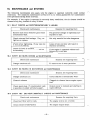
14. MAINTENANCE and STORING
n
Thefollowingmaintenancejobsapplywhentheengineisoperatedcorrectlyundernormal
conditions. The indicated maintenance intervals are by no means guarantees
free operations during these intervals.
For example, if t h e engine is operated in extremely dusty conditions, the
cleaned every day, instead of every 5 0 hours.
14-1 DAILY CHECKS and MAINTENANCE(EVERY
for maintenance
air cleaner should be
8 HOURS)
Checks and maintenance
Reasons for requiring them
Remove dust from whatever parts which
accumulated dust.
The governor linkage is especially susceptible to dust.
Check external fuel leakage. If any, retighten or replace.
Not only wasteful but also dangerous
Check screw tightening. If any loose one
is found, re-tighten.
Loose screws and nuts will result in
vibration accidents.
Check oil level in crankcase and add up
as necessary.
it
I
If t h e engine is operated without sufoil,
ficient
will fail.
14-2 EVERY 20 HOURS CHECKS and MAINTENANCE
Checks and maintenance
Reasons for requiring them
Change crankcase oil.
-\
To remove run-in wear particles.
14-3 EVERY 50 HOURS (10 DAY) CHECKS and MAINTENANCE
maintenance
Checks
and
I
Change crankcase oil.
Contaminated oil a c c e l e r a t e s wear.
Clean air cleaner
Clogged air cleaner harms engine operation.
,
Reasons for requiring them
!
-
Output power is reduced and starting is
made difficult.
Check spark plug. If contaminated, wash
in gasoline or polish with emery paper.
14-4 EVERY 100 - 200 HOURS (MONTHLY) CHECKS and MAINTENANCE
I
i
Checks and maintenance
Reasons
requiring
for them
I
”
”
Clean f u e l filter and fuel tank.
_
”
=engine will
be out of w d e r .
”
The engine output drops.
Clean contact breaker points.
- 48 -
”
14-5 EVERY 500 -600 HOURS(SEMIANUAL)
CHECKS and MAINTENANCE
Reasons for requiring them
Checks and maintenance
Remove cylinder head and remove carbon
deposit.
The engine will be o u t of order.
Disassemble and clean carburetor.
~
14-6 EVERY 1000 HOURS (YEARLY) CHECKS and MAINTENANCE
>
Reasons for requiring them
Checks and maintenance
Perform overhauls, clean correct or
replace parts.
The engine output drops and become out
of order.
Change piston rings
To prevent-from danger caused by t h e
f u e l leakage.
Replace fuel pipe once a year.
14-7 PREPARATION for LONG-TERM STORAGE
1) Perform the above 13-1 and 13-2 maintenance jobs.
2) Drain fuel from t h e fuel tank and carburetor float chamber.
3) To preventrustin
t h e cylinderbore,applyoilthrough
crankshaft several turns by hand. Re-install t h e plug.
t h e sparkplug
hole andturn
4) Turn t h e starting pulley by hand and leave it where the resistance is t h e heaviest.
5) Clean t h e engine outside with oiled cloth.
6) Put a vinyl or other cover over t h e engine and store t h e engine in dry place.
-49
-
the
Industrial
Engines