1
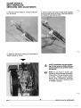
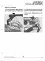
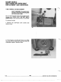
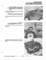
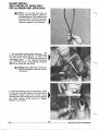
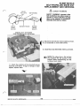
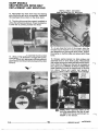
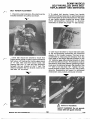
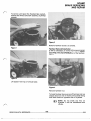
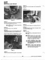
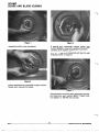
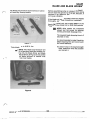
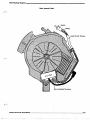
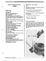
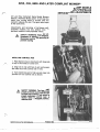
4250, 4505, 8605 AND LATER COMPLIANT MOWERS
SCAMP MODELS
SELF-PROPELLED
SERVICING AND ADJUSTMENTS
All LawnBoy Compliant Scamp ModelMowers
feature a Flywheel Brake system. It will stop the
bladefromturningwithin
3 secondsafterthe
operator releases the bail. The engine also stops
at the same time.
Adjustmentsand servicing of the Scamp selfpropelledmowers
are
very
differentfromall
previous models of self-propelled mowers.
SAFETYWARNING: Before anyadjustmentsor repairs are attempted,
disconnect and remove spark plug to
prevent starting.
INSTALLING CONTROL ROD
1. Place retainer clip on clutch arm with long side
of clip on the inside of clutch arm.
2. Align hole in clip with hole in arm and assemble lower end of the control rod in hole.
3. Turn (swivel) long end of clip up and snap into
position on lower control rod as shown.
SAFETYWARNING:The
lower selfpropel control rodmust be assembled
to clutcharm as shown.If not theselfpropel mechanism will not return to
neutral when thecontrol
lever is
released from the engaged position.
SCAMP MODELS
SELF PROPELLED
SERVICING AND ADJUSTMENTS
4. With the control handle in “neutral”
(free) posi-
tion as shown.
6. Secure upper and lower control rods together
with the clampscrew as shown.This screw should
be tightened securely by hand.
5. With the clutch arm resting on the handle and
wheel bracket as shown.
SAFETY WARNING: Improper tightening of clamp screwon control rod may
result in operator loss of drive control
mechanism.
NOTE: To put mower in motion, pull
upward oncontrol handle andhold in
drive position. To stop forward motion
of mower, release control handle.
Mower drive mechanism functions
only when the control handle is held
in “DRIVE” position.
19.42
1983
SERVICE BULLETIN REFERENCES
SCAMP MODELS
SELF PROPELLED
SERVICING AND ADJUSTMENTS
DRIVE ROLLER ADJUSTMENT
1. With the control handle in “Neutral”, place both
2. Loosen bolt and nut located in drive roller gap
rear wheel height adjusters in #1 (lowest) cutting adjusting slot on each side
of drive roller bracket.
position as shown. A gap of 3/16” should appear
between
the drive rollers
and tires.
3. Move the drive roller
bracket up
or down to obtain thenecessary 3/16’’ drive roller gap. Hold
bracket in position and tighten both bolts and nuts
securely.
SCAMP MODELS
SELF-PROPELLED DRIVE BELT
REPLACEMENT AND SERVICING
V BELT REMOVAL OR REPLACEMENT
SAFETY WARNING: To prevent starting engine, disconnect spark plug lead
and remove spark plug.
The “V” belt used onthe utilityself-propelled model
mowers is a SPECIALBELT. DO NOTUSE A
SUBSTITUTE. It won’t work as WELL or as LONG.
To remove the belt:
1. Remove four belt guard cover screws and
remove cover.
2. Turn mower up on side and remove nut, blade
and collar. Remove three bolts securing muffler and
crankshaft support. Remove muffler.
19-44
1983
SERVICE BULLETIN REFERENCES
SCAMP MODELS
SELF-PROPELLED DRIVE BELT
REPLACEMENT AND SERVICING
SAFETY WARNING: To prevent starting of engine, disconnectand remove
spark
plug
prior
to removing
the
engine.
3. Remove three bolts securing engine to muffler
plate and remove engine.
NOTE: Do not remove muffler plate
from housing when removing engine.
4. Remove engine and remove drivebelt from drive
pulley.
SAFETYWARNING: Do notoperate
mower with belt guard removed.
5. Remove roll pin from left hand drive roller and
remove roller.
6. Remove belt from driven pulley and slide shaft
assembly to the right.Remove belt frommower as
shown.
SCAMP MODELS
SELF-PROPELLED DRIVE BELT
REPLACEMENT AND SERVICING
NOTE: After thebelthas
been removed, examine for broken, cracked or
misaligned pulleys. The condition and
the wear pattern of the belt will provide cluesfor the above possibilities.
Replace damaged or worn pulleys.
7. The crankshaft pulley (drive pulley) is secured
to the crankshaftwith a SPECIAL slotted set screw.
Theend of this screw locates in ahole in the
crankshaft. The correct position and tightness is
very
IMPORTANT.
If nottightened
securely,
damage to the pulley, crankshaft and premature
wear of the drive belt will result.
NOTE: Apply OMC Ultra-Lock Part No.
388517 to threads of set screwprior to
installation.
8. When reinstalling pulley to crankshaft, the side
of the pulley with set screw is the lower side. If
assembled
upside
down
(set screw
on
top)
misalignment and interference of pulley operation
will result. Alwayscheck
pulley for damage.
Replace if necessary.
19-46
1983
SERVICE BULLETIN REFERENCES
SCAMP MODELS
SELF-PROPELLED DRIVE BELT
REPLACEMENT AND SERVICING
IDLER
PULLEYS
SAFETY WARNING
TOP STRAND
1
DRIVEBOTTOM
STRAND
ENGINE
SHAFT
PULLEY
SAFETY WARNING: Incorrectdrive
belt installation may allow mower to
operate in reverse direction causing
injury to the operator or bystanders.
Assemble drive belt as shown.
DRIVE
PULLEY
INSTALL BELT AS SHOWN
FOR PROPER PULLEY ROTATION
11. Check the condition of the drive shaft, bronze
bearings, and sleeve. If signs of damage or wear
appear, replace them.
1983
SERVICE BULLETIN REFERENCES ...................................................................................................................................................................
19.47
SCAMP MODELS
SELF-PROPELLED DRIVE BELT
REPLACEMENT AND SERVICING
INSTALL BELT AS SHOWN
FOR PROPER PULLEY ROTATION
12. Reassemble the drive shaft into the bearing
and slide it to the left
as far as possible. Assemble
the washer and drive roller on the drive shaft.
13. The drive rollers must be properly installed to
utilize the self-cleaning
feature. Properinstallation
is with the vee pointing toward the wheel.
15. As you face the front of the mower, twist the
forward end of the belt 1/4 turn counter clockwise
and assemble on the enginedrive pulley. Assemble engine on muffler plate andsecure with three
bolts.
14. Using a new roll pin, assemble the drive roller
to the drive shaft. Use a 5/32” or larger drift punch,
drive the rollpin into place, flush with the outer
surface. Neither end should protrudebeyond the roller
surface.
16. Release spring tension on idler pulleys and
assemble belt on drive shaft pulley. Reassemble
idler pulley spring and rotate the belt several revolutions. Check to make sure the belt is centeredon
the’ pulleysand TURNING IN RIGHT DIRECTION.
Note direction of arrow on large pulley in illustration above.Check
andadjust
belt tension if
necessary. Referto BELT TENSION ADJUSTMENT.
NOTE When replacing either of the.
belt idler assemblies, use idler kit part
no. 682374for the top and kitpart no.
bottom.
682564
the on
19-48....
1983
SERVICE BULLETIN REFERENCES
2. Drive beltshould be checked to insure that
proper tension exists in order to prevent premature
belt failure. Lift floatingidler from theupper strand
of “V” belt. Belt will then become loose.Set
floating idler onto “V” belt and check clearance
between thetwostrands
of the “V” belt. The
distance between the two strands should not be
less than 112” as shown.
complished by measuring the distance from the
front edge on the height adjuster brackets to the
1/4” diameter gage holes located directlyin front
of these brackets as shown.This distance mustbe
the same for bothsides. Before tightening screws
make sure the distancebetween the strandsof the
“V” belt is not less than 112”. Tighten the four
handle bracket screws and the two side screws
securely.Reassemble beltguardto
self-propel
previously
screws
mechanism
using
removed.’
SAFETY WARNING
SAFETYWARNING: Do notoperate
mower with belt guard removed.
SERVICE BULLETIN REFERENCES
1983
19-49
SCAMP MODELS
SELF-PROPELLED DRIVE BELT
REPLACEMENT AND SERVICING
LUBRICATION
50 HOURS
FOUR PLACES
1. DRIVE
ROLLER
BEARINGS-Disassemble
rotating shaftcover from self-propel mechanism by
removing four screws. Unscrew plug from end of
each drive roller (Point
“A”). Fill exposed cavity with
LAWN-BOY “A” GREASE,PART NO. 610726 OR
EQUIVALENT. Replace plug and tighten until snug.
Repeat procedureuntil lubricant appears oncrossshaft at Point “B”. Reassemble rotating shaftcover
to self-propel assembly.
LOWER IDLER ASSEMBLY
BOLT-PULLEY-ARM-NUT
PART #682564
LOWER IDLER PULLEY-Permanently lubricated.
No lubrication required.
FLOATING IDLER PULLEY-Do not immerse the
idler pulley in solvent. Use a rag containing solvent,
clean the holein the idler pulleyand the shoulder
bolt thoroughly. Using a small amount of LAWNBOY “A” GREASE or EQUIVALENT, relubricate the
shoulder bolt and remount idler pulley assembly in
the same order it was originally.
AS REQUIRED
1. CLUTCH LINKAGE-Apply several drops of light
machine oil on clutch mechanism at all pivoting
points.
19.50
1983
...........................SERVICE
BULLETIN REFERENCES
SCAMP
BRAKE SERVICING
AND REPAIR
To service and repair
system,
flywheel
brake
the
remove the shroud and tank assembly.(5 Phillips
screws).
Figure,3
Remove flywheel screen. (3 screws).
Figure 1
Flywheel Removal/Installation
It will be necessary to move the Flywheel Brake
Arm away from the flywheel (pull back oncontrol
bail) to allow removal orinstallation of the flywheel.
Figure 2
Lift spacer from top of shroud base.
Figure 4
Remove flywheel nut.
To break flywheel looseuse a softhammer and rap
sharply down onone of the thick fins while lifting
with other hand on opposite side of flywheel.
NOTE: Do not breakany
fins on
flywheel. It will be unbalanced and
vibrate.
SERVICE BULLETIN REFERENCES
1983
19-51
SCAMP
BRAKE
SERVICING AND REPAIR
Pull bail back against the handle
brake.
to release the
Lift flywheel off.
Flywheel Configurations
1983 Flywheels are muchtallerthanprevious
models. As Fig. 5 shows, the visual difference is
quite apparent.
NOTE These newflywheels are not interchangeable with those ofprevious
Lawn-Boy models.
Figure 6 .FlywheelBrakeSystemComponents
1983
Years
Previous
1. Retainer Clip
2. cup
Figure 5
3.
4.
5.
6.
7.
8.
9.
10.
FlywheelHeightComparison
“Pigtail” Spring
Circuit Switch
Switch Retaining Screw
Adjusting Bolt
Locknut
Brake Arm
Brake Arm Bolt
Cable Retainer Spring
It is important to note that two different materials
are used on compliancemowerflywheels.
Flywheels for all Flywheel Brake models are made
of aluminum, but due to the need for additional
rotating weight (inertia), the Blade Brake Clutch
(BBC) flywheels are made of zinc. The zinc
flywheels are plainly marked as such to prevent
Pad
Brake
Wearconfusion. Be certain you install only thecorrect
Flywheel Brake Arm (with bonded brakepad) must
type flywheel for the specific mower.
be replaced if pad wears below .030” at any spot.
SAFETYWARNING:FlywheelBrake
(Zone
and
PRS)
and
Blade
Brake
Clutch (BBC) flywheels are not interchangeable. The correct type flywheel
(aluminum or zinc) is
critical to proper
CPSC compliance.
.030”Minimum
Figure 7
19-52
FlywheelBrakePadWear
SERVICE BULLETIN REFERENCES
SCAMP
BRAKE
SERVICING AND REPAIR
To replacethebrake arm, itwill be necessary to
disconnectthebrakecablefromthe
engine.
Setflywheel
the back
STEP #6
Thoroughlycleanthethreads of thebolt and apply
Lawn-Boy Screw Lock, part number 384848 to the
threads.
on the engine.
STEP #7
Assemble the brake arm and bolt onto bracket.
Tighten to 5-7 ft. Ibs. (63-75 in. Ibs.)
STEP #8
Reassemble thecable
bracket assembly.
retainer spring intothe
STEP #9
It isnecessary to check thebrake cable adjustment
before reinstalling it in the bracket.
Figure 8
STEP #1
With flywheel in placeand the bail controlreleased
(out of operating position), compress the “Pigtail”
Spring by hand,then remove the Retainer Clip, Cup
and Spring.
STEP #2
Remove the cable from the housing.
Remove the flywheel.
Figure 9
STEP #3
Remove circuit switch adjusting bolt
and lock nut.
(See Fig. 6).
STEP #10
To adjust the brakecable, loosen the jam nutand
back it off.Place the brake cable adjusting
gauge,
part number 611703over the end of the cable.
Assemble theretainer clip (see Fig. 9) on the cable
against the gauge.
STEP #4
Remove brake armbolt and brake arm.(See Fig. 6).
STEP #5
Re-assemblecircuit switch adjusting bolt
and lock
nut into thenew brake arm. Turnit into bracket until
head is against the bracket. (See Fig. 6).
SERVICE BULLETIN REFERENCES
Turn adjusting nut up against thegauge to apply
approximately 5 Ibs. tension.
1983
19-53
SCAMP
BRAKE
SERVICING AND REPAIR
STEP #2
Place a mark on the plunger end
at of gauge. (See
Fig. 11).
STEP #3
Remove the gauge.
Figure 10
STEP #11
Turn jam nut against the adjusting nut
and tighten.
Do not permit adjusting nut to turn.
Figure 12
STEP #4
Pull the bail backagainstthehandleandhold
Use 1/2”Open end wrenches.
(See Fig. 10).
it.
STEP #12
Set flywheel back on the crankshaft.
STEP #5
Turn adjusting boltin untilmark on plunger is flush
with face of switch body.
STEP #13
Reassemble the Cable into the BrakeBracket, then
reassemble the Spring, Cup and Retainer Clip.
STEP #6
Tighten
nut.
NOTE Be sure adjusting boltdoes not
turn.
After the brake cable is reassembled, it is necessary to check the circuit switch adjustment.
NOTE Recheck thisswitchadjustment to prevent the plunger from going in toofar anddamaging the switch
internally. If it does not move in far
enough, the engine will not start.
SAFETYWARNING:Properadjustment of this switchis necessary to insure that blade motion stops within
the required time.
NOTE If proper switch adjustment
cannot be made, check brake cable
adjustment (See Fig. 9) as this will affect correct switch operation.
Figure 11
STEP #1
Place the switch adjusting gauge on the plunger.
19.54
1983
SERVICE BULLETIN REFERENCES
I
SCAMP
IGNITION CIRCUIT SWITCH
TESTING AND REPLACEMENT
Trouble
shooting
circuit
the
switch.
STEP #1
Disconnect both leads
from
the
STEP #7
‘-Using a driftpunch and hammer, drive the switch
body out of the bracket.
Fig.(See
13).This will break
C.D. pack.
the
flange
on
the
switch.
STEP #8
Assemble the new switch and lead assembly into
the bracket.
STEP #2
Connect a continuity meter
or light tothese leads.
STEP #3
Push the plunger in. The meter shouldread “0”or
the light should go out.
STEP #9
Install the switch retainer screw. Reconnect the
two leads onto the C.D. pack.
STEP #4
Release the plunger. The meter should indicate a
completed circuit or the light will go on.
STEP #10
Adjust the switch plunger travel with the gauge,
part number 61 1702.Follow steps1 thru 6 on page
14.
If the switch isdefective, it requires replacement.
SAFETYWARNING:Properadjustment of this switchis necessary to insure that blade motion stops within
the required time.
Figure 13
STEP #5
To replacethe switch, itwill be necessary to
remove the flywheelfor access to theswitch. This
permits the brake arm to swing out of the way.
STEP #6
Remove the switch retainer screw. (See Fig. 6).
SERVICE BULLETIN REFERENCES
1983
19-55
SCAMP
BLADE AND BLADE HOUSING
Figure 1
Figure 3
Assemble muffler onto crankshaft.
A specialtool.crankshaftsupport
gauge, part
support
number 609968 is required to position the
correctly do it doesn’t contact the crankshaft.
Slide the gauge onto crankshaft with the thin wall
of gauge inside of support.
Figure 2
Always assemble the crankshaft support
with the
flange down towards the blade.
Figure 4
Clean threads on muffler
bolts thoroughly andapply Ultra-Lbck, part number 388517. Install bolts
and tighten to 150-190 inch pounds.
19-56..
1983
SERVICE BULLETIN REFERENCES
SCAMP
BLADE AND BLADE HOUSING
The Blade and Hardwareshown beloware usedon
all Lawn-Boy Scamp models.
Before assembling collar on crankshaft, checkto
be sure it did not get bent or distorted
when being
removed. If so, replace it. Do not use, because, it
will cause vibration.
If the blade nut is to re-used,
be
clean the threads
thoroughly. Also clean threads on crankshaft.
Apply OMC Ultra-Lock, part number 388517 on the
threads. Torque blade nut to 45-50 foot pounds.
NOTE After repairs are completed
always test the mower for starting,
running and blade stoppage time.
The required blade stopping timeis 3
seconds or less.
It isrecommendedto make 3 tests for
blade stopping time and record each
for future reference.
Figure 5
Torque blade nut to 45-50 ft. Ibs.
NOTE: This Blade and Hardware will
fit all previous Lawn-Boy mowers, using only the Blade Driver and Blade
Nut (as shownin Fig. 5). Do not use the
old bladestiffener orwasher with
these new blades.
Figure 6
SERVICE BULLETIN
REFERENCES
1983
If itdoesn't stopin the required length
of time, determine what the problem
is and correct it.
Zone Start Models
Brake Cable Routing (console)
Tie Wrap Locations
1. Single Tie
2. Double Tie
Retainer Cup Removal
Hose and Cable Routing
Primer Assembly
19-60
I.Primer Hose
Brake Cable
3. Brake Cable Retainer Clamp
4. Switch Cable Clamp
SERVICE BULLETIN REFERENCES
Wire Routing Diagram
Zone (manual) Start
Tubing
SERVICE BULLETIN REFERENCES
19-61
19-62
SERVICE BULLETIN REFERENCES
TROUBLE SHOOTING
Engine Won’t Startor Hard Starting
SCAMP
Ignition Circuit (“Kill”) Switch
(Zone)
The following conditions are indications of Switch
misadjustment or failure.
Possible Cause
No fuel in tank.
Fuel valve off.
Insufficient or excessive priming.
Spark plug lead disconnected.
Spark plug fouled.
Low compression in cylinder (80 PSI min.)
Incorrect air gap between C.D. pack and flywheel.
C.D. pack defective. (Refer to “CD Pack Testing,”
Pg. 15)
Primer hose disconnected from carburetor or connector.
Primer hose restricted. (Refer to “Primer System
Draining,” Pg. 63)
Air filter restricted.
Carburetor needle valveincorrectly adjusted.
Throttle valve stuck closed.
Carburetor-to crankcasescrews not tight.
Carburetor-to crankcasegasket leaking air.
Float chamber screws loose.
Float chamber gasket leaking air.
Restriction in high speed nozzle.
High speed nozzle loose.
Float valve stuck closed.
Restriction in fuel passages (tank, valve, hose,
float valve seat).
Float level set too low.
Reed Valves stuck closed or bent open more than
.015”.
Air leak between crankcase halves.
Intake plug leaking or missing.
Main bearing seals leaking.
Exhaust system restricted.
Zone Start Models
Bail not pulled backagainst handle.
Incorrect kill switch adjustment
(See Pg. 54 Fig. 12)
Kill switchinoperative. (See “Ignition Circuit Switch
Troubleshooting,” Pg.19-17).
Brake dragging on flywheel.
SERVICE BULLETIN REFERENCES
Engine misfireswhen in self-propelling mode
Adjust Switch (See Pg. 54 Fig. 17).
Engine stops if bailis not heldextremely tight
against handle
Adjust Switch (See Pg. 54 Fig. 17).
Engine won’tstart (no spark)
Adjust or replace switch
Primer System Draining
If a mower is tipped back on its handle (as shown
below), fuel may runfromthe
carburetor and
settle in the lowest point of the primer line when
the machine is set upright. If this occurs, remove
the primer hose from the carburetor and drain the
fuel. Symptoms includerichrunning
and hot
starting problems.
19-63