1
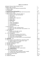
TABLE OF CONTENTS
INTRODUCTION OF THE OWNERS MANUAL
GENERAL PRECAUTIONS
1. PRECAUTIONS TO BE HEEDED FOR OPERATION
2. NAME OF PARTS
3. ACCESSORIES
4. ASSEMBLY AND INSTALLATION
5. PRECAUTIONS TO BE HEEDED WHEN MOVING MACHINE
6. CONTENTS OF GAME
7. EXPLANATION OF TEST AND DATA DISPLAY
7-1 SWITCH UNIT AND COIN METER
7-2 TEST MODE
7-3 MEMORY TEST
7-4 STEERING REACTION TEST
7-5 INPUT TEST
7-6 OUTPUT TEST
7-7 SOUND TEST
7-8 C.R.T. TEST
7-9 GAME ASSIGNMENTS
7-10 COIN ASSIGNMENTS
7-11 BOOKKEEPING
7-12 BACKUP DATA CLEAR
8. HANDLE MECHA
8-1 REMOVING THE CONTROL PANEL
8-2 REPLACING AND ADJUSTING THE HANDLE’S VR
8-3 GREASING
9. SHIFT LEVER
9-1 REMOVING THE SHIFT LEVER
9-2 SWITCH REPLACEMENT
10. ACCEL & BRAKE(S)
10-1 ADJUSTING AND REPLACING THE VR
10-2 GREASING TO FOOT BRAKE AND ACCEL
10-3 GREASING TO HAND BRAKE
10-4 REPLACING THE MICROSWITCH ON HAND BRAKE
11. COIN SELECTOR
12. MONITOR
13. REPLACEMENT OF FLUORESCENT LAMP AND LAMPS
13-1 REPLACEMENT OF FLUORESCENT LAMP
13-2 REPLACEMENT OF LAMPS
14. PERIODIC INSPECTION TABLE
15. TROUBLESHOOTING
16. GAME BOARD
16-1 REMOVING THE GAME BOARD
16-2 REPLACMENT OF FUSE
16-3 COMPOSITION OF THE GAME BOARD
16-4 ERROR DISPLAY
17. COMMUNICATION PLAY
17-1 INSTALLATION PRECAUTIONS
17-2 CONNECTING THE COMMUNICATION CABLES
17-3 SETTING FOR COMMUNICATION PLAY
18. DESIGN RELATED PARTS
19. PARTS LIST
20. WIRING DIAGRAMS
1
2~3
4~5
6
7~8
9~15
16
17~21
22~32
23
24
24
25
26
26
27
27
28
29~31
32
32
33
33
34
35
36~37
36
37
38~40
38
39
40
40
41~43
44~46
47~48
47
48
49
50
51~55
51
52
53
54~55
56~59
56
56~58
59
60~61
62~103
XXX
1st PRINTING MAR 98
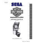
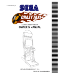
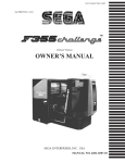
TWIN TYPE
OWNER’S MANUAL
SEGA ENTERPRISES, USA
MANUAL NO. 4200-6374-03
Warranty
Your new Sega Product is covered for a period of 90 days from the date of shipment. This certifies
that the Printed Circuit Boards, Power Supplies and Monitor are to be free of defects in workmanship or materials under normal operating conditions. This also certifies that all Interactive Control
Assemblies are to be free from defects in workmanship and materials under normal operating conditions. No other product in this machine is hereby covered.
Sellers sole liability in the event a warranted part described above fails shall be, at its option, to
replace or repair the defective part during the warranty period. For Warranty claims, contact your
Sega Distributor.
Should the Seller determine, by inspection that the product was caused by Accident, Misuse, Neglect, Alteration, Improper Repair, Installation or Testing, the warranty offered will be null and void.
Under no circumstances is the Seller responsible for any loss of profits, loss of use, or other damages.
This shall be the exclusive written Warranty of the original purchaser expressed in lieu of all other
warranties expressed or implied. Under no circumstance shall it extend beyond the period of time
listed above.
SPECIFICATIONS
Installation space:
68 in.(L) x 66 in.(W)
Height:
85 in.
Weight:
Approx. 1171 lbs.
Power maximum current:
7.9 Amp AC 120V 60 Hz
MONITOR:
29” NANAO MONITOR (X2)
INTRODUCTION OF THE OWNERS MANUAL
SEGA ENTERPRISES, LTD., has for more than 30 years been supplying various innovative and
popular amusement products to the world market. This Owners Manual is intended to provide
detailed descriptions together with all the necessary installation, game settings and parts ordering
information related to the RALLY 2 TWIN VERSION, a new SEGA product.
This manual is intended for those who have knowledge of electricity and technical expertise, especially in ICs, CRTs, microprocessors, and circuit boards. Read this manual carefully to acquire
sufficient knowledge before working on the machine. Should there be a malfunction, non-technical
personnel should under no circumstances touch the interior system. Should the need arise, contact
our main office, or the closest branch office listed below.
SEGA ENTERPRISES, INC. (USA)
Customer Service
45133 Industrial Drive
Fremont, CA 94538
Phone 650-802-1750
Fax 650-802-1754
7:30 am - 4:00 pm, Pacific Standard Time
Monday thru Friday
1
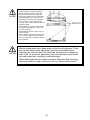
General Precautions
Follow Instructions: All operating and use instructions should be followed.
Attachments: Do not use attachments not recommended by the product manufacturer as they may cause hazards.
Accessories: Do not place this product on an unstable cart, stand, tripod, bracket, or table. The product may fall,
causing serious injury to a child or adult, and serious damage to the product. Use only with a cart, stand, tripod, bracket, or
table recommended by the manufacturer, or sold with the product. Any mounting of the product should follow the
manufacturer’s instructions, and should use only mounting accessories recommended by the manufacturer.
Moving the Product: This product should be moved with care. Quick stops, excessive force, and uneven surfaces
may cause the product to overturn.
Ventilation: Slots and openings in the cabinet are provided for ventilation, to ensure reliable operation of the product
and to protect it from overheating; these openings must not be blocked or covered. The openings should never be blocked
by placing the product in a built-in installation such as a bookcase or rack unless proper ventilation is provided or the
manufacturer’s instructions have been adhered to.
Power Sources: This product should be operated only from the type of power source indicated on the marking label.
If you are not sure of the type of power supply to your location, consult your local power company. For products intended
to operate from battery power or other sources, refer to the operating instructions.
Grounding or Polarization: This product is equipped with a three-wire grounding-type plug, a plug having a third
(grounding) pin. This plug will only fit into a grounding-type power outlet. This is a safety feature. If you are unable to
insert the plug into the outlet, contact your electrician to replace your obsolete outlet. Do not defeat the safety purpose of the
grounding-type plug.
Power Cord Protection: Power-supply cords should be routed so that they are not likely to be walked on or pinched
by items placed upon or against them, paying particular attention to cords at plugs, convenience receptacles, and the point
where they exit from the product.
Overloading: Do not overload wall outlets, extension cords, or integral convenience receptacles as this can result in
a risk of fire or electric shock.
Object and Liquid Entry: Never push objects of any kind into this product through openings as they may touch
dangerous voltage points or short-out parts that could result in a fire or electric shock. Never spill liquid of any kind on the
product.
Servicing: Do not attempt to service this product yourself as opening or removing covers may expose you to dangerous voltage or other hazards. Refer all servicing to qualified service personnel.
Damage Requiring Service: Unplug this product from the wall outlet and refer servicing to qualified service personnel under the following conditions:
a) If the power cord or plug is damaged;
b) If liquid has been spilled, or objects have fallen into the product;
c) If the product has been exposed to rain or water;
d) If the product does not operate normally when following the operating instructions. Adjust only those controls that
are explained in the operating instructions. An improper adjustment of other controls may result in damage and will
often require extensive work by a qualified technician to restore the product to its normal operation;
e) If the product has been dropped or damaged in any way;
f) When the product exhibits a distinct change in performance; this indicates a need for service.
Replacement Parts: When replacement parts are required, be sure the service technician has used replacements parts
specified by the manufacturer or that have the same characteristics as the original part. Unauthorized substitutions may
result in fire, electric shock, or other hazards.
2
Safety Check: Upon completion of any service or repairs to this product, ask the service technician to perform safety
checks to determine that the product is in proper operating condition.
Heat: The product should be situated away from heat sources such as radiators, heat registers, stoves, or other products (including amplifiers) that produce heat.
Lithium Battery- Dispose of batteries only in accordance with the battery manufacturer’s recommendations. Do not dispose in an open flame condition, since the battery may explode.
Cleaning: When cleaning the monitor glass, use water or glass cleaner and a soft cloth. Do not apply chemicals such
as benzine, thinner, etc.
Location: This an indoor game machine, DO NOT install it outside. To ensure proper usage, avoid installing indoors
in the places mentioned below:
• Places subject to rain/water leakage, or condensation due to humidity;
• In close proximity to a potential wet area;
• Locations receiving direct sunlight;
• Places close to heating units or hot air;
•In the vicinity of highly inflammable/volatile chemicals or hazardous matter;
• On sloped surfaces;
• In the vicinity of emergency response facilities such as fire exits and fire extinguishers;
• Places subject to any type of violent impact;
• Dusty places.
INSTALLATION PRECAUTIONS
• Verify the amperage of the branch circuit outlet before plugging in the power plug. Do not overload the circuit.
• Avoid using an extension cord. If one is required, use an extension cord of type SJT, 16/3 AWG
rated min. 120 VAC, 7A.
• Moving this unit requires a minimum clearance (of doors, etc.) of 32” (W) by 77” (H).
• For the operation of this machine, secure a minimum area of 32” (W) by 42”(D).
REGULATORY APPROVALS
This game has been tested and found to comply with the Federal Communications Commission Rules.
This device complies with Part 15 of the FCC Rules. Operation is subject to the following two conditions: (1) This
device may not cause harmful interference, and (2) this device must accept any interference received, including interference
that may cause undesired operation.
This game has been tested and listed by Underwriters Laboratories, Inc., to ANSI/UL22.
LISTED
UL
5K92
®
AMUSEMENT MACHINE
3
1 . PRECAUTIONS TO BE HEEDED FOR OPERATION
In order to prevent accidents, be sure to comply with the following points before and during operation.
PRECAUTIONS TO BE HEEDED FOR OPERATION BEFORE STARTING THE OPERATION
In order to avoid accidents, check the following before starting the operation:
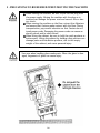
Check if all of the adjusters are in contact with the surface. If they are not,
the cabinet can move and cause an accident.
Do not climb on the product. Climbing on the product can cause falling
down accidents. To check the top portion of the product, use a step.
To avoid electric shock, check to see if door & cover parts are closed.
To avoid electric shock, short circuit and or parts damage, do not put the
following items on or in the periphery of the product:
Flower vases, flower pots, cups, water tanks, cosmetics, and receptacles/
containers/vessels containing chemicals and water.
To avoid injury, be sure to provide sufficient space by considering the
potentially crowded situation at the installation location. Insufficient installation space can cause the player to come into contact with or hit others
and result in injury or trouble.
4
PRECAUTIONS TO BE HEEDED DURING OPERATION
To avoid injury and accidents, those who fall under the following catagories are not
allowed to play the game:
* Intoxidated persons
* Those who have high blood pressure or heart problems.
* Those who have experienced muscle convulsion or loss of consciousness when playing
video games, etc.
* Persons susceptible to motion sickness.
* Persons whose acts runs counter to the products warning displays.
* Instruct those who wear high-heeled shoes to refrain from
playing the game by explaining that playing the game with highheeled showes is very dangerous and likely to cause a potentially
hazardous situation.
To avoid electric shock and short circuit, do not allow customers to put hands and fingers
or extraneous matter in openings of the product or small openings in or around doors.
To avoid electric shock and short circuit, do not allow the customers to unplug the power
plug without a justifiable reason.
Although this product has the accident preventive covering attached to potentially hazardous places where hand and fingers could be caught, small children are unable to perceive
hazards. Use care so that small children do not come close to the product when in play.
Immediately stop such violent acts as hitting and kicking the product. Such violent acts can
cause parts damage and/or falling down, resulting in injury due to fragments and falling
down.
5
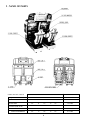
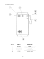
2 . NAME OF PARTS
GAME SPECIFICATIONS
WIDTH
LENGTH
HEIGHT
~ 1250 LBS.
All measurements are in inches
Weight-DURING SHIPPING
WEIGHT
BILLBOARD
64”
X
27”
X
24”
105 LBS.
COCKPIT (PER SEAT)
33”
X
66”
X
61”
514 LBS.
COIN CHUTE TOWER
12.5”
X
18”
X
23”
33 LBS.
66”
X
68”
X
85”
1172 LBS.
WHEN ASSEMBLED
6
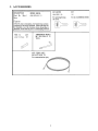
3 . ACCESSORIES
7
THE SHIPMENT METHOD DESCRIBED BELOW ONLY
APPLIES TO ‘MODEL 3’ BOARDS CONTAINED IN THE
FOLLOWING GAMES:
LOST WORLD, VIRTUA FIGHTER 3, SUPER GT, SEGA BASS FISHING, STRIKER 2
HARLEY DAVIDSON, RALLY 2
!!NEVER SHIP MODEL 3 GAME BOARDS
OUTSIDE OF CAGE!!
CARTON BOX
601-8928 (1)
Used for transporting the GAME BOARD.
{SUPPLIED WITH YOUR GAME}
DO NOT SHIP GAME BOARD WITHOUT
THIS BOX AS IT MAY DAMAGE THE GAME
BOARD AND VOID YOUR WARRANTY.
“CHECK SIDE” Display
FILTER BOARD
NO OTHER GAMES BOARDS ARE TO BE SHIPPED IN THE CAGE AS
THEY MAY BE DAMAGED BEYOND REPAIR. PLEASE SHIP THEM
WITHOUT CAGE PROPERLY PROTECTED DURING SHIPPING.
8
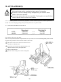
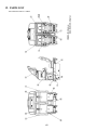
4 . ASSEMBLING AND INSTALLATION
Assembling should be performed as per this manual. Since this is a
complex machine, erroneous assembling may cause damage to the
machine, or malfunctioning to occur.
When assembling, be sure to perform work by plural persons.
Depending on the assembly work, there are some cases in which
performing the work by a single person can cause personal injury or
parts damage.
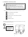
When carrying out the assembly work, follow the procedure in the following 7-item sequence:
1
ASSY OF THE REAR CABI (COCKPIT)
2
ASSY OF BILLBOARD
3
SECURING IN PLACE (ADJUSTER ADJUSTMENT)
4
POWER SUPPLY
5
ASSEMBLING CHECK
Note that the tools such as a phillips screwdriver and wrench for M16 hexagon bolt w/24 mm width
across flats are required for the assembly work.
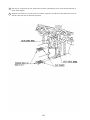
1
ASSY OF REAR CABI (COCKPIT)
Permanantly tightening
the hex bolts should
not be completed until
the leg levelers are
adjusted properly.
9
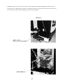
1 Place the two cockpits side by side. Position the 1P cabinet, which has the power cord at the left hand side, as
shown in the diagram.
2 Install the coin chute tower in between the two cabinets. Open the coin chute door and cashbox door to secure
with the 4 hex bolts from are fastened temporarily.
10
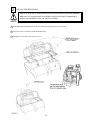
2
ASSY OF THE BILLBOARD
Due to its large size, it is very difficult for one person alone to install the billboard,
Make sure 2 or more persons are available to perform this work. Attempting to
perform the installation alone can cause an accident.
1 Mount Billboard on tbothcabinets and secure with the 4 hexgaonal bolts for each cabinet.
2 Connect all of the 4 connectors inside the Billboard box.
3 Install Wire Cover L&R with 5 screws for each.
11
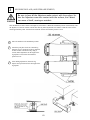
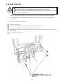
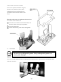
3
SECURING IN PLACE (ADJUSTER ADJUSTMENT)
Be sure to have all the Adjusters make contact with the surface. Unless the Adjusters come into contact with the surface, the Cabinet
can move of itself, causing an accident.
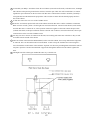
This machine has 8 each of casters and adjusters (shown below). When the installation position is determined, cause
the adjusters to come into contact with the floor directly, make adjustments in a manner so that the casters will be
raised approximately 5mm. from the floor and make sure that the machine position is level.
1
Move the machine to the installation position.
2
Attach the joint plate for the two internal leg
adjusters prior to causing all of the leg adjusters
to make contact with the floor. By using a
wrench, make adjustments in the height of the
leg adjusters to ensure that the machine's
position is level.
3
After making adjustments, fasten the leg
adjuster nut upward and secure the height of the
leg adjuster.
12
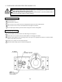
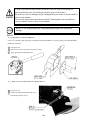
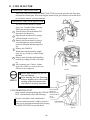
4
POWER SUPPLY
Ensure that the power cord is not exposed on the surface (passage,
etc.). If exposed, they can be caught and are susceptible to damage.
If damaged, the cord can cause an electric shock or short circuit.
Ensure that the wiring position is not in the customer's passage way
or the wiring has protective covering.
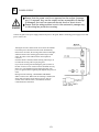
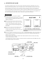
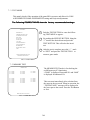
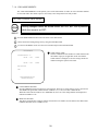
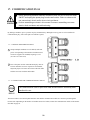
Connect the game to the power supply and turn on power to the game. Before connecting power supply be sure that
power switch is off
Turning the AC unit’s main switch on will cause the machine
to start the power check and network check automatically.
In the Power On check, the steering wheel turns left and right,
and then returns to the centering position and stops. In this
check, the values of the VR inside the control panel are
corrected.
Until this check is finished, and the steering wheel stops, do
not touch the steering wheel or play the game.
If you do, the steering reaction during the game (reaction at
the time of course-out or crash) can not be obtained correctly.
In the case of an abnormal reaction during the game, turn
power on again from the beginning and complete the power on
check.
During Network checking, “NETWORK CHECKING”
flashes on the screen. When network checking is finished, the
demo mode will appear on the monitor screen. After 10
seconds, if the network check is not finished, check the
communications connections.
13
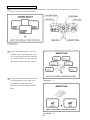
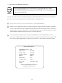
5
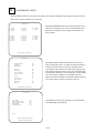
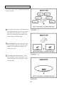
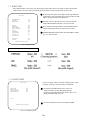
ASSEMBLING CHECK
The TEST MENU allows for each part of the cabinet to be checked, the Monitor to be adjusted, and the coin and
game related various functions to be performed.
MEMORY TEST
IC ** GOOD
IC ** GOOD
IC ** GOOD
IC ** GOOD
IC ** GOOD
IC ** GOOD
IC ** GOOD
IC ** GOOD
IC ** GOOD
IC ** GOOD
IC ** GOOD
IC ** GOOD
IC ** GOOD
IC ** GOOD
IC ** GOOD
IC ** GOOD
IC ** GOOD
IC ** GOOD
IC ** GOOD
IC ** GOOD
IC ** GOOD
IC ** GOOD
Selecting the MEMORY TEST on the test mode menu screen
causes the on-board memory to be tested automatically. The
game board is satisfactory if the display beside each IC No.
shows GOOD.
PRESS TEST BUTTON TO EXIT
INPUT TEST
STEERING WHEEL
GAS PEDAL
BRAKE PEDAL
**H
**H
**H
SHIFT UP
SHIFT DOWN
VIEW 1 (ZOOM IN)
VIEW 2 (ZOOM OUT)
OFF
OFF
OFF
OFF
START
OFF
COIN CHUTE #1
COIN CHUTE #2
OFF
SERVICE-SW
TEST-SW
OFF
OFF
Selecting the INPUT TEST on the menu screen in the test
mode to display the screen on which each SW and Volume is
tested. Press each switch. (To check the Coin SW, insert a
Coin from the inlet with the Coin Chute Door being opened.)
If the display beside each switch is ON, the switch and wiring
connection are satisfactory. Check the display of each Volume
value. The Volume could have an irregularity caused by
differences between machines and vibration during transportation. Set the Volume values by referring to Section ?
PRESS TEST BUTTON TO EXIT
OUTPUT TEST
START LAMP
VIEW 1 (ZOOM IN) LAMP
VIEW 2 (ZOOM OUT) LAMP
LEADER LAMP
CENTERING LEVEL
OFF
OFF
OFF
OFF
OFF
In the output test mode, carry out lamp test to ascertain that
each lamp lights up satisfactorily.
>EXIT
SELECT WITH SERVICE BUTTON
PRESS TEST BUTTON TO EXIT
14
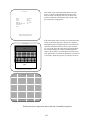
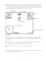
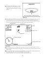
SOUND TEST
EFFECT
:
VOICE
:
B.G.M.
:
SPEAKER
:
BGM VOLUME LEVEL
SOUND OFF
SE_CHECK1
VO_30
BM_ADV1
VO_FRONT
9/15
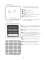
In the TEST mode, selecting SOUND TEST causes the
screen, on which sound related BD and wiring connections are tested, to be displayed. be sure to check if the
sound is satisfactorily emitted from each of speaker and
the sound volume is appropriate.
>EXIT
SELECT WITH SERVICE BUTTON
PRESS TEST BUTTON TO EXIT
C.R.T. TEST 1/2
12345678901234567890123456789012123456789012
12345678901234567890123456789012123456789012
12345678901234567890123456789012123456789012
12345678901234567890123456789012123456789012
12345678901234567890123456789012123456789012
12345678901234567890123456789012123456789012
12345678901234567890123456789012123456789012
12345678901234567890123456789012123456789012
12345678901234567890123456789012123456789012
RED
12345678901234567890123456789012123456789012
123456789012345678901234567890121234567
12345678901234567890123456789012123456789012
123456789012345678901234567890121234567
123456789012345678901234567890121234567
123456789012345678901234567890121234567
123456789012345678901234567890121234567
123456789012345678901234567890121234567
123456789012345678901234567890121234567
GREEN
123456789012345678901234567890121234567
123456789012345678901234567890121234567
123456789012345678901234567890121234567
123456789012345678901234567890121234567
1234567890123456789012345678
1234567890123456789012345678
1234567890123456789012345678
1234567890123456789012345678
BLUE
1234567890123456789012345678
1234567890123456789012345678
1234567890123456789012345678
1234567890123456789012345678
In the TEST mode menu, selecting C.R.T. TEST allows the
screen (on which the projector is tested) to be displayed.
Although the projector adjustments have been made at the
same time of shipment from the factory, color deviation,
etc., may occur due to the effect caused by geomagnitism,
the location building’s steel frames and other game machines in the periphery. By watching the test mode screen,
make judgement as to whether an adjustment is needed. If it
is neccessary, adjust the projector by refering to Section 9.
WHITE
PRESS TEST BUTTON TO CONTINUE
1234567890123456789012345678
1234567890123456789012345678
1234567890123456789012345678
1234567890123456789012345678
1234567890123456789012345678
1234567890123456789012345678
1234567890123456789012345678
1234567890123456789012345678
1234567890123456789012345678
1234567890123456789012345678
1234567890123456789012345678
1234567890123456789012345678
1234567890123456789012345678
1234567890123456789012345678
1234567890123456789012345678
1234567890123456789012345678
1234567890123456789012345678
1234567890123456789012345678
1234567890123456789012345678
1234567890123456789012345678
1234567890123456789012345678
1234567890123456789012345678
1234567890123456789012345678
1234567890123456789012345678
1234567890123456789012345678
C.R.T. TEST 2/2
PRESS TEST BUTTON TO CONTINUE
Perform the above inspections also at the time of monthly inspection.
15
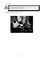
5 . PRECATIONS TO BE HEEDED WHEN MOVING THE MACHINE
When moving the machine, be sure to pull out the plug from
the power supply. Moving the machine with the plug as is
inserted can damage the power cord and cause a fire or electric shock.
When moving the machine on the floor, retract the Adjusters
and ensure that Casters make contact with the floor. During
transportation, pay careful attention so that Casters do not
tread power cords. Damaging the power cords can cause an
electric shock and/or short circuit.
When lifting the cabinet, be sure to hold the catch portions or
bottom part. Lifting the cabinet by holding other portions can
damage parts and installation portions, due to the empty
weight of the cabinet, and cause personal injury.
Use care when handling glass made parts. When the glass is damaged, fragments of glass can cause injury
16
6 . CONTENTS OF GAME
The following explanations apply to the case the product is functioning satisfactorily. Should there be any moves
different from the following contents, some sort of faults may have occured. Immediately look into the cause of the
fault and eliminate the cause thereof to ensure satisfactory operation. During the Advertise mode, the Billboard’s
Decoration Lamp lights up periodically. When the machine is energized, the Billboard’s Fluorescent Lamp is always lit.
The Steering Wheel repeats centering action periodically. Automatic centering will apply to the Steering Wheel if it is
not centered. During the Advertise Mode, sound is emitted fromt e Speaker beside the Monitor.
HOW TO PLAY
1 Get in the machine. the seat position is adjustable
forward and backward. Facing the monitor, you will find
the Lever on the lower right-hand side. Pull the Lever to
adjust the seat position.
2 Insert a coin(s). Insert one play worth of coins to have
the Select Mode appear. Up to 9 credits can be counted
at a time. Coins inserted after counting 9 will not be
counted or rejected. Credits will not be displayed after
Select Mode.
3 When a coin is inserted in one of the linked seats, the
monitor(s) of the other seat(s) will be in the entry
acceptance mode and countdown starts. For entry, insert
a coin during countdown.
4 In the case of 1P play, in the SELECT mode, choose either of CHAMPIONSHIP MODE or PRACTICE MODE. Turn
the Steering Wheel to select and confirm by stepping on the Accelerator. In the communication play, PRACTICE
MODE is selected compulsorily.
When the SELECT mode is displayed, countdown starts. When countdown reaches 0, the course and car being
selected will automatically be decided.
After stepping on the Accelerator to confirm, you will proceed to the next SELECT mode in the middle of the countdown by further stepping on the Accelerator.
17
WHEN PLAYING IN TH ECHAMPIONSHIP MODE
Note: In the interactive play, CHAMPIONSHIP MODE
can not be selected.
1 The car select mode appears. Select from among 6
types. Depending on the type of car, your operating sensation may somewhat vary. Choose the
desired car by turning the Steering Wheel, and
confirm with the Accelerator Pedal.
2 TRANSMISSION SELECT mode appears. Turn
the Steering Wheel and select either AT (AUTOMATIC) or MT (MANUAL, 4 SHIFTS), and
confirm with pedal.
3 The NAME ENTRY MODE appears. Turn the
Steering Wheel to choose input characters, and
confirm with pedal. After inputing the 3 characters, game starts.
18
4 On the upper left portion of the screen, total time & lap time are displayed. The remaining time is shown at the top
center and navigation icon is seen at the loer part of the top center. on the upper right-hand side, the present player’s
position as well as the stage’s top 3 times are displyed. the lower left portion shows tachometer and shift speed. the
lower right-hand portion indicates the selected car and the driver’s name entered.
5 After game start, time decreases. Passing a mid-course checkpoint increases time and game continues. Failing to
pass the checkpoint within the time limit causes game over. Finishing the GOAL in each stage will let you proceed
to the next stage.
6 In the Championship mode, you proceed starting from DESERT (novice) sequentially to MOUNTAIN (intermediate), SNOWY (expert) with one lap for each, and RIVIERA (expert) with 2 laps.
7 Finishing the RIVIERA (expert) course results in GAME CLEAR and the game ends.
The Steering Wheel and the Cabinet will react depending on the road surface status and car condition during play. Press
the View Change Button to shift to a different view.
19
WHEN PLAYING IN THE PRACTICE MODE
1 The Course Select mode appears. Turn the Steering Wheel to select and confirm with pedal. In case of communication play, the course is selected by majority.
2
The Car Select Mode appears. Select from
among the 6 types. Depending on the type of
car, your operating sensation may somewhat
vary. Select the desired car with the Steering
Wheel. Step on the Accelerator to confirm.
3
The Transmission Select Mode appears. Turn
the Steering Wheel to choose either of AT
(AUTOMATIC) or MT (MANUAL, 4
SHIFTS), and confirm with the Accelerator
Pedal.
20
4 The NAME ENTRY MODE appears. Turn the
Steering Wheel to choose input characters, and
confirm with pedal. After inputing the 3 characters,
game start
5 On the upper left portion of the screen, total time & lap time are displayed. The remaining time is shown at the top
center and navigation icon is seen at the loer part of the top center. on the upper right-hand side, the present
player’s position as well as the stage’s top 3 times are displyed. the lower left portion shows tachometer and shift
speed. the lower right-hand portion indicates the selected car and the driver’s name entered.
6 After game start, time decreases. Passing a mid-course checkpoint increases time and game continues. Failing to
pass the checkpoint within the time limit causes game over. Finishing the GOAL in each stage will let you proceed
to the next stage.
7 In the Championship mode, you proceed starting from DESERT (novice) sequentially to MOUNTAIN (intermediate), SNOWY (expert) with 3 laps for each, and RIVIERA (expert) with 5 laps.
Finishing the RIVIERA (expert) course results in GAME CLEAR and the game ends.
21
7 . EXPLANATION OF TEST AND DATA DISPLAY
By operating the switch unit, periodically perform the tests and data check. When installing the machine intitally or
collecting cash, or when the machine does not function correctly, perform checking in accordance with the explanations
given in this section. The following shows tests and modes that should be utilized as applicable.
When you enter the test mode, the Handlebar and Bike Body are unlocked. Do not lean against
the BikeBody when you press the test button. Failure to observe this can cause violent falling
down accidents as the Bike Body will bank. When you finish the test mode, the handlebar and
Bike Body will be locked.
CAUTIONS TO BE HEEDED WHEN USING THE TEST MODE:
In the case where plural machines are linked for communication play, if even one seat enters
the test mode, all of the linked seats will enter the test mode. Therefore, if any one of the
linked machines is in play, use care so as not to use the test mode.
The contents of the setting changes made will not be effective unless the test mode is
finished in the test mode. When the setting is changed, be sure to “EXIT” in the menu mode.
Do not press the TEST BUTTON during network check at the time of turning the power on or
exiting from the test mode. If anyone of the linked machines uses the test mode during
network check, all other Seats will continue network checking. Cause all of the Seats to
reenter the test mode and then have all of the Seats exit from the test mode simultaneously.
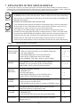
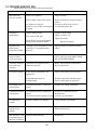
TABLE 7
EXPLANATION OF TEST MODE
ITEMS
DESCRIPTION
When the machine is installed, perform the following:
INSTALLATION 1. Check to see that each setting is as per standard setting made
at the time of shipment.
OF MACHINE
2. In the INPUT TEST mode, check each SW and VR.
3. In the OUTPUT TEST mode, check each of lamps.
4. In the MEMORY TEST mode, check ICs on the IC Board.
MEMORY
PERIODIC
SERVICING
CONTROL
SYSTEM
Choose MEMORY TEST in the MENU mode to allow the
MEMORY test to be performed. In this test, PROGRAM
RAMs, ROMs, and ICs on the IC Board are checked.
SECTIONS
7 - 10, 7 - 11
7-6
7-7
7 - 3, 7 - 4
7 - 3, 7 - 4
Periodically perform the following:
1. MEMORY TEST
2. Ascertain each setting.
3. In the INPUT TEST mode, test the CONTROL device
4. In the OUTPUT TEST mode, check each of lamps.
7 - 10, 7 - l1
1. In the INPUT TEST mode, check each SW and VR.
2. Adjust or replace each SW and VR.
3. If the problem can not be solved yet, check the CONTROL’s moves.
7-6
MONITOR
In the MONITOR ADJUSTMENT mode, check to see if the
MONITOR adjustment is appropriately made.
IC BOARD
1. MEMORY TEST
2. In the SOUND TEST mode, check the sound related ROMs.
DATA CHECK
Check such data as game play time and histogram to adjust the
difficulty level, etc
22
7-6
7-7
8
8
7-9
7-8
7 - 15
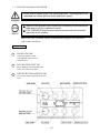
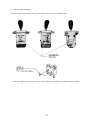
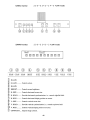
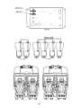
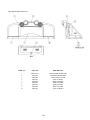
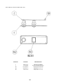
7 - 1 SWITCH UNIT AND COIN METER
Never touch places other than those specified. Touching places not
specified can cause electric shock and short circuit.
Adjust to the optimum sound volume by considering the environmental
requirements of the installation location.
If the COIN METER and the game board are electrically disconnected,
game play is not possible.
Open COIN CHUTE DOOR, and the switch unit shown appears. The function of
each switch is as follows:
SWITCH UNIT
1
SOUND VOLUME
Controls the speaker volume
of the right/left speakers on the
coin chute tower.
2
TEST BUTTON (TEST SW)
For the handling of the TEST BUTTON,
refer to the section on test mode.
3
SERVICE BUTTON (SERVICE SW)
Gives credits without registering on the coin
meter.
23
7 - 2 TEST MODE
This mainly checks if the operation of the game BD is accurate, and allows for COIN
ASSIGNMENTS/GAME ASSIGNMENTS setting and Projector adjustments.
The Following FIGURES/TABLES show the factory recommended settings.
TEST MENU
MEMORY TEST
1
Push the TEST BUTTON to cause the following TEST MENU to appear:
2
By pushing the SERVICE BUTTON, bring the
“>” mark to the desired item and press the
TEST BUTTON. This will select the item’s
test.
3
After the test is complete, move the “>” mark
to “EXIT” and press the TEST BUTTON to
return to game mode.
STEERING REACTION TEST
COCKPIT REACTION TEST
INPUT TEST
OUTPUT TEST
SOUND TEST
C.R.T. TEST
GAME ASSIGNMENTS
COIN ASSIGNMENTS
BOOKKEEPING
BACKUP DATA CLEAR
>EXIT
SELECT WITH SERVICE BUTTON
AND PRESS TEST BUTTON
FIG. 7.2 TEST MENU
7 - 3 MEMORY TEST
MEMORY TEST
IC ** GOOD
IC ** GOOD
IC ** GOOD
IC ** GOOD
IC ** GOOD
IC ** GOOD
IC ** GOOD
IC ** GOOD
IC ** GOOD
IC ** GOOD
IC ** GOOD
IC ** GOOD
IC ** GOOD
IC ** GOOD
IC ** GOOD
IC ** GOOD
IC ** GOOD
IC ** GOOD
IC ** GOOD
IC ** GOOD
IC ** GOOD
IC ** GOOD
The MEMORY TEST mode is for checking the
on-BD memeory IC functioning.
“GOOD” is displayed for normal ICs and “BAD”
is displayed for abnormal ICs
This test starts immediately after selection from
the menu in the test mode. When in execution, the
“TESTING NOW” message will be displayed at
the lower part to the screen. Press the Test Button
to Exit.
PRESS TEST BUTTON TO EXIT
FIG. 7.3 MEMORY TEST
24
7 - 4 STEERING REACTION TEST
This test allows Steering Wheel reaction mechanism to be
tested and eaction force to be set. Press the Service Button to
STEERING REACTION TEST
bring the arrow to the desitred item to be selected, and press the
CENTERING
RIGHT
LEFT
FORCE
>EXIT
OFF
OFF
OFF
OFF
Test Button to enter the selected item.
CENTERING
Press the Test Button or the Start Button to apply automatic
centering to Steering Wheel.
RIGHT
The Steering Wheel turns up to the RIGHT maximum value.
LEFT
The Steering Wheel turns up to the LEFT maximum value.
FORCE Adjusts the Steering Wheel’s reaction force.
PRESS TEST BUTTON TO CONTINUE
0/15 (minimum)<--->15/15 (maximum)
FIG. 7.4 STEERING REACTION TEST
This on-screen adjustment will be effective whent he Test Mode is exited. Turning power off while the on-screen
display is shown will have the pre-adjustment reaction force remain as it is.
25
7 -5 INPUT TEST
Select INPUT TEST to have the screen shown below appear and to observe the status of each switch and the
Control Panel’s each V.R. Value. Periodically check the status of each switch and V.R. on this screen.
By pressing each switch, if the display onthe right-hand side
of the name of each switch changes to ON from OFF, the SW
and the wiring connections are satisfactory.
INPUT TEST
STEERING WHEEL
GAS PEDAL
BRAKE PEDAL
**H
**H
**H
SHIFT UP
SHIFT DOWN
VIEW 1 (ZOOM IN)
VIEW 2 (ZOOM OUT)
OFF
OFF
OFF
OFF
START
HAND BRAKE
GEAR POSITION
OFF
OFF
N
COIN CHUTE #1
COIN CHUTE #2
OFF
SERVICE-SW
TEST-SW
OFF
OFF
To check CHUTE 1 & CHUTE 2 coin switches, open the
COIN CHUTE DOOR and insert a coin(s) in the slot.
Press either the TEST BUTTON or the START BUTTON +
VIEW CHANGE BUTTON to return to the test menu.
GEAR POSITION indicates which shift and SHIFT LEVER
is in. “N” means neutral.
PRESS TEST BUTTON TO EXIT
FIG. 7.5 INPUT TEST
THE APPROPRIATE VALUES OF EACH V.R.
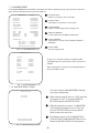
7 - 6 OUTPUT TEST
OUTPUT TEST
START LAMP
VIEW 1 (ZOOM IN)
VIEW 2 (ZOOM OUT)
DECORATION LAMP
Choose OUTPUT TEST to cause the following lower screen
to appear. In this test, check the status of each lamp.
OFF
OFF
OFF
OFF
Pressing the TEST BUTTON causes “ON” to be
displayed and the corresponding lamp lights up.
Pressing the TEST BUTTON again cuases “OFF” to be
displayed and the lamp goes off.
>EXIT
Press the test Button to return to the MENU MODE.
PRESS TEST BUTTON TO EXIT
FIG. 7.6 OUTPUT TEST
26
7 - 7 SOUND TEST
SOUND TEST
EFFECT
:
VOICE
:
B.G.M.
:
SPEAKER
:
BGM VOLUME LEVEL
SOUND OFF
SE_CHECK1
VO_30
BM_ADV1
VO_FRONT
9/15
>EXIT
This enables sound used in the game to be checked.
Sound related memory and each speaker are checked.
EFFECT:
Sound effects during game.
VOICE:
Voice of announcement and naration.
SPEAKER:
SE speaker check. Checking front/back and left/right is
possible.
BGM VOLUME LEVEL:
BGM sound level. 0/15 (low)~15/15 (high)
SELECT WITH SERVICE BUTTON
PRESS TEST BUTTON TO EXIT
FIG. 7.7 SOUND TEST
Bring the “>” to EXIT and press the TEST BUTTON to
return to the MENU MODE.
7 - 8 C.R.T. TEST
C.R.T. TEST 1/2
12345678901234567890123456789012123456789012
12345678901234567890123456789012123456789012
12345678901234567890123456789012123456789012
12345678901234567890123456789012123456789012
12345678901234567890123456789012123456789012
12345678901234567890123456789012123456789012
12345678901234567890123456789012123456789012
12345678901234567890123456789012123456789012
12345678901234567890123456789012123456789012
12345678901234567890123456789012123456789012
RED
12345678901234567890123456789012123456789012
12345678901234567890123456789012123456
12345678901234567890123456789012123456
12345678901234567890123456789012123456
12345678901234567890123456789012123456
12345678901234567890123456789012123456
12345678901234567890123456789012123456
12345678901234567890123456789012123456
12345678901234567890123456789012123456
GREEN
12345678901234567890123456789012123456
12345678901234567890123456789012123456
12345678901234567890123456789012123456
12345678901234567890123456789
12345678901234567890123456789
12345678901234567890123456789
12345678901234567890123456789
12345678901234567890123456789
BLUE
12345678901234567890123456789
12345678901234567890123456789
12345678901234567890123456789
WHITE
PRESS TEST BUTTON TO CONTINUE
1234567890123456789012345678
1234567890123456789012345678
1234567890123456789012345678
1234567890123456789012345678
1234567890123456789012345678
1234567890123456789012345678
1234567890123456789012345678
1234567890123456789012345678
1234567890123456789012345678
1234567890123456789012345678
1234567890123456789012345678
1234567890123456789012345678
1234567890123456789012345678
1234567890123456789012345678
1234567890123456789012345678
1234567890123456789012345678
1234567890123456789012345678
1234567890123456789012345678
1234567890123456789012345678
1234567890123456789012345678
1234567890123456789012345678
1234567890123456789012345678
1234567890123456789012345678
1234567890123456789012345678
1234567890123456789012345678
Select C.R.T. TEST to cause the MONITOR to display the
screen shown left, allowing MONITOR adjustment status
to be checked.
Periodically check the MONITOR adjustment status on
this screen.
The screen (1/2) enables color adjustment check to be
performed. The color bar of each of the 4 colors, i.e.,red,
green, blue, and white, is the darkest at the extreme left and
becomes brighter towards the extreme right.
Press the TEST BUTTON to shift to the next screen (2/2).
The screen (2/2) allows screen size and distortion to be
tested.
C.R.T. TEST 2/2
Check if the CROSSHATCH FRAME LINE goes out of
the screen and if the crosshatch lines are distorted.
Press the TEST BUTTON to return to the MENU mode.
PRESS TEST BUTTON TO EXIT
FIG. 7.8 C.R.T. TEST
27
7 - 9 GAME ASSIGNMENTS
Selecting the GAME ASSIGNMENTS in the MENU mode causes the present game settings
to be displayed and also the game settings changes (game difficulty, etc.) can be made. Each
item displays the following content.
SETTING CHANGE PROCEDURE
Setting changes cannot be stored unless the TEST BUTTON is pressed
while the arrow is on EXIT.
1
Press the SERVICE BUTTON to move the “>” to the desired item.
2
Choose the desired setting change item by using the TEST BUTTON.
3
To return to the MENU mode, move the arrow to EXIT and press the TEST BUTTON.
GAME ASSIGNMENTS
ADVERTISE SOUND
ON
DIFFICULTY
NORMAL
GAME MODE
NORMAL
DEFAULT VIEW
DRIVER
SPEED
KM/H
DISPLY URL
OFF
CABINET TYPE
TWIN
LINK TYPE
MASTER (CAR1)
ADVERTISE SOUND
Determines wether ADVERTISE SOUND is to
be emitted or not by the setting to ON when
emitting it and to OFF when not emitting it.
GAME DIFFICULTY
Sets the Game Difficulty in 5 catagories from 1 to
8. The greater the number is, the higher the
difficulty level becomes. Alternately it may
display each catagory by name;
Very Easy, Easy, Normal, Hard, Very Hard
>EXIT
SELECT WITH SERVICE BUTTON
DISPLAY URL
Web Page Address indication during advertise.
AND PRESS TEST BUTTON
ENGINE VOLUME
Engine Volume adjustment
CABINET TYPE
Set to DELUXE or STANDARD as applicable. Setting to wrong type can causefailure be sure to
set correctly. (i.e. In communication Play Race Leader Lamp does not light up/flash/light out.
The Cabinet appearing in the operation explanation mode differs from the type used.)
GAME MODE
Setting of Laps.
NORMAL (normal lap setting)
SPECIAL (special setting for more laps-A long-time game mode for for events etc..)
The Following FIGURES/TABLES show the factory recommended settings.
28
7 - 10 COIN ASSIGNMENTS
The “COIN ASSIGNMENTS” mode permits you to set the start number of credits, as well as the basic numbers
of coins and credits. This mode expresses “how many coins correspond to how many credits.”
SETTING CHANGE PROCEDURE
Setting changes cannot be stored unless the TEST BUTTON is pressed
while the arrow is on EXIT.
1
Press the SERVICE BUTTON to move the arrow to the desired item.
2
Choose the desired setting change item by using the TEST BUTTON.
3
To return to the MENU mode, move the arrow to EXIT and press the TEST BUTTON.
COIN ASSIGNMENTS
COIN/CREDIT SETTING
#12
CHUTE#1
1 COIN
1 CREDIT
CHUTE#2
1 COIN
1 CREDIT
COIN CHUTE TYPE
Sets the combination of the number of COIN CHUTEs and
the number of players as applicable. In the case that the
COIN CHUTE is changed, be sure the setting is made in a
manner meeting the replaced coin chute.
MANUAL SETTING
>EXIT
SELECT WITH SERVICE BUTTON
AND PRESS TEST BUTTON
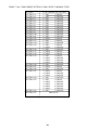
COIN/CREDIT SETTING
Sets the CREDITS increase increment per coin insertion. There are 27 setings from #1 to #27, expressed in
XX CREDIT as against XX COINS inserted. (TABLE 7.11a, 7.11b) #27 refers to FREE PLAY.
When the COIN CHUTE TYPE is set to INDIVIDUAL, there are some setting numbers not displayed as
indicated in TABLE 7.11b.
MANUAL SETTING
This allows credit increase setting as against coin insertion to be further set in the manner finer than COIN/
CREDIT SETTING (refer to TABLE 7.11c).
29
TABLE 7.10a COIN/CREDIT SETTING (COIN CHUTE COMMON TYPE)
SETTING
SETTING #1
SETTING #2
SETTING #3
SETTING #4
SETTING #5
SETTING #6
SETTING #7
SETTING #8
SETTING #9
SETTING #10
SETTING #11
SETTING #12
SETTING #13
SETTING #14
SETTING #15
SETTING #16
SETTING #17
SETTING #18
SETTING #19
SETTING #20
SETTING #21
SETTING #22
SETTING #23
SETTING #24
SETTING #25
SETTING #26
SETTING #27
FUNCTIONING OF CHUTE#1
1 COIN
1 CREDIT
1 COIN
2 CREDITS
1 COIN
3 CREDITS
1 COIN
4 CREDITS
1 COIN
5 CREDITS
1 COIN
2 CREDITS
1 COIN
5 CREDITS
1 COIN
3 CREDITS
1 COIN
4 CREDITS
1 COIN
5 CREDITS
1 COIN
6 CREDITS
2 COINS
1 CREDIT
1 COIN
1 CREDIT
1 COIN
2 CREDITS
1 COIN
1 CREDIT
2 COINS
3 CREDITS
1 COIN
3 CREDITS
3 COINS
1 CREDIT
4 COINS
1 CREDIT
1 COIN
1 CREDIT
2 COINS
2 CREDITS
3 COINS
3 CREDITS
4 COINS
5 CREDITS
1 COIN
5 CREDITS
5 COINS
1 CREDIT
1 COIN
2 CREDITS
2 COINS
1 CREDIT
4 COINS
2 CREDITS
5 COINS
3 CREDITS
1 COIN
3 CREDITS
1 COIN
1 CREDIT
2 COINS
2 CREDITS
3 COINS
3 CREDITS
4 COINS
4 CREDITS
5 COINS
6 CREDITS
1 COIN
1 CREDITS
FREE PLAY
30
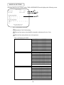
MANUAL SETTING
Selecting MANUAL SETTING in the COIN ASSIGNMENTS mode displays the following screen.
MANUAL SETTING
COIN TO CREDIT
1 COIN
BONUS ADDER
NO BONUS ADDER
1
1 CREDIT
2
COIN CHUTE #1 MULTIPLIER
1 COIN COUNTS AS 1 COIN
COIN
1
2
3
CREDIT 1
2
3
4
4
5
5
6
6
7
7
8
8
9
9
COIN CHUTE #2 MULTIPLIER
1 COIN COUNTS AS 1 COIN
COIN
1
2
3
CREDIT 1
2
3
4
4
5
5
6
6
7
7
8
8
9
9
3
>EXIT
SELECT WITH SERVICE BUTTON
AND PRESS TEST BUTTON
FIG. 7.10sb MANUAL SETTING
1 Determines Coin/Credit setting.
2 This sets how many coins should be inserted to obtain one Service Coin.
3 This sets how many tokens one coin represents.
Table 7.10c MANUAL SETTING
COIN TO CREDIT
1 COIN
2 COINS
3 COINS
4 COINS
5 COINS
6 COINS
7 COINS
8 COINS
9 COINS
BONUS ADDER
NO BONUS ADDER
2 COINS GIVE 1 EXTRA COIN
3 COINS GIVE 1 EXTRA COIN
4 COINS GIVE 1 EXTRA COIN
5 COINS GIVE 1 EXTRA COIN
6 COINS GIVE 1 EXTRA COIN
7 COINS GIVE 1 EXTRA COIN
8 COINS GIVE 1 EXTRA COIN
9 COINS GIVE 1 EXTRA COIN
COIN CHUTE MULTIPLIER
1 COIN COUNTS AS 1 COIN
1 COIN COUNTS AS 2 COINS
1 COIN COUNTS AS 3 COINS
1 COIN COUNTS AS 4 COINS
1 COIN COUNTS AS 5 COINS
1 COIN COUNTS AS 6 COINS
1 COIN COUNTS AS 7 COINS
1 COIN COUNTS AS 8 COINS
1 COIN COUNTS AS 9 COINS
31
1 CREDIT
1 CREDIT
1 CREDIT
1 CREDIT
1 CREDIT
1 CREDIT
1 CREDIT
1 CREDIT
1 CREDIT
7 - 11 BOOKKEEPING
Choosing BOOKKEEPING in the MENU mode displays the data of operating status up to the present are shown on 2
pages. Press the TEST BUTTON to proceed to PAGE 2/2.
BOOKKEEPING
PAGE1/2
COIN CHUTE #1
COIN CHUTE #2
TOTAL COINS
XXXXXXXXXXX
XXXXXXXXXXX
XXXXXXXXXXX
COIN CREDITS
SERVICE CREDITS
TOTAL CREDITS
XXXXXXXXXXX
XXXXXXXXXXX
XXXXXXXXXXX
NUMBER OF GAMES
XXXXXXXXXXX
TOTAL
TIME
PLAY
TIME
AVERAGE PLAY
LONGEST PLAY
SHORTEST PLAY
XDXXHXXMXXS
XDXXHXXMXXS
XXMXXS
XXMXXS
XXMXXS
TIME
TIME
TIME
TIME HISTOGRAM
0M 0S - 1M59S--------------->XXXXXXX
2M 0S - 2M59S--------------->XXXXXXX
OVER 6M30S----------------->XXXXXXX
PRESS TEST BUTTON TO CONTINUE
FIG. 7.11a BOOKKEEPING (1/2)
COIN CHUTE#*:
Number of coins put in each Coin Chute.
TOTAL COINS:
Total number of activations of Coin Chutes.
COIN CREDITS:
Number of credits registered by inserting coins.
SERVICE CREDITS:
Credits registered by the SERVICE BUTTON.
TOTAL CREDITS:
Total number of credits (COIN CREDITS+SERVICE
CREDITS).
TOTAL TIME:
The total energized time.
BOOKKEEPING PAGE 2/2
CAR SELECT
IMPREZA
STRATIOS
COROLLA
ESCORT
LANCER
PEUGEOT
XXXXXXX
XXXXXXX
XXXXXXX
XXXXXXX
XXXXXXX
XXXXXXX
When in the PAGE 2/2 mode, press the TEST BUTTON to
return to the MENU mode.
TRANSMISSION SELECT
AUTOMATIC
MANUAL
On page (2/2), each play frequency is displayed. When
setting difficulty levels, the frequency can be refered to as a
standard.
XXXXXXX
XXXXXXX
PRESS TEST BUTTON TO EXIT
FIG. 7.11b BOOKKEEPING (2/2)
7 - 12 BACKUP DATA CLEAR
Clears the contents of BOOKKEEPING and high
score player ranking entry.
BACKUP DATA CLEAR
YES (CLEAR)
>NO (CANCEL)
When clearing, bring the arrow to “YES” and when
not clearing, to “NO”, by using the SERVICE
BUTTON, and push the TEST BUTTON.
When the data has been cleared, “COMPLETED”
will be displayed. Bring the arrow to “NO” and
press the TEST BUTTON to cause the MENU
mode to return on to the screen.
Note that the contents of the GAME SETTING,
COIN SETTING, and BOARD SETTING are not
affected by BACKUP DATA CLEAR operation.
SELECT WITH SERVICE BUTTON
PRESS TEST BUTTON TO EXIT
FIG. 7.12 BACKUP DATA CLEAR
32
8. HANDLE MECHA
In order to prevent an electric shock and short circuit, be sure to turn power off
before performing work by touching the interior parts of the product.
Be careful so as not to damage wirings. Damaged wiring can cause an electric shock
or short circuit accident.
In the test mode, if the steering whell’s VR variations are not within the allowable range, the VR installation
position adjustments or VR replacement is needed. Also, be sure to apply grease to the VR gear portion once
every 3 months.
8 - 1 REMOVING THE CONTROL PANEL
1
Turn the power switch off.
2
Remove a total of 4 tamperproof screws from both sides of the control panel’s front.
3
Remove the two tamperproof screws fromthe underside of the control panel.
4
Wiring connectors are connected inside the control panel. Carefully draw the control panel in a mnner so as not to
damage wiring.
5
Disconnect the wiring connector.
33
8 - 2 REPLACING AND ADJUSTING THE HANDLE’S VR
Never touch places other than those specified. Touching places not specified can
cause electric shock and/or short circuit.
After the replacement or adjustment of the VR, be sure to set the variable value of
the VR in the test mode’s Volume Setting.
REPLACING THE VOLUME
1
Turn off the power.
2
Disconnect the connector.
3 Take out the 2 screws which secure the volume Bracket and remove the Volume Bracket.
4
Take out the 2 screws to remove the Volume Gear and replace the Volume.
5 After replacing the Volume, perform Volume setting in the Volume Setting Mode.
ADJUSTING THE VOLUME
1
In the Test Mode, have the Volume value indicating screen displayed.
2
Loosen the 2 screws which secure the Volume Bracket to disengage Gear Mesh.
3 With the Steering Wheel in the centering position, cause gears to be engaged in the manner so that the Volume
Shaft is in the status shown below.
4
Fasten screws which secure the Volume Bracket.
5
Perform Volume setting as per the Volume Setting Mode.
34
8 - 3 GREASING
Never touch places other than those specified. Touching places not specified can
cause electric shock and/or short circuit.
After the replacement or adjustment of the VR, be sure to set the variable value of
the VR in the test mode’s Volume Setting.
Apply greasing to the Volume gear mesh portion every 3 months.
For spray greasing, use Grease Mate (Part No. 090-0066).
35
9. SHIFT LEVER
In order to prevent electric shock and short circuit, be sure to turn off the power
before performing work on the interior parts of the product.
Be careful not to damage wiring. Damaged wiring can cause electric shock or short
circuit.
Do not touch places other than those specified. Touching places other than those
specified can cause an electric shock or short circuit accident.
If the Shift Lever operation is not satisfactory, remove the Shift Lever in the following procedure and replace the
microswitch.
9 - 1 REMOVING THE SHIFT LEVER
1
Turn Power off.
2
Take off the 4 screws and remove SHIFT COVER A.
3 Take out the 4 SPECIAL BOLTS and pull the SHIFT LEVER UNIT upward by paying careful attention so as not
to damage the wiring.
4
Disconnect the 2 connectors to allow the unit to be removed.
36
9 - 2 SWITCH REPLACEMENT
Each microswitch is secured with 2 screws. Remove the 2 screws and replace the Microswitch.
After replacing the Switch, check to see if the switch is inputted as per Shift Lever operation in the Test Mode.d
37
10. ACCEL & BRAKE(S)
In order to prevent an electric shock and short circuit, be sure to turn power off
before performing work by touching the interior parts of the product.
Be careful so as not to damage wirings. Damaged wiring can cause an electric
shock or short circuit accident.
Do not touch places other than those specified. Touching places not specified can
cause an electric shock or short circuit accident.
If Accel and Brake operation is not satisfactory, adjustment of Volume installation position or Volume replacement is
needed. Also, be sure to apply greasing to the gear mesh portion once every three months.
10 - 1 ADJUSTING AND REPLACING THE V.R.
Check Volume values in the Test Mode.
Since work is performed inside the energized cabinet, be very careful so as not to touch undesignated portions. Touching places not specified can cause an electric shock or short circuit.
1
Take out the 2 truss screws and remove the Front Cover
from the Accel. & Brake unit.
2
Loosen the screw which secures the Potentiobase, and
adjust the Volume Value by moving the Base.
3
Secure the Potentiobase.
4
Perform Volume setting in the Volume Setting Mode.
38
Check Volume values in the Test Mode.
Since work is performed inside the energized
cabinet, be very careful so as not to touch
undesignated portions. Touching places not
specified can cause an electric shock or short
circuit.
1
Take out the 2 truss screws and remove the Front Cover
from the Accel. & Brake unit.
2
Loosen the screw which secures the Potentiobase, and
adjust the Volume Value by moving the Base.
3
Secure the Potentiobase.
4
Perform Volume setting in the Volume Setting Mode.
10 - 2 GREASING
Be sure to use designated grease. Using undesignated grease can
cause parts damage.
Once every 3 months, apply greasing to the Spring and Gear Mesh portion. For spray greasing, use GREASE MATE
(PART No. 090-0066).
39
In order to prevent an electric shock and short circuit, be sure to turn power off
before performing work byt ouching the interior parts of the product.
Be careful so as not to damage wirings. Damaged wiring can cause an electric shock or
short circuit accident.
Do not touch places other than those specified. Touching places not specified can
cause an electric shock or short circuit accident.
Be sure to use designated grease. Using undesignated grease can cause parts
damage.
10 - 3 GREASING TO THE HANDBRAKE
Once every 3 months, apply greasing to the Spring inside the Hand Brake. For spray greasing, use GREASE MATE
(PART No. 090-0066)
1
Turn power off.
2
Take out the 9 screws and remove the Side Cover B.
3
Apply greasing to the Spring Portion.
10 - 4 REPLACING THE HAND BRAKE MICROSWITCH
1 Turn power off.
2 Replace the Microswitch inside Side Cover
B by taking out the 2 screws.
40
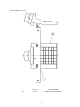
11 . COIN SELECTOR
HANDLING THE COIN JAM
If the coin is not rejected when the REJECT BUTTON is pressed, open the coin chute door
and open the selector gate. After removing the jammed coin, put a normal coin in and check
to see that the selector correctly functions.
CLEANING THE COIN SELECTOR
1
2
3
4
5
6
GATE
The coin selector should be cleaned
once every 3 months. When cleaning,
follow the procedure below:
Turn the power for the machine OFF.
Open the coin chute door.
Open the gate and dust off by using a
soft brush (made of wool, etc.).
Remove and cleen smears by using a
soft cloth dipped in water or diluted
chemical detergent and then squeezed
dry.
Remove the CRADLE.
When removing the retaining ring(Ering), be very careful so as not to bend
the shaft.
Remove stain from the shaft and pillow
portions by wiping off with a soft cloth,
etc.
After wiping as per #5 above, further
apply a dry cloth, etc. to cause the coin
selector to dry completely.
FIG. 9a
CRADLE
FIG.9b
Never apply machine oil, etc. to
the coin selector
After cleaning the Coin Selecting,
Insert a regular coin in the normal
working status and ensure that
the Selector correctly functions.
COIN INSERTION TEST
Once a month, when performing the COIN SW
TEST, simultaneously check the following:
Does the Coin Meter count satisfactorily?
Does the coin drop into the Cashbox correctly?
Is the coin rejected when inserted while keeping
the REJECT BUTTON is pressed down?
Insert a coin
while keeping
the Reject
Button pressed
down and check
if it is
rejected.
COIN METER
FIG. 9c
41
OPTIONAL DOLLAR BILL ACCEPTOR
THE COIN DOOR ASSEMBLY USED ON RALLY 2 Twin Version
COMES EQUIPPED TO ACCEPT A DOLLAR BILL ACCEPTOR. ALL
NEEDED WIRING CONNECTIONS ARE CONVIENENTLY LOCATED INSIDE
THE GAME FOR THIS APPLICATION.
THE COIN DOOR CAN ACCCOMMODATE THE FOLLOWING
VALIDATORS:
HOLE POSITION#1
(FORWARD-MOST POSITION)
Mars 2000 series
HOLE POSITION#2
Mars 2000 series
DBV45 (JCM)
HOLE POSITION #3
CURRENTLY NOT USED
HOLE POSITION #4
DSI01*
*The back flange on the chute can be removed for hold position #4.
If the flange is not removed, it may interfere with the back of the
cabinent.
The frame and cashbox enclosure on this coindoor has been modified to accomodate a Mars 2000 series
upstacker. A 2000 series stacker can be added by simply removing the top two entry door and replacing it with a one
entry door with a cut-out for a stacker. This one entry door can be ordered through Coin Controls or one of Coin Controls
authorized distributors. The part number is 91-4000-01. The Mars stacker can be obtained through an autherized Mars
distibutor.
42
43
12. MONITOR
When performing such work as installing and removing the monitor, inserting and disconnecting the external connectors to and from monitor, be sure to disconnect the power connector
(plug) before starting work. Proceeding the work without following this instruction can cause
electric shock of malfunctioning.
Using the monitor by converting it without obtaining a prior permission is not allowed. SEGA
shall not be liable for any malfunctioning and accident caused by said conversion.
Primary side and secondary side
The monitor’s circuit which is divided into the Primary
side and secondary side, is electrically isolated. Do
not touch the primary side and the secondary side
simultaneously. Failing to observe the instruction can
cause electric shock, and this is very dangerous.
When making monitor adjustments, use a nonconductive driver and make adjustment without
touching any other part other than the Adjustment
V.R. and Knob. Also, be sure not to cause a shortcircuit to the Primary side and the Secondary side. If
short-circuited, it can cause electric shock or malfunctioning, which is very dangerous.
High tension Voltage
Some of the parts inside the monitor are subject to high-tension voltage in excess of 20,000
volts and very dangerous. Therefore, do not touch the monitor interior. Should soldering &
paper wastes, etc. be mixed in the monitor, turn the power off so as not to cause malfunctioning or fire hazard.
Connecting the CRT and PCB
For combining the CRT and PCB, use the specified part No. to maintain the status of adjustments made at the factory. The anode of the CRT itself will be accumulitavly charged as time
elapses, generating high tension voltage which is very dangerous. The monitor should be used
with the Chassis, CRT and PCB assembled. When repair, etc. is required at the time of malfunctioning, be sure to send it in an “as assembled” condition. If these are dissassembled, what’s
charged to said high tension voltage can be discharged, cuasing a very hazardous situation.
Therefore, under no circumstances should it be dissasembled.
Static Electricity
Touching the CRT surface sometimes cuases you to slightly feel electricity. this is because the
CRT surfaces are subject to static and will not adversly affect the human body.
Installation and removal
Ensure that the Magnetizer Coil, FBT (Fly-Back Transformer), Anode Lead and Focus Lead are
not positioned close to the sheet metal work’s sharp edges, etc. and avoid damaging the
insulated portions so as no to cause an electric shock and malfunctioning. (For the name of
parts, refer to the above figures.)
44
For the purpose of static prevention,
special coating is applied to the CRT
face of this product. To protect the
coating, pay attention to the following
points. Damaging the coating film can
cause electric shock to the customers.
For the caution to be heeded when
clearing, refer to the Section of Periodic
inspection Table.
Do not apply or rub with a hard item (a
rod with pointed edge, pen, etc.) to or
on C.R.T. surfaces.
Avoid applying stoickers, seals, etc. on
the C.R.T. face.
Do not remove aluminum foils from the
C.R.T. corners. Removing the aluminum
foils can cause static prevention effects
to be lowered.
Monitor adjustments have been made at the time of shipment. Therefore do not make further adjustment without a justifiable reason.
Adjusting the monitor which contains high tension parts is dangerous
work. Also, an erroneous adjustment can cause deviated synchronization and image fault, resulting in malfunctioning.
When making adjustment, utilize a resinous Alignment Rod. Servicing
with bare hands or using conductive tools can cause electric shock.
45
46
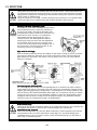
13. REPLACEMENT OF FLUORESCENT LAMP AND LAMPS
When performing the work, be sure to turn power off. Working
with power on can cause an electric shock or short circuit accident.
The Fluorescent Lamp, when it gets hot, can cause burns. Be
very careful when replacing the Fluorescent Lamp.
To perform work safely and securely, be sure to prepare a step which is in a
secure and stable condition. Not using a step or using an unstable step can
cause violent falling down accidents.
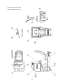
13 -1 REPLACEMENT OF FLUORESCENT LAMP
1
Take out the 2 screws to remove the FL
Cover Plate, and replace the Fluorescent
Lamp. (FRONT)
2
Take out the 3 screws to remove Billboard
Lid, and replace Fluorescent Lamp.
(REAR)
47
13 - 2 LAMP REPLACEMENT
1
Remove Wire Covers A and B
2
Disconnect the connector, take out the screw to remove the Lamp Unit, and replace the lamp.
48
14. PERIODIC INSPECTION TABLE
The items listed below require periodic check and maintenance to retain the performance of
this machine and ensure safe operation.
Be sure to check once a year to see if Power Cords are damaged, the plug is
securley inserted, dust is accumulated between the Socket Outlet and the Power
Plug, etc. Using the product with dust as is accumulated can cause a fire or
electrical shock.
Periodically once a year, request the place of contact herin stated or the Distributer, etc. where the product was purchased from, as regards to the interior
cleaning. Using the product with dust as is accumulated in the interior without
cleaning can cause a fire or short circuit accident. Note that cleaning the interior
parts can be performed on a pay-basis.
CLEANING CABINET SURFACES
If the cabinet is badly stained, use a cloth which is dipped in the chemical detergent liquid diluted with water and then
squezzed dry. Do not use thinner, benzine, alcohol or chemical dustcloth as these can damage Cabinet surfaces.
SEAT (Greasing to Seat Rail Portion)
Move the Seat to the rearmost portion and apply spray greasing to the
portion shown at the right once every 3 months by using NOK KLUBER
L60 or GREASE MATE SEGA PART No. 090-0066. After greasing, move
seat a few times forward and backward so as to allow the grease to be
applied all over uniformly. Be sure to wipe grease which attaches to the
surfaces of the PROTECT RUBBER on the seat Rail, or any excess grease.
49
15. TROUBLESHOOTING
Should trouble occur, first check connector connections.
PROBLEMS
CAUSE
COUNTERMEASURES
With Main SW
ON, no activation
Power is not supplied.
Plug in correctly
Power supply/voltage is not correct.
Make sure that power supply/voltage is
correct.
Check fuse. Remove the cause of
overload and replace fuse
AC main fuse causes the
power to be cut off due to momentary
overload.
Operation is
unsatisfactory
Volume Setting Failure
Perform Volume setting
Adjust or replace V.R.
Poor mesh of V.R. gear.
Adjust Gear mesh..
Spring failure due to secular change
of Accelerator and Brake Mecha.
Replace the Spring.
Irregular sound
emitted from
inside Rear Cabinet
Greasing to gear mesh portion is not
satisfactory, or extraneous matter
mixed in.
Apply greasing or eliminate extraneous
matter.
The color of the
image on PROJ.
screen is incorrect.
Connector connections are defective.
Check the connection for the RGB and
SYNC connectors of the PROJ. TERM.
BD and VPM BUFFER BD.
The image on PROJ.
screen has color
deviation.
Affected by the magnetic field of
installation location.
Make CONVERGENCE adjustment.
(Refer to Section 9.)
No sound is emitted.
Sound Volume adjustment is not
appropriate.
Adjust sound volume. (see Section 6).
Sound BD and speaker are
malfunctioning.
Perform sound test to find and replace
defective parts.(Refer to Section 6).
NETWORK check
will not finish.
Communication cable’s connection
failure.
Perform V.R. setting, Adjustment.
Communication play
is not possible.
Communication cable’s connection
failure.
Communication Play setting is wrong.
Check for Communication cable
disconnection
Correctly set in test mode.
No sound from
Cockpit.
In correct Cabinet Type Setting.
Correct Cabinet Type Setting.
The Fluorescent
lamp does not
light up.
The Fluorescent tube is burnt out.
Replace the Fluorescent tube
(Refer to Section 10).
Shift operation is not
is not satisfactory in
Manual transmission.
Shift SW malfunctioning.
Replace SW
50
16. GAME BOARD
In order to prevent an electrical shock, be sure to turn power off before
performing work by touching the interior parts of the product.
Be careful so as not to damage wirings. Damaged wiring can cause an
electric shock or short circuit accident.
Do not expose the Game BD, etc. without a good reason. In this product,
setting changes are made during the test mode. The Game BD need not be
operated. Use the Game BD, etc. as is with the same setting made at the
time of shipment.
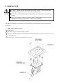
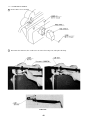
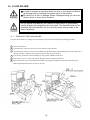
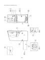
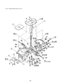
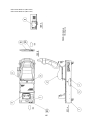
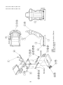
16 -1 REMOVING THE GAME BOARD
To replace the IC Board or to change dip switch settings, take out the IC board using the following procedure;
1 Turn main switch off.
2 Unlock the base, and remove the 2 truss screws from the side of the base.
3 Turn the knob to unlock. The seat can be inclined in the direction shown. When inclining the seat, be careful not to
damage seat parts. Carefully rest the backrest portion of the seat on the ground.
4 If neccessary, protect the seat from damage by using a cloth or blanket on the floor.
5 Take off the 3 screws to remov eth case lid. The game board is inside the shield case.
6 Take off a total of 4 screws from both sides with the seat being inan inclined state and remove the base lid F.
Removing base lid F allows the elec base to be seen.
51
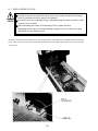
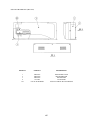
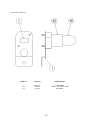
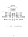
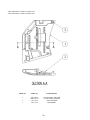
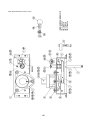
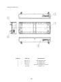
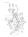
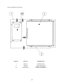
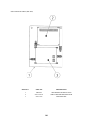
16 - 2 REPLACEMENT OF FUSE
In order to prevent an electric shock, be sure to turn power off before performing
work by touching the interior parts of the product.
Be careful so as not to damage wirings. Damaged wiring can cause an electric shock
or short circiut accident
After eliminating the cause of the blowing of fuse, replace the fuse.
Depending on the cause of the fuse blowing, using the fuse as is blown can cause
generation of heat resulting in fire.
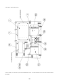
Incline the Seat and remove the Base Lid to view the Base interior. The composition of the Base interior is as shown
below. There is a fuse on each of the Connect BD. and Motor Drive BD. When replacing the fuse, be sure to use the
specified one.
52
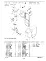
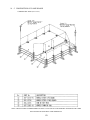
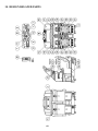
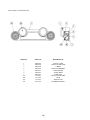
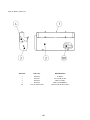
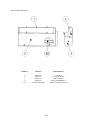
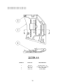
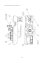
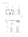
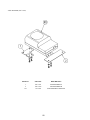
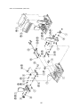
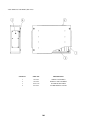
16 - 3 COMPOSITION OF GAME BOARD
GAME BD SRT TWIN (833-13373)
NOTE: THIS PICTURE IS FOR REFERENCE ONLY!! UNIT IS NOT TO BE OPENED. EXPOSING THE GAME
BD FOR ANY REASON MAY VOID WARRANTY.
53
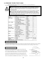
16 - 4 ERROR DISPLAY (DRIVE CONTROL BOARD)
Be Careful so as not to damage wirings. Damaged wirings can cause an electric shock
or short circuit accident.
Do not touch places other than those specified. Touching places not specified can
cause an electric shock or short circuit accident.
If an irregularity occurs inthe Drive Control Board, etc., the ERROR message is shown ont he screen and the 7-SEG
display ont he Drive Control Board. Take countermeasures in the manner corresponding to the ERROR message. Note
that even at the time of error occurence, game play is possible without Steering Wheel reaction.
Among the ERROR display as per the Table listed below, each Er 01, 02, 20, and 22 is displayed if an irregularity is
found during initialization setting movements when power is turned on and at the time Test Mode is finished.
From among error displays as per the Table shown below, Er 23, 24, and 25 indicate On-Board 7-SEG error display
when an irregularity is found during game and ADVERTISE MODE. If an irregularity is found during game, game play
can be continued without Steering Wheel reaction.
54
If ERROR display is shown on the screen, incline the Seat WITHOUT TURNING POWER OFF, and remove Back
Lid B to check the 7-SEG display ont he Drive Control Board. At this time, if the power is turned off, each of the Er 23,
24, and 25 which could have occured during operation may not be displayed.
55
17. COMMUNICATION PLAY
Before performing between-cabinets connection work, be sure to turn the Power
SW OFF and unplug the power plug from the wall socket. Failure to observe this
can cause electric shock and/or short circuit accidents.
Perform assembling as shown in this manual. Erroneous assembling can cause
electric shock accidents and malfunctioning.
By linking 4 machines, up to 4 persons can play simultaneously. Although accessory parts are to be installed for
communication play, some of the parts will remain as spares.
17 - 1 INSTALLATION PRECAUTIONS
1
Simple multiple machines are to be linked, sufficient
power corresponding to the number of machines used
need to be supplied. As standard, amperage is 15A
(AC100~110~120V area).
2 Due to the parts used for communication play, interval
between machines is 20 cm. If parts are not installed,
adjascent players will come into contact with each other
and this can cause accidents and trouble.
17 - 2 CONNECTING THE COMMUNICATION CABLES
The Communication Cable is optic-fiber made and will break if excessively bent.
Handle with care.
The Protect Tube is used to link plural machine units and the communication cables are caused to pass through the
Protect Tube. Depending on the number of machine units to be linked, connect the communication cables in the manner
descibed on page 58.
56
1 To assemble your Rally 2 Twin Game locate the Left Cabinet (side with on/off switch), Cash Box Tower, and Right
Side Cabinet. In the parts bag located in the cash box, locate the Opto Cable. this will be needed later, to connect
together the opto connections on the rear of the Cash Box Tower. The hardware needed to assemble your Rally 2
Twin game has been threaded into the proper holes. This was done to insure the bolts thread properly into the T
nuts in the Cabinet.
2 At this time remove the rear cover of the Cash Box Tower.
3 Notice the wire harness taped to both sides of the cabinets and Cash Box Tower. On the wireharness connections
Black is for the left side, yellow is for the right side viewed from the front. Locate left side cabinet (on/off switch)
and Cash Box Tower. Connect the 15, 4 and 2 position connectors together. At this time connect the Opto cable
(without white lable) to the Opto connection nearest to the left side of cabinet (viewed from the front). These Opto
connections are in the rear of the Cash Box Tower.
4 You may elect no to connect the connector at this time, but carefully push connectors in the hole so they are still
accessible from the outside of the cabinet.
5 There are 4 bolts in the NON SLOTTED HOLES, on the side of the cabinet, the 2 on top under the the ledge must
be removed. The 2 on the bottom must be loosened about 1/4 inch. Lift up the Cash Box Tower and using the 2
lower slotted holes on the bottom of the Cash Box slip them over the lower protruding bolts and slide the cash box
into place. Open the Coin Door and install the 2 upper bolts through the cash box into the cabinet. tighten all 4
bolts.
6 The Right side of the cabinet gets installed the same way as the left side.
57
58
17 - 3 SETTING FOR COMMUNICATION PLAY
During communication play, if communication is interrupted due to a certain
cause, ERROR MESSAGE will be displayed, then NETWORK check mode appears on
the screen automatically.
Cause all of the seats to enter the Test Mode and change the GAME ASSIGNMENTS of each seat for communication
play. Refer to the section on Explanation of Test and Data display for changing procedure.
1
Press the TEST button to enter the test mode and choose “GAME ASSIGNMENTS”.
2
Bring the arrow to LINK TYPE and press the TEST BUTTON and set plural numnber of machines sequentially
to CAR 1, CAR2, CAR3 and CAR4 as applicable starting fromthe extreme left facing the monitor’s front side. I f
the same number is set for 2 or more cabinets, or if the sequential order is incorrect, the game display, etc. will be
confused (different fromthe actual status). Therefore, be careful of this point.
3
In case of communication play, only the settings of GAME DIFFICULTY and GAME MODE need to be
performed by the MASTER seat. All other seats (SLAVE) are subject to the setting made by the MASTER CAR1
seat. The above setting change made by any SLAVE seat is not effective and will not be reflected on the game.
GAME ASSIGNMENTS
ADVERTISE SOUND
ON
DIFFICULTY
NORMAL
GAME MODE
NORMAL
DEFAULT VIEW
DRIVER
SPEED
KM/H
DISPLY URL
OFF
CABINET TYPE
TWIN
LINK TYPE
MASTER (CAR1)
>EXIT
SELECT WITH SERVICE BUTTON
AND PRESS TEST BUTTON
59
18. DESIGN RELATED PARTS
60
DESIGN RELATED PARTS
61
19. PARTS LIST
TOP ASSYSEGA RLLY 2 TWIN
62
TOP ASSY SEGA RALLY2 TWIN
ITEM NO.
PART NO.
DESCRIPTION
1
2
3
4
5
15
16
17
19
20
21
22
23
24
25
101
SRT-10001
SRT-11001
SRT-0200
SRT-0300
422-0663-01
421-8543
421-8544
421-7308~
RAL-0006
SPG-0006
DYN-0006X
INY-0004
DYN-0008
DYN-0009
DYN-0011
600-6275-0500
ASSY COCKPIT 1P
ASSY COCKPIT 2P
ASSY BILLBOARD
ASSY COIN CHUTE TOWER
SUB INSTR SH SRT TWIN ENG
STICKER CABINET L
STICKER CABINET R
DENOMINATION SHEET 1GAME~
BLIND CAP
AC COVER A
AC COVER B
BACK LID INY
BACK LID B
HOLE LID
DENOMI PLATE W/O ORIGINAL
ASSY FIBER CABLE 5 0500CM
63
ASSY BILLBOARD (SRT-0200)
ITEM NO.
PART NO.
DESCRIPTION
1
2
3
4
5
6
8
9
10
SRT-0201-01
SRT-0202
SRT-0206
SRT-0215
SRT-0218
SRT-0219
SRT-0221
SRT-0222
SRT-0227
BILLBOARD FRAME EXP
ASSY BILLBOARD BOX
ASSY LIGHT COVER
ASSY FL BOX L
WIRE COVER A
WIRE COVER B
WIRE COVER L
WIRE COVER R
ASSY FL BOX R
64
ASSY BILLBOARD BOX (SRT-0202)
ITEM NO.
PART NO.
DESCRIPTION
1
2
3
4
101
SRT-0203
SRT-0204
SRT-0205
253-5457
LOCAL PURCHASE
BILLBOARD CASE
BILLBOARD LID
BILLBOARD
FL HOLDER
ASSY FL 20W EX W/CONN HIGH S
65
ASSY LIGHT COVER (SRT-0206)
ITEM NO.
PART NO.
DESCRIPTION
1
2
3
4
5
6
7
101
102
103
104
SRT-0207
SRT-0208
SRT-0209
SRT-0210
SRT-0211
SRT-0212
SRT-0213
253-5461
275-0134
105-5325
280-5328
LIGHT COVER
LIGHT COVER BASE
L BRKT
LIGHT COVER BRKT
LENS HOLDER
LIGHT BRKT
LAMP UNIT
LIGHT COVER CIBIE
LENS
REFLECTOR
RUBBER PACKING
66
LAMP UNIT (SRT-0213)
ITEM NO.
PART NO.
DESCRIPTION
1
101
102
SRT-0214
390-6567
214-0110
LAMP BRKT
LAMP 110V 15W YELLOW
BULB SKT
67
ASSY FL BOX L (SRT-0215)
ITEM NO.
PART NO.
DESCRIPTION
1
2
3
4
101
SRT-0216
SRT-0217
SRT-0223
SRT-0225
LOCAL PURCHASE
FL BOX L
FL COVER PLATE
SIDE COVER L
SIDE COVER BRKT L
ASSY FL 6W SD W/CONN S
68
ASSY FL BOX R (SRT-0227)
ITEM NO.
PART NO.
DESCRIPTION
1
2
3
4
101
SRT-0220
SRT-0217
SRT-0224
SRT-0226
LOCAL PURCHASE
FL BOX R
FL COVER PLATE
SIDE COVER R
SIDE COVER BRKT R
ASSY FL 6W SD W/CONN S
69
ASSY COINCHUTE TOWER (SRT-0300)
70
ASSY COINCHUTE TOWER (SRT-0300)
ITEM NO.
PART NO.
DESCRIPTION
1
2
3
4
5
10
11
12
13
101
102
103
104
105
SRT-0350
SPG-0301
DYN-0302Y
DP-1167
BOX-CASH
DYN-0305
105-5202
SPG-0302
SPG-0303
220-5237-92
220-5412
220-5412-01
220-5574
220-5575
SW UNIT
COIN CHUTE TOWER
COIN METER BRKT
TNG LKG
CASH BOX
TOWER BRKT
HOLE COVER
WIRE BOX
WIRE BOX LID
ASSY C.C. 2DR
MAG CNTR W/CONN
MAG CNTR W/CONN BLACK
CAM LOCK W/KEYS
CAM LOCK MASTER W/O KEY
71
SW UNIT (SRT-0350)
ITEM NO.
PART NO.
DESCRIPTION
1
101
102
103
UCQ-1035
509-5028
220-5296
601-0042
SWITCH BRKT
SW PB 1M
VOL CONT 5KOHMx2 +/-10% RV24G
KNOB 22MM
72
ASSY COCKPIT 1P (SRT-10001)
ASSY COCKPIT 2P (SRT-11001)
73
ASSY COCKPIT 1P (SRT-10001)
ASSY COCKPIT 2P (SRT-11001)
ITEM NO.
PART NO.
DESCRIPTION
1
SRT-20001
SRT-21001
SRT-1030
SRT-1040
SRT-1035
SRT-1045
SRT-12001-01
SRT-1001
SRT-1002
INY-1016
SPG-1008
TTR-1067X
SPG-1005
DYN-1025
INY-1015
SRT-4550
200-5242-24-04
200-5243-24
280-5112
280-5113
280-5114
280-5185-6
601-6231-C100
ASSY MAIN BASE 1P
ASSY MAIN BASE 2P
ASSY MONITOR COVER L 1P
ASSY MONITOR COVER L 2P
ASSY MONITOR COVER R 1P
ASSY MONITOR COVER R 2P
ASSY CONTROL PANEL TWIN EXP
MONITOR STAND
WIRE COVER BOX
MONITOR SUPPORT
ROOF LID
MONITOR MASK
MASK HOLDER
RUBBER CUSHION
CRT ADJUST PANEL
ASSY DRIVE BD TWIN
ASSY CLR DSPL 29 TYPE 100V
ASSY CLR DSPL 29 TYPE 24K 100V
BUSH FOR TV
COLLAR FOR TV
SPACER 6.4-25x2
SPACER TUBE L=6
EDGING NEW TYPE
2
3
4
5
6
7
8
9
10
11
12
14
101
105
106
107
108
109
74
ASSY MONITOR COVER L 1P (SRT-1030)
ASSY MONITOR COVER L 2P (SRT-1040)
ITEM NO.
PART NO.
DESCRIPTION
1
SRT-1031
SRT-1031-A
SPG-1100
DYN-1032
COVER PANEL L 1P
COVER PANEL L BLANK
ASSY SPEAKER
MASK BRKT
2
3
75
ASSY MONITOR COVER R 1P (SRT-1035)
ASSY MONITOR COVER R 2P (SRT-1045)
ITEM NO.
PART NO.
DESCRIPTION
1
SRT-1046-A
SRT-1046-01
SPG-1100
DYN-1032
COVER PANEL R BLANK
COVER PANEL R 2P EXP
ASSY SPEAKER
MASK BRKT
2
3
76
ASSY SPEAKER (SPG-1100)
ITEM NO.
PART NO.
DESCRIPTION
1
101
INY-1701
130-5152
SPEAKER BRKT
SPKR BOX MINI DOME 12W
77
ASSY CONTROL PANEL TWIN EXP (SRT-12001-01)
78
ASSY CONTROL PANEL TWIN EXP (SRT-12001-01)
ITEM NO.
PART NO.
DESCRIPTION
1
2
3
4
5
6
7
8
9
10
11
12
13
14
101
SPG-2001
DYN-1209X
SPG-2002
SRT-1201-01
SPG-1205
DYN-1222
DYN-1223X
SPG-1203
SPG-1204
SPG-2500
SPG-2150
SRT-1290
SPG-2039
601-8543
260-0011-02
STEERING WHEEL
HANDLE COLLAR
STEERING EMBLEM
CONTROL PANEL COVER ENG
CONTROL PANEL BRKT
SHIFT COVER A
SHIFT COVER B
FAN BRKT
SPL BLT M8
ASSY HANDLE MECHA
ASSY 4 SPEED SHIFTER
ASSY VIRTUAL BUTTON TWIN
SPACER RING
FAN GUARD
AXIAL FLOW FAN AC 100V 50-60HZ
79
ASSY HANDLE MECHA (SPG-2500)
80
ASSY HANDLE MECHA (SPG-2500)
ITEM NO.
PART NO.
DESCRIPTION
1
2
3
4
5
6
7
8
9
10
11
12
13
14
15
101
102
103
104
105
106
107
108
SPG-2501
SPG-2502
SPG-2503
SPG-2504
SPG-2505
SPG-2506
SPG-2507
SPG-2108
SPG-2109
SPG-2453
ASK-3502
ASK-3503
DYN-1270
SLC-1130
SPG 2454
350-5448-01
100-5112
601-8966
601-6172
601-6959
601-9173
220-5484
310-5029-F20
HANDLE BASE
BASE LID
HANDLE SHAFT
PULLEY 20 S5M
PULLEY 60 S5M
MOTOR BRKT
VR BRKT
STOPPER BOLT
STOPPER RUBBER
KEY 4X4X40
MOTOR SPACER
MOTOR COLLAR
STOPPER KEY
ADJUST RING
MOTOR SHAFT COLLAR
SERVO MOTOR 500W NEW
BEARING 17
GEAR HOLDER
GEAR 48
GEAR 64
TIMING BELT
VOL CONT B-5K OHM
SUMITUBE F F 20MM
81
ASSY 4 SPEED SHIFTER (SPG-2150)
82
ASSY 4 SPEED SHIFTER (SPG-2150)
ITEM NO.
PART NO.
DESCRIPTION
1
2
3
4
5
6
7
8
9
10
11
12
13
14
15
101
102
103
104
106
107
201
202
203
204
205
206
207
208
209
210
SPG-2151
SPG-2152
SPG-2153
SPG-2154
SPG-2155
SPG-2156
SPG-2157
SPG-2158
SPG-2159
SPG-2160
SPG-2161
SPG-2162
SPG-2163
SPG-2164
SPG-2165
100-5252
100-5193
100-5170
509-5636
280-5306
280-5307
000-F00406
000-O00410-W
000-P00420-W
000-P00508-W
050-H00600
060-S00600
065-S010S0-Z
FAS-00033
FAS-650008
FAS-450006
SHIFT KNOB
STOPPER RUBBER
FRONT BASE
SLIDE COVER
SLIDE PLATE
REAR BASE
RUBBER BLOCK 45
RUBBER BLOCK 65
INSULATOR SHEET
SHAFT CASE
SHAFT BOLT
CENTERING BLOCK
RUBBER CASE
ROLLER BOLT
ROLLER SUPPORT
BEARING ROLLER 25
GROMMET 11
BEARING 8
SW MICRO TYPE SS-5GL2T
SPACER FAI 6X30
SPACER FAI 8X55
M SCR FH M4X6
M SCR PH W/FS M4X10
M SCR PH W/FS M4X20
M SCR PH W/FS M5X8
HEX NUT M6
SPR WSHR M6
STP RING BLK OZ S10
M SCR PH W/FS M2.3X12
WAVE WSHR 12.7-18.1X2.5
SPR PIN WAVE STN 5X45
83
ASSY VIRTUAL BUTTON TWIN (SRT-1290)
ITEM NO.
PART NO.
DESCRIPTION
1
2
101
102
103
RAL-1291
171-6478B
212-5205-12
509-5205-Y
509-5561-S
VR BUTTON BRKT
PC BD LIGHTING SWX5
CONN JST M 12P RTA
PB SW W/L 6V 1L Y
PB SW W/L 6V 5L S
84
ASSY MAIN BASE 1P (SRT-20001)
ASSY MAIN BASE 2P (SRT-21001)
85
ASSY MAIN BASE 1P (SRT-20001)
ASSY MAIN BASE 2P (SRT-21001)
ITEM NO.
PART NO.
DESCRIPTION
1
2
SRT-1500
SRT-1600
SRT-1700
SPG-2200
SRT-4400
SRT-4500
SRT1-0400-01
SPG-1502
RAL-2007
RAL-2008
SPG-1503
260-0011
600-6275-0150
ASSY BASE BOX
ASSY SEAT TWIN 1P
ASSY SEAT TWIN 2P
ASSY ACCEL&BRAKE
ASSY MAIN BD BASE
ASSY ELEC BASE
AC UNIT MAIN EXP (1P)
PEDAL BASE
RUBBER HOLDER R TWIN
RUBBER HOLDER L TWIN
FAN BRKT
AXIAL FLOW FAN AC100V 50-60 HZ
ASSY FIBER CABLE 5 0150CM
3
4
5
6
7
8
9
10
101
102
86
AC UNIT MAIN (SRT-0400)
TEM NO.
PART NO.
DESCRIPTION
1
101
102
103
105
107
108
SPG-0401X
600-5843-25
280-5134-6N34
LOCAL PURCHASE
509-5453-91-V-B
280-0417
211-5479
AC BRKT
CA & PLUG ASSY 15A W/F-L=2.5M
BUSHING STRAIN RELIEF 6N34
FUSE 7A Slo
SW ROCKER J8 V-B
TERMINAL BINDING POST BLACK
CONN OPT JOINT
87
ASSY BASE BOX (SRT1-1500)
ITEM NO.
PART NO.
DESCRIPTION
1
2
3
4
5
6
7
8
101
DYN1-2002
DYN1-2003
DYN1-2004
DYN1-2005
DYN1-2006
DYN1-2010
DYN1-2007
DYN1-2008
999-0168
MAIN BASE
BASE LID F
LOCK TNG
FLOOR MAT
HINGE 480
BASE LID R
LID EDGE L
LID EDGE R
CAM LOCK MASTER W/O KEY
88
MAIN BASE (SRT0-1501)
ITEM NO.
PART NO.
DESCRIPTION
1
2
3
4
5
SRT-1501-A
SRT-1501-B
SRT-1501-C
999-0167
999-0169
MIAN BASE BLANK
STICKER BASE L
STICKER BASE R
LEG ADJUSTER BOLT 1/2X13X3
CASTER 2 1/2"
89
ASSY SEAT TWIN 1P (SRT-1600)
ASSY SEAT TWIN 2P (SRT-1700)
90
ASSY SEAT TWIN 1P (SRT-1600)
ASSY SEAT TWIN 2P (SRT-1700)
ITEM NO.
PART NO.
DESCRIPTION
1
2
3
4
5
6
STC-1650
SPG-2401
SPG-2402
SRT-1604
STC-1604
SRT-1601
SRT-1701
STC-1606
STC-1607
STC-1608
STC-1609
STC-1610
STC-1611
STC-1612
STC-1613
INY-1302-B
SPG-2404
SRT-2200
601-9059
601-9060
130-5159
601-6563-188
601-6563-100
280-5297
000-P00410-W
030-000816-S
050-H00800
060-S00800
000-T00616-0B
030-000820-SB
060-F00800-0B
ASSY WOOFER
UPPER SEAT
LOWER SEAT
SEAT BASE
SEAT FRAME
SEAT REAR COVER 1P
SEAT REAR COVER 2P
SEAT MOUNT TRAY
SP MOUNT BRKT
SPEAKER NET L
SPEAKER NET R
SAFETY GUARD
CABLE BEAR BRKT
PROTECT RUBBER
SAFETY GUARD F
MASK CUSHION SIDE
SEAT FRAME BRKT
ASSY HAND BRAKE
SEAT RAIL L
SEAT RAIL R
GULL BOX SPEAKER 80OHM 5W
BUSH 2.4T
BUSH 2.4T
SCRIVET 8 1K31
M SCR PH W/FS M4X10
HEX BLT W/S M8X16
HEX NUT M8
SPR WSHR M8
M SCR TH BLK M6X16
HEX BLT W/S BLK M8X20
FLT WSHR BLK M8
7
8
9
10
11
12
13
14
15
16
17
101
102
103
105
106
107
201
203
205
206
210
212
213
91
ASSY WOOFER (STC-1650)
ITEM NO.
PART NO.
DESCRIPTION
1
2
101
STC-1651
STC-1652
130-5160
WOOFER BRKT F
WOOFER BRKT R
SUB WOOFER 4 OHM 30W
92
ASSY HAND BRAKE (SRT-2200)
93
ASSY HAND BRAKE (SRT-2200)
ITEM NO.
PART NO.
DESCRIPTION
1
2
3
4
5
6
7
8
9
10
11
12
13
14
15
16
17
18
19
101
102
103
104
201
202
203
204
205
206
207
208
209
SRT-2201
SRT-2202
SRT-2203
SRT-2204
SRT-2205
SRT-2206
SRT-2207
SRT-2208
SRT-2209
SRT-2210
SRT-2211
SRT-2212
SRT-2213
SRT-2214
SRT-2215
SRT-2216
SRT-2217
SRT-2218
SRT-2219
100-5319
509-5636
601-5564
280-5029-F15
FAS-450012
065-E00800
065-E01000
020-000508-OZ
060-S00500-OB
000-P00516-S
FAS-000049
FAS-000050
FAS-000051
PIPE SHAFT
PIPE HOLDER
HOLDER SHAFT
STOPPER SHAFT N
STOPPER SHAFT
SPRING
SENSOR STAY
PIPE GUIDE
GUIDE BRKT
FRONT COVER
SIDE COVER A
SIDE COVER B
UNDER COVER
MECHA BRKT
STAY
STOPPER RUBBER
STOPPER RUBBER N
DAMPER STAY
INSULATOR SHEET
BEARING 10
SW MICRO TYPE SS-5GL2T
STOPPER
CORD CLAMP SR10
SPR PIN BLK OZ 5X30
E RING 8MM
E RING 10MM
HEX SKT H CAP SCR BLK M5X8
SPR WSHR BLK M5
M SCR PH W/S M5X16
M SCR TH BLK M4X5
M SCR PH W/FS M2.3X10
M SCR TH BLK M5X10
94
ASSY ACCEL&BRAKE (SPG-2200)
95
ASSY ACCEL&BRAKE (SPG-2200)
ITEM NO.
PART NO.
DESCRIPTION
1
2
3
4
5
6
7
8
9
10
11
12
13
14
15
16
17
19
20
21
101
102
104
105
106
201
202
203
204
205
206
207
208
209
210
SPG-2201
SPG-2202
SPG-2203
SPG-2204
SPG-2205
SPG-2206
SPG-2207
SPG-2208
SPG-2209
SPG-2210
SPG-2211
SPG-2212
SPG-2213
SPG-2214
SPG-2215
SPG-2216
SPG-2217
SPG-2219
SPG-2220
SPG-2221
100-5263
220-5484
601-7944
310-5029-F15
280-0419
028-A00304-P
020-000520-0Z
000-P00420
000-P00508-W
000-T00408-0C
FAS-450005
000-P00405
FAS-000001
050-H00500
060-F00400
BASE
ACCEL PEDAL
BRAKE PEDAL
ACCEL SPRING
BRAKE SPRING
SHAFT
ACCEL GEAR
BRAKE GEAR
NUETRAL STOPPER
VR PLATE ACCEL
VR PLATE BRAKE
AMPL GEAR
GEAR SHAFT
STOPPER
RUBBER CUSHION
COVER
VR COVER
GEAR STAY
WSHR
NUETRAL STOPPER
BEARING 12
VOL CONT B-5K OHM
GEAR 15
SUMI TUBE F F 15MM
HARNESS LUG
SET SCR HEX SKT CUP P M3X4
HEX SKT H CAP SCR BLK M5X20
M SCR PH M4X20
M SCR PH W/FS M5X8
M SCR TH CRM M4X20
SPR PIN BLK OZ 6X10
M SCR PH M4X5
M SCR TH CRM M3X6
HEX NUT M5
FLT WSHR M4
96
ASSY MAIN BD BASE (SRT-4400)
ITEM NO.
PART NO.
DESCRIPTION
1
2
3
101
SRT-4401
SRT-4600
105-5241
400-5330-02-91
WOODEN BASE
ASSY SHIELD CASE
SHIELD CASE BRKT
SW REGU FOR MODEL 3
97
ASSY ELEC BASE (SRT-4500)
NOTE: ITEM #103 MAY BE INSTALLED PERPENDICULAR TO THIS BOARD TO ALLOW ROOM FOR DRIVE
BOARDS.
98
ASSY ELEC BASE (SRT-4500)
ITEM NO.
PART NO.
DESCRIPTION
1
2
3
101
102
103
105
106
107
108
SRT-4501
SRT-4700
105-5317
560-5359
838-10801
838-11650-38
838-11651-91
839-0542
LOCAL PURCHASE
839-0542-02
WOODEN BASE ELEC
ASSY SHIELD CASE MPEG
SHIEDL CASE BRKT MPEG
PWR XFMR 100V 6.5A 12.5V 6Ax2
CONN BD B
EQ. PWR AMP SRT TWIN F
LOWPASS AMP
AUDIO MIX BD
FUSE 7A SLO
AUDO MIX BD R
99
ASSY SHIELD CASE MPEG (SRT-4700)
ITEM NO.
PART NO.
DESCRIPTION
1
2
3
4
105-5315
105-5316
837-13376
839-1021
SHIELD CASE MPEG
SHIELD CASE LID MPEG
SOUND BD SRT TWIN
FLT BD DIGITAL SOUND
100
ASSY DRIVE BD TWIN (SRT-4550)
ITEM NO.
PART NO.
DESCRIPTION
1
2
3
SRT-4551
838-12912-01
838-13366
WOODEN BASE DRIVE TWIN
SERVO MOTOR DRIVE BD NEW
DRIVE BD SRT
101
Come see Sega GameWorks Service Department’s Homepage