1
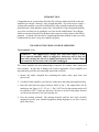
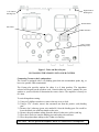
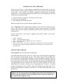
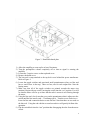
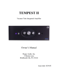
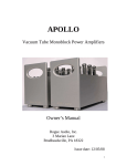
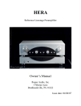
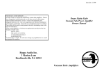
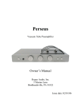
TABLE OF CONTENTS
1) Introduction
2
2) Unpacking the Cronus integrated amplifier
2
3) Installing the Cronus into your system
3
4) Operation of the Cronus
5
5) Setting the tube bias
5
6) Troubleshooting
7
7) Registration card
7
8) Fuse values
8
9) Specifications
8
10) Warranty
9
1
INTRODUCTION
Congratulations on your purchase decision! We at Rogue Audio truly believe that our
amplifiers provide the “smartest” value in high-end audio. If you have never owned a
vacuum tube amplifier you will be thrilled by the silky-smooth sound and incredible
detail that only a tube amplifier can provide. And with the Cronus integrated amplifier,
you can be sure that you are getting the very best in tube amplification. We at Rogue
Audio are extremely proud of our products and want you to enjoy them to their fullest
potential. So please, take the time to read through this short manual so that you can be
confident that you have set up your amplifier properly.
UNPACKING THE CRONUS POWER AMPLIFIER
Tools required: none
WARNING - This amplifier uses voltages that could cause injury or death.
Never open the amplifier while it is plugged in, and always wait at least one
hour after turning the unit off to unplug and open the unit. Lethal voltages
can remain in the electronics after the unit is unplugged.
The Cronus amplifier has been painstakingly inspected for cosmetic flaws during and
after assembly. In order not to damage the cosmetic appearance of your amplifier it is
important that you follow the unpacking instructions carefully.
1. Remove the small corrugated box containing the remote, tubes, spare fuses, and
power cord.
2. Carefully lift the amplifier out of the box, and remove the foam pads and plastic bag.
3. Insert the tubes into the proper locations. Refer to Fig. 1 The output tubes will be
marked per the figure. (ie V1,V2, etc. ). The 12AU7 used in the preamp section will
be marked as 12AU7 Center per the figure. Be sure to use this in the proper location
as it has been selected for low noise preamp use.
4. Save the packing materials. The packing materials and box have been carefully
designed to protect your valuable equipment during shipping so you don’t want to
throw them away.
2
Right Channel
Binding Post
Left Channel
Binding Post
Potentiometers
Bias Meter
Bias Switches
12AU7 Center
(Preamp Tube)
Figure 1. Tube and Deck Layout
INSTALLING THE CRONUS INTO YOUR SYSTEM
Connecting Cronus to the Loudspeakers:
The Cronus is equipped with 5 way binding posts that can accommodate spade, lug, or
bare wire speaker cable terminations.
The Cronus also provides options for either 4 or 8 ohm speakers. The impedance
selected will depend on the speakers used. Consult either the owner’s manual for your
speaker or your local dealer to determine the correct choice. The amplifier is factory set
to 8 ohm.
To switch impedance setting:
1) Using a #2 phillips screwdriver, remove the top cover or deck.
2) Using a 5/16” wrench, remove the outermost nut from the positive (red) binding
post.
3) Remove the 8 ohm tap (green wire marked 8) from the binding post. Be careful to
leave the black wire with heat shrink on the post.
4) Remove the polyurethane tubing from the unused 4 ohm wire (yellow) and lug.
5) Place the 4 ohm wire onto the binding post and replace the outer nut.
6) Place the polyurethane tubing on the 8 ohm wire and lug.
CAUTION – Do not operate the amplifier unless it is connected to a loudspeaker.
3
Connecting Cronus to source components:
The input connections to the Cronus are made via RCA jacks on the rear of the
amplifier. See figure 2. Be sure to use high quality interconnect cables – they do make a
difference
Main Fuse
Right Channel
Binding Post
Left Channel
Binding Post
RCA
Inputs
Variable and
Fixed Outputs
Figure 1. Rear panel layout
Connecting Cronus to a turntable:
The phono section provided in the Cronus is suitable for a wide variety of cartridges.
Best results will be obtained with moving magnet (mm) and high output moving coil
(mc) cartridges. The cartridge loading is preset at 47K ohms with 150pF of capacitance.
Connecting Cronus to headphones :
The headphone jack is located on the front faceplate of the preamplifier, as shown in
figure1. The Cronus headphone jack provides for a ¼” or 6mm headphone connector. If
you have headphones with a different size connector, you can use a suitable adapter. It is
normal for a small amount of sound to come out of the loudspeakers when the
headphones are plugged in.
Connecting Cronus to the power outlet:
Connect the IEC send of the detachable power cord provided to the amplifier, and plug
the opposite end into corresponding outlet. It is recommended that both Cronus’ and all
sources (CD, tuner, etc.) are plugged into the same wall outlet if possible (perhaps using
a power outlet strip). This is to avoid creating a ground loop.
Amplifier Location:
The Cronus is an open tube design and depends on natural convection flow patterns for
proper cooling. To ensure proper cooling, the unit should be located in a position so that
the airflow is not impeded. In addition, the unit should not be placed in an enclosed
shelf, and should have a minimum of 6 inches of free space above it.
4
OPERATION OF THE AMPLIFIER
Powering up the System - After all proper connections have been made, you are now
ready to turn the Cronus integrated amplifier on. The power on/off switch is on the front
of the amp. Some sources can generate dangerous transients that can damage
loudspeakers. To avoid letting dangerous transients reach your loudspeakers turn your
system on in the following order:
1) Turn on all sources (CD, tuner, etc.) that you will be using.
2) Power up Cronus amplifier
3) Select listening source and play music
When powering down your system turn the amplifier off first.
Note – Important! After turning off the amplifier, wait at least one minute to turn it
back on. Do not turn it on then off and then on again in quick succession. Doing this
will not allow the power supply to discharge between on/off cycling and may result in
transient noises.
Switches and Controls- The Cronus is equipped with volume, balance, source, and a
remote volume.
•
•
•
•
•
Volume – adjust gain
Balance - left and right channel balance
Source – selects source material (PHONO, CD, AUX 1, and AUX 2)
Power – on/off operation
Remote Volume Control – The Cronus is equipped with an analog remote volume control feature.
The volume may be adjusted manually using the knob on the front panel, or by using the remote
control provided.
SETTING THE TUBE BIAS
Tools required: bias tool (provided with amplifier)
The output tubes (the big ones) need to be “biased’ with a grid voltage that controls the
flow of electrical current through the tube. Tube biasing on the Cronus amplifier has
been designed to be both simple and effective. On some amplifiers biasing is done for
two or more tubes simultaneously. With this method, the total current flowing through
the group of tubes may be correct, but the current flow through any individual tube may
vary significantly from the optimal value. With the Cronus amplifier the bias is set
individually for each tube so that the correct operating point is assured. An added
benefit to this approach is that, should a tube fail prematurely, the single tube can be
replaced without having to purchase a matched set. Use the following procedure to set
the tube bias:
WARNING – There are dangerous and potentially lethal voltages inside this
amplifier. Do not touch any part of the amplifier other than as described below. If
you are uncertain about any of these instructions, please contact your dealer and
have them bias the amplifier for you.
5
Figure 3. Removable hatch plate
1) Allow the amplifier to warm up for at least 30 minutes.
2) Turn the preamplifier volume completely off so that no signal is entering the
amplifier
3) Loosen the 2 captive screws on the top hatch cover.
4) Remove the hatch cover.
5) The bias tool is snap attached to the top deck cover behind the power transformer.
Refer to Figure 1.
6) Locate the toggle switches and associated small potentiometers (they are blue and
have a small screw in the top). There are four, one for each output tube. Note the
biasing meter.
7) Make sure that all of the toggle switches are pointed towards the meter (run
position). Begin with any switch, moving the switch into the “set” position. You will
see that the meter will rise up to show that the tube’s current is now flowing through
the meter.
8) Using the bias tool, slowly turn the screw on the potentiometer that is adjacent to the
switch until the bias meter reads ~ 35 miliamps (mA). Turn the screw clockwise to
lower the bias and counterclockwise to raise the bias. Note that there are two ends on
the bias tool. Using the end with the recessed screwdriver will greatly facilitate this
operation.
9) Flip the switch back into the “run” position thus disengaging the tube from the meter
circuit.
6
10) Repeat the above steps for each of the tubes in both channels.
As it is a quick operation, the tube bias should be checked on a regular basis. Note that
the bias will change slightly on a day to day basis as the wall voltage fluctuates.
Constant biasing will wear out the bias potentiometers prematurely so do not adjust the
bias unless it is more than 4-5 mA from the correct setting.
TROUBLESHOOTING
Speaker Hum – If hum can be heard from more than a few inches from the loudspeaker,
there is probably a ground loop. Be sure to have the amp and all sources plugged into the
same outlet if possible. If this fails to cure the hum, call customer service at Rogue
Audio for further advice.
Tube will not bias – If the meter provides a reading but the tube will not bias, the tube is
probably bad. If no meter reading can be attained, check the fuse (1/4 Amp slow blow).
If the fuse is bad, replace the fuse and then set the bias. If the bias will not maintain
itself and the fuse blows again, the tube should be replaced.
Bias Meter reading is too high – Check that you do not have two of the bias switches
turned on.
Output sounds distorted - Check the bias on the output tubes to ensure that the tubes are
operating properly.
OWNER AND WARRANTY REGISTRATION FORM
Included with this manual is an Owner and Warranty Registration Form. Please take a
minute to fill out this card and return it to Rogue Audio. This card must be returned
within 30 days of purchase to validate the warranty.
7
FUSE VALUES
Main fuse located on rear panel (1) – 5 Amp slow blow
Tube Fuses (4) – 1/4 Amp slow blow
Power Supply Fuse on PCB (1) – ¾ Amp slow blow
SPECIFICATIONS
output power
55 WPC
frequency response
5Hz – 50 kHz ± 1dB
THD
< 0.1% typ, < 1% at rated power
input sensitivity
1.0 V RMS
dimensions
14 ½” W x 19” D x 7” H
weight
50 pounds (25 Kg)
shipping weight
55 lbs (27 Kg)
power requirements
115/230V - 50/60Hz
8
LIMITED WARRANTY
Warranty Period
This product has been manufactured under the highest standards of quality and workmanship. Rogue Audio Inc.
(hereinafter “Rogue Audio”) warrants this product against defects in material or workmanship as follows:
With the exception of vacuum tubes, Rogue Audio warrants to the original purchaser of this product all parts of this
product against defects in material and workmanship for a period of three years from the date of retail purchase.
Rogue Audio warrants the vacuum tubes for a period of six months from the date of retail purchase. Any defective
parts will be replaced free of charge, excluding shipping and handling.
Proof of purchase in the form of a bill of sale or recited invoice which indicates that the product is within the
warranty period must be presented to obtain warranty service. Rogue Audio suggests that the purchaser retain the
dealer’s bill of sale as evidence of the date of retail purchase.
What’s Not Covered
This warranty does not cover cosmetic damage or any damage that results from product misuse, product abuse,
installation error, connection to an improper voltage supply, accident, improper maintenance, alterations,
modifications not authorized in writing by Rogue Audio, lightening, power surges, or acts of God. Use of any other
than Rogue Audio factory parts may void this warranty.
This warranty does not cover the cost of parts and labor which would be otherwise provided without charge under
this warranty, obtained from any source other than Rogue Audio.
This warranty applies only to consumer use of this product and does not cover any product that is used in any trade
or business, or in an industrial or commercial application.
This warranty applies only to the original purchaser of this product when purchased from an Authorized
Rogue Audio dealer.
This warranty is valid only in the United States.
YOUR RIGHTS
ROGUE AUDIO LIMITS ITS OBLIGATIONS UNDER ANY IMPLIED WARRANTIES UNDER STATE LAWS
TO A PERIOD NOT TO EXCEED THE WARRANTY PERIOD. SOME STATES DO NOT ALLOW
LIMITATIONS ON HOW LONG AN IMPLIED WARRANTY LASTS, AND SOME STATES DO NOT ALLOW
THE EXCLUSION OR LIMITATION OF INCIDENTAL OR CONSEQUENTIAL DAMAGES, SO THE ABOVE
LIMITATIONS OR EXCLUSIONS MAY NOT APPLY TO YOU. THIS WARRANTY GIVES YOU
SPECIFIC LEGAL RIGHTS, AND YOU MAY HAVE OTHER RIGHTS WHICH MAY VARY FROM
STATE TO STATE.
To Obtain Service
To obtain service, you must contact Rogue Audio and obtain a return authorization number. The product must be
delivered to Rogue Audio in its original packaging prepaid at the following address:
Rogue Audio Inc.
3 Marian Lane
Brodheadsville, PA 18322
9