1
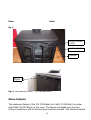
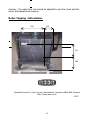
Esse
700 27B MODEL
Roomheater with boiler
WOOD BURNING ONLY MODEL
Esse Stoves & Cookers
Long Ing. Barnoldswick, Lancashire BB18 6BN. United Kingdom.
Tel: + 44 (0) 1282 813235 F: + 44 (0) 1282 816876
[email protected] www.esse.com
1
INSTALLATION & OPERATING INSTRUCTIONS
FOR THE ESSE 700 27B MODEL
U.K. & Ireland
READ THESE INSTRUCTIONS AND SAVE FOR REFERENCE
Contents
Safety Notes
Page 3
Page 4
INSTALLATION INSTRUCTIONS
Chimney and Flue
Page 4
Flue and Draught Measurement
Flue Diagnosis
Flue Stabiliser
Page 5
Page 6
Page 7
Installing the stove
Page 7
Positioning
page 7
Hearth
Page 7
Flue connection
Page 8
Important installation notes
Page 8
Positioning internal components
Page 8,9,10
Stove outputs
Page 11
The domestic and central heating system
Page 11
Final Checks
Page 12
Boiler Tapping
Page 12
………………………………………………………………………………………………
OPERATING INSTRUCTIONS
Page 14
Wood
• Lighting and controlling the fire
• Correct running temperatures for wood burning
• Extended burning
• Types of wood for fuel
Stove Guarantee
2
Page
Page
Page
Page
Page
Page
15
15
17
17
17
19
SAFETY NOTES
• Properly installed, operated and maintained, this appliance will not emit
fumes into the dwelling. However occasional fumes from de-ashing and refuelling may occur. Persistent fume emission is potentially dangerous and must
not be tolerated. If fume emission does persist, open doors and windows to
ventilate the room. Let the fire burn out or eject and safely dispose of fuel from
the appliance. Once the fire is cold, check the flue and chimney for blockages and
clean if required. Do not attempt to relight the fire until the cause of the fume
emission has been identified and corrected. Seek expert advice if necessary.
• Do not fit an extractor fan in the same room as the appliance.
• An adequate air supply for combustion and ventilation is essential. Air
openings provided for this purpose must not be restricted. This appliance requires
an air supply of 100 square cm.(16 Square Inches) in order to provide an
adequate amount of air for successful combustion.
• It is important that flue ways are cleaned frequently and the chimney
swept regularly. Also the stove must be maintained in good mechanical order.
Regular sweeping will mean at least once per year.
• If the chimney was previously used for an open fire, it is possible that the
higher flue gas temperatures generated by the stove may loosen deposits that
were firmly adhering to the inner surface of the chimney and cause blockage of
the fluepipe. We recommend that in such a situation a second sweeping of the
chimney should be carried out within one month of regular use of the stove after
installation. Also, lock or remove any existing dampers in the flueway.
• Should it be likely that children, aged or infirm people approach the fire,
then a fireguard should be fitted.
• Avoid the use of aerosol sprays in the vicinity of the stove when it is in
operation.
3
Installation Instructions
The installer has a responsibility under the Health and Safety at Work Act 1974 to provide for the safety of
persons carrying out the installation. Attention is drawn to the fact that fire cement is caustic and hands
must be washed thoroughly after use. The appliance is heavy and care must be taken during handling.
Although the appliance does not contain asbestos products, it is possible that asbestos may be disturbed
in existing installations and every precaution must be taken
.Please Observe The Above.
These instructions give a guide for the installation of the appliance but in no way absolves the
installer from responsibilities to confirm to British Standards, in particular BS8303 and BS6461,
relating to the installation of solid fuel appliances. The installation should also comply with local
Building Regulations and Local Authority Bye-Laws.
The stove must be placed at least 40cm away from any combustible materials. If necessary,
any adjoining walls should be protected from the effects of heat.
Chimney and Flue
The successful operation of this stove relies on the adequate performance of the
chimney to which it is connected. The chimney must:
• Have an internal cross section of no less than 320 cm.sq (200mm Dia.). (If a
flue liner is used it should be 6" diameter for the 700 17B stove, and suitable
for wood burning).
• Be a minimum 4.6m high from hearth level to pot.
• Be terminated at least 1m above roof level so that the chimney does not
terminate in a pressure zone. See Figure.1
• Be free from cracks, severe bends, voids, and obstructions.
• Be connected to the one appliance only.
• New chimneys must be built in accordance with local building regulations.
• Existing chimneys must be tested in accordance with HETAS requirements.
• If the stove is installed as a free-standing appliance, it should not support any
part of the chimney.
• Voids in the chimney should be avoided, as these will prevent a steady flue
draught. The stove flue pipe should pass beyond the narrowing of the
chimney. See Figure 2
• Consideration should be given to falling soot. For rear outlet stoves it may be
necessary to provide a soot catchment area in the flue pipe so that soot does
not settle in the path of the flue gases. A flue/chimney access point may also
be required so that the state of the chimney can be checked and any fallen
soot removed.
• External flues must be insulated to prevent heat loss.
4
Fig: 1- Chimney and flue performance.
Fig: 2-Top flue installation only 700 17B model
.
Flue Liner
Insulation
Flue Access
Flue Draught Measurement
The chimney can be checked, before the stove is installed, with a smoke match.
If the chimney doesn’t pull the smoke it may suggest the chimney needs
attention (see the Flue Diagnosis Table below).
Note: This test is only a guide as an apparently poor flue may improve once the
stove is installed, lit and the flue is warmed. If, once the stove is installed, there
is any doubt that the chimney is providing an adequate draught, a flue draught
5
reading can be taken with the stove lit. Two flue draught readings should be
taken, one with the stove at minimum firing rate and one at maximum firing rate.
Measurement
The flue draught test hole must be drilled in the flue pipe as close to the stove as
possible and before any flue draught stabiliser.
Minimum
The stove should be lit and allowed to warm the flue thoroughly. The air controls
can then be set so that the stove burns on a low setting. Allow the burning rate
to become steady. The flue draught reading should now be taken with the
thermostatic air intake closed and the airwash control fully open.
Maximum
The thermostatic air intake can now be opened to allow the stove to burn at
maximum rate. Give the stove some time for the burning rate to become steady,
make sure the airwash control is fully open and take a flue draught reading
immediately.
Ideally, the flue draught readings should range between 1mm wg and 2.5mm wg.
Any readings significantly outside this range may indicate the need for remedial
action.
If the draught reading is excessive then a draught stabiliser should be fitted to
achieve better fuel burning rates.
Lack of draught or downdraught should be avoided for satisfactory performance
Flue Diagnosis
Fig 3: Chimney conditions.
6
Flue Stabilizer
A flue stabilizer can be fitted to reduce the draught through the stove if
the flue draught is too high.
The flue stabilizer should be;
• fitted in the same room as the stove,
• the same size as the flue pipe, and
• fitted no closer than 700mm to the flue outlet of the appliance.
Installing the stove
Fig: 4
Clearances from combustibles
Clearances in mm
Side
400
Rear 400
Top
450
Front 305
Positioning
Figure 4 shows recommended distances between the stove and surrounding
combustible materials. As a rule, any surrounding combustible material should
not exceed 80°C. There should be sufficient space around the stove for service
work.
Hearth
The construction of the hearth must conform to Building Regulations, must be
firm, non-combustible and capable of supporting the stove. The hearth must be
fire proof to at least 50 degrees Centigrade. Relevant Building Regulations
relating to hearth should be observed. The minimum hearth thickness is 13mm.
Over The Stove
7
When a Wooden mantle is intended to be installed, at least 18-24” (460-600mm)
clearance is required to the stove. It may also be required to fit heat shields in
relevant areas.
Flue connection – 700-17B model Stove
The flue pipe used to connect the stove to the chimney is 6"(150mm) diameter.
The stove is supplied ready for top flue connection complete with a 5-6” adaptor.
Figure 2 (left hand side illustration only) shows a suitable flue connection.
Important installation notes:
1. The installation must allow for adequate chimney sweeping.
2. Avoid using bends greater than 45° to the vertical. All pipe flue sections should
be as close to vertical as possible.
3. All joints in the flue system must be effectively sealed.
4. All flue sockets must face upwards.
On completing the installation, check that all the internal components of the
stove are positioned correctly:
Check - ash pan, steel plate, cast grate, perforated sides and back, side/back
bricks vermiculite and metal, front bar, secondary air tube & clip.
View of firebox
8
Perforated sides and back
Vermiculite/metal side front
Vermiculite/metal side rear
Ashpan
Steel plate
Cast plate
Front Bar
Operating Tool
Secondary Air Tube
Boiler
9
Boiler
Boiler
Fig 5
DOOR LOCKING
CATCH
BOTTOMGRATE
ASHPAN
Open
Fig: 6 - Secondary air control – 700 17B model Stove
Stove Outputs
The maximum Output of the 700 17B Model is 8.0 kW (27,296 Btu/h) to water
and 9.0kW (30.700 Btu/h) to the room. The figures are based upon burning
5.0Kg of wood/hour with all controls open and doors closed. The minimum output
10
is 3.75Kw (12,800Btu’s/h) to water with all controls closed using the same fuel
load. The water capacity of the boiler is 7.1 litres.
The Domestic and Central Heating System
The domestic and central heating system must comply with BS:5449 Part 1.
When fitting a joint central heating & domestic hot water system, it must be a
double feed indirect hot water system storage type incorporating rust inhibitor to
prevent corrosion & scale( normally gravity primary & pumped domestic)
A distance of 50 feet in height between the flow tapping and the header tank is
the maximum permissible.
The system should include a heat link radiator to dissipate excess domestic hot
water when required. Also an injector tee should be fitted to promote an
adequate supply of domestic return water, when the heating system is in
operation.
The Boiler Tappings are 1” diameter BSP and should be connected so the primary
flow and return pipes rise continuously to the open vent.
In order to promote a warm return water temperature a pipe thermostat should
be fitted on the domestic return and set at 45 degrees centigrade. Other controls
such as a pump programmer, room & radiator thermostats can all be utilised
without affecting the appliance thermostatic air control.
Important.
A warm return water temperature to the boiler is essential when burning wood to
avoid the build up tar/resin & condensate forming on the boiler surfaces and
firebox. A suitable pipe thermostat or other means should be attached to control
the temperature of the return water. Failure to observe this warning could result
in cooler water temperatures and extensive boiler damage as well as negating
your stove guarantee.
Final Checks
After the system has been filled with water, light the appliance and check that all
combustion products are being taken from the appliance and exhausted up the
11
chimney. The water flow rate should be adjusted to suit the circuit and the
whole system balanced properly.
Boiler Tapping Information.
530
150
270
360
Ouzledale Foundry Co Ltd, Long ing, Barnoldswick, Lancashire BB18 6BN England
Http: //www.esse.co.uk
05/07
12