1
'
~010
SEA/RlS
another free manual from www.searstractormanuals.com
OWNERS
MANUAL
MODEL NO.
917.255723
I
/.
'
Caution:
Read Rules for
Safe Operation
and Instructions
Carefully
, I ,., -
10H.P.
36" RIDING
LAWN TRACTOR
ELECTRIC START
Assembly
Installation
Operation
Repair Parts
·:;;~·.
~
.
Sears, Roebuck and Co., Chicago, IL 60684 U.S.A.
-
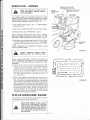
CONGRATULATIONS on your purchase of a Sears Lawn
T ractor. It has been designed, engineered and manufactured
to give you the best possible dependability and performance.
Should you experience any problem you cannot easily reme·
dy, please contact your nearest Sears Service Department.
They have competent, well-trained technicians and the proper
tools to service or repair this unit.
another free manual from www.searstractormanuals.com
Please read and retain this manual. The instructions will enable
you to assemble, operate and maintain your Tractor properly.
Always observe the "RULES FOR SAFE OPERATION".
MODEL
NUMBER ___________________________
SERIAL
NUMBER ____________________________
THE MODEL AND SERIAL NUMBERS WILL BE
FOUND ON THE MODEL PLATE ATTACHED TO
THE FENDER.
YOU SHOULD RECORD BOTH MODEL AND
SERIAL NUMBERS AND KEEP IN A SAFE PLACE
FOR FUTURE REFERENCE.
LIM~TED ONE YEAR W~RRANTY
ON ELECTRIC START RIDING EQUIPMENT
For one year from date of purchase, when this riding equipment is maintained, lubr icated, and
tuned up according to the operating and maintenance instructions in the owner's manual, Sears
will repair free of charge any defect in material or workmanship in this electric start riding equipment.
This warranty excludes blade(s), blade adapter(s), spark plug{s), air cleaner and belt(s), which are
expendable and become worn during normal use.
This warranty does not cover:
tire replacement or repair caused by punctures from outside objects (such as nails, thorns,
stumps, or glass); and
repairs necessary because of operator abuse or negligence, including the failure to maintain the equipment according to instructions contained in the owner's manual; and
· riding equipment used for commercial or rental purposes.
FULL 90-DAY WARRANTY ON BATTERY
For 90 days from the date of purchase, if any battery included with this riding equipment proves
defective in material or workmanship and our testing determines the battery will not hold a charge,
Sears will replace the battery at no charge.
WARRANTY SERVICE IS AVAILABLE BY CONTACTING THE NEAREST SEARS SERVICE
CENTER/DEPARTMENT IN THE UNITED STATES. This warranty applies only while this
product is in use in the United States.
This warranty gives you specific legal rights, and you may also have other rights which vary from
state to state.
Sears, Roebuck and Co., D/698-731A, Sears Tower; Chicago, IL 60684
•
TABLE OF CONTENTS
RULES FOR SAFE OPERATION ...... . ... .. ..3
MAINTENANCE INSTRUCTIONS -MOWER .. . . . 12
ASSEMBLY INSTRUCTIONS .................4
MAINTENANCE INSTRUCTIONS· TRACTOR .. 14
OPERATION INSTRUCTIONS · TRACTOR . .. .. .8
TROUBLE SHOOTING ... ......... . .. . .. . .. 21
OPERATION INSTRUCTIONS · MOWER ....... 11 . 2 . REPAIR PARTS ... .. .......... ... . ........ 24
RULES FOR SAFE OPERATION
WARN lNG: This unit is equipped with an internal combustion engine and should not be used on or near any unimproved forestcovered, brush-covered or grass-covered land unless the engine's exhaust system is equipped with a spark arrester meeting applicable
local or state laws (if any). If a spark arrester is used, it should be maintained in effective working order by the operator.
another free manual from www.searstractormanuals.com
In the State of California the above is required by law (Section 4442 of the California Public Resources Code). Other states may
have similar laws. Federal laws apply on federal lands. See your Sears Authorized Service Center for spark arrester muffler part
number 34479.
23. Use care when pulling loads or using heavy equipment.
a. Use only approved drawbar hitch points.
b. Limit loads to those you can safely control.
c. Do not turn sharply. Use care when backing.
d. Use coun\erweight or wheel weights when suggested in
the owner s manual.
24. Watch out for traffic when crossing or near roadways.
25. When using any attachments, never direct discharge of
material toward bystanders nor allow anyone near the vehicle while in operation.
26. Handle gasoline with care- it is highly flammable.
a. Use approved gasoline containers.
b. Never remove the fuel cap of the fuel tank or add gasoline to a running or hot engine or an engine that has
not been allowed to cool for several minutes after running. Never fill the tank indoors, always clean up spilled
gasoline.
c. Open doors if the engine is run in the garage - exhaust
fumes are dangerous. Do not run the engine indoors.
27. Keep the vehicle and attachments in good operating condition, and keep safety devices in place and working.
28. Keep all nuts, bolts and screws tight to be sure the equip.
ment is in safe working condition.
29. Never store the equipment with gasoline in the tank inside
a building where fumes may reach an open flame or spark.
Allow the engine to cool before storing in any enclosure.
30. To reduce fire hazard, keep the engine free of grass, leaves
or excessive grease. Do not clean product while engine is
running.
31. Except for adjustment; DO NOT operate Engine if air
cleaner or cover directly over carburetor air intake is removed. Removal of such part could create a fire hazard.
32. Do not operate without a muffler or tamper with the
exhaust system. Damaged mufflers or spark arresters could
create a fire hazard. Inspect periodically and replace if
necessary.
.
33. The vehicle and attachments should be stopped and Inspected for damage after striking a foreign object and the
damage should be repaired before restarting and operating
the equipment.
34. Do not change the engine governor settings or overspeed
the engine; severe damage or injury may result.
35. When using the vehicle with mower, proceed as follows:
a. Mow only in daylight or in good artificial light.
b. Shut the engine off when unclogging chute.
c. Oleck the blade mounting bolts for proper tightness at
frequent intervals.
36. Do not operate the mower without the deflector shield in
place.
37. Disengage power to mower before backing up. Do not mow
in reverse unless absolutely necessary and then only after
careful observation of the entire area behind the mower.
38. Under normal usage the grass catcher bag material is subject
to deterioration and wear. It should be checked frequently
for bag replacement. Replacement bags should be checked
to ensu re compliance with the original manufacturer's
recommendations or specifications.
1. Know the controls and how to stop quickly. READ THIS
OPERATOR'S MANUAL and instructions furnished
with attachments.
2. Do not allow children to operate the machine. Do not
allow adults to operate it without proper instruction.
3. Do not carry passengers. Do not mow when children and
others are around.
4. Always wear substantial footwear. Do not wear loose fitting
clothing that could get caught in moving parts.
5. Keep your eyes anq mind on your tractor, mower and the
area being cut. Don t let other interests distract you.
6. Do not attempt to operate your t ractor or mower when
not in the drivers seat.
7. Always get on or off your tractor from the operators left
hand side.
8. Clear the work area of objects (wire, rocks, etc.) which
might be picked up and thrown.
9. Disengage all attachment clutches before attempting to
start the engine.
.
10. Disengage power to attfchments and stop the engme before leaving the operators position.
11. Disengage power to mower, stop the engine and d~sconnect
spark plug wire(s) from spark plug(s) before cleamng, mak.
ing an adjustment or repairs.
12. Disengage power to attachments when transporting or not
in use.
13. Take all possible precautions when leaving the vehicle unattended. Disengage the power-take-off, lower the attachments, shift into neutral, set the parking brake, stop the
engine and remove the key.
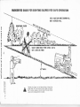
14. Do not stop or start suddenly when going uphill or downhill. Mow up and down the face of slopes (not greater than
150); never across the face. Refer to page 43.
15. Reduce speed on slopes and make turns gradually to prevent tipping or loss of control. Exercise extreme caution
when changing direction on slopes.
16. While going up or down slopes, place Gear Shift Control
Lever in 1st gear position to negotiate the slope without
stopping.
17. Never mow in wet or slippery grass, when traction is unsure or at a speed which could cause a skid.
18. Stay alert for holes in the terrain and other hidden hazards.
Keep away from drop-offs.
19. Do not drive too close to creeks, ditches and public highways.
20. Exercise special care when mowing around fixed objects
in order to prevent the blades from striking them. Never
deliberately run tractor or mower into or over any foreign
object.
21. Never shift gears until tractor comes to a stop.
22. Never place hands or feet under the mower, in discharge
chute or near any moving parts while tractor or mower are
running. Always keep clear of discharge chute.
LOOK FOR THIS SYMBOL TO POINT OUT IMPORTANT SAFETY
PRECAUTIONS. IT MEANS- ATTENTION! BECOME ALERT!
YOUR SAFETY IS INVOLVED.
-3-
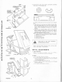
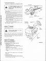
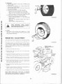
To assemble your Tractor you will need:
two 7/ 16" wrenches, two 9/ 16" wrenches, two 1/2"
wrenches, a 3/4" wrench and a utility knife
NOTE: RIGHT HAND (R.H.) AND LEFT HAND (L.H.) ARE
DETERMINED FROM OPERATOR 'S POSITION WHILE
SEATED ON THE TRACTOR.
ASSEMBLY
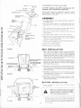
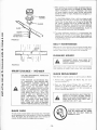
1. Cut down carton at four corners, fold down carton. Remove Bag of Parts.
2. Slide Upper Steering Shaft over Lower Steering Shaft unttl
bolt holes line up with slots in Lower Steering Shaft (Fig.
another free manual from www.searstractormanuals.com
TUBE
1) .
3. Use two Bolts and two Locknuts to retain Upper Steering
Shaft to Lower Steering Shaft. Tighten securely.
4. Sl ide Tube over Steenng Shaft Assembly and over Steering
Sleeve Bracket.
5, Place Steering Wh eel Adapter on Upper Steering Shaft .
LOWER STEERING
SHAFT
6. With front wheels pointed straight ahead, place Steering
Wheel on Steering Wheel Adapter . Bars of Steering Wheel
should point straight across tractor.
7, Place 2 · 114" Dia. Washer on Upper Steering Shaft and in·
stall a 1/ 2" Nut. Tighten securely.
8. Snap Insert into Steering Wheel.
9. Remove plastic on Tractor Hood.
FIGURE 1
SEAT INSTALLATION
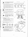
1. Mount Seat Pivot Bracket to Fender using two Hex Bolts
3/8 - 16 x 3/4, two Washers 13/32 x 13/ 16 x 16 Ga. and
two Crownlock Nuts 3 8 · 16 (Fig. 2). NOTE: WASHERS
SHOULD BE POSITI ONED UNDER FENDER NEXT TO
NUTS. Seat Pivot Bracket, Bolts, Washers and Nuts found
in Bag of Parts. Tighten Nuts securely.
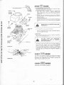
SEAT PAN
2. Mount Seat Pan to Seat Pivot Bracket using two Shoulder
Bolts 5/16 • 18 and two Lock Nuts 5/1 6 - 18 (Fig. 2) (head
of Bolts to outside). Bolts and Lock Nuts found in Bag of
Parts. Tighten Nuts securely.
FENDER
3. Place Seat on Seat Pan. Screw Large Adjustment Bolt,
Lock washer and Flat Washer into Seat (F ig. 3). Adjustment
Bolt, Lockwasher and Flat Washer found in Bag of Parts.
Tighten finger tight.
4. Place Seat in operating position. Sit on the Seat and press
Clutch-Brake Pedal all the way down. If operating position
is not comfortable, adjust Seat.
FIGURE 2
5. Raise Seat. Use 3/4" wrench to loosen Adjustment Bolt
(Fig. 3), When adjusted for comfortable operation, tighten
Adjustment Bolt securely.
BATTERY INSTALLATION
on Ttacto
'o o:. ;~: 3z::e y Otepara·
READ THE INSTRUCTIONS INCLUDED
WITH THE BATTERY ACID CONTAINER .
ALWAYS WEAR CLOTHING TO PROTECT YOUR HANDS AND EYES.
- 4-
a. Remove the vent caps ftom the battery. Fill each cell
wtth actd. Add the ac•d unul •t reach es the bottom of
the vent tube (Fig. 4). Do not add the acid beyond this
level 01 the addt t tonal acid can come out when the bat
tcry IS charged.
~I-========<(
b. Wait 20 to 30 minutes before installing the vent caps. If
the level of acid falls below the point as described in step
a, add more acid until the correct level is reached. Install the vent caps. Wash the top of the battery with
water to remove any acid, then wipe dry.
c. Neutralize excess battery acid for disposal by adding it
to four inches of water in a five gallon plastic container.
Stir with a wooden or plastic paddle while adding baking soda until the addition of more soda causes no more
foam ing,
another free manual from www.searstractormanuals.com
VENT
CAP
CUT AWAY VIEW
WASH HANDS OR CLOTHING IMM EDIATELY IF ACCIDENTALLY IN CONTACT
WITH ELECTROLYTE .
c:::::::J
c:::::::J
c::::::J
VENT
TUBE
; : i-
~
•:
.. :
_. I·
::....::-~~~· :: ~~~-~~~-~-~BATTERY
CELL
FIGURE 4
DO NOT SMOK E. FUMES FROM CHARGED ELECTRO L YTE ARE EXPLOSIVE.
d. Use a 12 volt battery charger. Charge battery at a rate
of 2 amperes for 3 to 4 hours. Check the acid level after
the battery is charged. If the acid has fallen below the
correct level, add water.
DO NOT SHORT BATTERY TERM INALS.
BEFORE I NSTALLING BATTERY, REMOVE METAL BRACELETS, WRISTWATC H BANDS, R INGS, ETC. FROM
YOUR PERSON .
2. Position Battery in tractor as follows:
a. Lift Seat (Fig. 5).
b. Lower Battery into Fender Well with Battery T er·
minals toward front of tractor (Fig. 5). Make sure
Battery rests in Battery Tray (Fig. 6).
FIGURE&
NOTE: BE SURE BATTERY DRAIN TUBE IS SECURELY ATTACHED TO BATTERY TRAY DRAIN .
NEGATIV E
TER MINAL
3. Connect Battery Cables using: two Hex Bolts, two Flat
Washers, two Lockwashers and two Hex Nuts (show n f ull
size below) found in Bag of Parts.
NEGATIVE
CABLE (BLACK)
~~~~
LOCKWASHER
POSITIVE
TERMINAL
./
~
POSITIVE
CABLE (REO)
"
POSITIVE TERMINAL MUST BE CONNECTED FIRST TO P~EVENT SPA RKS
FROM ACCIDENTAL GROUNDING .
a. Connect RED Battery Cable to Positive(+) Battery Terminal with Hex Bolt, ·Flat Washer, Lockwasher and Hex
Nut (Fig. 6). Tighten securely.
b. Connect BLACK Ground Cable to Negative (·) Battery
Terminal with remaining Hex Bolt, Flat Wash er, Lock·
washer and Hex Nut (Fig. 6). Tighten securely.
BATTERY TRAY
FIGURE 6
. 5.
WING
NUT~
INTERNAL/EXTERNAL
(/3!!J
LOCKWASHER
~
TERMINAL
GUARD
4. Insta ll Battery using: two lnt./Ext. Lockwashers, two Wing
Nuts (shown full size below) and
@
WING NUT_1/
INTERNAL/
~
EXTERNAL~
LOCKWASHER
another free manual from www.searstractormanuals.com
m"IIMIGmmnmm[•::::::::::::::::::::::::::::E[)
fs II
SLOT
two Battery Bolts and one Termina Guard 'ound .n Bag of
Parts.
a. Using the slot on one side of the Battery Support (Fig.
6A) slide Battery Bolt into Frame Slot (head of Bolt
down). Fasten the Battery Bolt to the T erminal Guard
using lnt./ Ext. Lockwasher and Wing Nut as shown in
Fig. 6A.
b. Assemble the remaining Battery Bolt to other side of
Battery Support and fasten Terminal Guard to it with remaining lnt./Ext. Lockwasher and Wing Nut. Tighten
Wing Nuts securely by hand (Fig. 6A).
NOTE: USETERMINALACCESS DOORS (FIG.6A) FOR:
1. Inspection for secure connect:ons (t ighten hardware).
2. Inspection for corrosion.
3. Testing battery.
4. Jumping (if required).
5. Charging (if required).
--~_....,~,y
FIGURE 6A
WHEN NOT IN USE , KEEP TERMINAL
ACCESS DOORS CLOSED.
NOTE: DO NOT START ENGINE UNTIL INITIAL SER·
VICE HAS BEEN PERFORMED
INITIAL ADJUSTMENTS
1. TIRE PRESSURE
Reduce T 1re pressure to 14 PSI 1ro front !Ires; 12 PSI n
rear t res. 1T1res were over"nflated for shipping).
FIGURE 7
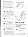
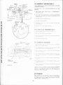
2. HOOD
a. To raise Hood, lift at rear of Hood.
b. To remove Hood, Grill and Side Panels, ra1se Hood and
loosen one screw on each Side Panel. (The screw re mains
in the Side Panei)(F ig. 7).
c. Unsnap Headlight Connection (F g 8 ).
d. Stand in front of T ractor. Grasp Hooc and tIt forward
and lift off (Fig. 8).
e. To reinstall, reverse above procedu·e
FIGURE 8
. 6.
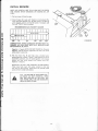
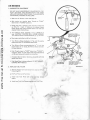
INITIAL SERVICE
NOTE: BE CAREFUL NOT TO ALLOW DIRT TO ENTER
THE ENGINE WHEN CHECKING OR ADDING OIL OR
FUEL.
1. Pull up at rear of Hood to open.
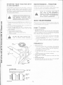
2. Check Engine Oil Level with Tractor on level ground. Remove and wipe Dipstick (Fig. 9) clean, screw it in tight for
a few seconds, remove and read Oil Level. If necessary, add
Oil untii"FULL" mark is reached.
another free manual from www.searstractormanuals.com
RECOMMENDED SAE VISCOSITY GRADES
K
I~
v
30 OR lOW-30
.A
!iW-20 OR 5W·30
"""!
-'l.fP
0°
32°
60°
80°
FIGURE 9
100°
TEWERATURE RANGE EXPECTED BEFORE NEXT OIL
CHANGE. ALL OILS MUST MEET A.P.I. SERVICE CLASSIFICATION SO, SE, OR SF.
Capacity is 1 quart. NOTE: DO NOT OVERFILL. Dipstick
assembly must be securely t ightened into tube at all times
when engine is operating.
3. Fill Fuel Tank (Fig. 9). Use fresh, clean, unleaded auto11
motive gasoline. (Leaded "regular grade gasoline is not an
acceptable substitute. Use of leaded gasoline will increase
carbon and lead oxide deposits and reduce valve life).
Capacity is 5 quarts.
WARN ING : DO NOT USE GASOHOL OR METHANOL.
These type fuels react with water content in the fuel
and tend to form strong acids which can corrode metal
parts and harm rubber and plastics.
FILL TO BOTTOM OF GAS TANK FILLER NECK. DO NOT OVERFILL. WIPE
OFF ANY SPILLED OIL OR FUEL. DO
NOT STORE, SPILL OR USE GASOLINE
NEAR AN OPEN FLAME.
,. .
-7-
.. ... ..
.....
A
CHOKf
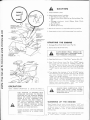
CAUTION
1. Keep all shields in place.
FAST
2. Before leaving operator's position:
a. Shift lever to neutral (F ig. 10).
b. Depress Clutch/ Bra ke Pedal and set Parking Brake (Fig.
10) ..
c. Disengage attachment clutch (Mower Blade Clutch
lever) (Fig. 10).
d. Shut off engine.
e, Remove ignit ion key.
SLOW
another free manual from www.searstractormanuals.com
::<. Wait for all movement to stop before servicing machine.
4. Keep people and pets a safe distance away from machine.
STARTING THE ENGINE
1. Disengage Mower Blade Clutch Lever (Fig. 10).
2. Depress Clutch-Brake Pedal fully.
A
"CLUTCH/BRAKE"
POSITION
FIGURE 10
'-.....__
CLUTCH-BRAKE PEDAL SHOULD REMAIN COMPLETELY DEPRESSED WHEN
FOOT PRESSURE IS RELEASED.
3 . Place Gear Shift Lever in "NEUTRAL" position (Fig. 10).
4. Move Throttle Control Lever (Fig. 10) to "FAST" detent,
then to the right and upward for "CHOKE" position. At
the " FAST" position the Lever has a stop. The stop is provided so that you will know when you are at full throttle
"FAST" position and prevent over travel into choke posi·
tion.
5. Turn Ignition K ey clockwise ( f ' l ) to "START" position
and release Key as soon as engine starts (Fig. 10). lmmedi·
ately move Throttle Control Lever mid-way between
"FAST" and " SL OW" positions.
NOTE: DO NOT RUN STARTER CONTINUOUSLY FOR
MORE THAN FIFTEEN SECONDS PER MINUTE. If
Engine does not start after several a,~tempt~1 move ,Throttl~
Control Lever m1d·way between FAST and SLOW
positions, wait a few minutes and try again.
OPERATION
NOTE: MOWER OPERATION IS LISTED ON PAGE 11.
A
THIS TRACTOR IS EQUIPPED WITH
INTERLOCK SWITCHES TO PREVENT
STARTING OF THE TRACTOR ENGINE
WHILE THE MOWER BLADE CLUTCH
LEVER IS IN THE "ENGAGED" POSITION AND/OR THE FOOT PEDAL IS
NOT FULLY DEPRESSED. IMMEDIATE·
LV REPLACE SWITCHES THAT ARE
NOT IN PROPER WORKING ORDER.
DO NOT ATTEMPT TO DEFEAT THE
PURPOSE OF THESE SWITCHES.
LEARN TO START, STOP AND REVERSE
YOUR TRACTOR IN A LARGE, OPEN
AREA.
l____
-------------J _8 .
A
ALWAYS WEAR SUBSTANTIAL FOOTWEAR AND AVOID LOOSE FITTING
CLOTHING THAT COULD GET CAUGHT
IN MOVING PARTS.
WARMING UP THE ENGINE
Move Throttle Con tr ol lever mid-way bet\veen "FAST" and
"SLOW" positions (Fig. 10). As eng ne warms up, move Throt·
tie Control lever to "FAST" positiOn, NOTE: ALLOW ENGINE TO WARM UP FOR A FEW MINUTES BEFORE
OPERATING.
When restarting a warm engine, move Throttle Control Lever
to "FAST" position, "CHOKE" may not have to be used.
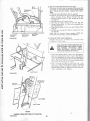
MOWER 'INSTALLATION
CLUTCH
ROD
Your 36" Mower installs without the use of t ools. Raise Lift
Lever (F ig. 11) t o its highest position, Turn Depth Adjustment K nob to lowest position (F ig. 14).
1, Install Front Hinge Pin t hrough Axle and Parallel Link
(Fig. 12). Secure with Retainer Spri ng,
2. Install Rear Hinge Pin through Mower Lift Brackets and
Parallel link (Fig. 12). Secure with Retainer Spri ng.
another free manual from www.searstractormanuals.com
3. Inst all Clutch Rod in Clutch Lever (Fig. 13 - Inset ). NOTE:
INSTALL RETAINER SPRING FROM THE BOTTOM OF
CLUTCH ROD TO AVOID INTERFERENCE WITH
MOWER DRIVE BELT.
[
FRONT
REAR
HINGE
PIN
HINGE
PIN
4 . Move Lift Lever (Fig. 11) forward to lower Suspension
A rms. Slide Trunnions through Lift Bracket holes and
secure with Retainer Springs (Fig. 13).
FIGURE 12
CLUTC H
LEVER
5. Roll Belt over Mower Drive Pulley. Make sure Belt is inside
Belt Guides (Fig, 14). See Belt Drive Schematic Decal on
Mower Housing.
CLUTCH
ROD
6. Use Lift Lever (Fig.11) to raise mower.
NOTE: SEE MOWER ADJUSTMENT, BELOW.
7, Turn Depth Adjustment Knob clockwise ((-"'\ ) to the m iddle of it's travel,
MOWER ADJUSTMENT
FOR ANY ADJUSTMENTS, INSPECTION
OR MAINTENANCE :
PUSH TRACTOR CLUTCH-BRAKE PEDAL COMPLETELY INTO BRAKE POSITION. MOVE GEAR SHIFT LEVER TO
"N" NEUTRAL POSITION. PLACE PARKING BRAKE IN " ENGAGED" POSITION.
SHUT OFF THE ENGINE. PLACE MOWER
BLADE CLUTCH LEVER IN "ENGAGED "
POSITION. MAKE ABSOLUTELY SURE
THE BLADES AND ALL MOVING PARTS
HAVE COMPLETELY STOPPED,
R EMOVE THE IGNITION KEY, DISCON·
NECT THE SPARK PLUG WIR E FROM
THE SPARK PLUG AND K EEP WIRE
AWAY FROM THE PLUG TO PREVENT
INJURY FROM ACCIDENTAL STARTING.
FIGURE 13
NOTE: BEFORE CHECKING THE SIDE TO SIDE AND
FRONT TO REAR ADJUSTMENTS, PAGE 10, BE SURE
PRESSURE IN FRONT T IRES IS 14 PSI AND PRESSUR E
IN REAR T IR ES IS 12 PSI. IF TIRES ARE OVER OR
UNDER INFLATED YOU WILL NOT PROPERLY ADJUST
YOUR MOWER.
DEPTH ADJUSTMENT
FIGURE 14
Adjust ment for mower height is made with the Depth Adjust ment K nob. Raise Mo wer cutting height by turning Depth
Adjustment Knob clockwise ( ~ ). Lower Mower cutting
height by turning Depth Adjustment Knob coun terclockwise
(F'\l .
-9 -
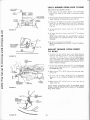
LEVEL MOWER FROM SIDE TO SIDE
LIFT LEVER
PLUNGER
SEE MOWER ADJUSTMENT, PAGE 9.
1. Park tractor on level surface. Depress Lift Lever Plunger
and use Lift Lever to raise mower to maximum cutting
height.
LIFT
LEVER
SIDE-TO-SIDE
ADJUSTMENT
TOP OF
FLANGE
3. If distance "A" needs to be changed, snap out Access Hole
Cover on L.H. side above Footrest- Use 9/ 16" wrench on
Nuts "B" and "c" at Side-To-Side Adjustment Trunnion
(F ig. 16).
another free manual from www.searstractormanuals.com
A
A
FIGURE 15
I
SIDE -TO-SIDE
ADJUSTMENT
TRUNNION
2. Measure height of Top of Flange to level surface at front of
mower. Distance "A" should be the same (Fig. 15).
4. To raise left s1de of mower, loosen Nut
Nut"c"
"s" and
tighten
5. To lower left side of mower, loosen Nut " c " and t ighten
Nut "B".
NOTE: ONE ROTATION OF ADJUSTM ENT NUTS IS
EQUIVALENT TO APPROX IMATELY 3/ 16" HEIGHT
CHANGE.
6. Be sure all nuts are securely tightened.
NOTE: SEE MOWER ADJUSTMENT, FRONT-TO-REAR,
BELOW.
-_J_.llio<...._.,.
NUT"B"
ADJUST MOWER FROM FRONT
TO REAR
1. To obtain the best cutting results, your Mower Housing
should be adjusted so the Front and Rear Flange distance
"D" (F ig. 17) is 5/1 6" lower in front when the mower is
positioned in the t>i~hest cutting position . NOTE: MEAS1
URE DISTANCE D" FROM SURFACE TO RIGHT
REAR FLANG E AND COMPARE TO DISTANCE "D" AT
RIGHT FRONT FLANG E.
FIGURE 16
2. To raise rear of mower, loosen Nut ''E" on both Rear Sus·
pension Arms. Screw both Nuts ''F" up EQUAL NUMBER
OF TURNS (Fig. 18).
3. When distance "D " is 5/16" lower at front than rear, tighten Nut "E".
4. To lower rear of mower, loosen Nut "F" on both Rear
Suspension A rms an EQUAL NUMBER OF TURNS (F ig.
18).
5. When d istance "D " is 5/ 16" lower at front t han rear, ret ighten Nuts "E".
REAR
SUSPENSION
TRUNNION
NOTE: WHEN ADJUSTING REAR SUSPENSION TRUNNIONS, ALWAYS ADJUST BOTH EQUALLY SO MOWER
WILL STAY LEVEL.
FIGURE 17
REAR
SUSPENSION
TRUNNION
NUT "F" -~·"--"
FIGURE 18
-10-
OPERATION - MOWER
READ THE "RULES FOR SAFE OPERATION" CAREFULLY BEFORE OPERATING YOUR MOWER.
MOWER CLUTCH LEVER
"DISENGAGED" POSITION
DEPTH
ADJUSTMENT
KNOB
MOWER CLUTCH LEVER
"ENGAGED" POSITION
THE MOWER MUST BE ADJUSTED PROPERLY FROM
FRONT TO REAR AND LEVELED FROM SIDE TO SIDE
BEFORE OPERATING. THIS IS NECESSARY FOR LEVEL
AND EFFICIENT MOWING. REFER TO PAGE 10.
1. Place Mower Blade Clutch Lever in ''DISENGAGED"
position (Fig. 19).
another free manual from www.searstractormanuals.com
2. Push tractor Clutch-Brake Pedal fully into brake position.
3. Place Gear Shift Lever in ''NEUTRAL" position.
NOTE: TRACTOR MUST HAVE FOOT PEDAL DEPRES11
SED AND MOWER BLADE CLUTCH LEVER IN DISENGAGED" POSITION BEFORE TRACTOR WILL START.
4. Start tractor and set engine speed to about 1/3 to 1/2 throttle before engaging mower. After mower is "ENGAGED"
and you have started forward travel, set to FULL THROTTLE.
NOTE: "ENGAGE" OR "DISENGAGE" MOWER BLADE
CLUTCH LEVER SLOWLY.
FIGURE 19
NEVER " ENGAGE" MOWER EXCEPT
WHEN SITTING ON TRACTOR SEAT.
NOTE: ALWAYS MOW WITH THROTTLE CONTROL IN
"FAST" POSITION. THIS RESULTS IN BETTER GRASS
CUT, BETTER ENGINE COOLING, AND BETTER FUEL
ECONOMY.
5. Use Lift Lever to lower mower into cutting position. Start
mowing in t he fi rst gear and increase ground speed as
conditions w ill permit. Average cutting height is approximately 2 • 1/2 to 2- 3/4 inches. Height of cut can be adjusted by means of the Depth Adjustment Knob (Fig. 19).
Moving the Knob clockwise ( ~) raises the mower (Fig.
)
14 - Inset) . Moving the Knob counterclockwise ( 0
lowers the mower.
6. Drive so that clippings are discharged onto the area that has
been cut. Have the cut area to the right of the machine.
This will result in a more even distribution of clippings and
more uniform cutting. When mowing large areas (Fig. 20)
start by turning to the right so that the clippings will be
discharged away from shrubs, fences, driveways, etc. After
two or three rounds, mow in the opposite direction making
left hand turns until finished. If grass is extremely tall, it
should be mowed twice. The first time cut relatively high.
The second time to the desired height. The left hand side
of mower should be used for trimming.
FLIP-UP DISCHARGE GUARD
Your mower has a f lip-up Discharge Guard (Fig. 19) for door
or gate clearance when held in raised position.
MAKE SURE MOWER BLADE CLUTCH
LEVER IS IN "DISENGAGED" POSITION
AND BLADES HAVE STOPPED BEFORE
RAISING DISCHARGE GUARD (DEFLECTOR). NEVER OPERATE MOWER WITHOUT DISCHARGE GUARD IN OPERATING POSITION.
~--------------------------------------~ -11-
FIGURE 20
1. When grinding, care should be taken t o maintain blade bal·
ance and the blade should be checked for proper balance
before reinstallation on mower. Unbalanced or bent blade
will cause excessive vibration when running, and eventual
damage to mower or engine. Replace bent, damaged or unbalanced blades.
another free manual from www.searstractormanuals.com
To check Blade balance, drive a nail into a beam or wall.
leave about one inch of the straight nail exposed. Place
Center Hole of clean Blade over the head of the nail (Fig.
22). NOTE: CENTER HOLE OF BLADE ON NAIL. IF
BLADE IS PROPERLY BALANCED, BLADE SHOULD
REMAIN IN POSITION SHOWN IN FIG. 22. IF EITHER
END OF THE BLADE MOVES DOWNWARD, BLADE IS
NOT BALANCED AND MUST BE REPLACED.
WASHER----~:o.
2. To ensure satisfactory operation, it is recommended that
before the start of each mowing season, the old blades be
discarded and replaced with new blades. Mower blades can
be purchased at any Sears Service Center/Departments and
most Sears Retail Stores.
LOCKWASHER ~
HEX BOLT GR. 5 - - - . . . . .
FIGURE 21
DAILY MAl NTENANCE
' II~~.
CENTER
HOLE
0
---
Make sure all nuts on bolts are t ight and cotter pins and retain·
er springs are secure. Keep blades sharp. Observe all safety pre·
cautions. Keep mower welllubr cated (refer to page 22).
CLEANING MOWER
DISCONNECT SPARK PLUG WIRE TO
PR EVENT ACCIDENTAL STARTING BE·
FORE CLEANING.
FIGURE 22
Water pressure from a garden hose will remove fresh clippings
from underside of mower. Clean mower after each mowing.
MAINTENANCE - MOWER
FOR ANY ADJUSTMENTS, INSPECT ION
OR MAINTENANCE:
PUSH TRACTOR CLUTCH-BRAKE PED·
AL COMPLETELY INTO BRAKE POSI·
TION. PLACE PARKING BRAKE IN
"ENGAGED" POSITION. MOVE GEAR
SHIFT LEVER TO "NEUTRAL" POSI·
TION. PLACE MOWER BLADE CLUTCH
LEVER IN "DISENGAGED" POSITION.
TURN IGNITION KEY TO "OFF" POSITION. MAKE ABSOLUTELY SURE THE
BLADES AND ALL MOVING PARTS
HAVE COMPLETELY STOPPED. RE·
MOVE THE IGNITION KEY, DISCON·
NECT THE SPARK PLUG WIRE FROM
THE SPARK PLUG AND KEEP WIRE
AWAY FROM THE PLUG TO PREVENT
INJURY FROM ACCIDENTAL STARTING.
BLADE REPLACEMENT
Raise Mower to highest position to permit access to Blades.
1. Remove Bolt, lockwasher and Washer (Fig. 21) (turn
counterclockwise (("\).
2. Place new Blade between Flanges, (the word ''TOP" is
stamped on all Blades to assure proper installation). and
secure with Washer, lockwasher and Bolt previously removed. TIGHTEN SECURELY.
A LWAYS USE GRADE 5 HEAT TREATED
BOLTS TO ATTACH BLADES. CHECK
BOLTS IN BLADES OCCASIONALLY TO
MAKE SURE BOLTS ARE TIGHT. TOR·
QUE BOLTS 30 · 35 FT. LBS.
A GRADE 5 HEAT TREATEDBO LT
CAN BE IDENTI FIED BY THREE
LINES ON THE BOLT HEAD AS
SHOWN AT LEFT.
BLADE CARE
For best results mower blades must be kept sharp. The blacles
can be sharpened with a few strokes of a file or on a grinding
wheel. We suggest they be sharpened after every 15 hours of
mowing. Do not attempt to sharpen while on mower.
. 12.
,__
TRACTOR OPERATION
another free manual from www.searstractormanuals.com
1. Depress lift Lever Plunger at top of Mower Lift Lever and
11
move Lever rearward to its "HIGHEST position (Fig.
23).
2. With engine running and warm place Throttle Control
1
Lever midway between "FAST ' and "SLOW" position.
3. Move Gear Shift Lever to "1ST" Gear (F ig. 24).
4. Release Clutch-Brake Pedal SLOWLY to start forward
movement.
5. If 9,round travel is too slow, move Throttle Control Lever
to 'FAST" position or press Clutch-Brake Pedal to stop
and shift to a different gear. NOTE: ALWAYS SELECT A
GROUND TRAVEL SPEED THAT WILL SUIT THE
TERRAIN AND THE ATTACHMENT BEING USED.
NEVER CHANG E GEARS WHILE TRACTOR IS MOVING.
LIFT LEVER PLUNGER
MOWER LIFT LEVER
" HIGH EST" POSITION
MAKE SURE PARKING BRAKE WIL L
HOLD TRACTOR SECUR E.
FIGURE 23
NEVER PLACE YOUR HANDS OR FEET
IN OR UNDER ANY POWERE D ATTACHMENT OR NEAR ANY MOVING PART
WHILE TRACTOR OR ANY POWERED
ATTACHMENT IS RUNNING.
NOTE: ALWAYS OPERATE ENGINE AT FULL THROTTLE
WHEN MOWING TO ASSURE BETTER MOWING PERFORMANCE, LONG ENG INE LIFE AND PROPER. DISCHARGE OF CUT MATERIAL. REGULATE GROUND
SPEED BY SELECTING A LOW ENOUGH GEAR (FIG.
24) TO GIVE THE MOWER CUTTING PERFORMANCE
PLUS QUALITY OF CUT DESIRED.
DO NOT OPERATE THE MOWER WITH OUT THE DEFLECTOR SHIELD (DISCHARGE GUARD) IN PLACE.
TRACTOR OPERATION ON HILLS
DO NOT DRIVE UP OR DOWN HILLS
WITH SLOPES GREATER THAN 15°
AND DO NOT DRIVE ACROSS ANY
SLOPE. REFER TO PAGE 43.
1. Move Gear Shift Lever to "1 ST" Gear before starting up or
down hills.
2. AVOID STOPPING OR SHIFTING ON HILLS.
a. If slowing is necessary, move Throttle Control Lever to
slower position.
LEAVE ENOUGH ROOM WHEN STOPPING AND STARTING TO ALLOW
SLIGHT TRACTOR ROLL DOWNHILL
AS CLUTCH-BRAKE PEDA L MOVES
THROUGH CLUTCH POSITION.
STOPPING YOUR TRACTOR
1. Push Clutch·Brake Pedal completely into "BRAKE" position.
1
2. Move Gear Shift Lever to 'NEUTRAL" position.
3. Place Park ing Brake in "ENGAGED" position. Raise Parking Brake Lever and hold in "ENGAGED" position (Fig.
24). Release Clutch-Brake Pedal.
4. Move Throttle Control Lever to "SLOW" position.
5. Disengage Mower Blade Clutch Lever.
1
6. Turn Ignition Key to '0FF" position.
REMOVE KEY WHEN LEAVING TRACTOR TO PREVENT UNAUTHORIZED
USE .
BRING TRACTOR TO COMPLETE STOP
BEFORE SHIFTING GEARS.
b. If stopping is absolutely necessary, push Clutch-Brake
Pedal quickly to brake position and engage Parking
Brake.
TRANSPORTING YOUR TRACTOR
c. To restart tractor movement, make sure tractor is in the
lowest speed range t1ST" Gear) and that you have
For pushing or1 towing your tractor, place Gear Shift Lever
1n "NEUTRAL ' position (Fig. 24). Push Clutch-Brake Pedal
allowed room to roll slightly downhill. Depress Clutch11
Brake fully. Disengage Parking Brake and release Clutch·
down firmly to DISENGAGE" Parking Brake (Fig. 24).
Brake Pedal SLOWLY to start tractor movement.
NOTE: DO NOT TOW YOUR TRACTOR FASTER THAN
3. Make all turns gradually
-13 .SIX MILES PER HOUR.
STARTING YOUR TRACTOR WITH
A LOW BATTERY
MAINTENANCE- TRACTOR
If your Battery is too low to start the engine, it should be
recharged. If "Jumper Cables" are used for emerge11cy starting
follow this procedure. NOTE: YOUR TRACTOR ,s EQUIPPED WITH A 12 VOLT NEGATIVE GROUNDED SYSTEM
THE OTHER VEHICLE MUST ALSO BE A 12 VOLT NEGA
TIVE GROUNDED SYSTEM.
-o keep your tractor running better, onger, perform neces·
sary service using the following Maintenance Schedule.
\/lOWER MAINTENANCE IS LISTED ON PAGE 12.
REFER TO "STOPPING YOUR TRACTOR" PAGE 13 AND DISCONNECT
SPARK PLUG WIRE TO PREVENT AC·
CIDENTAL STARTING BEFORE MAKING
ANY INSPECTION, ADJUSTMENT OR
REPAIR (EXC EPT CARBURETOR).
another free manual from www.searstractormanuals.com
LEAD-ACID BATTERIES GENERATE EXPLOSIVE GASES. KEEP SPARKS, FLAME,
AND SMOKING MATERIALS AWAY
FROM BATTERIES. ALWAYS WEAR EYE
PROTECTION AROUND BATTERIES.
DAILY MAINTENANCE
1. Connect each end of the RED Cable to the POSITIVE (+-)
terminals of each battery (taking care not to short against
chassis).
2. Connect one end of the BLACK Cable to the NEGATIVE
H terminal of fully charged battery.
3. Connect the other end of the cable to ENGINE BLOCK
or good CHASSIS GROUND on tractor (away from Gas
Tank or Battery).
4. Disconnect cables in reverse order·
a. Engine Block or chassis of tractor.
b. Negative terminal of fully charged battery.
c. Positive terminals.
Make sure all nuts on bolts are: gnt and cotter pins and retain·
er spn ngs are secure. Observe al safety precautions. Keep tractor well lubricated (refer to page 22).
FIRST~
HOURS
1. CHANGE ENGINE OIL
Changing Oil aher the f1rst two hours will help eliminate
break-in res1due wh1ch m•ght be damaging to your Engine.
NOTE: BE CAREFUL NOT TO ALLOW DIRT TO ENTER
THE EI\IGII\IE WHEN CHANGING OIL.
a Drain Oil w•th Engme warm Unscrew Oil Drain Plug
(F1g. 25) and remove Dipstick. Catch Oil in a suitable
container. Replace Plug.
b. Refill Eng me Oil. See oil chart, page 7. Refill capacity is
1 quart. NOTE: DO NOT OVE RFILL. Replace Dipstick,
DO NOT USE YOUR TRACTOR BAT·
TERY TO START OTHER VEHICLES.
fREQUENTLY
AIR
SCREEN
1. CHECK BATTERY
a E ectro v:e so ut o 1 level ·n !!ach Battery Cell should be
even with bottoms of tubes •n cells (Fig. 26). Add di9'
t 1.ed water if necessary. NOTE. DO NOT OVERFILL.
b Keep Battery and Termmals clean.
c. Keep Battery Bolts tight.
d. Keep Vent Caps ight and small Vent holes in Caps
open.
e. Recharge SLOWLY at 3 amperes if necessary.
2. CHECK TIRE PRESSURE
Tire pressur<? m front Tires should be 14 PSI; rear Tires
12 PSI.
3. CLEAN A I R SCREEN
Air Screen {Fig. 25) must be kept free of dirt and chaff
to prevent Engine damage from overheat'ng.
FIGURE 25
\}oU•T-==A=W=A=Y=V=I=E=W======~r- VENT CAP
c:::=:J
c::::::::J
- 14 .
4. CHECK BRAKE OPERATION
This tractor is equipped with an adjustable disc brake
mounted on the right side of the transaxle (Fig. 27).
DISC BRAKE
another free manual from www.searstractormanuals.com
IF TRACTOR REQUIRES MORE THAN
SIX FEET STOPPING DISTANCE IN
HIGHEST GEAR, THEN BRAKE MUST
BE ADJUSTED.
•
NOTE: WHEN ADJUSTING BRAKES DO NOT MOVE
12-POINT BOLT.
NOTE: A 5/64 INCH ALLEN SET SCREW WRENCH IS
REQUIRED TO ADJUST THE BRAKE.
a. To adjust, tighten Set Screw (Fig. 27) clockwise ( "")
until Disc Brake can not be moved by hand. Now loosen
Set Screw by turning counterclockwise ( f \ ) 1/2 t urn.
NOTE: PARKING BRAKE MUST BE DISENGAGED
AND GEAR SHIFT LEVER IN NEUTRAL WHILE
MAKING ADJUSTMENT.
b, Depress Clutch-Brake Pedal and engage Parking Brake.
c. Measw~. distance between Brake Operating Arm and
Nut A on Brake Rod.
d, If distance is other than 1 · 112'', loosen Jam Nut (Ficr.
11
27) and turn Nut "A" until distance becomes 1 · 1/ 2 •
Retighten Jam Nut against Nut "A".
Road test tractor for proper stopping distance as stated
above. Readjust if necessary.
EVERY
~
NUT
"A''
BRAKE
OPERATING ARM
12-POINT BOLT
FIGURE 27
ENGINE OIL
FILLER CAP
AND D
ICK
AIR CLEANER-COVER
-illllo.
HO URS
CHECK ENGINE OIL LEVEL
FOAM
ELEMENT
DO NOT CH ECK ENGINE OIL LEVEL
WITH ENGINE RUNNING.
c•
Several minutes after stopping Engine, check Engine
Level with Tractor on level ground. Remove and wipe Dipstick clean (Fig. 28), screw it in tight for a few seconds, remove slowly and read Oil level. If necessary, add Oil until
"FULL" mark is reached,
EVERY
~~
HOURS
(EVE RY 15 HOURS IF OPER ATING
IN VE RY DUSTY CONDITIONS)
FIGURE 28
1. CLEA N AIR CLE A NER ELEM ENT (FIG. 28)
a. Open Hood.
b. Snap off Air Cleaner Cover.
c. Remove Foam Element from Air Cleaner Body.
d. Wash Foam Element in liquid detergent and water to
remove dirt.
e, Wrap foam in cloth and squeeze dry.
f. Saturate foam in engine oil, Squeeze to remove excess
oil.
g. Replace Foam Element and snap Cover on Air Cleaner Body.
NOTE: NEVER RUN ENGINE WITH AIR CLEANER
REMOVED.
2. CHANGE ENGINE OIL
The best time to change Engine Oil is at the end of a day's
operation when all dirt and foreign materials are suspended
15 •
in the hot Oil. See oil chart, page 7.
EVERY
1. CLEAN ENGINE COOLING FINS
Keep Engine Cooling Fins free of dust, dirt and oil to pre·
vent Engine damage from overheating.
a. Snap Cover off Air Cleaner (Fig. 29). Remove Hex
H.ead Screw from inside Air Cleaner. Remove t wo
Slotted Head Screws from rear of A ir Cleaner. Pull Ai r
Cleaner off.
b. Remove two Hex Head Screws from front of Blower
Housing. Remove two Hex Head Screws from side of
Blower Housing.
c. Pull Blower Housing off.
Cylinder Head Cover may also be removed. Clean Engine
Cooling Fins wit h a stiff bristled brush or compressed
air.
AIR CLE A NER COVER
SCREW
another free manual from www.searstractormanuals.com
0@ HOURS
WEAR SAFETY GL ASSES IF USING COM·
PRESSED AIR.
HEX HD.
SCREWS
BREAT HER
TUBE
d. To reassemble, reverse above procedure.
NOTE: PRESS BREATHER TUBE INTO BOTTOM OF
AIR CLEANER (FIG. 29)
2. MUFFLER
Do not operate the tractor w ithout a Muffler (Fig. 29) or
tamper with the exhaust system.
SPAR K
PLUG
CYLINDER
HEA D
COVE R
DO NOT TOUCH HOT MUFFLERS,
CYLINDERS OR FINS AS CONTACT
MAY CAUSE BURNS.
- - - - MUFF LER
Periodically clean the muffler area to prevent grass, dirt
and combustible material from accumulating. Damaged
Mufflers or spark arresters could create a fire hazard. In·
spect periodically and replace if necessary. If your engine
is equipped with a spark arrester screen assembly, remove
every 50 hours for cleaning and inspection. Replace if
damaged•
FIGURE 29
''
.030" FEEL ER
GAUGE
EVERY
TI@@ HOURS
The Spark Plug should be changed every 100 hours of operation, or at the beginning of each mowing season. T o remove
the Spark Plug a Deep Well 13/ 16" Socket is required. Set
Spark Plug gap at .030 inch (Fig. 30).
FIGURE 30
EVERY~@@ HOURS
REPLACE AIR CLEANER ELEMENT
- 16-
AS NEEDED
1. CARBURETOR ADJUSTMENT
DO NOT MAKE UNNECESSARY ADJUSTMENTS. FACTORY SETTINGS ARE SATISFACTORY FOR MOST
APPLICATIONS AND CONDITIONS. IF ADJUSTMENTS
ARE NEEDED, PROCEED AS FOLLOWS:
a. Make sure Air Cleaner is clean (see page 15).
another free manual from www.searstractormanuals.com
b. With engine not running, place Throttle at "FAST"
detent (not in "CHOKE'' position).
.;-
c. Check that hole in Throttle Lever and hole in Plate line
up (Fig. 31 - Inset). If holes are not al igned, loosen
Clamp Screw and move Throttle Cable until holes are
aligned. Tighten Clamp Screw.
r-.....)
d. Turn Mixture Screw clockwise (
LIGHTLY to
seat. CAUTION: FORCING WILL CAUSE DAMAGE.
Turn Mixture Screw counterclockwise (I"\) one turn.
e. Start engine and allow to idle for 5 minutes.
f. Turn Mixture Screw clockwise ( ~) until the engine
speed drops. NOTE THE SCREW POSITION.
g. Turn Mixture Screw counterclockwise ( ;-~ ) until the
engine begins to run rough. Set Mixture Screw between
the two positions.
h. Push Throttle Lever to "FAST" detent (not ''CHOKE").
If engine "hunts" or runs rough, make small adjustments
on Mixture Screw until engine runs smoothly.
i. If engine idles too fast or too slow, adjust Idle with Idle
Speed Stop Screw.
j. High Speed Stop is factory adjusted. DO NOT ADJUSTDAMAGE MAY RESULT.
FUEL
FILTER
HIGH SPEED STOP·
FACTORY ADJUSTED
DO NOT ADJUST
IDLE SPEED
STOP SCREW
FIGURE 31
2. REPLACE FUEL FILTER
a. Remove Clamps from fue l lines at f ront and rear of Fuel
Filter (Fig. 31).
b. Pull Fuel Filter out of fuel lines.
c. Install new Fuel Filter with arrow pointing toward
engine.
,..
d. Install new Fuel Line Clamps supplied with Fuel Filter.
-17-
L
3. REPLACE TRACTOR MOTION DRIVE BELT
The tractor Drive Belt may be replaced without tools. Park
the tractor on level area. Engage Parking Brake. NOTE:
BELT INSTALLATION DECAL UNDER LEFT FOOT·
REST.
a. Remove mower. (See Mower Section, page 20).
b. Remove two Retainer Springs from Belt Guide Bracket
below Transaxle Pulley. Remove Bracket (Fig. 32).
c. Swing Belt Guides away from Belt, toward rear of traotor (Fig. 32).
d. Roll Belt over top of Transaxle Pulley.
e. Roll Belt over Engine Pulley and off Idler (Fig. 34).
f. Release Parking Brake. Pull Belt as far as possible over
top of Clutch Pulley.
g. Reset Parking Brake. Pull Belt over top of Clutch Pulley
(Fig . 34).
h. Pull Belt out through Sh ift Gate to remove from tractor (Fig. 33).
Install Belt by reversing above procedure. NOTE: REPLACEONLYWITH BELT LISTED IN MANUAL.
another free manual from www.searstractormanuals.com
TRANSAXLE
PULLEY
r1
RETAI NER
SPRING
I
BELT GUIDE
BRACKET
RETAINER
SPRING
4. CLEAN BATTERY AND TERMINALS
Corrosion and,, dirt on the Battery and Terminals cause
11
the Battery to leak power.
FIGURE 32
LEAD·ACID BATTERIES GENERATE EXPLOSIVE GASES. KEEP SPARKS, FLAME,
AND SMOKING MATERIALS AWAY
FROM BATTERIES ALWAYS SHIELD
YOUR EYES AROUND BATTERIES.
a. Disconnect BLACK Battery Cable then RED Battery
Cable and remove Battery from Tractor. Wash Battery
w ith four tablespoons of baking soda to one gallon of
water. NOTE: BE CAREFUL NOT TO GET THE SODA
SOLUTION INTO THE CELLS. Rinse the Battery w ith
plain water, dry and reinstall on Tractor.
b. Clean Terminals and Battery Cable ends with a wire
brush until bright. Replace Battery Cables, connecting
RED Battery Cable to Positive Terminal first, then
BLACK Battery Cable to Negative Terminal. Coat ter·
minal connections with Vasoline.
SHIFT GATE
FIGURE 33
l.H. SIDE
BELT GUIDE
REAR
VIEWED FROM BOTTOM OF TRACTOR
FIGURE 34
- 18.
•
another free manual from www.searstractormanuals.com
5. TI RE CARE
a. Maintain tire pressure in front tires at 14 PSI and rear
tires at 12 PSI.
b. Keep tires free of gasoline, oil, or insect control chemicals which can destroy rubber.
c. Avoid stumps, stones, deep ruts and other hazards that
may cause tire damage.
d. Removing front wheel for tire repair (Fig. 35).
-- Block up front axle securely. Pull ott Dust Cap.
-- Remove Klip Ring and Washer and remove wheel.
-- Repair tire and reassemble. Replace Washer, snap
Klip Ring securely in axle groove. Replace Dust Cap.
e. Removing rear wheel for tire repair (Fig. 36).
-- Block up rear axle securely. Pull off Dust Cap.
-- Remove E-Ring and Washers (1 to 3 as required) and
remove wheel.
-- Repair tire and reassemble. Replace Square Key in
Axle Shaft.
- Replace Washers, E-Ring and Dust Cap.
OUST
CAP
FIGURE 35
WHEN MOUNT ING TIR ES, UNLESS
BEADS A RE SE ATED, OVER I NFLAT ION
CAN CAUSE AN EXP LOSION.
6. FINISH
Keep tractor finish and seat free of gasoline, oil, insect
chemicals or battery electrolyte. Protect painted surfaces
with automotive type wax.
MOWER BE LT ADJUST MENT
Your tractor has been manufactured With the ability to re·adjust mower drive belt to provide you with longer belt life.
FIGURE 36
If the Mower Clutch Lever (Fig. 37) travels 3 • 1/2" up the slot
in the dash before spring tension resistance is evident, adjustment is necessary. NOTE: CHECK FOR PROPER SPRING
TENSION WITH ENGINE OFF AND LIFT LEVER IN HIGH
EST POSITION.
MOWER C LUTCH
LEVER "DISENGAGED"
POSITION
1. Remove mower deck from tractor.
2. Remove Cotter Pins from both sides of the Rock Shaft
Assembly (Fig. 38).
3. Loosen the 4 Locknuts on the R.H. and L.H. Pivot Brackets
(Fig. 38) only until Rock Shaft Assembly can be rero1oved.
4. Remove Rock Shaf< Assembly from R.H. and L.H. Pivot
Brackets. NOTE: DO NOT DISASSEMBLE BRAKE ROD.
5. Remove Extension Spring from lower hole (original posi·
tion) in Rock Shaft Assembly and msert in upper hole in
Rock Shaft Assembly (Fig. 38- Inset).
6. Replace Rock Shaft Assembly between R.H. and L.H. Pivot
Brackets.
7. Tighten Locknuts securely making sure Carriage Bolts are
seated in square holes of mower housing.
8. Replace Cotter Pins on both sides of Rock Shaft Assembly.
NOTE: WHEN INSTALLING A NEW BELT, EXTENSION
SPRING MUST BE RETURNED TO LOWER HOLE (ORIGINAL POSITION) ON ROCK SHAFT ASSEMBLY.
FIGURE 37·
· 19 .
TO REMOVE MOWER BELT
IDLER BELT
GUIDE
NOTE: MOWER BELT INSTALLATION DECAL LOCATED
ON MOWER HOUSING.
REPLACE ONLY WITH THE BELTS SPECIFIED IN THIS
MANUAL.
1. Place Mower Blade Clutch Lever in ''DISENGAGED"
posation (Fig. 37).
2. Turn Depth Adjustment Knob to lowest position. Move
Mower Lift Lever (Fog. 37) forward to lower Mower to its
lowest positaon.
another free manual from www.searstractormanuals.com
3. Roll Belt off Engane Pul ley (F g. 38).
FIGURE 38
4. Pull Belt off both Mandrels.
LOWER HOLE
(ORIGINAL
POSITION)
/~
/
SPRING
(
/~
__.-.,..
BRAKE
ROD
5. Spnng Belt Guide away from Idler Pulley and pull Belt
off Idler Pulley.
UPPER HOLE'
-'"'
R.H. PIVOT
~
~ ~1
~
6. Slide Belt fr om under Extension Spring.
0
:)
-
•
TO REPLACE MOWER BELT
·
l -7 _
l H PIVO l BR\ E T
1 Slide B It under Ext
LOCKNUT
2. Place Be t on ea
son Spr ng (F g. 38).
:ie of both Mandrels.
3. Sp "9 Idler Be t Gu de down and olace Belt around rear
s de of Idler Pul ey.
LOCKNUTS
4. Rol Belt over Eng ne Pulley.
TO REMOVE MOWER
1. R rraove IT'Owcr B
per '"lst•t.ct ons under " To Remove
'Vlower Belt", through step 3.
2. Tu•n Depth Ad ustment Knob to owest oosition. Use Lift
Lever to ower mower o ats lowest position.
3. Rer ovc R laaPeo S r ng from Clutch Rod; pull Clutch Rod
out of Clutch 61 ack .
4 Pul Reta111e1 Sprangs out of Rear Suspensoon Trunnions.
Rerraove R ar Suspens on Trunn1ons from Lift Brackets
(F q. 39).
5. Pu
1-1
REAR
SUSPENSION
TRUNNI ONS
Retol ne Sp
p '1 ,
g Out of Rear Hmge Pin, Remove Rear
6. Pu
Reta ne• Sp gout cf Fron t Hinge P n. Remove Front
H nge Pm (Fag. 39).
LIFT
BRACKET
7. Use L1ft Lever to
sc Suspens1on Arms. Sl de mower out
from under tractor.
FIGURE 39
NOTE: IF AN ATTACHMENT OTHER THAN THE MOWER
DECK IS TO BE MOl.JNTED ON THE TRACTOR THE L.H.
AND R.H. SUSPENSION ARMS (FIG. 39) SHOULD BE
REMOVED FROM TRACTOR.
STORAGE
When mower is to be stored for a period of time, clean it
thoroughly, remove all dirt, grease, leaves, etc. Give blades
and underside of housing a good coat of grease or rust preventative. Store in a clean dry area.
-20-
--0
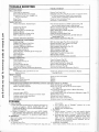
TROUBLE SHOOTING
another free manual from www.searstractormanuals.com
POSSIBLE CAUSE
WILL NOT START
Foot Pedal not depressed
Mower Blade Clutch lever engaged
No gasoline in Fuel Tank, clogged Fuel
line, or Fuel Filter
Blown Fuse
Dead Battery
HARD TO START
Choked improperly, flooded Engine
.
,
Clogged Fuel System
Dirty Air Cleaner
Spark Plug dirty or improper gap
Defective Battery
Defective Ignition or loose wiring
Water in gasoline or old fuel
Improper Carburetor adjustment
ENGINE MISSES OR LACKS POWER
Engine overload
Clogged Fuel Tank or Fuel Filter
Partially plugged Air Cleaner
Improper Carburetor adjustment
Dirty Engine Air Screen
low oil level or dirty oil
Spark Plug dirty, improper gap or wrong type
Faulty ignition
Poor compression
Oil in gasoline
ENGINE OVERHEATS
Dirty. Air Screen
low oil level or dirty oil
Dirty Engine
Partially plugged Muffler
Partially plugged Air Cleaner
Stale fuel or improper Carburetor adjustment
NO LIGHTS
No Headlights with light Switch on and
Engine running
WON'T CHARG E
Blown Fuse
Defective Battery
Defective Diode Assembly
Defective Al ternator
4
POSSIBLE REMEDY
Depress Foot Pedal fully
Disengage lever (Fig. 10). Be sure lever is in bottom of slot
Fill Tank with Gasoline. Check Fuel line and Car·
buretor (clean if necessary) . Replace Fuel Filter.
Check for fault and replace Fuse
Recharge or replace Battery
Place Throttle Control in "FAST" position (Fig. 10)
and run starter several times to clear out gas
Remove and clean Tank and lines. Replace Fuel Filter
Remove and clean (Fig. 28)
Clean, adjust gap or replace (Fig. 30)
Recharge or replace
Check the wiring and Spark Plug
Drain Fuel Tank and Carburetor, use fresh fuel and
replace Spark Plug
Make necessary adjustments (Fig. 31)
Shift to a lower gear (Fig. 24) or reduce load
Remove and clean Tank; replace Fuel Filter
Remove and clean (Fig. 28)
Make necessary adjustments (Fig. 31)
Clean Air Screen (Fig. 25)
Add or change oil (page 14)
Replace Spark Plug (Fig. 30)
Check Spark Plug and for loose wires
Major Engine overhaul
Drain Gas Tank and Carburetor and refill
Clean Air Screen (Fig. 25)
Add or change oil (page 14)
Clean Engine Cooling Fins (page 16)
Remove and clean Muffler or replace
Remove and clean (Fig. 28)
Use fresh fuel and adjust Carburetor (Fig. 31)
Check Fuse, Switch and wire connections. Replace
Headlight Bulbs
Check for fault and replace
Replace
Replace
Replace
UNSATISFACTORY MOWER PERFORMANCE/UNEVEN DISTRIBUTION OF CLIPPINGS
Tires not inflated properly
Check air pressure in tires (page 6)
Check front to rear and side to side mower adjust·
Mower improperly adjusted
ment (page 10)
Grass high or wet
Use a slower ground speed (refer to Mower Operating
Instructions, pa~e 11)
Incorrect engine RPM's
Check engine RPM s (refer to Carburetor Adjustment, page 17)
Excessive wear to outer cutting tip of mower blade
Replace mower blade
Improper mower blade insJallation
Reinstall with top of blade up
Incorrect mower blade
Replace with proper mower blade
Belt slippage
Re-adjust mower drive belt (page 19)
STORAGE
into cylinder.
1. FUEL SYSTEM
1
c. Turn ignition key to 'ST ART" position for a few
a. Drain fuel tank and carburetor by allowing the engine to
run out of gasoline. NOTE: GASOLINE LEFT IN
seconds to distribute oil.
d. Replace with new Spark Plug.
YOUR ENG INE WILL LEAVE GUM DEPOSITS CLOG·
4. BATTERY
GING FUEL SYSTEM.
b. Dispose of gasoline if not to be used. NOTE: GASO·
a. Remove battery if tractor is not used regularly during
winter months. Store in cool, dry place (above 50•F .) .
LIN E STORED FOR SEVERAL MONTHS LOSES ITS
b. Re-charge each month if necessary. NOTE: BATTERIES
VOLATILITY (ABILITY TO BURN EFFECTIVELY).
2. ENGINE OIL
NOT IN USE FOR SEVERAL MONTHS AND NOT
Drain (with engine warm) and replace w ith clean engine oil.
KEPT FULLY CHARGED, PRODUCE SULPHATE
(See chart, page 7).
DEPOSITS ON PLATES WHICH CANNOT BE RE·
3. CY LINDE R
MOVED BY RECHARGING.
a. Remove Spark Plug.
5. GENERAL CLEANING
b. Pour one ounce of engine oil through spark plug hole. 21 • Clean engine, battery, finish, seat, etc. of all foreign nH.llte•
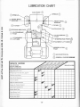
LUBRICATION CHART
AXLE PIVOT
Q)
CD SPINDLE
SPINDLE
CD
FRONT WHEEL f2\
BEARING
\V
another free manual from www.searstractormanuals.com
TIE ROD
G)
CLUTCH PIVOT
CD
CLUTCH/BRAKE f.j'\
PIVOT
\.V
{.;'\ ATTACHMENT
STEERING ROD PIVOT
\.V LIFT ARM
A TTACHM ENT ll FT ARM
CD
G)
MOWER CLUTCH f.j\
PIVOT
\..!...)
G) SAE 30 MOTOR OIL
0
SERVICE RECORD
FILL IN DATES
AS YOU COMPLETE
REGU LAR SERVICE
Check Engine Oil Level
Change Engine Oil (see chart, page 7)
Lubricate Pivot Points
Check Brake Operation
Clean Air Screen
~
.,,.,
,,
~s
'10~
Check Battery Level
Check Tire Pressure
Replace Fuel Filter
o-.J
~ <(,....J<(,.~ <(,....J<(,.~ <(,....J<(,.~
.
,fill"
.,
I~
Replace Air Cleaner Element
Replace Spark Plug
'10~
o-.J
~ 1,':>~~ ':>(;:) ~~ \(;:Jf;;:j Y'--t '),(;:)(;:) Y'
Clean Air Cleaner Element
Clean Engine Cooling Fins
GENERAL PURPOSE GREASE
fl'
.,
*'
1.-"
~
-22 -
SERVICE DATES
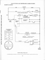
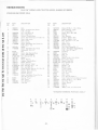
10 H.P. 36" RIDING LAWN TRACTOR--MODEL NUMBER 917.255723
SCHEMATIC DIAGRAM
BATTERY
r---------------R~E~D--------------~Ijr-----------~B~L~A=C~K-------------,
12V
STARTER
RED
RED
another free manual from www.searstractormanuals.com
NEUTRAL INTERLOCK SWITCH
RED
r-a~---+-0
FUSE
30AMP.
B
SOLID STATE
IGNITION
IGN IT ION
SWITCH
PLUG
L
G ~~~----------------------------------------~
IGNITION SWITCH
STD365402
POSITION
CI RCUIT
RECTI FIER
RED
OFF
M-G
ON
B·L
START
B.S
3 AMPS, DC
20 VOLTS, AC (MIN.)
AT 3600 RPM, BATTERY IN LINE
HEADLIGHT
ORANGE
BROWN
LIGHT SWITCH
HEADLIGHT
YELLOW
CHASSIS
GROUND
WIRING INSULATED CLIPS
If Insulated Clips were removed for servicing of unit, they should be replaced to properly secure your wiring.
"23 ·
~
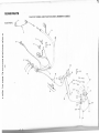
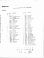
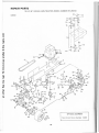
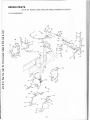
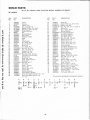
REPAIR PARTS
10 H.P. 36" RIDING LAWN TRACTOR--MODEL NUMBER 917.255723
ElECTRICAl
~
another free manual from www.searstractormanuals.com
2
6
·~ a-- 32 \ ' '
---------...a!,
n:l,v
4~
~
::/~~
"".
N
II
J)
9
·..
23
~28
~
I
24
another free manual from www.searstractormanuals.com
--
~~,~==~~------~
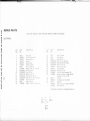
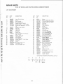
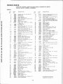
REPAIR PARTS
10 H.P. 36" RIDING LAWN TRACTQR .. MODEL NUMBER 917.255723
ELECTRICAL
N
U1
KEY
NO.
PART
NO
D E:SCH I PTION
KEY
NO.
PArn
NO.
1
2
3
4
5
6
7
8
9
10
11
12
13
14
15
16
7662J
105386X
108379X
105613X
105381X
104445X
3258J
11151000
STD365402
STD380300
STD551125
STD541225
STD522505
73510400
4560J
11 050400
Bull>, Liuht
17
18
20
21
22
23
24
25
26
27
28
/19J
5114.1
2033J
STD522501
STD5!:i1025
STD541 025
104923X
105371 X
STD541625
11030400
72240460
29
31
32
7008J
106580X
7192J
101539X
1083/SX
Harness, Light Socket
Harness, l!lflll.lon
Key Set
Switch, ligh t
Switch, Interlock
Nut, Hex 5/8- 32
Washer, Lock, Int. Tooth, 5/8
Switch, Ignition
• Fuse, 30 Amp.
·washer, Lock, 1/4
·Nut, Hex Jam 1/4 20
• Bolt, Hex, 1/4 · 20 x 1/2 Gr. 5
Nut, Keps 1/4 · 20
Cable Assembly
Washer Lock, Ext. Tooth, 1/4
Cover, Terminal
Cable, Battery
Cable, Battery
'Bolt Hex. 1/4 · 20 x 3/4
•washer 9/32 x 5/8 x 16 Ga.
• Nut, Hex 1/4 · 20
Battery, 12V., Sears
Terminal Guard
·wing Nut 1/4 • 20
lnt../Ext. Tooth Lockwasher 1/4
Battery Bolt (Bolt · Carriage, Rd. Hd.
Sq. Neck 1/4 · 20 x 7 · 1/2)
Solenoid
K1t, Replacement Fuseholder
Cdhle Tie
Sheet · Instruction, Tractor 15° Slope
Owners Manual
"STANDARD HAJ:iDWARI:: -PURCHASE LOCALLY
8
A
<[y
@
11 y~
12
J 13
.w.}16
~14
..
DESCR IPTION
c
·~_}} 16
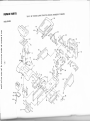
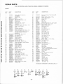
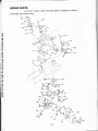
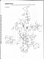
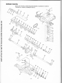
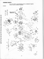
REPAIR PARTS
10 H.P. 36" RIDING LAWN TRACTO R--MODEL NUMBER 917.255723
_,--34
another free manual from www.searstractormanuals.com
ENCLOSURE
49
33
42
52
N
Cl
~
,,
- ~-
,~
45-~
\'
I
A A
.-
~
47 - ..
.._~
461
'f.r..A
~
•
14
~
.-/1
/
I~
f
-·
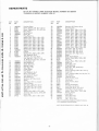
REPAIR PARTS
~--
10 H.P. 36" RI D ING LAWN TRACTOR--MODEL NUMBER 917.255723
another free manual from www.searstractormanuals.com
ENCLOSURE
KEY
NO.
1
2
3
4
5
6
7
8
9
10
11
12
13
N
~
14
16
17
18
19
20
21
22
24
25
26
29
30
32
PART
NO.
DESCRIPTION
Seat
Screw, Hex Washer Thd. Roll 3/8 °
16 x 3/4 Type TT
Screw, Hex Washer Thd. Rolling
17490616
3/8 ° 16x1
Bracket · Pivot, Seat
105513X
Bolt, Shoulder, 5/16 · 18
105529X
Nut, Lock, 5/16 ° 18
73680500
Spring ° Compression
1055 12X
Clamp, Spring
105514X
Fender
105274X
19131312
Washer 13/32 x 13/16 x 12 Ga.
STD523707 * Bolt, Hex, 3/8 ° 16 x 3/4
Nut, Lock 3/8 · 16
73680600
Screw, Hex Washer Thd . Roll 3/8 °
17490608
16 X 1/2
Bracket, Fender
105753X
Footrest. L.H .
105465X
Footrest, R.H.
105464X
STD533707 *Bolt, Carr. 3/8 · 16 x 3/4
Pad, Footrest
105466X
Bracket, Pivot, Grill, R.H.
108504X
Bracket, Pivot, Grill, L.H.
108505X
Pal Nut 1/4 ° 20
108067X
Lens, L.H.
108361X
Lens, R.H.
108360X
STD551 037 *Washer 13/32 x 13/16 x 16 Ga.
Bezel
105268X
Strap Assembly, Grill
105685X
Hinge, Hood, L.H.
105797X
105841X
17490612
A
c
B
·~2 ~ 5
®
6
DESCRIPTION
KEY
NO.
PART
NO.
33
34
35
36
37
38
39
40
41
42
45
46
47
48
49
50
51
52
53
54
55
56
58
59
60
61
63
64
65
66
67
68
Hinge, Hood, R.H.
105792X
Hood Assembly
105682X
Grill Assembly
105678X
Bracket, Frame, Pivot, R.H.
108500X
Bracket, Frame, Pivot, L.H.
108501X
Side Panel , R.H.
106927X
Side Panel, L.H .
106929X
Chassis Assembly
108168X
Drawbar
102481X
Pan· Seat
105516X
Tray, Battery
105372X
Tube· Plastic
105687X
Clamp, Hose
6999R
Decal · Reflective, Rear
105801 X
Decal, Stripe, L.H .
105802X
Decal, Stripe, R.H ..
105803X
Decal, Grill Craftsman
105806X
Decal, Grill, Stripe
105807X
Decal, Clutch/Brake
4900J
Decal, 10 H.P.
105804X
Decal, 4 Speed, 38"
105808X
Decal, V ·Belt Schematic
105813X
Bolt, Hex 1/2 · 13 x 3/4
74780812
Washer · Lock Light 1/2
10110800
Washer 17/ 32 x 1 ° 3/16 x 12 Ga.
19171912
STD52371 0 • Bolt. Hex 3/8 ° 16 x 1
Gu1de Belt, Lower, Eng. Pulley, L.H.
106301X
Guide Belt, Lower, Eng. Pulley, R .H.
106300X
Decal• Stripe, Side Panel, L.H.
106811X
Decal Stripe, Side Panel, R.H.
106812X
Decal Opei ° Caution
106974X
Washer 13/32 x 1 ° 1/4 x 12 Ga.
19132012
*STANDARD HARDWARE--PURCHASE LOCALLY
D
0
0
0
0
0
K
G
·F
M
L
22
tr 11 ~ 13
1J ~ ~ 58~
6) 26
® 12
e
18
61
12
@ 59 ~ 10
®60®12
~3
..:--------
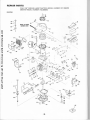
REPAIR PARTS
10 H.P. 36" RIDING LAWN TRACTOR--MODEL NUMBER 917.255723
another free manual from www.searstractormanuals.com
DRIVE
70
56
65
64
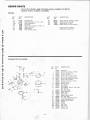
OPTIONAL EQUIPMENT
Spark Arrester Screen Assembly
-28-
34479
REPAIR PARTS
10 H.P. 36" RIDING LAWN TRACTOR --MODEL NUMBER 917.255723
DRIVE
KEY
NO.
DESCRIPTION
PART
NO.
another free manual from www.searstractormanuals.com
108730X
2
3
4
5
6
7
8
9
11
12
13
14
15
16
19
105731X
6404J
STD551143
74770728
105732X
13280312
13200300
31927
17490620
105640X
106342X
105831X
105701 X
17490640
108228X
20
21
22
23
24
25
26
27
28
STD523727
73680600
STD&80025
105703X
12000028
3723J
STD523710
STD523712
17490512
29
30
31
32
33
34
35
36
37
38
39
40
41
42
43
44
45
46
47
105638X
105639X
106903X
4921H
106190X
STD523107
73680500
106294X
106904X
105842X
STD523707
19252516
106933X
105699X
73960500
STD551137
STD561210
19151216
104777X
Engine, 10 H.P., Model No<
143.366062
Pulley, Engine
Spacer
*Washer, Lock, 7/16
Bolt, Hex 7/16 · 20 x 1 · 3/4
V-Belt, Drive
Nipple, Pipe
Elbow, Std. 3/8-18 NPT
Plug, Pipe
Screw, Hex Washer, 3/8 · 16 x 1 · 1/4
Strap, Torque, Engine
Spacer
lsomount Assembly
Washer · Shift, Plate
Screw, Hex Washer, 3/8 · 16 x 2 · 1/ 2
Transaxle, 4 Speed, Model 4150·12
(See pages 36 and 37 for parts
breakdown)
*Bolt, Hex 3/8 · 16 x 2 · 3/4
Nut, Lock 3/8 · 16
• Key, Woodruff
Pulley, Transaxle
Ring, Retainer
Bracket, Transaxle
"Bolt, Hex 3/8 · 16 x 1
• Bolt, Hex 3/8 · 16 x 1 · 1/4
Screw, Hex Washer Thread Rolling
5/16·18 X 3/4
Bracket, Support
Support, Battery
Keeper, Belt, L.H.
Retainer, Spring
Clamp
*Bolt, Hex 5/16 · 18 x 3/4
Nut, Lock 5/16 • 18
Strap, Locator
Keeper, Belt, R.H.
Strap, Torque, Transaxle
*Bolt, Hex 3/8 · 16 x 3/4
Washer 25/32 x 1 • 9/16 x 16 Ga.
Knob, Control
Rod, Shifter
Nut · Lock, Whiz 5/16 · 18
*Washer • Lock 3/8
*Cotter Pin, 1/8x 1
Washer 15/32 x 3/4 x 16 Ga.
Retainer, Belt
DESCRIPTION
KEY
NO.
PART
NO.
48
17490612
49
50
51
52
53
54
55
56
57
58
59
60
61
62
63
64
65
66
67
68
69
70
71
72
73
74
75
76
77
78
79
19131312
105730X
106191X
4470J
4859J
106298X
105705X
STD523715
105709X
207J
12000039
105710X
76020412
105724X
105752X
106888X
73350600
73930600
105758X
71673
105720X
8883R
19252016
STD571810
106918X
STD580025
STD580105
104757X
59192
65139
106268X
7152J
106108X
105702X
12000001
STD533707
106319X
106320X
106157X
105706X
106499X
106299X
2751 R
105700X
106919X
80
81
83
88
89
90
91
92
93
94
95
96
97
Screw, Hex Washer Thd. Rolling 3/8 ·
16 X 3/4
Washer 13/32 x 13/16 x 12 Ga.
Keeper, Belt, Engine
Keeper, Belt
Spacer
Idler, Flat
Pulley, Idler
Bellcrank Assembly (Inc. Key No. 92)
*Bolt, Hex 3/8 · 16 x 1 · 1/2
Spring, Return, Clutch
Washer, Hardened
Ring, Klip
Link, Clutch
Pin, Cotter 1/8 x 3/4
Bracket, Clutch
Rod, Brake
Spring, Rod, Brake
Nut • Jam 3/8 · 16
Nut, Lock 3/ 8 · 16
Rod, Brake, Parking
Cap · Plunger
Shaft, Foot Pedal
Cover · Pedal
Washer 25/32 x 1 · 1/4 x 16 Ga.
• Pin, Roll, 3/ 16 x 1
A rm, Brake
• Key, Woodruff
• Key, Square 3/16 x 2
Cap, Hub, Rear
Cap, Valve
Stem, Valve
Ti r~. Rear. l-9 x 9.-W x 8
Tube, Tire (not furnished with tractor)
Rim Assembly, Rear
Spacer, Split
E-Ring
• Bolt Carriage 3/8 · 16 x 3/4
Spring · Ext.
Bracket o Spring
Plate · Strap, Torque
Bearing
Retainer· Belt
Strap • Ground
Clip · Insulated
Spring, Torsion
Plate, Shift, Rod
*STANDARD HARDWARE--PURCHASE LOCALLY
A
c
B
~20 W WYJ
26
~21
E
D
21
28
F
~ 34 ®21
@35
®21 ®21
G
Gf/39
v w lf
J
H
@21 @
48
26
88
49 @49 ®21
~
·29-
L
21
n
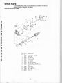
REPAIR PARTS
10 H.P. 36" RIDING LAWN TRACTOR--MODEL NUMBER 917.255723
another free manual from www.searstractormanuals.com
STEERING AND FRONT AXLE
37
l..ool----45
~51
32
\
67
60
621.61 65
~64
55
. 30 -
REPAIR PARTS
10 H.P. 36" RIDING LAWN T RACTOR --MODEL NUMBER 917.255723
STEERI NG AND FRONT AXLE
KEY
NO.
1
another free manual from www.searstractormanuals.com
2
3
4
5
7
8
9
10
11
12
13
15
16
17
18
19
20
21
22
23
24
25
26
27
28
29
31
32
33
34
35
PART
NO.
KEY
NO.
PART
NO.
36
37
38
39
40
41
42
43
44
45
46
47
48
49
19212016
105641 X
2882J
74580
71208
106127X
105663X
105664X
74761 060
105669X
105725X
105726X
73901000
17490508
DESCRIPTION
105620X
74180512
Dash
Screw- Truss Hd, Cross Recess
5/1 6 - 18 X 3/4
Nut- Lock 5/16 • 18
73680500
Decal - Dash Panel
105800X
108593X
Control · Throttle Cable
Screw- Hex Thread Cut 1 4- 20 x 1 '2
17720408
108456X
Decal - Dash Lower
Dash· Lower
105621X
Decal - Caution
106199X
Screw- Hex Washer Hd. Thread Cut.
17190508
5/16 - 18 X 1 - 1/2
105742X
Saddle
17490608
Screw - Hex Washer Hd, Thread
Rollin g 3/8 - 16 x 1/2
Clip
2751R
105810X
Decal - Cap, Steermg Wheel
Insert- Steering Wheel
100710L
STD541350 • Nut- Hex Jam 1/2-20
Washer
100712K
Wheel - Steering
100713N
Adapter - Steering Wheel
100711L
105647X
Sleeve - Steering
105643X
Shaft - Steering Upper
STD523712 "'Bolt - Hex 3/8- 16 x 1 - 1/4
73680600
Nut - Lock 3/8- 16
Screw -Hex Self Tap. No. 10- 16 x 1/2
17431008
105646X
Bracket- Sleeve, Steering
1554J
Bushing Steering
102531X
Bracket- Steermg
17490612
Screw- Hex Washer Thread Rod1ng
3/8 • 16 x 3/4 Type TT
6266H
Bearing Thrust
4301J
Gear- Sector
Key - Woodruff
106126X
Klip Ring
12000029
DESCRIPTION
Washer 21/32 x 1- 1/4 x 16 Ga.
Shaft - St eering - Lower
Pin - Drive 3/16 x 1
Spacer .627 x .88 x .695
Bushing
Rod - Steering
Support - Saddle - Rear
Support- Saddle · Front
Bolt - Hex 5/8 - 11 x 3 - 3/4
Axle- Front
Spacer · Axle
Bearing · A xle
Nut - Lock, Flange 5/8 11
Screw- Hex Washer Thread Rolling
5/16 · 18 x 1/2 Type TT
Klip Ring
12000029
3366R
Beanng
105715X
Rod- Tie
102792X
Bushing
Washe 13/32x7J8x16Ga.
19131416
STD561 210 • Pin • Cotter 1/8 x 1
STD551 137 *Washer - Lock 3/8
STD541137 "Nut - Hex 3/8 - 24
105727X
Link- Drag
Spindle- L.H.
105656X
105654X
Spindle- R.H.
278H
Fitt ng- Grease
9040H
Bean ng • Flange
Rim 6"- Front
106732X
Cap Valve
59192
Stem- Valve
65139
106217X
Tire Rib 15 x 6.00-6
Tube- l=ront (not furn shed w th tractor)
59904
Washer 25/32 x 1 · 1 4 x 16 Ga.
19252016
Cap • Hub - Front
104757X
Screw - Spec1al
106909X
Washer
106910X
Cl ip- U
106911 X
11150500
Washer, Lock, Int . Tooth, 5 116
50
51
52
53
54
55
56
57
58
59
60
61
62
63
64
65
66
67
68
69
70
71
74
"' STANDARD HA RDWARE--PU RCHASE LOCAL LY
A
B
~7
c
D
E
~ 13 ~ 24
F
1f 31
G
H
~ 49 ~ 69
u
® 10
8 71
- 31-
K
i
2
@74
@ 3
REPAIR PARTS
10 H.P. 36" RIDING LAWN TRACTOR--MOD EL NUMBER 917.255723
another free manual from www.searstractormanuals.com
LIFT ADJUSTM ENT
38--(J
36-......o
29---3
20
21
61
b
22
52
57
"'55
~5 1
~
~5 1
pi
50---p '
45
48 ~~47
~46
60 ~
43
47~~48
46~f
60~
- 32 -
REPAIR PARTS
10 H.P. 36" RIDING LAWN TRACTOR--MODEL NUMBER 917.255723
LIFT ADJUSTMENT
another free manual from www.searstractormanuals.com
KEY
NO.
1
2
3
4
5
6
7
8
9
10
11
12
13
14
15
20
21
22
23
24
25
26
27
28
PART
NO.
DESCRIPTION
106448X
106932X
106451X
73680600
106452X
19171713
17021008
Lever, Clutch, Mower
Knob
Bolt, Sroulder
Nut, l.:ock, 3/8 · 16
Bracket, Switch, Interlock
Washer 17/32 x 1 · 1/ 16 x 13 Ga.
Screw, Hex, Tapping, No. 10 · 24 x
1/2
106447X
Support, Lever, Clutch
105965X
Cap, Fuel
105738X
Tank, Fuel
2316J
Line, Fuel
9151R
Grommet
Clamp, Hose
6999R
17490612
Screw, Hex Washer Thd. Rolling
3/8-16x3/4
106901X
Clamp · Tank, Fuel
106920X
Panel, Dash, L.H.
105505X
Cover, Access
106921X
Panel, Dash, R.H.
19292016
Washer 29/32 x 1 · 1/4 x 16 Ga.
12000029
Klip Ring
100734K
Knob
STD541237 *Nut, Hex Jam 3/8 · 16
Rod, Adjust, Lift
10'5686X
Pin, Cotter 3/32 x 1/2
7b020308
KEY
NO.
PART
NO.
29
30
31
32
33
34
35
36
38
39
40
41
42
43
44
45
46
47
48
49
50
51
52
53
54
55
57
58
59
60
61
62
63
2876H
Spring
1913101 6
Washer 13/32 x 5/8 x 16 Ga.
101272K
Trunnion, Depth Adjustment
19151216
Washer 15/32 x 3/4 x 16 Ga.
Klip Ring
12000037
Shaft, Lift
105754X
Lever, Assembly
105768X
105723X
Plunger
106019X
Grip, Handle
Retainer, Spring
4939M
Link, Lift
105856X
106204X
Trunnion, Lift
105855X
Link, Lift, Adjustable
Arm, Suspension, R.H.
105862X
105848X
Bolt, Shoulder, 3/8- 16
Arm, Suspension, L.H.
105863X
106308X
Trunnion, Lift, Lower
STD541250 "Nut· Hex Fin. 1/2 · 13
9135R
Retainer, Spring
19171616
Washer 17/32 x 1 x 16 Ga.
4921H
Retainer, Spring
105864X
Bracket, Suspension
106444X
Bracket, Bellcrank
STD523707 *Bolt, Hex 3/8 · 16 x 3/4
Bellcrank Assembly
106441 X
76020412
Pin, Cotter, 1/8 x 3/4
10644oX
Rod, Clutch, Primary
2751R
Clip, Fuel Line
Clip
5320R
73680800
Locknut 1/2 · 13
Rod Assembly - Lever, Lift
105764X
105767X
Pin· Groove
Lockwasher 3/8 Ext. Tooth
11050600
106810X
Spring· Extension
108236X
Bracket - Switch
64
65
DESCRIPTION
*STANDARD HARDWARE--PURCHASE LOCALLY
B
~7
c
E
D
ww
14
44
~ 4
. 33-
F
~53 ~ 44
~
4$-63
another free manual from www.searstractormanuals.com
REPAIR PARTS
10 H.P. 36" RIDING LAWN TRACTOR--MODEL NUMBER 917.255723
36" MOWER
KEY
NO.
another free manual from www.searstractormanuals.com
1
2
3
4
5
6
7
8
9
10
11
12
13
14
15
16
17
18
19
20
21
22
23
24
25
26
27
28
29
30
31
32
33
34
35
36
37
38
PART
NO.
DESCRIPTION
V-Belt
106085X
Housing
105689X
Runner, R.H.
8417J
Nut, Lock, 3/8 · 16
73680600
19111 216
Washer, 11 /32 x 3/4 x 16 Ga.
72140505
Bolt, Carr., 5/16 · 18 x 5/8
105896X
Bracket, Deflector
Nut
5846R
Spring, Deflector
106734X
Rod· Hinge
106735X
Deflector · Shield
106755X
105814X
Decal
Cap
105304X
Link, Parallel
105662X
Pin · Hinge, Front
105744X
3146R
Spring · Retainer
105872X
Stop, Link
105743X
Pin · Hinge, Rear ·
STD523707 *Bolt 3/8 · 16 x 3/4
Nut, Lock 5/16 · 18
73680500
Bracket, Lift, R.H.
105659X
Bracket, Lift, L.H.
105660X
STD533107 "Bolt, Carr. 5/16 · 18 x 3/4
Instruction· Caution Decal
3713J
106295X
Support , Arm
105850X
Stop, Deck, Front
Decal · Safety Standard
106975X
Guide, Belt
106461X
STD523720 *Bolt 3/8 - 16 x 2''
Arm, Idler
106458X
Spacer · Retainer
106902X
Pulley, Idler
102403X
Washer, Wear, 1/16
106513X
Keeper, Belt
102669X
Mandrel Assembly
105891X
Plate, Support, Mandrel
100668L
Screw, Hex Washer Hd. 3/8 - 16 x 3/4
17490612
17490620
Screw, Hex Washer Hd. 3/8 · 16
X 1 · 1/4
A
B
~ 23 ~
e
C
23
D
i i
5C
20
@ 4
E
i
6
@71
® 4
e
20
PART
NO.
39
40
41
42
43
44
45
46
47
48
49
50
52
53
54
55
56
57
58
59
60
61
62
63
64
65
106634X
19132012
STD551137
STD632715
108250X
108235X
4921H
STD560907
108068X
76020616
108247X
STD533707
108243X
108241X
105857X
105851X
106578X
106463X
108249X
106456X
100672K
100673L
106514X
1911 1016
74760684
7631J
19131614
72140610
78850
19141614
STD551037
19141610
72110606
19132012
106679X
76020308
66
67
68
69
70
71
72
73
74
75
DESCRIPTION
Blade, 36"
Washer 13/32 x 1 · 1/4 x 12 Ga.
*Washer, Lock, 3/8"
*Bolt, Hex, 3/8 · 24 x 1 - 1/2 Gr. 5
Spring, Ext.
Rod - Clutch, Mower
Spring · Retainer
*Pin, Cotter 3/32 x 3/4
Rock Shaft Assembly
Pin, Cotter, 3/16 x 1
Rod. Brake. Primary
*Bolt, Carr. 3/8 · 16 x 3/4
Bracket, Pivot, R.H.
Bracket, Pivot, L.H.
Bracket, Susp., Rear, R.H.
Bracket, Susp., Rear, L.H.
Brake Assembly
Rod, Brake, Secondary L.H.
Rod, Brake, Secondary, R.H.
Bracket, Brake, Pivot
Spacer, Brake
Bracket, Support
Washer, Wear 3/16
Washer, 11/32 x 5/8 x 16 Ga.
Bolt, 3/8 · 16 x 5 · 1/4
Runner, L.H.
Washer 13/32 x 1 x 14 Ga.
Bolt, Carr. 3/8 · 16 x 1- 1/4
Decal -Warning
Washer 7/16 x 1 x 14 Ga.
*Washer 13/32 x 13/16 x 16 Ga.
Washer 7/16 x 1 x 10 Ga.
Bolt, Carriage 3/8 • 16 x 3/4
Washer 13/32 x 1 · 1/4 x 12 Ga.
Decal · Warning
Pin, Cotter, 3/32 x 1 /2
*STANDARD HARDWARE--PURCHASE LOCALLY
G
72
KEY
NO.
H
K
J
38
@4
• 35.
®
L
4
lf
N
M
19
@4
~
23
~
67
·~V
TRACTOR --MODEL NUMBER 917.255723
REPAIR p ARTS
p 36" RIDING LAWUNMBER 4150-12
10 H. . XLE--MODEL N
TRANSA
16
I
21
1
('
another free manual from www.searstractormanuals.com
/
22
~I
~·
~
43
37
I
4
6
REPAIR PARTS
another free manual from www.searstractormanuals.com
10 H.P. 36" RIDING LAWN TR ACTOR--MODEL NUMBER 917.255723
TRANSAX LE--MODEL NUMBER 4150-12
KEY
NO.
PART
NO.
DESCRIPTION
KEY
NO.
PART
NO.
1
2
3
4
5
6
7
8
8
8
8
8
8
8
8
8
9
10
11
12
108239X
2276J
2274J
68003
105904X
105905X
2267J
2233J
2232J
2231J
2230J
2229J
2228J
2227J
2226J
105906X
6725J
2228J
2257J
106094X
13
14
15
16
17
18
19
20
21
22
23
24
25
26
27
28
29
30
31
32
33
34
35
106095X
105909X
105910X
105911X
105912X
105913X
105914X
2242J
105915X
2244J
105916X
105917X
105918X
105919X
105920X
105921X
105922X
108455X
105923X
105925X
105926X
105927X
3413J
Housing, Upper
Screw, Tapping, 1/4 - 20 x 1.31 Lg.
Screw, Tapping, 1/4- 20 x .875 Lg.
Ball , Detent
Spring, Detent
Screw, Set
Ring, Retaining
Washer, Plain, .632 x 1.00 x .020
Washer, Plain, .632 x 1.00 x .026
Washer, Plain, .632 x 1.00 x .031
Washer, Plain, .632 x 1.00 x .036
Washer, Plain, .632 x 1.00 x .041
Washer, Plain, .632 x 1.00 x .046
Washer, Plain, .632 x 1.00 x .050
Washer, Plain, .632 x 1.00 x .060
Washer, Plain, .632 x 1.00 x .082
0 -Ring
Washer, Plain, .632 x 1o00 x .046
Key, Woodruff, No. 9
Assembly, Kit, Input Shaft
(Inc. Key No's. 7, 8, 9, 11, 13,
14. 68 & 2 each Key No's. 10 & 67)
Pinion, Bevel, 14T
Ring, Retaining
Chain, 24 Pitches
Bearing, Flange
Gear, Spur, 14T
Collar, Clutch
Key, Clutch
Key, Woodruff, No. 3
Shaft, Intermediate
Key, Woodruff, No. 61
Ring, Retaining
Sprocket, 18T, Rev. Clutch
Spacer
Gear, Spur, 37T, 1st - Clutch
Washer, Special
Gear, Spur, 30T, 2nd- Clutch
Gear, Spur, 25T, 3rd- Clutch
Gear, Spur, 19T, 4th- Clutch
Spacer
Washer, Plain, .640 x 1.37 x .061
Assembly, Gear, Comb., 12T & 35T
Shaft, Idler
Washer, Plain, .631 x 1.00 x .010
36
37
38
38
38
38
38
38
38
38
38
38
38
38
39
40
41
42
43
44
45
46
47
48
49
50
51
52
53
54
55
56
57
58
59
60
61
62
63
64
65
66
67
68
69
70
71
105928X
2285J
105930X
105931X
105932X
3417J
106097X
2264J
106098X
2265J
106586X
106587X
106588X
2263J
105933X
105934X
106589X
105937X
105936X
105938X
2226J
2272J
2264J
106590X
106591 X
105941 X
2268J
2270J
106596X
106593X
108763X
106595X
105945X
4175J
2278J
4170J
4169J
2280J
6723J
2281J
105946X
2284J
106782X
DESCRIPTION
Sprocket, 9T, Reverse Drive
Bolt, Shoulder
Washer, Plain, .758 x 1.12 x .015
Washer. Plain, .758 x 1.12 x .020
Washer, Plain, .758 x 1.12 x .025
Washer, Plain, .758 x 1.25 x .020
Washer, Plain, .758 x 1.25 x .025
Washer, Plain, .758 x 1.25 x .031
Wash er, Plain, .758 x 1.25 x .035
Washer, Plain, .758 x 1.25 x .040
Washer, Plain, .758 x 1.25 x .045
Washer, Plain, .758 x 1.25 x .050
Washer, Plain, .758 x 1.25 x .055
Washer, Plain, .758 x 1.25 x .062
Gear, Spur, 12T, 1st- Drive
Gear, Spur, 20T, 2nd· Drive
Gear, Spur, 25T, 3rd- Drive
Gear, Spur, 31T, High - Drive
Spacer
Shaft, Drive, Splined
Washer, Plain, .640 x 1.00 x .060
Seal, Felt
Washer, Plain, .758 x 1.25 x .031
Axle. L.H.
Gear, Miter, 15T
Ring, Retaining
Gear, Spu r, 32T, Differentidl
Shaft, Cross
Screw, Tapping, 5/16 - 18 x 1.44 Lg.
Axle, R.H.
Ass'y., Shifter & Seal (Inc. Key No. 71)
Cap, Support
Housing, Lower
Puck, Friction, Inner
Disc, Brake
Puck, Friction, Outer
Spacer
Spring, Compression
Assembly, Jaw, Brake
Screw, Set, No.8- 32 x .312
Assembly, Lever, Actuating
Washer, Plain, .510 x .750 x .006
Bearing, Needle
....................... +Input Shaft
106605X
Gear, Bevel, 42T
106592X
Gear, Miter. 15T
108727X
Seal - Shift Shaft
•usE IN VARIOUS COMBINATIONS TO MAINTAIN PROPER CLEARANCES
+NOT SOLD SEPARATELY--ORDER KEY NO. 12
. 37 -
REPAIR PARTS
10 H.P. 36" RIDING LAWN TRACTOR--MODEL NUMBER 917.255723
ENGINE--MODEL NUMBER 143.366062
ENGINE
another free manual from www.searstractormanuals.com
MODEL n1 SERIAL
NUMBERS HERE
96
.....
'
' .....
119
I
127
I
~
~
-38.
'
REPAIR PARTS
10 H.P. 36" RIDING LAWN TRACTOR--MODEL NUMBER 917.255723
ENGINE--MODEL NUMBER 143.366062
ENGINE
KEY
NO.
1
2
3
4
another free manual from www.searstractormanuals.com
5
PART
NO.
35379
wn
35082
32651
31335
6
7
650548
8
35319
35326
650561
9
10
34043
11
14
15
35388
27652
15
34861
15
34862
15A
34863
15A
34864
15A
34865
16
16
16
34867
17
18
19
20
21
.il.
23
24
25
26
27
28
29
30
31
32
33
36
37
38
34860
34866
34868
27888
35373
650822
34034
35381
33273A
30688
650128
31356
*35262
35382
31927
35319
30668
31707A
30590A
35378
30588A
29193
650833
39
39
27878A
27880A
40
40
34035
34036
41
42
43
44
47
48
49
50
51
51 A
51B
52
53
54
55
27882
34689
27881
32581
32589
650880
650881
35337
650694A
650690
650691
*34923
34030
6021A
33272A
DESCRIPTION
KEY
NO.
Cylinder Assy. !Incl. Nos. 8 & 14}
Washer, Flat
Rod, Governor
Lever, Governor
Clamp, Governor lever
Screw, Hex washer hd., 8-32 x 5116
Spring, Extension
Seal, Oil
Baffle, Blower housing
Screw, Hex washer hd., Durlok,
1/ 4-20 X 5/ 8
Crankshaft Assy.
Pin, Dowel
Piston, Pin & Ring Assy. (Std.} !Incl.
Nos. 15A, 16 & 17}
Piston, Pin & Ring Assy. (.010 oversize} (Incl. Nos. 15A, 16 & 17}
Piston, Pin & Ring Assy. (.020 oversize} (Incl. Nos. 15A, 16 & 17}
Piston & Pin Assy. (Incl. No. 17} (Std.)
Piston & Pin Assy. !Incl. No. 171 (.010
oversize)
Piston & Pin Assy. (Incl. No. 17) (.020
oversize)
Ring Set, Piston (Std. )
Ring Set, Piston (.010 oversize)
Ring Set, Piston (.020 oversize)
Ring, Piston pin retaining
Rod Assy., Connecting (Incl. No. 19)
Bolt, Connecting rod
Lifter, Valve
Camshaft Assy. (Mech. Compression
Release)
Extension, Blower housing
Screw, Hex hd. Sems, 1/4-20 x 1/2
Screw, Fil. hd. Sems, 10-24 x 1/ 2
Pump Assy., Oil
Gasket, Mounting flange
Flange, Mounting (Incl. Nos. 28, 29,
30)
Plug, Oil drain
Seal, Oil
Shaft, Mechanical governor
Spacer, Governor gear (Incl. No. 32)
Washer, Flat
Gear Assy., Governor
Spool, Governor
Ring, Retaining
Screw, Hex washer hd. Powerlok,
1/ 4-20 X 1-3/16
Valve, Exhaust (Std .) (Incl. No. 441
Valve, Exhaust (1/ 32" oversize) (Incl.
No. 441
Valve, Intake (Std.) (Incl. No. 44)
Valve, Intake (1/ 32" oversize) (Incl.
No. 441
Cap, Upper valve spring (Exhaust)
Seal Assy., Intake valve
Spring, Valve
Cap, Lower valve spring
Key, Flywheel
Washer, Lock
Nut, Hex
Hub & Screen Assy., Starter
Screw, Hex flange hd., 5/ 16-18 x 2
Washer, Belleville
Washer, Flat
Gasket, Cylinder head
Head, Cylinder
Screw, Hex flange hd., 5116- 18 x 1·1 /2
Cover, Cylinder head
. 39-
PART
NO.
56
650738
56A
650788
57
33636
57
34251
Canada
58
59
60
61
62
63
64
65
*27896
28423
28424
28425
27627
650128
29752
*33263
34926
*27915
30088A
650378
33261
650738
66
67
68
69
70
71
72
74
75
33860
35201
33802
76
78
650n7
30200
79
27793
80
28942
83
29747B
84
86
87
88
89
90
91
34094A
33992A
33589A
33590
35202
35203
650807
92
94
95
96
34910
650834
96A
650784
97
98
99
100
103
104
105
106
108
109
110
112
112A
33997
34909
*33629
*34912
34911
650814
611096
26460
29774
34279A
610935
610921
610922
650873
650872
DESCRIPTION
Screw, Hex washer spinlock hd. thr'd.
forming, 1/4-20 x 5/8
Screw, Hex hd. thr'd forming spin lock,
5/16-18 X 3/ 4
Plug, Spark (Champion J-8 or
equivalent) Except for Canada
Resistor Spark Plug (Canadian Regulations require RJ-17LM resistor spark
plug)
Gasket, Breather
Body, Breather
Element, Breather
Cover, Breather
Tube, Breather
Screw, Fil. hd. Sems, 10-24 x 1/2
Nut & Lockwasher Assy., 1/4-28
Gasket, Carburetor
Pipe, Intake
Gasket, Intake pipe-to-cylinder
Screw, Fil. hd. Sems, 1/4-28 x 1
Screw, Fil. hd. Sems, 5/ 16-18 x 1-1/8
Bracket, Intake pipe
Screw, Hex washer spinlock hd.,
thr'd. forming, 1/4-20 x 5/ 8
Link, Governor-to-throttle
Bracket Assy., Control
Spring, Compression
Screw, Fil. hd., 6-32 x 9116
Screw, Hex washer hd. self-tap Sems,
10 24 X 9/16
Clip, Conduit
Screw, Hex washer hd. Sems, 10-32 x
3/8
Screw, Phil Hex hd. Sems, 5/16-24 x
21 / 32
Housing, Blower
Tube, Oil fill
Dipstick, Oil (Incl. No. 881
"0" Ring
Lever, Control
Spring, Control
Screw, Hex washer hd. shoulder,
10-32 X 7/16
Clip, Oil fill tube
Body, Air cleaner
Element, Air cleaner
Screw, Fil. hd. Sems, Pilot Point,
10-32 X 1-17/32
Screw, Hex hd. taptite w / flatwasher,
10-24 X 11/16
Gasket, Air cleaner
Gasket, Blower housing
Cover, Air cleaner
Screw, Hex hd. Sems, 10-24 x 1
Coil Assy., Alternator (Incl. Nos. 108,
109 & 110)
Clamp, Fuel line
Line, Fuel
Filter, lnline fuel (Incl. No. 104)
Diode
Connector Body
Terminal, Female
Screw, Hex hd. Sems, 1/ 4-20 x 3/ 4
Stud, Solid State mounting
*Indicates Parts Included in
Gasket Set, Key No. 127
REPAIR PARTS
10 H.P. 36" RIDING LAWN TRACTOR--MODEL NUMBER 917.255723
ENGINE--MODEL NUMBER 143.366062
ENGINE
{2
104 /
e
106 ..:::::::::.0
MODEL ll1d SERIAL
NUMBERS HERE
another free manual from www.searstractormanuals.com
*/~
,./v
j
\
23
127
I
~
. 40.
~
REPAIR PARTS
10 H.P. 36" RIDING LAWN TRACTOR--MODEL NUMBER 917.255723
ENGINE--MODEL NUMBER 143.366062
ENGINE
another free manual from www.searstractormanuals.com
KEY
NO.
113
114
114A
115
116
117
119
120
PART
NO.
611093
35135
610118
34246
30688
34346
35250
31588
DESCRIPTION
Flywheel Assy.
Solid State Assy. (Incl. No. 114Al
Cover, Spark plug
Clip, Wire
Screw, Hex hd. Sems, 1/ 4-20 x 1/ 2
Decal, Instruction
Muffler Assv.
Plate, Muffler locking
KEY
NO.
PART
NO.
121
124
126
127
650729
DESCR IPTION
Screw, Hex hd., 5/1 6-18 x 3-3/16
Carburetor (Incl. No. 651
Starter Motor (12 Volt)
Gasket Set (Incl. items marked • l
632282
33605
33279D
*Indicates Parts Included in
Gasket Set, Key No. 127
CARBURETOR NO. 632282
KEY PART
NO. NO.
1
2
3
4
5
5A
6
7
8
9
10
11
12
21~
13
14
15
16
21
22
23
24
25
27
27A
29
29A
~22
30
31
. 41 -
632282
632243
632244
632245
650506
630766
630766
650417
632246
632247
632248
630748
631027
631021
631022
632019
631024
631867
27110
632280
630740
632281
631028
631184
631184
631971
631183
630739
631n5
DESCRIPTION
Carburetor
Shaft & Lever Assy., Throttle
Spring, Throttle return
Shutter, Throttle
Screw, Rd. hd., 4-40 x 3116
Spring, Idle regulating screw
Spring, Main adjustment screw
Screw, Idle regulating
Shaft & Lever Assy., Choke
Spring, Return
Shutter. Choke
Plug, Welch
Plug. Welch
Inlet Needle. Seat & Clip Assy.
(Incl. No. 131
Clip, Inlet needle
Float, Carburetor
Shaft, Float
Bowl, Float
Gasket, Bowl-to-body
Nut, Float bowl
"0" Ring, Adjustment screw
Screw, Idle adjustment
Gasket. Bowl-to-body
Washer
Washer
Seal, Dust
Seal, Dust
Washer. Flat
Fitting, Fuel
REPAIR PARTS
another free manual from www.searstractormanuals.com
10 H.P. 36" RIDING LAWN TRACTOR--MODEL NUMBER 917.255723
ENGINE--MODEL NUMBER 143.366062
STARTER MOTOR NO. 33605
KEY
NO.
PART
NO.
DESCRIPTION
33605
Starting Motor, Complete
Cover, Dust
Ring, Retainer
Retainer, Spring
Spring, Anti-drift
Gear
Nut, Engaging
Nut, Lock
Cap Assy., Drive end
Card Assy., Brush (Incl. No. 12)
Brush & Spring Kit (Incl. 4 pes. of
No. 13)
Spring, Brush
Washer, Thrust
Bolt,10-32x 4-1 / 4
Cap Assy., Commutator end
Washer, Flat
Nut, Hex
1
2
3
4
5
6
7
8
11
12
33451
33842
13
14
15
16
17
18
33440
590500
33430
33431
33432
33433
33450
33434
33712
33705
33449
33706
o50168
650723
. 42.
SUGGESTED GUIDE FOR SIGHTING SLOPES FOR SAFE OPERATION
another free manual from www.searstractormanuals.com
ONLY AIDE UP AND DOWN HILL
NOT ACROSS HILL
.,.w'
"'0 .....
~. 0
:lOO
....
w
<I> -..J
a. oo
-·X
:l •
cw
.0
UJ:....
·
o
)>.
·co
(11
A
Operate your Tractor up and down t he face of slopes (not
greater than 1s<>l; never across the face. Make turns gradu·
ally to prevent tipping or loss of control. Exercise extreme
caution when changing direction on slopes.
:::0
(!)
:::
'1
v
~,-~o7 6ua/T 11U
~-t;J -
10 H.P.
36" RIDING
LAWN TRACTOR
ELECTRIC START
SEA/RlS
OWNERS
another free manual from www.searstractormanuals.com
MANUAL
MOD EL NO.
The Model Number will be fou nd on the Model Plate attached
to the Fender. Always mention the Model Number when
requesting service or parts for your Lawn Tractor.
9 17.255723
A ll parts listed herein may be ordered from any Sears Service
Center/ Departments and most Sears Retail Stores.
WHEN ORDERING REPAIR PARTS, ALWAYS GIVE THE
FOLLOW ING INFORMATION:
HOWTOORDER
·REPAIR PARTS
\
e
e
e
e
THE
THE
THE
THE
PART NUMBER
PART DESCRIPTION
MODEL NUMBER
NAME OF MERCHANDISE
If the parts you need are not stocked locally, your order will
be electronically transmitted to a Sears Repair Parts Distribu tion Center for "expedited handling".
Sears, Roebuck and Co., Chicago, IL 60684 U.S.A.
. .. .