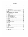
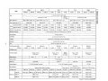
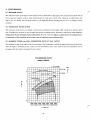
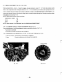
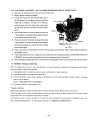
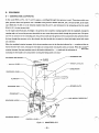
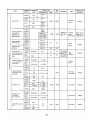
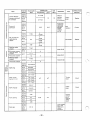
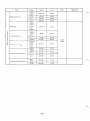
1
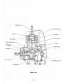
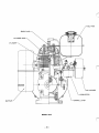
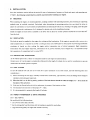
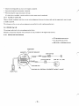
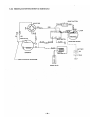
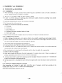
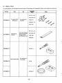
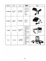
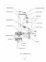
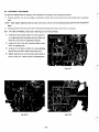
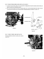
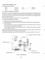
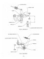
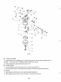
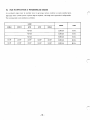
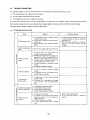
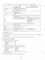
ROBIN AMERICA, INC.
ROBIN TO WISCONSIN ROBIN
ENGINE MODEL CROSS REFERENCE LIST
WISCONSIN ROBIN
ROBIN
0
SIDE VALVE
W 1-080
W1-145
W1-145V
W1-185
W1-185V
W1-230
W 1-280
W 1-340
W 1-390
Wl-45OV
EY21W
EY44W
EY18-3W
EY25W
EY27W
EY08
EY15
EY 15V
EY20
EY2OV
EY23
EY28
EY3 5
EY40 EY45V
EY2 1
EY44
EY 18-3
EY25
EY27
OVERHEAD VALVE
WO1-115
wo1-120
WO1-150
WO1-170
wo1-210
WOl-250
WO 1-300
WO1-300V
WO1-340
WO 1-340V
WO 1-43
OV
EH11
EH12
EH15
EH17
EH21
EH25
EH30
EH30V
EH34
EH34V
EH43V
0
TWO CYCLE
WT1-125V
EC13V
DIESEL
DY23
DY27
DY30
DY35
DY4 1
WRD 1-230
WRD 1-270
-1-300
WRD1-350
WRD1-410
0
CONTENTS
Title
Section
.
1 SPECIFICATIONS
2. PERFORMANCE
2.1
2.2
2.3
.
.
.
...........................................
1
............................................
2
Maximum
Output
.......................................
ContinuousRated Output . . . . . . . . . . . . . . . . . . . . . . . . . . . . . . . . . .
MaximumTorque andFuelConsumptionRatio
a t Max . Output . . . . . . . .
.
................................................
4 . GENERALDESCRIPTION of ENGINECONSTRUCTION . . . . . . . . . . . . . . . .
3 FEATURES
4.1 .
4.2 .
4.3 .
4.4 .
4.5 .
4.6 .
4.7 .
4.a .
4.9 .
4-10.
4-11.
4- 12.
4-13.
4.14 .
4-15.
.
.
2
2
2
5
6
SectionalView of Engine . . . . . . . . . . . . . . . . . . . . . . . . . . . . . . . . . .
6
Crankcase . . . . . . . . . . . . . . . . . . . . . . . . . . . . . . . . . . . . . . . . . . . . .
14
Baseplate . . . . . . . . . . . . . . . . . . . . . . . . . . . . . . . . . . . . . . . . . . . . . 14
CrankshaftandConnecting Rod Assy . . . . . . . . . . . . . . . . . . . . . . . . . . 14
14
Piston . . . . . . . . . . . . . . . . . . . . . . . . . . . . . . . . . . . . . . . . . . . . . . .
Driving Shaft (for Model B only) . . . . . . . . . . . . . . . . . . . . . . . . . . . . .
15
15
Cylinder . . . . . . . . . . . . . . . . . . . . . . . . . . . . . . . . . . . . . . . . . . . . . .
15
Cylinder Head (Model EC10.17.2 5.2 only) . . . . . . . . . . . . . . . . . . . . . .
Governor . . . . . . . . . . . . . . . . . . . . . . . . . . . . . . , . . . . . . . . . . . . . . . 15
Cool'ing . . . . . . . . . . . . . . . . . . . . . . . . . . . . . . . . . . . . . . . . . . . . . .
15
Ignition . . . . . . . . . . . . . . . . . . . . . . . . . . . . . . . . . . . . . . . . . . . . . . 15
Carburetor . . . . . . . . . . . . . . . . . . . . . . . . . . . . . . . . . . . . . . . . . . . .
16
Air Cleaner . . . . . . . . . . . . . . . . . . . . . . . . . . . . . . . . . . . . . . . . . . . .
16
ReductionEquipment (for Model B only) . . . . . . . . . . . . . . . . . . . . . . . 16
.............................
Starting Pulley or Recoil Starter
16
5 INSTALLATION . . . . . . . . . . . . . . . . . . . . . . . . . . . . . . . . . . . . . . . . . . . . .
5.1 .
5.2 .
5.3 .
5.4 .
5.5 .
5.6 .
Page
17
Mounting . . . . . . . . . . . . . . . . . . . . . . . . . . . . . . . . . . . . . . . . . . . . .
17
Ventilation . . . . . . . . . . . . . . . . . . . . . . . . . . . . . . . . . . . . . . . . . . . . 17
Exhaust Gas Evacuation . . . . . . . . . . . . . . . . . . . . . . . . . . . . . . . . . . .
17
Fuel System . . . . . . . . . . . . . . . . . . . . . . . . . . . . . . . . . . . . . . . . . . .
17
PowerTransmission to Drive Machines . . . . . . . . . . . . . . . . . . . . . . . . .
17
Wiring . . . . . . . . . . . . . . . . . . . . . . . . . . . . . . . . . . . . . . . . . . . . . . . 18
.
6 DISASSEMBLY and REASSEMBLY. . . . . . . . . . . . . . . . . . . . . . . . . . . . . . . . 20
6.1
6.2
6.3
.
.
.
PreparationsandSuggestions . . . . . . . . . . . . . . . . . . . . . . . . . . . . . . . . 20
Special Tools . . . . . . . . . . . . . . . . . . . . . . . . . . . . . . . . . . . . . . . . . .22
Disassembly and ReassemblyProcedure . . . . . . . . . . . . . . . . . . . . . . . .
24
7. MAGNETO
7.1 .
7.2 .
7.3 .
7.4.
................................................
29
Magneto. . . . . . . . . . . . . . . ; . . . . . . . . . . . . . . . . . . . . . . . . . . . . . .
Breaker PointAdjustment . . . . . . . . . . . . . . . . . . . . . . . . . . . . . . . . . .
TimingAdjustment . . . . . . . . . . . . . . . . . . . . . . . . . . . . . . . . . . . . . .
Magneto TroubleShooting . . . . . . . . . . . . . . . . . . . . . . . . . . . . . . . . .
29
29
30
...............................................
32
Construction and Operation . . . . . . . . . . . . . . . . . . . . . . . . . . . . . . . .
Governor
Adjustment
....................................
High Speed Adjustment . . . . . . . . . . . . . . . . . . . . . . . . . . . . . . . . . . .
32
34
36
8. GOVERNOR
8.1 .
8.2 .
8.3 .
9. CARBURETOR
9.1 .
9.2.
9.3.
31
.............................................
38
Construction and Operation . . . . . . . . . . . . . . . . . . . . . . . . . . . . . . . .
DisassemblyandReassembly
................................
Adjustments . . . . . . . . . . . . . . . . . . . . . . . . . . . . . . . . . . . . . . . . . . .
39
39
10. RUN-IN OPERATION of REASSEMBLED ENGINE
41
....................
42
I 1 . TROUBLESHOOTING . . . . . . . . . . . . . . . . . . . . . . . . . . . . . . . . . . . . . . . .
43
Starting Difficulties . . . . . . . . . . . . . . . . . . . . . . . . . . . . . . . . . . . . . .
Slow-Speed out of order . . . . . . . . . . . . . . . . . . . . . . . . . . . . . . . . . . .
Overheatingand Knocking . . . . . . . . . . . . . . . . . . . . . . . . . . . . . . . . .
Power Drop . . . . . . . . . . . . . . . . . . . . . . . . . . . . . . . . . . . . . . . . . . .
Excessive FuelConsumption . . . . . . . . . . . . . . . . . . . . . . . . . . . . . . . .
Engine Hunting . . . . . . . . . . . . . . . . . . . . . . . . . . . . . . . . . . . . . . . . .
OtherComplaints . . . . . . . . . . . . . . . . . . . . . . . . . . . . . . . . . . . . . . .
43
44
44
45
11.1 .
11.2.
11.3.
11.4.
1 1 .5.
11.6.
11.7 .
12. CHECKS and CORRECTIONS
13. MAINTENANCE and STORING
...................................
..................................
13.1 . Daily ChecksandMaintenance
..............................
13.2 . Every 50Hours (10Day) ChecksandMaintenance . . . . . . . . . . . . . . . . .
13.3 . Every 100-200 Hours (Monthly) ChecksandMaintenance
...........
13.4 . Every 500-600 Hours(Semiannual) ChecksandMaintenance
.........
13.5 . Every 1000 Hours (Yearly) ChecksandMaintenance
...............
13.6 . Preparation for LongAbeyance . . . . . . . . . . . . . . . . . . . . . . . . . . . . . .
45
45
45
46
53
53
53
53
53
54
54
0
. -
1. SPECIFICATIONS
1
T
a
P
c
a
-1-
f
5m
Lo
0
0
0
0
Lo
c
'4
.
0
0
ln
.
9
2. PERFORMANCE
2-1 MAXIMUM OUTPUT
The maximum output of an engine is such standard power as developed by that engine, after its initial run-in period with all
the movingparts
properlyworn-in,whenoperatingwith
engine may notdevelopthismaximum
the fully open throttle
valve. Therefore, it follows that a
output in the beginning,becausemovingpartsarenot
new
inaproperlyworn-in
condition.
2-2 CONTINUOUSRATEDOUTPUT
The continuous rated output
of an engine is such power as developed by
that engine when running
at an optimum speed
most favorable from the point of view of engine life and fuel consumption ratio. Therefore, it follows that when designing a
driving system for any mechanism, with a modelEC05-2,07-2,
IO, 17 or 25-2 engine, as a prime mover, the continuous power requirement of that mechanism must be kept below the continuous rated output
specified.
2-3 MAXIMUMTORQUE and FUELCONSUMPTIONRATIOATMAX.OUTPUT
The maximum torque of an engine is that driving torque of the driving shaft at which the engine is driving an external load,
while the engine is developing its max. output. The fuel consumption ratio at max. output is that fuel consumption ratio of
an engine while that engine is running at the max. output.
PERFORMANCE CURVE
MODEL EC05-2D
I
for B tvoe
0.4 (1.09)
0.3 (0.82)
HP
2500 3000 3500' 4000 4500 5000 5500
(910) (1090) (1270) (1460)(1640) (1820) (2000)
-2-
t
PERFORMANCE CURVE
MODEL EC07-2D
(
) for B type
HP
t
PERFORMANCE CURVE
MODEL ECIOD
(
)for B tj
4
3
HP
t
2
1
0
(1000)
(1200)
(1400)
(1600)
-
rpm
-3-
(1800) (2000)
PERFORMANCE CURVE
kg-m
HP
PERFORMANCE CURVE
MODEL EC25-2DS
kg-m
HP
t
-4
-
__c
rpm
3. FEATURES
COMPACT, LIGHT WEIGHT, HIGH PERFORMANCE and LOW FUEL CONSUMPTION.
TROUBLE FREE because of simpledesign and easy to handle.
5.
HIGH DURABILITY engine withstand long severe operation.
4.
TILTED OPERATION available.
As a special feature of 2-cycle engine, can operate at up to about 30' tilted position just before the
fuel flooding out
from the air-bent of carburetor.
5.
EASY STARTING
Recoil type starter is available at option.
6.
*-
LIGHTING for night operation.
Optional lighting is available by installing special lighting coil.
.
Lighting Capacity:
EC05-2,07-2 ( 1 2V
EC10,17(6
EC25-2
- 16V, 6W)
- 8V,15W)
.
(1'2V, 18
.
- 25W)
7. VERSATILE APPLICATION
Direct,or reduction type engine with horizontal shaft orvertical shaft are available.
Wide selection of driving shaft size and shapes are also available beside standard specification.
Further,consultwith
dealer for smallerfuel
tank,heavy-dutyfilterelementfor
air cleanerandhigh-performance
muffler.
8.
The engine can control to the desired speed with a ALL-SPEED GOVERNOR.
It can. be set for any desired speed by simply moving the controllever. The setting speed is maintained even under varying load.
9.
-
Engine withstand AGAINST HIGH VIBRATION environment.
4. GENERALDESCRIPTION
of ENGINECONSTRUCTION
4-1 SECTIONAL VIEW of ENGINE
FUEL TANK CAP
\
MUFFLER COVER 7
\ I
MUFFLER
GOVERNOR
CONTROL LEVER
MODEL EC05-2,07-2
-6-
FUEL TANK
PISTON PIN
BLOWER
HOUSING
FLYWHEEL
STARTING
PULLEY
NlTlON COIL
MODEL'EC05-2.07-2
I
.
FUEL TANK CAP
r
CYLINDER
MUFFLER COVER-
FUEL TANK
7
\\
CLEANER
ETOR
'ER
GOVERNOR ARM
MODEL ECIO
-8-
f
FUELTANK
CYLINDE
CYLINDER
\
:LEANER
MUFFLER
MODEL EC17
-10-
1
1,
MODEL EC17
- 11 -
0
0
0
0
0
0
0
0
0
0
0
0
0
0
0
0
0
0
0
0
0
0
0
0
0
0
0
0
0
0
MUFFLER-
MODEL EC25-2
- 12-
7
FUEL TANK
SPARK PLUG
CYLINDER H E A D 7
.BLOWER HOUSING
-COOLING FAN
. IGNITION COIL
.STARTING PULLEY
P. T
,FLYWHEEL
-CRANKSHAFT
MODEL EC25-2
-13-
4-2 CRANKCASE
All parts related with crankcase
assy are aluminium alloy diecastings, which removed all unnecessary
excess thickness for
extreme lightness, consist of split-type front crankcase, rear crankcase and crankcasecover (for Model D) or reduction cover
(for Model B) depending upon the model as per the following table,
Model
Front Crankcase
D
EC05-2
Crankcase Cover Rear Crankcase
Reduction Cover
for D type
B
Exclusive for B
Exclusive for B
~
D
EC07-2
-
EC10
Exclusive for D
for D type
B
D
B
Exclusive for B
Exclusive for D
for D type
Exclusive for B
Exclusive for D
Exclusive for B
~
Exclusive for D
D
Exclusive for D
B
EC17
I
v
for D type
v
EC25-2
D
for D type
DS
for DS type
Exclusive for B
Exclusive for D
Exclusive for D
Exclusive for V
~Exclusive for D
/
Exclusive for B
Exclusive for V
Exclusive for D.DS
Model EClOD, V. EC17D, V. EC25-2D. DS:
The rear crankcase forms a governor chamber and provided with crankcase cover.As front, rear crankcase cover hasone ball bearing respectively, the crankshaft is supported by 3 ball bearings.
Model EClOB, EC17B
The rear crankcase forms a part of the reduction gear chamber and after installing the reduction gear and governor, reduction cover is to be
fitted. The reduction cover has two ball bearings, one is supporting the crankshaft and the other one is supporting the driving shaft.
4-3 BASE PLATE
of aluminumalloydiecasting
Thebaseplatemade
is to beattached
to thefrontandrearcrankcase.with
4 bolts.
4-4 CRANKSHAFT and CONNECTINGROD ASSY.
Thecrankshaft
is separable intothefrontcrankshaft,rearcrankshaftandcrankpin.
Crankshaft
is
made
of forged
carbon
steel;
Crank
pin
is made of chromium-molybdenum
steel,
hardened
and
precision machined.
Connectingrod
is aforged
small ends.Bothrodends
Thefront,
chromium-molybdenumpiecewhich
hasan
is equippedwith
needle-bearings at both large and
oilgrooves to deliver lubricant t o preventburningandwearing.
rear crankshafts and the crankpinareassembledtogetherandforcefittedinexactalignmentwiththe
specialassemblingfixtureafterfittedtheneedle-bearingandconnectingrod
notdisassembled.In
case of replacing thecrankshaft,it
onthe
crankpin.Generally,
they can
is requested to replacecrankshaftandconnectingrodin
assembled manner.
4-5 PISTON
The piston is made of precision-casted heat-resistant aluminum alloy which machined precisely into oval section in order t o
prevent from burning and slapping. It is attached to the connecting rod small end by means of a piston and a needle bearing.
Near the top of the piston, there are two grooves for compressionrings. In order to prevent the rotating the rings during the
operation and damaging the cylinder port, lock-pins are inserted.
- 14-
4-6 DRIVING SHAFT (P.T.O. shaft) (for Model B only)
The driving shaft is made of forged carbon steel and reduction gear i s force-fitted.
4-7 CYLINDER
‘Model EC05-2, EC07-2
Monoblockcylinderandcylinderhead
.is made of aluminum alloy diecastingand-insidethecylinder
is treatedwith
hard-chromium plating to withstand against the wear by reciprocal motion of the piston.
Outside fins of cylinder-head are arranged to get efficient heat dispersion and provided with threaded hole for mounting a
spark plug on the top.
Inside the cylinder, one each of intake port, exhaust port
and two scavenging ports are positioned to
get the maximum
engine performance.
-.
Model ECIO, EC17
The cylinder is made of precision-casted wear-resistant cast iron provided with fins for perfect heat dispersion.
Inside the cylinder, one each
of intake port, exhaust port and two
scavenging ports are positioned
to get the maximum
engine performance.
The cylinder is attached to the crankcase with the flange, which positioned lower part of cylinder, by stud-bolts.
*Model EC25-2
The cylinder with the cylinder liner is made of aluminium alloy. The cylinder liner is made of special cast iron and are imbedded in the aluminium casting as inserts. Inside the cylinder, one each of intake port, exhaust port and four scavenging
ports are positionedto the maximum engine performance.
4-8 CYLINDER HEAD (Model ECIO, 17,25-2 only)
The cylinder head
is made of heat-conductive aluminum alloy and
is provided with the fins, arranged in the direction
of
cooling air to achieve the efficient cooling.
The combusion chamber forms semi- spherical and
is provided with threaded hole for mounting a spark-plug on the top.
4-9 GOVERNOR
The centrifugal flyweight type governor assures constantspeed operation at selected speed, irrespective of load fluctuations.
(The governor is built-in the crankcase for Model EC05-2,07-2) As to the detail, refer to section“8. GOVERNOR”.
4-10
COOLING
The cooling fan which also serves as a flywheel forcily feeds cooling air to the cylinder and cylinder head with
the aid of
blower housing and air buffle.
4-11 IGNITION
The ignition system is of flywheel magneto type with ignition timing set at23” before TDC for EC05-2, 07-2, 25-2, 18” before TDC for EC10 and22” before TDC for EC 17 respectively.
The flywheel with steel magnet piecerevolves outside the coil and generates the electric powerin the coil. The flywheel also
equalize the engine revolution and at the same time,
it serves as a blower, with its impellerson thecircumstance, for cooling
the engine. The igntition coil andt h e breaker are mountedin the crankcase.
As to the detail, refer to “Section 7 . MAGNETO”.
-15-
4-12 CARBURETOR
A horizontal draft float type carburetor
is employed. Its setting has been carefuily determined after thorough testing
to
achieve best starting, accelerating, fuel consumption, output and performances.
As to the detail suchas construction, refer to section “9. CARBURETOR”.
4-13 AIRCLEANER
Air cleanerused
inthismodel
dustparticlesfloating
is asemi-wet
in the intake
4-14 REDUCTIONEQUIPMENT
type cleaner,whichcontainsoilsoakedfilteringelement
air so that cleanair
thattraps
all
is supplied to the carburetor.
(For Model B only)
With the Model B engine, rear crankcase and reduction cover forms the reduction chamber, and the revolution
of crankshaft
reduced t o 1/2.7 for Model EC05-2, 07-2, to 1/25 for Model EClO and EC17 by reduction-gear and pinion, and then its
transmitted t o P.T.O.shaft. Governer is also equipped with reduction chamber and lubricated by same lubricant.
Use SAE 30 lubricant. (for EClO, 17)
4-15 STARTINGPULLEY or RECOILSTARTER
Optional recoil starter is available for Model D and B.
Model V is equipped with recoil starter.
Starting pulley of Model D and B are identified according to the direction of engine rotation.
By removing the recoil starter, starting theengine can be made by starting pulley.
- 16-
- 5. INSTALLATION
Since the installation method affects the service life, easy of maintenance, frequency of check and repair, and operating cost
of engine, the following contentsshall be carefully examined before installing
your engine.
5-1 MOUNTING
When installing the engine, its mounting position, coupling condition with operating machines, and anchoring or supporting
m&o&
must be carefully
examined. Particularly when determining its mounting position, due care should
be taken to
assure the convenience of such routines as replenishment and checking of fuel and oil, checking of oil gauge, spark-plug and
contact breaker point, maintenance of oil draining. For details, refer to the installation drawing.
Install the engine as much closer as possible to the level. The tilt limit for normal operation should be not more than
30°
from the level.
5-2 VENT1 LATION
The fresh air must be supplied to the engine for cooling and fuel combustion. If the engine i s operated with a cover o r in a
small compartment,' it is required to provide a cooling air duct and a baffle plate.for the purpose of preventing insufficient
circulation of heatedairaftercooling
the engine and/ortemperature
rise of relatedequipment.
High temperature
environment will cause engine vapor-lock, deterioration of oil, power reduction, loss of engine life, it is requested to keep
the temperature of compartment not to exceed 50°C.
5-3 EXHAUST GAS EVACUATION
As the exhaust gas is toxic, it must be exhausted outside in case engine is operated indoor.
Output power of 2-cycle engine is considerably influenced by the length of exhaust duct, so ask for consultation in case any
modification of exhaust system is required.
5 4 FUEL SYSTEM
In case the standard fuel tank can not
be used d u e t o space limitation or any other reason, take the following notes into
consideration:1) When connecting the fuel pipe, carefully examine heat conductivity, pipe diameter, bend and
leakage from fittings to
eliminate air-blocking and vapor-lock.
2) M e n the fuel is to be fed by gravity, position of fuel tank bottom should fie within the height of 5
fuel joint of the carburetor.
.
3)
Fuel must be filtered before it is fed to carburetor, by means of fuel strainer or filter.
4)
The standard inner diameter of fuel pipe is 4
- 5 mm.
5 ) It is recommended t o minimize the length of fuel pipe.
5-5 POWER TRANSMISSION to DRIVE MACHINES
5-5-1 BELT-DRIVE
Be careful with the following items.
Use a V-belt rather t h a n a flat-belt.
Set the driving shaft and the driven shaft of machine in parallel for each other.
Align the driving pulleys o f engine and machine correctly.
- 17 -
- 50 cm from the
*
*
*
Mount the driving pulley as close to the engine as possible.
Span the driving belt horizontally, if possible.
p"
When starting the engine, disconnect the load.
If a clutch is not available, a tension pulley or other means must be employed.
5-5-2 FLEXIBLE COUPLING
When a flexible coupling is used, the run out and mis-alignment between the driven shaft and the engine shaft must be made
as small as possible.
The tolerance on the runout and mis-alignment are specified by each coupling manufacturer.
"c3JIS CB104 female terminal
JIS CA104 male terminal
4 LA104 or LA108 plate terminal
CONDENSER
r'
\ '
ONTACTBREAKER
STOP BUTTON
LIGHTINGSWITCHLAMP
"
"
"
IGNITION COIL
SPARK PLUG
- 18-
(6V
-
8V. 15W)
5-6-2 ENGINE with STARTING MOTOR (for EC25-2DS only)
START BWTTON
1
+- I
I
R ECTl F I ER
YELLOW^
I
PINK
I -
I
I
I
MAGNETO
LIGHT BLUE WITH BLACK TUBE
SPARK PLUG
- 19-
BATTERY
6. DISASSEMBLY and REASSEMBLY
6-1 PREPARATIONS and SUGGESTIONS
6-1-1 DISASSEMBLY
When disassembling the engine, memorize where and how each part is assembled
in order to be able to reassemble it
correctly. Tag parts if there is a possibility of confusion.
Take care not t o damagepackingsandgaskets,whicharefragile.
Inorderto
prevent missing and misplacing, grouprelatedpartstogether,tentativelyassemblingthem,immedi-
ately after disassembled each sub-assemb!y.
Handle the disassembled parts carefully, and wash them in Kerosene.
Use the correct tools in the correct way.
Standard tools required for disassembly and reassembly.
a> Work table
b)
Washing pan
c)Disassembling
tools
d)
Washing oil (Kerosene or gasoline), Mobile oil, Brush
e)
Emerypaper,Cloth
Before starting to disassemble the engine, drain fuel and lubricant. (To prevent from danger and stain.)
6-1-2 CLEANING before reassembly
1 ) Check all sliding and rotating parts, such as piston, cylinder,
valve, camshaft, crankshaft, gears and bearings for defect.
2) Wash the disassembled parts in Kerosene t o remove dust, dirt and contaminated oil thoroughly. Wash them twice, first
r"
time remove visible dirt roughly, and second time using fresh Kerosene.
3) After washing, blow them thoroughly with compressed air.
4) Do not wash electric parts. Wipe them with clean cloth and dry them.
5) Accumulated carbon on the cylinder-head, gasket, piston, cylinder and inside the muffler to be carefully planed and
wrap the piston withoil stone to get smooth surface.
6 ) Parts of carburetor to be washed carefully with gasoline and blow them thoroughly with compressed air.
7 ) Check the cable for any damage.
8) Clean contact breaker with dry cloth. Check the breaker-point
if it contact surface is flat.
If there is a n evidence of
pitting or pyramidding, this should be corrected with M O O wrapping paper.
9) Air-cleaner element shall be soakedin the liquid soap and drythoroughly.Then putit to mixture of 2
- 4 kerosene and
1 engine oil, and assemble it after squeezed well.
10) Take special care not to contaminate the parts with dust and apply mobile oil
on the surface in order t o prevent from
rust.
6-1-3 CHECKS and CORRECTIONS before reassembly
Afterdisassembingandcleaning
the engineparts,checkthemand,
CORRECTION TABLE of section '' 12.CHECKS and CORRECTIONS".
Gaskets and fuel pipe shall be replacedto new one.
- 20 -
if necessary,correct
themaccordingtothe
'
6-1-4 REASSEMBLY
1)
Before reassembly, wash parts in gasoline.and blow
2)
Apply mobile oil on the rotating andsliding surface.
them with compressed'air.
3) Take care not t o contaminate the parts with dust duringreassembly.
4)
Be sure t o assemble those parts provided with alignment marks by bringing the marks in alignment.
5)
Tighten'bolts, nuts and' screws to the correct torque
specified. When there
is no torque specification, tighten them
to torque readings appropriate t o t h esize
Standard Fastening Torque for screws are as fallows:
. .
6mm8mm10 mm
.
90 kg-cm (6.5 ft-lbs)
250 k g c m (18 ft-lbs)
- 370 kg-cm (26.7 ft-lbs)
If.small screwsaretightened
t o o hard,theymaygetbroken.Tightenthelargesizescrewssuchasonesforthe
magneto flywheel, enough by giving hammer blows on the socket wrench handle.
When tightening the several screws fastening the single part, tighten them all evenly, by alternately tightening diagonally
located pairs.
6 ) Do not apply oil to the part to which packings or sealend to be fitted.
7) When engine is completely reassembled, make sure that there is no parts remained.
8) During the assembly, turn the moving part by hand
t o check for friction and noise.
9 ) After the completion of reassembly, turn the engine by hand and checkif there is any disorder or loose members.
- 21 -
5-2
SPECIAL
TOOLS
For your reference, the following'showsspecial tools of Robin Engine for Disassembly, Meauring and Inspection instruments.
Part No.
Tool
USe
Applicable
Model
f-
Shape
EY10,13,14
EYl8,25,27
2099500407
Flywheel Puller
(with bolt)
For pulling off
Flywheel
EY33,44
EC05,07,10
EC 17,37
EY10,13,14
207 95003.07
Valve Spring
Retainer
For mounting and
dismounting Valvc
Spring Retainer
and Retainer Lock
EY18,25,27
EY21,80
EY33,44
f
\
20595001 07
EY13,14
rlalve Guide Puller
For pulling off
Valve guide
2069500107
EY18
2079500107
EY25,27
- 22 -
~~
Part No.
-
Tool'
Uu,
Applicable
Model
EY10,13,14
EY18,25,27
214 91301 00
C. D. 1. Unit
Checker
For checking
C. D. 1. Unit
EY33,44,21
EY80
EC03,04
1067990100
T. C. 1. Unit
Checker
For checking
T.C. 1. Unit
EC05,07
EC10,17
EYlO, 13,14
EY
"20248
Timing Tester
.For adjusting
Timing
18,25,27
EY33,44,21
EY80
EC03,04,05
EC07,10,17
EC37
EY10,13,14
EY 18,25,27
EY33,44,21
PF-2L
Coil Tester
For checking
Ignition Coil
EY80
EC03,04,05
EC07,10,17
EC37
-23
-
6-3 DISASSEMBLY and REASSEMBLYPROCEDURE
6-3-3 FUELTANK
and FUELTANKBRACKET
’
1)
Disconnect fuel pipe between strainer and carburetor at carburetor side.
2)
Remove mounting bolts, and detach fuel tank from cylinder head or cylinder.
3)
For Model ECl OV
\
’
Unscrew 6 x M8 bolts, then remove fuel tank from blowerhousing.
CAUTION: REPLACE FUEL PIPE ONCEA
YEAR IN ORDER TO PREVENT FROM THE OCCURANCE OF
DANGER CAUSED BY THE FUEL LEAKAGE.
6-3-2AIRCLEANER
“Model EC05-2D & 6,07-2D &
B, 10D & B, 17D & B, 25-2D & DS
Remove air cleaner cover and element.
1)
2) Unscrew two or three bolts which clamped air cleaner base plate to carburetor and remove base plate.
Model ECIOV
1) Remove
2)
cover and take out outer element and inner element.
Loosen three bolts which clamped base plate to carburetor, and remove base plate.
In reassembly:
Wash elementbased
on followingprocedurebeforereassembly;
‘Model EC05-2D &B, 07-2D & 6, 1 OD & 6,170 & B, and 25-2D & DS
After washed element with gasoline, soak
it into the mixed oil of 2
- 4 kerosene and 1 engine oil,then reassemble it after
drip the oil off.
” Model EClOV
After washed outer and inner elements with gasoline, soak them into the mixedoil of 2
- 4 kerosene and 1 engine oil.
6-3-3
CARBURETOR
1)
Remove governor rod and rod spring from carburetor..
2)
Remove carburetor from cylinder block.
In reassembly:
Refer t o section “8. GOVERNOR” and section “9. CARBURETOR”.
6-3-4
GOVERNOR
LEVER
1)
Remove governor lever from governor shaft.
2)
Remove governor spring from control lever.
3)
Control lever and stop plate can be removed by loosing wing-nut or bolt but do not disassemble unless it necessary.
NOTE: When control lever device are disassembled, tentatively assemble them together with governor lever.
In reassembly:
Refer t o section “8. GOVERNOR”. Assembly shall be made securely including rotation adjustment.
6-3-5 MUFFLER
Unscrew nuts and remove it from cylinder.
6-3-6BLOWER
1)
HOUSING
Disconnect stop button wires from Connector.
2) Unscrew bolts and remove blower housing from crankcase.
- 24 -
f
\
6-3-7 RECOIL STARTER
Standard configuration on Model EClOV, 17V.
Optional equipment for other models.
M6 bolts (4
1)
Remove recoil starter from blower housingb y unscrew 3
2)
Remove starting pulley from flywheel by loosing bolts clamped.
X
X
M6 bolts for Model EC17)
NOTE: Unless it is necessary, do not disassemble recoil starter as special tools are required for reassembly.
6-3-8STARTING PULLEY and MAGNETO (Fig. 6-3-1)
Remove’ starting pulley from flywheel.
Remove flywheel from crankshaft.
Apply
socket
a
wrench
over
crankshaftand
thenut
at
end
of
a
give the wrench a sharp blow with
soft. hammer.
Remove
nut
and
spring
washer.
Attach
flywheel
puller t o flywheelasillustratedin
Fig.6-3-1,
turn
centerboltclockwiseuntilflywheel-becomesloose
enough to be removed.
high tension cable of
Removesparkplugcapfrom
igniton coil and remove ignition coil from crankcase.
Fig. 6-3-1
Take off the point cover and remove contact breaker
and” condenser, fromcrankcase.
In reassembly:
Refer t o “7-2 BREAKER POINT ADJUSTMENT”, “7-3 TIMING ADJUSTMENT” sections.
6-3-9 CYLINDER HEAD (Model EC10, 17 only)
1)
Remove spark plug from cylinder head.
2) Unscrew mounting special bolts and remove cylinder head from cylinder.
3)
Remove cylinder headgasket from cylinder.
In reassembly :
1)
Clean carbon from combustion chamber and dirt from between the cooling fins of cylinder head.
Check its mounting face for distortion.
2)
Use new -cylinder head gasket.
NOTE: Cylinder head gasket must be placed folded edge upside (To the cylinder head).
3)
Cylinder head fin must be placed in paralle with crankshaft.
Fastening torque of cylinder head is as shown below:
-180
EC17 -370
EClO
EC25-24)
200
-
- 16 ft-lbs)
420 kg-cm (26 - 30 ft-lbs)
220 kg-cm (13
250 kg-cm (15
-.
18 ft-lbs)
Fastening torque of spark-plug is as shown below:
250
300 kg-cm (18
-
22 ft-lbs)
L
.
.
I
- 25 -
,
6-3-10CYLINDER
1)
Remove cylinder from crankcase by removing nut and spring washer.
NOTE: For
Model EC05:2,07-2
Remove spark plug prior to removing cylinder.
2)
Removecylindergasket.
3)
For Model EClOV remove intake pipe from cylinder.
In reassembly:
1) Clean carbon deposit from cylinder
head and combustion chamber.
CAUTION:WITHOUTCLEANINGTHECARBON
DEPOSIT, ITMAYDAMAGETHE
PISTON ANDINNER
SURFACE OF CYLINDER WHEN REASSEMBLY.
Replace cylinder gasket to new one.
Intake of cylinder should be positioned to the left against view from blower side, Apply oil to piston ring and cylinder
walls, then after assembled the cylinder securely, make sure
if t h e crankshaft rotate smoothly.
Fastening
torque
of cylinder is as shown
below:
Fastening
torque
kg-cm
90-100
EC05-2
( 6 . 250-300
5 9E05-2
ft-lbs)
kg-cm
90-100
EC07-2
(6.5-7
ft-lbs)
(18-22
250-300
kg-cm
E07-2
ft-lbs)
EClO
of spark
plug
for
EC05-2,
07-2:
kg-cmft-lbs)
(18-22
90-100 k g c m (6.5-7 ft-lbs)
EC17
180-220
kg-cm
(13-1
EC25-2
340-400 k g c m (25-29
ft-lbs)
6 ft-lbs)
CAUTIONS:
r)
WHEN FASTENING CYLINDER, TIGHTEN FOUR NUTS UNIFORMLY.
2) BEFORE
REASSEMBLE
CYLINDER, APPLY
OIL
ON
NEEDLE
BEARING
LOCATED
TO
END
OF
CONNECTING ROD.
6-3-1
1 PISTON
1) Remove both
2)
side piston pin clips
Pull out piston pin and disconnect the needle bearing from small end
CAUTION:
I N ORDER NOT TO DAMAGE
of connecting rod.
PISTON, PULL OUT PISTON PIN BY FIRMLY HOLD PISTON. ALSO
TAKE A SPECIAL CAUTION WHEN DISASSEMBLE NEEDLE BEARING.
3)
Remove piston rings from piston by expanding the open endsof rings.
In'reassembly :
PISTON RINGS (Fig. 6-3-2,
6-3-3)
If an expanding toolis not available, install rings by placing the open end of the ring on first land of piston, spread ring only
far enough to slip over the piston and carry it into correct groove,
CAUTIONS:
1)
BE EXTREMELY CAREFUL NOT TO DISTORT AND BRAKE THE RING.
2) STRIKETHEKNOCKPIN
TO THEGROOVELOCATEDON
OPEN ENDOFRINGS(THIS
IS TO
PREVENT FROM THE ROTATION OF RINGS WHILE OPERATING THE ENGINE.)
31 ASSEMBLE RINGS IN THE ORDER OF 2ND RING AND IST RING.
(Fig. 6-3-3)
1ST RING -CHROMIUM PLATED SURFACE
2ND RING-
PERKARIZED SURFACE (2ND RING FOR MODEL
EC25-2
IS CHROMIUM PLATED SUR-
FACE.)
(RING FOR MODELS EC05-2,07-2IS NOT CHROMIUM PLATED.)
- 26 -
TOP RING
SECOND RING
..........
ISTON RING
Fig. 6-3-2
Fig. 6-3-3
PISTON
“F” mark of piston to blower side and reassemble
1) Position the
the piston and connecting rod
by firmly striking the
piston pin, and needle bearing.
OIL TO THE NEEDLE BEARING BEFORE
CAUTION: APPLY
2)
Assemblepistonpinclip.
CAUTION:
3)
REASSEMBLE I T TO PISTON-PIN.
REPLACE PISTON PIN CLIP I F THERE IS ANY LOOSENESS AFTER REASSEMBLE IT.
Be sure that piston and connecting rod moves smoothly after reassembled.
6-3-12 CRANKCASE COVER (Model D and V only)
( Fig. 6-3-4)
1)Discharge
oil by opening oil drain plug.
(No discharg-
ing the oil is required for Model EC05-2 and 07-2)
2)
Remove bolt and washer
3)
Removebolts
4)
Detach cover gasket.
from crankshaft end.
o n crankcase.
In reassembly:
1) Replace
cover gasket t o new one.
2) Check bail bearing and
oil seal if there is any damage.
And replace it if necessary.
3) Applyoil
o n bearingandoilseal,andcoat
contact
surface
guide
the to
oil-seal
Fig. 6-34
of crankcase
cover.
Attach oil seal guide on end of crankshaft and mount crankshaft
in crankcase with extra care not to damage
of oil seal. Then fasten the bolts uniformly.
Fastening torque is:
EClO
180
EC17
180
EC25-2
200
-
220 kg-cm (13
- 16 ft-lbs)
- 220 kg-cm (13 - 16 ft-lbs)
- 250 kg-cm (1 5 - 18 ft-lbs)
6-3-13 GOVERNER PLATE (Model D and V)
1) Pull out governer plate, governer sleeve, washer and clip
D
2)
from crankshaft.
Removewoodruffkey
In reassembly: Reassembly with reverse sequence correctly.
- 27 -
lips
6-3-14REDUCTIONCOVER
(Model B)
1)
Discharge oil by opening oil drain plug.
2)
Remove reduction cover by loosen the bolts on crankcase.
3)
Remove washer and bolt on driving shaft end.
4)
PUn out driving shaft with reduction gear from reduction cover.
f
“.
5) Opentaboflock-washerandpulloutpinion,governerplatp,governersleeve,washerandclipfromcrankshaft,and
detach 2 woodruff keys.
In reassembly:
Reassemble with reverse sequences. After tighten the nut, bend the tabof lock-washer without fail.
6-3-15GOVERNORSHAFT
1)
Unscrew 2 screws and remove governor arm.
2)
Pull out governor shaft with governor lever from’crankcase.
NOTE: Do not disassemble if not necessary.
t o section “8. GOVERNOR”.
In reassembly: Refer
6-3-16CONTROL
LEVER
Unless it is required, do not remove control lever from crankcase.
In disassembly and reassembly, refer t o section “8. GOVERNOR”.
6-3-17 BASE PLATE
Base plate can be removed by loosening4 bolts on crankcase.
In reassembly:
After reassembled base-plate to the crankcase, be sure that crankshaft
moves smoothly by holding small end of connecting
rod.
i
\
6-3-18 C RAN KCASE
Unscrew 4 bolts which fastening front crankcase and rear crankcase and separate
both crankcase by tapping them with soft
hammer, and detach crankshaft connecting rod assy.
In reassembly:
Before reassemble the front and rear crankcase, check bearings and oil seals if there is any damage and replace them in
case any damage found.
Apply oil onto the bearings of both crankcase and ascertain there is no warp on the lip of oil seal.
Clean the joint of both crankcases and apply seal end. Assemble the crankshaft and joint both crankcases with press (or
tap them with soft hammer) having extra care not to damage the oil seal.
Fasteningtorqueis:-
EC05-2
-90-100
kg-cm (6.5-7.0
ft-lbs)
EC07-2 -90-100 kg-cm (6.5-7.0 ft-lbs)
EClO -90-100 kg-cm (6.5-7.0 ft-lbs)
EC17
-90-100 kg-cm (6.5-7.0 ft-lbs)
EC25-2 -200-250
CATUION:
kg-cm (1 5-1 8 ft-lbs)
WHEN TIGHTEN THE SEVERAL BOLTS FASTENING CRANKCASE, ,TIGHTEN THEM A L L EVENL y
BY TIGHTENING DIAGONALLY LOCATED PAIRS AT SUGGESTED FASTENING TORQUE.
NOTE: After reassemble the crankshaft to the crankcase, be sure that crankshaft moves smoothly.
6-3-19CRANKSHAFT
and CONNECTINGROD ASSY.
Reassembly of crankshaft requires special tools.
Sub-assembly of crankshaft and connecting rod assembly is available as a spare parts.
- 28 -
. .
.
,
7 . MAGNETO
.
7-1 ' MAGNETO
._
.
The spark for ignition
'
".
.'
,
r
is furnished by a magneto assembly. The magneto consists of a flywheel, ignition coil and breaker
assembly.(.includingcondenser),
o f whichflywheel
is 'mountedon.crankshaftandignitioncoilandbreakerassemblyare
. - in crankcase directly.
mounted
7-2 BREAKER POINT ADJUSTMENT (Fig. 7-2)
The breaker points, which are mountedin the crankcase inside the flywheel should be checked twice a seasonor whenever the ignition, spark becomes weak.
If there is,evidence
of pitting or pyramidding, the breaker points must be corrected, and then it becomes necessary to readjust the
gap t o
its proper clearance. (0.4 mm for Model EC10)
The normal breaker point opening is 0.4 mm at full separation. Since the spark timing of 18" is regulated by the point
to obtain an accurate spark ad-
opening, use a timihg light
vance. (Refer t o "7-3TIMING ADJUSTMENT.")
NOTEI The point gap of other engines.than modelEC70 is
as follows:
I
.
EC05
:0.35 mm
EC07-2
:0.35mm'
ECl7
:0.30mm
EC25-2
:0.35mm
Ftg. 7-2
1
-
To adjust breaker poixit opening, remove starting pulley, blowerhoushg andflywheel from theeingine and proceed as follows:
i'
(See Fig. 7-2.)
',
.
Remove breaker cover from contact breaker.
1)
2) Turn crankshaft .over until. breaker arm comes in contact with. the high point
of the breaker cam. (maximum point
opening of 0.4 mm)
3)
Loosen contact suppoit plate lock screw just enough so that bracket can be moved.
4)
Insert a 0.4 mm feeler gauge between the points.
CAUTION: ADJUS? BREAKER POINT
,
GAP WITHOUT OPENING IT MORE THAN 2 mm, OTHERWISE RATED
-
HEEL-PRESSING FORCE MAY NOT BE: OBTAINED 'DUE TO THE BENDING Of CONTACT BREAKER ARM.
5)
Apply a screw driver to.adjusting tab and move the contact support plate just enough
so that a slight drag is felt while
sliding the feelergauge from between the points.
recheck
6 )andk gscrew
h t e n lock
Pull a strip of 8
7)
.
I
gap. point
breaker
.
.
- 10 mm wide white paper through the closed points to remove oil and dust on the point surfaces.
CAUTION: WHEN INSERTING A SHEET OF PAPER;,NEVER OPEN THE BREAKER POINTGAP MORE THAN:2mm.'
'.
8) Mount flywheel, blower housing and starting pulley
-. .
.
~
....
.
, .
.
.
V
I
.
on engine after adjustment.
.
. .
_..
With the Model EC05-2,07:2, 10, 17 and 25-2 engines, the spark is timed t o occur 18"
TDC on the compression stroke. This spark advance of 18"
- 23" is controlled
- 23" before the position reaches
by the breaker point opening and this ad-
vance is obtained when the breaker point openingis adjusted according to theBREAKER POINT ADJUSTMENT to its
proper point opening. However, the advance timing is more accurately adjusted through the following proceduresusing a
timing light as shown in Fig. 7-3-3.
NOTE: Spark advance of each model is as follows:
EC05, EC07-2, EC25-2
23"
EClO
:1 8
EC17
.-22"
NOTE: Refer to section "4-1I IGNITION. "and "12. CHECKSand CORRECTIONS."
7-3-1 ALIGNMENT MARK for TIMING ADJUSTMENT (See Fig. 7-3-1.)
For timing adjustment, the following alignment marks are provided shown
as
on Fig. 7-3-1.
*Line mark on crankcase
*Line mark on flywheel circumference and cooling fan
7-3-2 DEFERENCE among MAGNETO for D TYPE, V TYPE and B TYPE (See Fig. 7-3-2.)
D type and V type: Clockwise arrow is embossed on cooling fan.
B type:
Counter-clockwise
arrow
is embossed on cooling
fan.
TIMING M A R K S
Fig. 7-3-2
Fig. 7-37
- 30 -
7-3-3 FOR TIMING ADJUSTMENT, THE FOLLOWING PROCEDURES USING A TIMING,TESTER:
Disconnect the stop buttonlead wires and the coil primary wire.
Remove blower housing from engine.
Connect the timing tester lead with red rubber cap t o
the coil primary wire and ground the lead with black
rubber cap
t o crankcase. (See Fig. 7-3-3.) While the
points are open, the buzzer within tester remains
ringing and when the points are closed, the tester remains
silent.
TIMI
Turn flywheel slowly counter-clockwise (D type and
V type engines) or clockwise (B type engines) until the
buzzer within tester becomes silent.
Then, turn flywheel very slowly clockwise
(D type and
V type engines) or counter-clockwise (B type engines)
\
GROUND WIRE
and stop immediately the moment the buzzer within
begins
Fig. 7-3-3
tester
Check if line mark on the flywheel is in the line with line mark on the crankcase.
When the line marks are in alignment,
the timingis correct.
in alignment, then readjust the point opening according
to theBREAKER POINT ADIf the timing mark lines are not
JUSTMENT, by-removing the flywheel and repeat the checking procedures
3) through S).
Afer completing the timing adjustment re-mount the blower housing and connect the coiltoprimary
the stop
leadbutton.
MAGNETO’ TROUBLE SHOOTING
When the engine does not start or starts with difficulty, or when its operation is unstable, the following tests
will clarify if
they are caused by a defect in the magneto.
1) Check ignition cable for possible corrosion, broken, worn insulator or loose connection.
2) Check the sparking as described later in this section.
3)
Check if the breaker points require cleaning, or adjusting or not. If the points are badly corroded or pitted. Condenser
may have to be replaced.
Refer t o “BREAKER P0IN.T ADJUSTMENT”
4)
If no spark takes place, replace ignition coil.
SPARK TESTING
Remove spark plug from cylinder head and place it on blower housing, with the ignition cable connectedto it.
Crank the’ engine several times by starting pulley and observe the spark in the spark gap of spark plug. If the spark is strong,
the ignition system can be eliminated asthe source of trouble.
If the spark is weak or there
is no spark at all, repeat the checks according
The correct electrode gap is 0.5
-
to the procedures 1) through 3) above. The
0.7 mm.‘ (Refer t o section 12. CHECKS and CORRECTION.”)
-31
-
8. GOVERNOR
8-1 CONSTRUCTION and OPERATION
In the model EC05-2, 07-2, 10, 17 and 25-2 engines, a centrifugal flyweight type governor is used. The governor plate complete, governor sleeve and governor arm are installed in the governor chamber (EClOD, lev, 17D and 25-2D), in the crankcase (EC05-2D, 07-2D)
or in the reduction chamber (type B and V), and lubricated by the lubricating oil (in the model
EC05-2, 07-2, by the mixture fuel).
As the engine speed fluctuates, flyweight on thegovernor plate complete, rotating together with the crankshaft, changes its
opening angle and moves the governorsleeve, which in turn rotates the governor shaft through the governor arm. goverThe
nor lever is connected to the extending
part of the governor shaft and this governor
lever is connected to thecarburetor throttle lever through the governor rod at the other end; thus the throttle
valve is opened or closed and engine speed and output
are controled.
When the crankshaft rotation increases, all the relevant members move
in the direction indicatedby-marks
and the car-
buretor throttle valve closes, reducing the fuel supply and consequently reducing the speed and output.
When the crankshaft
rotation decreases, the same members
moie in the direction indicated by-- --marks and the carburetor throttlevalve open,
increasing the fuel supply and consequently recovering the failing speed and output.
GOVERNOR ROD SPRING
GOVERNOR ROD
THROTTLE VALVE
THROTTLE LEVER
CARBURETOR
GOVERNORLEVER
FLYWEIGHT
STOPPER PLATE
GOVERNOR ARM
CRANKSHAFT
HIGH SPEED STOPPER BOLT
GOVERNOR SLEEVE
GOVERNOR SPRING
CONTROL LEVER-
Fig. 8-1- 1
Model ECO5-2, 07-2
- 32 -
I
.
.., \-SPACER
\“SET
. .
PIN
GOVERNOR SLEEVE
..
..
Fig. 8-1-2 Model ECIO, 17,25-2
-33-
’
8-2 GOVERNOR ADJUSTMENT
The governor linkage should be adjusted, after reassemble it accordingto thefollowing procedures.
1)
Connect governor rod and rod spring
to carburetor throttle leverandgovernorlever,
then install these
t o governor
shaft.
NOTE: Never tighten adjusting plate set screw at this time, and do not fixed adjusting plate, governor lever and governor
shaft
2) Connect governor lever and control lever with governor spring, and install control lever o n crankcase.
8-2-1 IN CASE OF MODELS EC10, EC17 (See Figs. 8-2-1,8-2-2 and 8-2-3.)
As shown by arrow markon Fig. 8-2-1 turn controllever t o high speed side (clockwise) until stop fully, and
fasten the controllever by tightening wing bolt.
Loosen lock nut at the end of governor shaft and set
screw on adjusting plate.
As shown by the arrow on F i g . 8-2-2, move adjusting
plate all the way until it will not travel any more.
Tighten both lock nut at the end of governor shaft as
shown on Fig. 8-2-3 and set screw on adjusting plate.
Fig. 8-2-1
Fig. 8-2-3
Fig, 8-2-2
-34-
8-2-2 IN CASE
'
OF MODELS EC05-2, EC07-2 (See Figs. 8-2-4 and 8-2-5.)
1) As shown by arrow mark on Fig. 8-2- 5 turn control lever t o high speed side (counter-clockwise) until stop fully, and
fasten the controllever by tightening wing nut.
2) With a screw driver inserted in the groove of governor shaft,
turn it counter-clockwise fully (until it w
l
inot turn any
more) and then lock governor.
lever t o governor shaft by tightening clampnut. (See Figs. 8 - 2 4 and 8 -2-5.)
GOVERNORSHAFT
\I
LCLA
NUT
GOVERNOR
Fig. 8-2-4
Fig. 8-2-5
8-2-3 IN CASE OF MODEL EC25-2 (See Fig. 8-2-6.)
Governor adjustment procedure is exactly same as that for
model EC10.
Fig. 8-26
- 35 -
8-3 HIGH SPEED ADJUSTMENT (Fig. 8-31
* Maximum speed for
standard engine:
. . . . . . . . . . . . . . . . 5,000 r.p.m.
5-2 . . . . . . . . . . . . . . . 5,000 r.p.m.
. . . . . . . . . . . . . . . 5,500 r.p.m.
EC2
EC07-2 . . . . . . . . . . . . . . . 5,500 r.p.m.
EClO . . . . . . . . . . . . . . . . 5,000 r.p.m.
EC17
EC05-2
8-3-1 WHEN NO TACHOMETER IS AVAILABLE
Unless required in the process of disassembling, do not remove control lever stopper plate and/or other related parts from
crankcase. If it is necessary t o remove them, in models EClO and EC17 record the dimension "L" prior t o removeing. (This
case, controllever must be turned clockwise all the way.) In models EC05-2, EC07-2 and EC25-2, never turn high speed s t o p
per bolt on control lever (Fig. 8-3-1).
When reassembling, re-establish the recorded dimension"L" in models EClO and ECl7.
8-3-2 WHEN A TACHOMETER
IS AVAILABLE
1)
Install stopper plate, control lever and other related parts.
2)
By turning control lever with governer springon it,increase gradually the engine speed up t o specified engine speed.
3) Thenfollow the below:
In case of models EC05-2,07-2 and 25-2, locate high speed stopper bolt on the controllever and lock it so that it will
work as stopper of control lever against the stopper plate.
In case of models EClO and EC17, locate stopper plate and fasten
it t o crankcase so that wing bolt on stopper plate
will work as stopper of control lever.
Make sure that the governor springis put back in the same holeon the governor lever as before. There are5 holes (EC10) or
3 holes (EC25-2) on the governor lever.
2 holes (EC05-2),4 holes (EC17) or
Normally, hook governor spring in the second hole from the
top (ECl0, 17) orin the lower hole (EC05-2,07-2 and 25-2).
ADJUSTING SCREW (THROTTLE WIRE)
GOVERNORLEVER
CONTROL LEVER
GOVERNOR SPRING
STOPPER
Fig. 8-31 Model EC05-2, 07-2
- 36 -
HIGH SPEED
BOLT
GOVERNOR SPRING
/-
'
ADJUSTING SCREW (THROTTLE WIRE)
Fig. 8-3-2Model EClO, 17
SPRING
9. CARBURETOR
PILOT SCREW
PILOT AIR JET
PILOT OUTLET
BANJO BOLT
STRAINER
CHOKE LEVER
NEEDLE VALVE
BLEED AIR JET
CHOKE VALVE
THROTTLE VALVE
PILOT JET
BASIC FUEL LEVEL
MAIN AIR JET
MAIN NOZZLE
MAIN JET
/
““““C
FUEL
FUEL DRAIN PLUG -I
Fig- 9 7
-38 -
9-1 CONSTRUCTION and OPERATION
9-1-1 FLOAT SYSTEM
The float chamber is located just below carburetor main body and serves to maintain the fuel level at a constant height by a
joint action of float (F) and needle valve (NV) incorporated. The fuel flows from the fuel tank into float chamber
via needle
valve, which is kept open while the fuel level is low, but closed when the fuel level reaches a predetermined level causing the
float t o move up.
9-1-2 THROTTLEVALVE
The throttle valve is operated by the control lever and controls the amount of air-fuel mixture and controls engine output
power.
The richness of mixture or the air-fuel ratio is automatically regulated at the optimum valve regardless of the throttle valve
position.
9-1-3 CHOKE VALVE
The choke valve is operated by the choke lever and when it is closed, the air-fuel mixture becomes rich, and as it is opened
the more, the leaner will be the mixture. The choke system
cranked with choke closed, the
negativepressure
serves t o facilitatestart-upincoldseason.
t o mainnozzleincreases
When engine is
to introduce fuelin large quantities to make
start-up easy.
9-1-4 PILOT SYSTEM and MAIN SYSTEM
This pilot system feeds fuel to engine during idle
and slow speed operation.
The fuel fed through main jet (MJ) is measured by pilot jet (PJ), mixed with air measured by pilot air jet (PAJ), regulated
by pilot screw, and then fed to engine through pilot outlet (PO) and bypass (BP).
The fuel is mainly fed from pilot outlet (PO) during idling.
This main system feeds fuelto engine during medium and high-speed operation.
The air measured by main air jet (MAJ) is mixed into fuel through bleed holes of main nozzle (MN) and discharged to main
bore (MB) as atomized fuel where it is mixed with intake air through aircleaner to become an optimum air-fuel mixture to
be supplied t o engine.
9-2 DISASSEMBLY and REASSEMBLY (Fig. 9-2)
Besides mechanical failures, most trouble are caused. by incorrect mixing ratio. The most common causes of such incorrect
fuel-air mixtures are clogged jets, restricted air and fuel
performance of carburetor,
passages,and variations in fuel level,
it is necessary to keep air cleaner and carburetor
In order to obtain the full
clean so that air and fuel flow
without any
restriction.
Observe following disassembly and reassembly procedures. (see Fig. 9-2)
CAUTION: AFTER
DISASSEMBLY,CLEAN
ALL PARTS IN A SUITABLE SOLVENT, ALL
JETS AND VALVES
SHOULD BE BLOWN OUT WITH FRESH COMPRESSED AIR, NEV€R USE A DRILL OR WIRE TO CLEAN OUT
JETS OR IDLE HOLES.
- 39 -
22
\
25."-3&
31
Fig. 9 2
9-2-1THROTTLESYSTEM
1)
Remove guide screw (22), Philips-screw (171, remove throttle valve (16), and then pull out throttle shaft(1 5).
CAUTION: TAKE CARE
2)
NOT TO DAMAGE'ENDS OF THROTTLE VALVE.
Remove spring (24) by unscrewing throttle stop screw (23).
9-2-2CHOKESYSTEM
1) Take out Philips-screw (20), remove choke valve (1 9), pull out choke shaft (18).
2) When choke shaft is pull out, choke spring (32) and steel ball (31) should be removed, lest they be lost.
In reassembly:
1) Insert spring (32) and steel ball (31) in the hole and install choke shaft (18).
2)
When assembling choke, the flaton choke valve must be toward the main air jet side.
- 40 -
9-2-3
PILOT
SYSTEM.
.
.
1) Remove pilot jet (21) using a suitable tool while taking care not t o damage it.
2) Remove pilot screw (25) and spring (26)
In reassembly:
.
.
1) Tighten pilot jet and pilot
2)
.
1
1
-
.
I
plug firmly t o prevent fuel leakage.
*
Replace pilot screw if tapered end is damaged.
CAUTION: DO IQOT OVERTIGHTEN.
9-2-4FLOAT
SYSTEM
1) Remove guide holder (5) and float chamber (1 1).
2)
Remove screw (14) and float arm (8) by taking out!float pin (9).
CAUTION: TAKE CARE NOT TO DAMAGE FLOAT AND FLOAT ARM.
3)
Remove needle valve (7) and packing ( 6 ) .
CAUTION: WHEN REPLACING NEEDLE VALVE, REPLACE IT TOGETHER WITH VALVE SEAT WITHOUT FAIL.
In assembly:
Wash inside of float chamber with gasoline.
9-2-5MAIN
1)
SYSTEM
Remove main jet (4) from guide holder (5) using a suitable tool.
CAUTION: TAKE CARE NOT TO DAMAGE IT.
2) Removemainnozzle
(3).
NOTE: In case of ECIO, no need to remove main nozzle because of main nozzlebeing incorporated into carburetor body.
In reassembly:
1) Tighten main jet securely t o guide holder and tighten guide holder to carburetor body.
2) Tighten
guide holder t o 70
-
80 kg-cm (5.5 lbs-ft).
A too rich fuel mixture will result if not tightened securely.
9-3ADJUSTMENTS
When the controllever is set at slow speedside, the engine should be operated on idling speed.
*The idling speed of engine is adjusted in the following sequence.
Specified idling speed:
. . . . . . . . . . . . . 1300 r.p.m. * 100
EC07-2 . . . . . . . . . . . . . . 1300 r.p.m. k 100
. . . 1300
f 100
EClO . . . . . . . . . . . .r.p.m.
EC05-2.
.
,
EC17
..
EC25-2.
. . . . . . . . . . . . . . 1500r.p.m. * 100
.
-
. . . . . . . . . . . . . . . . . 1300 r.p.m. k 100
1) Adjust pilot screw by turning
it counterclockwise by 1 turn (1 % turn for Model EC17) after fully, closing it once.
CAUTION: DO NOT OVERTIGHTEN PILOTSCREW WHEN CLOSING IT FULLY. THE NEEDLE POINTMIGHTBE
DAMAGED B Y OVERTIGHTENING.
2)THROTTLESTOP
SCREW
Turn throttle stopscrew clockwise until the specified idling speed is obtained.
If this speed exceeds specified idling speed, turn throttle stopscrew counterclockwise.
..
-41
-
10. R U N IN OPERATION of REASSEMBLEDENGINE
An overhauled engine must
on newly installedparts.
be carefully run-in to get proper surface condition
Especially when cylinder, piston o r piston rings are replaced, a thorough run-in operation is indispensable.
The recommended run-in schedule is as follows:
LOAD
EC05-2
EC17
EClO
No load
I
SPEED
TIME
2,000 rprn
10 rnin.
EC07-2
EC25-2
I
No load
3,000rprn
I
10 rnin.
~
No load
4.000 rprn
10 rnin.
1.5 HP
2.0 HP
3.0 HP
5.0 HP
8.0 HP
4,000 rprn
3 0 min.
1.8 HP
2.3 HP
3.5 HP
5.5 HP
9.5 HP
4,500 rprn
60 rnin.
- 42
-
I
.
I
11. TROUBLE SHOOTING
For a gasoline engine to start and run satisfactorily, the following three reyuirements must be met:
1)
The cylinder filled with a proper fuel-air mixture.
2)
An appropriatecompressioninthecylinder.
3)
Good sparkat correct time to ignite the mixture.
If all the three requirements are not met simultaneously, an engine can not be started. There are also other factors such as
heavy load at starting and too long an exhaust pipe causing a high back pressure, which contribute
to hard starting.
The most common causes of engine troubles are given below.
11-1 STARTING DIFFICULTIES
Cause
Preventive measure
Remedy
~
Defects in spark plug
1) If contaminated, wash i n gasoline, remove
foreign material and dry.
2) I f spark plug is broken and lost insulation,
replace plug.
3) Adjust spark gap t o 0.5 0.6mm. (for Model
-
EC10)
Defects in high-tension
cable
I f cable is burnt, replace cable along with coil.
Defects in contact
breaker
1) If breakerpoints
are rough,smooth
out
surface with emery paper (#400).
2) If breaker point gap is incorrect, adjust it t o
specified 0.4 0.05mm (for Model EC10) by
loosening contact support plate lock screws.
3) If spark timing is incorrect, adjust it t o
18"-23" before TDC. (refer t o 4-1 1)
4) If breaker is defective in insulation, replace
breaker.
5) If condenser is defective, replace.
1) Use spark plugs of specifiedheat range.
Do
not use poor grade oil. Clean air cleaner and
avoid dust entry.
2) When spark gap i s adjusted, i f center eltrode is h i o
tr
bent,
insulator
may
get
damaged.
*
1) If wire or insulation is broken, replace
Defects in magneto
magneto.
2) If magnetism is weak,re-magnetize(at
magnetomaker)orreplace.
the
'
1) If stop-button is faulty,(shortcircuiting)
Other defects in
electric system
Gas leak through head
gasket'or otherparts
replace or repair.
primary wire is grounded to the engine
body, insulate it with insulating adhesive
tape.
2) If
1 ) If head gasket is defective, replace.
2) If head bolts are loose, tighten.
3) If spark plugs are loose, tighten.
4) If spark plugs are defective, replace.
Defects in piston
assembly
1) If piston is worn, replace.
1) Keep air cleaner always clean.
2) I f cylinder is worn, re-bore and use oversize
2) Do not use poor grade
oil.
pistonandpiston
ring. (No oversize for
E C 0 5 2 and 07-2.)
3) If piston rings are worn, replace.
4) If piston rings are stuck, clean or replace
rings.
-43
-
regularly.
Change oil
Defects in fuel tank
system
Preventive measure
Remedy
Cause
1) Clean clogged tank outlet.
2) Clean clogged fuel strainer.
3) I f incorrectfuel
is poured i n t o tankor
water is mixed, drain tank completely and
fill it w i t h correct fuel.
4) When fuel pipe is locked w i t h air, expel1 air.
11 Be sure t o use a filter when adding fuel.
2) Use mixture (gasoline 25 : oil 1 ) as fuel.
1 ) I f clogged w i t h dust, clean.
Defects in carburetor
2 ) I f defective, replace.
Clean jets andother
clogged.
orifices, if they are
1 ) Start engine with fully open choke vatve and
half open throttlevalve.
2) Remove drainplugfrom
crankcase,
and
close fuel cock, repeat startingoperation
several times t o evacuate excess fuel.
1 ) Never close choke valve when engine is
warm.
2 ) When stoppingthe engine, runitat
slow
speed for a while.Thispracticenotonly
favourablyaffectsnextstarting,
b u t also
improves engine life.
3) Clogged air-cleaner results i n too richairfuel mixture.
C\ean it throughly.
Defects i n carburetor
If fueloverflows, check needlevalveseat
wear. Replace, i f necessary.
Be careful clogged carburetor.
Excess load
1) I f power transmission belt is tootight,
correct tension.
2 ) I f load is still too heavy, install a clutch.
Piston or Connecting
R o d seized
2) If connectingrod
for
1) If piston seizes, correct or replace.
large end or small end
seize, replace.
1 ) Do not use poor grade oil.
2) Use fuel of proper mixing ratio.
11-2 SLOW-SPEED out of order
1)
I f thepilot
screw inthecarburetorisnotcorrectlyadjusted,correct
it. Refertosection
of CARBURETOR".
2) Most defects listed as causes for starting difficulty are also causes for faulty slow-speed operating.
11-3 OVERHEATING and KNOCKING
1) If the ignition timing is too far advanced, correct it.
Model EClO
. . . . . 23"
. . . . . . . . . . . . . . . 18"
Model EC17
..............
Model EC05-2,07-2,25-2
.22"
2)
If too much carbon deposits in the combustion chamber, remove it.
3)
if the heat range of the spark plug is too cool, replace it with correct one.
. . . . . NGK B6HS
. . . . . . . . . . . . . . . NGK B-4
. . . . . . . . . . . . . . . NGK B-4H
Model EC05-2,07-2,25-2
Model EClO
Model EC17
4) If the air-fuel mixture is too lean, clean jets and other holes in .the carburetor.
Clean the aircleaner also.
5 ) If the load is in excess, reduce it below the specified continuous load.
- 44 -
"9-3. ADJUSTMENTS
p
\.
'
114 POWER DROP
1) If the cylinder, piston or piston
rings are worn, replace them or re-finish the cylinder by boring and fit oversize piston
and piston rings. Replace or clean sticking piston rings.
NOTE: No oversize for EC052, 07-2. ,
j
,
,
2)
If the carburetor is out of order, re-adjust or clean it.
3)
If the spark plug is faulty (contamination, gas leakage or faulty insulation), clean it or replace it.
4)
If combustion gas leaks through the cylinder, and cylinder head. joint, re-tighten the clamping screws.
If the gasket is faulty, replace it.
5)
If the magneto or the contact breaker is faulty, replace them or re-adjust them.,
6 ) If the aircleaner is clogged, clean it.
a
7)
”
If the fuel system is clogged,’clean it.
8) If the oil seals at the crankshaft are worn and let the compressed gas through, replace them.
11-5 EXCESSIVE FUELCONSUMPTION
. .
1) If too rich air-fuel mixture, clean jets and small holes in carburetor.
2) If the throttle shaft of carburetoris worn, replace throttle shaft. (carburetor).
3) If fuel leakage, re-tighten screws or replace.
4)
If beside these causes, also caused by power drop, perform remedies for power drop, according t o 1 1 4 . POWER DROP.
11-6 ENGINEHUNTING
1) If the governor lever, governor shaft, governor spring
or other members are incorrectly adjusted, re-adjust o r correct
them.
,
2)
If the fuel-air mixture is too lean. Clean the carburetor.
3)
If the pilot screw in the carburetor is incorrectly adjusted, re-adjust it.
4)
If the governor spring is deformed permanently, replace it.
5)
If the governor sleeve is not functioning correctly, correct it.
6) If the flyweight or the governor sleeve is worn, replace the worn one.
7)
If the governor shaft is not functioning properly, correct it.
11-7 OTHERCOMPLAINTS
1) Fuel
overflow fromcarburetor
If the fuel flows towards the aircleaner or much fuel flows into the crankcase
while the engine is standing still (over-
flowing), the needle vahe or the floatis faulty. Correct or replace them.
2) If the engine suddenly stops with abnormal
noise, the piston or the crankshaft and connecting rod assembly
is seized.
Correct them or replace them.
3)
If t h e engine produces abnormal noise during operation, be sure to stop the engine and d o not start it again before the
cause is found.
If the cause for the trouble
is not found,- contact our distributor and entrust the
engineer.
- 45 -
engine in the hand of our service
12. CHECKS and CORRECTIONS
After disassembling and cleaning the engine parts, check them, and if necessary, correct them according
to the correction
table.
The correction table applies whenever
engines are repaired.
Its contents should be thoroughly understood by those who
undertake the repairing.
Its specifications must be abided by to effect correct maintenance.
Below, terms employed in the correction table are explained.
CORRECTION
All operations performed on the engine parts for the' purpose
of improving or recovering the engine performance,
consisting of repairs, readjustments, and replacements.
STANDARD SIZE
The design dimension of the part without the tolerance.
CORRECTION TOLERANCE
The tolerance on there-finished part dimension or on thereadjusted dimension.
CORRECTION LIMIT
The limit on the part and adjustment, beyond which any dimensional and functional
changes, due to wear, burn, and
other causes will adversely affect the normal engine performance,
USE LIMIT
The limit, beyond which the part is no longer
usable, due to defectsin function or strength.
NOTE: Alldimensions in the "CORRECTION TA6LE"are given in millimeter, except where otherwise specified,
-46-
CORRECTION TABLE
ITEM
~
~~~~
I
ENGINE
MODEL
LIMIT
EC05-2
EC07-2
Flatness of cylinder head
USE
LIMIT
REMARKS
_c
EC10
EC17
EC25-2
I
EC05-2
Surface
plate,
Feeler
0.2
Oel
40.01 6
-TOOL
:ORRECTlOh
METHOD
Correct
0.1 5
EC07-2
S.T.D. 500
EC10
OS.
50.259
EC17
OS.
O.S.
62.250
62.500
O.S.
72.250
Bore
EC25-2
4-0.02
0.1 5
0
0.65
Boring
OS. 72.500
I
Roundness
All
Cylindricity
.All
I 0.01
-1t"
0.015
ECO5-2
S.T.D. 41.960
EC07-2
S.T.D. 49.966
1
Iiameter at
S.T.D. 49.930
EClO
Outside Diameter
EC17
EC25-2
'EC05-2
S.T.D. 61.940
O.S.
OS. 62.440
62.196
S.T.D. 71.920
O.S. 72.170
-0.1
I
+
0.03
EC07-2
EC10
Piston pin hole
EC17
EC25-2
EC052
EC07-2
EC10
EC17
EC25-2
Width of
ring groove
EC05-2
EC07-2
EClO
EC17
-0.001
-0.0 12
I
-1
1
-0.035
+0.005
0.03
Cylinder
gauge
Replace
Vernier
caliper
Replace
-0.035
N.05
a.03
m0. 0 2
Keystone
0.1 5
x
I
1.59
Replace
-0.008
40.02
EC25-2
-0.1
5-23(EClO)
3-28(EC17)
0-25(EC25-2 Micrometer
?om bottom,
n transverse
:o piston pin.
Irnax. dia.)
-0.009
-0.020
1.8
,
P"8(ECO5,07
Keystone
+O.O2
0
-47
0.1 5
-
USE
LIMIT
ITEM
Clearance between
piston ring and
piston groove
EC05-2
EC07-2
TOOL
-eeler
0.15
EC17
awe
0.05-0.1
2nd
u
1-1
EC05-2
Replace
0.08-0.04
Clearance between
piston and cylinder
0.1 1-0.07
0.25
0.25
0.06L
0.06 L
1.5
1.5
-0.1
-0.1
0.10-0.06
EC25-2
2ORRECTIOF
METHOD
0.05-0.09
EC25-2
F i t between piston
and piston pin
REMARKS
I
I
0.10-0.04
EC05-2
EC07-2
0.006L-
EC70
0.007L0.0 12T
EC17
EC25-2
10.005T-0.013L
Max. cylinder
3ia. and max.
piston dia.
3ylinder
)awe.
Micrometer
Replace
Cylindergauge.
Micrometer
Replace
I
I
EC05-2
TOP
EC07-2 2nd
0.1 -0.3
TOP
2nd
Ring gap
EC17
EC25-2
EC05-2
Ring width
EC07-2
EC10
I
I
EC17
I
Top
2nd
Top
2nd
1'8
TOP
2.0
2nd
2.0
1
0.2-0.4
Replace
I
-0.02
-0.04
-0.01
-0.03
- -0.03
-
-0.05
Top ring i s
keystone
Micrometer
Replace
Keystone
EC05-2
-0.008
I
10.5@
I
-0.006
-0.014
I
EC07-2
-0.0 16
-0.005
-0.0 13
EC25-2
EC05-2
EC07-2
20.24
-0.03
Micrometer
Reolace
a.020
a.020
Cylinderawe
Replace
M.055
M.055
-0.003
-0.008
180
I
-0.03
I
N.0 17
a.004
I
a.009
a.014
29.68@
1-
I
0.025-
0.005
EC25-2
0.035
- 4%-
1
Clearance i n
radial direct ion
Cylindergauge,
Micrometer
Obtain correc
clearance b y
replacing part!
ournal
I
STANDARD
ENGINE
CORRECTION
(MODEL
SIZE
ITEM
USE
1 I
I
EC07-2
EC10
EC17
kl
EC05-2
EC07-2
I
1
M.011
r i
m
:8
-0.005
a.020
0.03-0.01
I
ECO5-2
Large end side or
small end side
Clearance in
0.055
tion
'
I
:ylinderJauge,
Micrometer
Feelerj a w
0.8-0.1
Large and small end
I.D. roundness &
cylindricity
Replace
3btain correct
Aearance by
replacing parts
I
0.6-0.1
0.6-0.1
Large end side
clearance
EC25-2
EC07-2
:ORRECTION
METHOD
0.025-0.003
0.5-0.1
EC10
3ylinderlauw
4.0.020
0.03-0.004
EC25-2
Parallelism and
Twist between large
end and small end
bores
TOOL
+0.013
EC25-2
Clearance between
small end I.D.
and piston pin
needle bearing
REMARKS
M.018
EC05-2
Small end I.D.
I
Replace
,
II 1I 1 1 1:;
Parallelism
0.1
Twist
0.3
.
Holding large
end as referTest bar,
ence, measure
test bar, (L= Dial100) inserted indicator
in small end.
Replace
Max. 0.005
~ ~ 0 7 - 2Roundness
EC05-2
EC05-2
1
Distance between
large end & small
end bores
EC05-2
EC07-2
EC17
EC25-2
I
1
Crankpin O.D.
I
.
I
75
I
I
I
I
15.26
EC25-2
I
EC05-2
EC07-2
EClO
EC17
EC25-2
I
EC05-2
EC07-2
25P
Roundness
Cylindricity
20.05
.
I
I
I
-0.01 1
-0.003-0,010
1
-0.020
Micrometer
Replace
Micrometer
Replace
Micrometer
Replace
I
Max. 0.005
Max. 0.005
I
0
-0.01
-0.04
I
EC25-2
Replace
20b
Crankshaft
O.D.
'
Mandrels,
Micrometer
I
0
0--0.007
0--0.008
I
I
I
t0.05
120
21.675@
II 1 - 11
.
Crankpin O.D.
Roundness
& Cylindricity
EC07-2
1
3W
-49 -
+
I
iNGlNE
STANDARD
MODEL
ITEM
Thrust clearance
between crankshaft
& crankcase
EC05-2
EC07-2
EClO
EC17
EC25-2
I
EC05-2
EC07-2
EC10
EC17
EC25-2
Runout of
crankshaft
EC05-2
I
1-
Replace
Dialindicator
Correct
Micrometer
Replace
Timing.
tester
Adjust
I
Model BV18
*x
Meteling needle
unscrew
Fixed
EC17
I
7
Fixed
Model BV21
I-
Model BV28
EC25-2
Pilot screw unscrew
Spark plug
0.12
Supporting
assembled
crankshaft
between
centers,
measure
journal
:ORRECTION
METHOD
0
-0.002
Pilot screw unscrew
Metering needle
unscrew
1.o
Measure
between
bearing
& crankshaft
TOOL
-0.002
-0.004.
20
Fixed
EC052
EC07-2
Pilot screw unscrew
REMARKS
0
-0.004
EC25-2
Metering needle
unscrew
0.1-0.6
0
-0.003
1.750
US E
LIMIT
0.1-0.84
0.05
EC07-2
Dia. of small end
needle bearing
needles
CORRECTION
EC07-2
I
EClO
I
NGK
B-6HS
I
I
EC25-2 1
EC17
NGK 8-4
NGK B 4 H
NGKB-6HS
EC07-2
Spark timing
(before T.D.C.)
EC25-2
Spark plug gap
I
EC05-2
E CO 7-2
1
K
I
EC25-2
1
23" (fixed)'
0.6-0.7
Feeler0.5-0.6
gauge
0.6-0.7
Breaker
contact
point
Spanner
Feelergauge
EC07-2
Point opening
EC17
EC25-2
~
I
0.35
~~
Spark gap
ECO5-2
EC07-2
EClO
EC17
EC25-2
Three needle!
test at 300
(500) r.p.m.
magnet
revolution
Min. 8
- 50 -
Adjust
ITEM
Max. Output'
Continuous Rated Output
ITEM
Fuel Consumption
ITEM
Lubricating oil
ITEM
Min. Accelerating revolution
CORRECTIONLIMIT
MODEL
HP/rpm
EC05-2
EC07-2
EClO
EC17
EC25-2
2.515.500
3.3/5,500
EC05-2
ECO 7-2
EClO
EC17
EC25-2
1.715.500
2.215,500
314,000
5.014,OOO
8.514.000
MODEL
Literlhr
EC05-2
EC07-2
EC10
EC17
EC25-2
0.95
1.14
1.44
2.33
3.97
REMARKS
Below 110% of rated output
415,000
6.515,OQO
1215.000
CORRECTIONLIMIT
REMARKS
up 135Qh
At continuous
Standard consumption
rated output
MODEL
REMARKS
EC05-2
EC07-2
EClO
EC17
EC25-2
Engine Oil for 2-cycle engine or SAEBO of high quality
(Mixture Fuel, gasoline 25 : oil 11
CORRECTION
TOLERANCE
MODEL
STANDARD
EC05-2
EC07-2
EClO
EC17
1,300
*too
EC25-2
1,500
*loo
- 51 -
REMARKS
8
I
ITEM
MODEL
I
I
400-500
Magneto clamp nuts
I
kg-cm
I
I
EC05-2
28-30
EC07-2
I
TOOL
REMARKS
f-7
390-420
\
EClO
29-36
EC17
1
ft-lbs
I
EC25-2
450-500
I
800-1000
33-36
I
58-72
I
18-22
EC05-2
EC07-2
Spark plug
250-300
EC25-2
QJ
EC05-2
90-1 EC07-2
P
G
p
._
C
Cylinder
clamp
00
6.5-7.3
180-220
13-16
EClO
nuts
EC17
0)
c
v1
25-29
LL
340-400
B
EC05-2
EC07-2
6.5-7.3
Crankcase clamp bolts
v,
I
EC25-2
200-250
Toque
wrench
90-100
EC25-2
13-16
Reduction cover
180-220
EC10
bolts
clamp
Crankcase cover clamp bolts
8
EC17
6.5-7.3
90-100
EC17
13-16
EClO
180-220
15-1
200-250
EC 25-2
\
- 52 -
-'
13 MAINTENANCE and STORING
I
Thefollowing.maintenancejobsapplywhentheengine
is operated.correctlyundernormalconditions.
The indicated
maintenance intervals areb y n omeans guarantees for maintenance free operations during theseintervals.
For example, if the engine is operated in extremely dusty conditions, the air cleaner -should
be cleaned every day, instead
of every 50,hours.
13-1 DAILY CHECKS and MAINTENANCE
Checks and Maintenance
Removedustfromwhateverparts
lated dust.
I-
Checkexternalfuel
replace.
which accumu-
The governorlinkage is especially susceptible to dust,
leakage. If any,retightenor
Not only wasteful but".alsodangerous.
Check screw tightening. If any loose one is found,
re-tighten
Loose screws and nuts will result in
vibration
accidents.
Check- oil level ingovernor
and add up as necessary.
If the engine is operated'withoutsufficientoil;
will fail.
13-2 EVERY
a
I
Reasons for requiring them
orreductionchamber
it
50 HOURS (IO D A Y ) CHECKS and MAINTENANCE
Checks and.Maintenance Reasons for requiring them
Clean air cleaner.
Clogged air cleaner harms engine operation.
Check spark plug. If contaminated, wash in gasoline
or polish with emery paper.
Outputpower
difficult.
is reduced
and
starting
is made
13-3 EVERY 100-200 HOURS(MONTHLY) CHECKS and MAINTENANCE
e
.
Checks and Maintenance
I
'
13-4
.Clean fuel strainer and fuel
Reasons for requiring them
I
tank:
,
The engine willbe out of order.
Clean contact breaker points.
The engine output drops.
Change governor or reduction chamber oil.
Contaminated oil accelerates wear,
EVERY 500-600 HOURS(SEMIANNUAL)
CHECKS and MAINTENANCE
Checks and Maintenance Reasons for requiring them
Remove cylinder head and remcve carbon deposit.
The engine will be out of order.
'- Removecarbondepositfrom&exhaustportand
muffler.
a . .
'
.
Disassemble'and clean carburetor.
-.53-
1
13-5 EVERY 1000 HOURS (YEARLY) CHECKS and MAINTENANCE
I
Reasons
Maintenance
and
Checks
1
them
for requiring
Perform overhauls, clean correct or replace parts.
The engine output drops and become out of order.
Change piston rings.
To prevent from danger caused by the fuelleakage.
Replace fuel pipe once a year.
13-6 PREPARATION for LONG ABEYANCE
1) Perform the above
2)
13-1 and 13-2 maintenance jobs.
Drain fuel from the fuel tank and carburetor float chamber. Drain oil from governor or reduction chamber.
3) To prevent rust in
the cylinder bore, apply
oil through the spark plug hole and turn the crankshaft
hand. Re-install the spark plug.
Turn the starting pulley by hand and leave it where the resistanceis t h e heaviest.
4)
Clean the engine outside with oiled cloth.
5)
Put a vinyl or other cover over the engine and store the engine in dry place.
- 54 -
several turns by
c
"
.
c
Industrial
Engines