1
URTG
LPX-510
Home Cinema Projector
ENGLISH
OWNER'S MANUAL
LPX-510_E.book Page i Wednesday, January 21, 2004 10:58 AM
IMPORTANT SAFETY INSTRUCTIONS
CAUTION
RISK OF ELECTRIC
SHOCK
DO NOT OPEN
CAUTION: TO REDUCE THE RISK OF
ELECTRIC SHOCK, DO NOT REMOVE
COVER (OR BACK). NO USER-SERVICEABLE
PARTS INSIDE. REFER SERVICING TO
QUALIFIED SERVICE PERSONNEL.
•
1
2
3
4
5
6
7
8
Explanation of Graphical Symbols
The lightning flash with arrowhead
symbol, within an equilateral triangle, is
intended to alert you to the presence of
uninsulated “dangerous voltage” within
the product’s enclosure that may be of
sufficient magnitude to constitute a risk
of electric shock to persons.
9
The exclamation point within an
equilateral triangle is intended to alert
you to the presence of important
operating and maintenance (servicing)
instructions in the literature
accompanying the appliance.
10
WARNING
11
12
TO REDUCE THE RISK OF FIRE OR ELECTRIC
SHOCK, DO NOT EXPOSE THIS UNIT TO RAIN
OR MOISTURE.
IMPORTANT!
Please record the serial number of this unit in the space
below.
Model:
Serial No.:
The serial number is located on the bottom of the unit.
Retain this Owner’s Manual in a safe place for future
reference.
13
14
Read these instructions.
Keep these instructions.
Heed all warnings.
Follow all instructions.
Do not use this apparatus near water.
Clean only with dry cloth.
Do not block any ventilation openings. Install in
accordance with the manufacturer’s instructions.
Do not install near any heat sources such as radiators,
heat registers, stoves, or other apparatus (including
amplifiers) that produce heat.
Do not defeat the safety purpose of the polarized or
grounding-type plug. A polarized plug has two blades
with one wider than the other. A grounding type plug
has two blades and a third grounding prong. The wide
blade or the third prong are provided for your safety.
If the provided plug does not fit into your outlet,
consult an electrician for replacement of the obsolete
outlet.
Protect the power cord from being walked on or
pinched particularly at plugs, convenience
receptacles, and the point where they exit from the
apparatus.
Only use attachments/accessories specified by the
manufacturer.
Use only with the cart, stand, tripod,
bracket, or table specified by the
manufacturer, or sold with the
apparatus. When a cart is used, use
caution when moving the cart/
apparatus combination to avoid injury
from tip-over.
Unplug this apparatus during lightning storms or
when unused for long periods of time.
Refer all servicing to qualified service personnel.
Servicing is required when the apparatus has been
damaged in any way, such as power-supply cord or
plug is damaged, liquid has been spilled or objects
have fallen into the apparatus, the apparatus has been
exposed to rain or moisture, does not operate
normally, or has been dropped.
i
LPX-510_E.book Page ii Wednesday, January 21, 2004 10:58 AM
COMPLIANCE INFORMATION STATEMENT
(DECLARATION OF CONFORMITY PROCEDURE)
Responsible Party:
Address:
Telephone:
Fax:
Type of Equipment:
Model Name:
Yamaha Electronics Corporation
6660 Orangethorpe Avenue
Buena Park, CA90620
714-522-9105
714-670-0108
Projector
LPX-510
This device complies with Part 15 of the FCC Rules.
Operation is subject to the following conditions:
1) this device may not cause harmful interference, and
2) this device must accept any interference received including interference that may cause undesired
operation.
See the user manual instructions if interference to radio reception is suspected.
FCC INFORMATION (for US customers)
1. IMPORTANT NOTICE: DO NOT MODIFY THIS
UNIT!
This product, when installed as indicated in the
instructions contained in this manual, meets FCC
requirements. Modifications not expressly
approved by Yamaha may void your authority,
granted by the FCC, to use the product.
2. IMPORTANT: When connecting this product to
accessories and/or another product use only high
quality shielded cables. Cable/s supplied with this
product MUST be used. Follow all installation
instructions. Failure to follow instructions could
void your FCC authorization to use this product in
the USA.
3. NOTE: This product has been tested and found to
comply with the requirements listed in FCC
Regulations, Part 15 for Class “B” digital devices.
Compliance with these requirements provides a
reasonable level of assurance that your use of this
product in a residential environment will not result
in harmful interference with other electronic
devices.
This equipment generates/uses radio frequencies and,
if not installed and used according to the instructions
found in the users manual, may cause interference
harmful to the operation of other electronic devices.
Compliance with FCC regulations does not guarantee
that interference will not occur in all installations. If
this product is found to be the source of interference,
which can be determined by turning the unit “OFF”
and “ON”, please try to eliminate the problem by using
one of the following measures:
Relocate either this product or the device that is being
affected by the interference.
Utilize power outlets that are on different branch
(circuit breaker or fuse) circuits or install AC line
filter/s.
In the case of radio or TV interference, relocate/
reorient the antenna. If the antenna lead-in is 300 ohm
ribbon lead, change the lead-in to coaxial type cable.
If these corrective measures do not produce
satisfactory results, please contact the local retailer
authorized to distribute this type of product. If you can
not locate the appropriate retailer, please contact
Yamaha Electronics Corp., U.S.A. 6660 Orangethorpe
Ave, Buena Park, CA 90620.
The above statements apply ONLY to those products
distributed by Yamaha Corporation of America or its
subsidiaries.
We Want You Listening For A Lifetime
YAMAHA and the Electronic Industries Association’s Consumer Electronics Group want you to get the most
out of your equipment by playing it at a safe level. One that lets the sound come through loud and clear
without annoying blaring or distortion — and, most importantly, without affecting your sensitive hearing.
Since hearing damage from loud sounds is often undetectable until it is too late, YAMAHA and the Electronic
Industries Association’s Consumer Electronics Group recommend you to avoid prolonged exposure from
excessive volume levels.
ii
LPX-510_E.book Page iii Wednesday, January 21, 2004 10:58 AM
Caution: Read this before operating this unit.
•
To assure the finest performance, please read this
manual carefully. Keep it in a safe place for future
reference.
Installation
•
•
•
•
•
•
Install this unit in a well-ventilated, cool, dry, clean
place with at least 10 cm clearance on the top, right and
left, and at the back of this unit — away from direct
sunlight, heat sources, vibration, dust, moisture, and/or
cold.
Locate this unit away from other electrical appliances,
motors, or transformers to avoid humming sounds. To
prevent fire or electrical shock, do not place this unit
where it may get exposed to rain, water, and/or any type
of liquid.
Do not expose this unit to sudden temperature changes
from cold to hot, and do not locate this unit in an
environment with high humidity (i.e. a room with a
humidifier) to prevent condensation inside this unit,
which may cause an electrical shock, fire, damage to this
unit, and/or personal injury.
On the top of this unit, do not place:
—Other components, as they may cause damage and/or
discoloration on the surface of this unit.
—Burning objects (i.e. candles), as they may cause fire,
damage to this unit, and/or personal injury.
—Containers with liquid in them, as they may cause
electrical shock to the user and/or damage to this unit.
Do not cover this unit with a newspaper, tablecloth,
curtain, etc. in order not to restrict heat dissipation. If the
temperature inside this unit rises too much, it may cause
fire, damage to this unit, and/or personal injury.
When installing this unit on the ceiling, make sure the
ceiling has sufficient strength to support this unit and the
ceiling mounts for an extended period of time.
Installation must be performed only by qualified service
personnel.
Operation
•
•
•
•
•
•
•
•
•
Remove the lens cap before starting any operation of this
unit to prevent the heat from staying around the lens.
Operation with the cap on may cause damage to this
unit.
Do not plug in this unit to a wall outlet until all
connections are complete.
Only the voltage specified on this unit must be used.
Using this unit with a higher voltage than specified is
dangerous and may cause fire, damage to this unit, and/
or personal injury. YAMAHA will not be held
responsible for any damage resulting from use of this
unit with a voltage other than that specified.
Do not use force on switches, knobs and/or cords.
Take care of this unit so that no foreign objects and/or
liquid drop inside this unit.
To prevent damage by lightning, disconnect the power
cord from the wall outlet during an electrical storm.
Do not look into the lens while this unit is turned on. It
may cause serious damage to your eyesight.
Before moving this unit, press STANDBY/ON to set
this unit in the standby mode, and disconnect the AC
power plug from the wall outlet.
Do not attempt to modify or fix this unit. Contact
qualified YAMAHA service personnel when any service
is needed. The cabinet should never be opened for any
reason.
•
•
•
When not planning to use this unit for a long period of
time (i.e. vacation), disconnect the AC power plug from
the wall outlet.
When disconnecting the power cord from the wall outlet,
grasp the plug; do not pull the cord.
Be sure to read the “TROUBLESHOOTING” section on
common operating errors before concluding that this unit
is faulty.
Others
•
•
Clean the lens carefully so as not to create any scratches
by using a blower or lens paper.
Replace the lamp when the LAMP/COVER indicator
flashes in red after the lamp usage has exceeded 1600
hours. Follow the lamp replacement procedure described
in this manual.
This unit is not disconnected from the AC power source
as long as it is connected to the wall outlet, even if this
unit itself is turned off. This state is called the standby
mode. In this state, this unit is designed to consume a
very small quantity of power.
For U.K. customers
•
If the socket outlets in the home are not suitable for the
plug supplied with this appliance, it should be cut off
and an appropriate 3 pin plug fitted. For details, refer to
the instructions described below.
Note
The plug severed from the mains lead must be destroyed, as
a plug with bared flexible cord is hazardous if engaged in a
live socket outlet.
IMPORTANT
THE WIRES IN THIS MAINS LEAD ARE
COLOURED IN ACCORDANCE WITH THE
FOLLOWING CODE:
GREEN-AND-YELLOW: EARTH
BLUE:
NEUTRAL
BROWN:
LIVE
As the colours of the wires in the mains lead of this
apparatus may not correspond with the coloured markings
identifying the terminals in your plug, proceed as follows:
The wire which is coloured GREEN-AND-YELLOW must
be connected to the terminal in the plug which is marked by
the letter E or by the safety earth symbol or coloured
GREEN or GREEN-and-YELLOW.
The wire which is coloured BLUE must be connected to the
terminal which is marked with the letter N or coloured
BLACK.
The wire which is coloured BROWN must be connected to
the terminal which is marked with the letter L or coloured
RED.
For Canadian Customers
To prevent electric shock, match wide blade of plug to
wide slot and fully insert.
This Class B digital apparatus complies with Canadian
ICES-003.
iii
LPX-510_E.book Page 0 Wednesday, January 21, 2004 10:58 AM
OBSERVERA
Apparaten kopplas inte bort från växelströmskällan
(nätet) så länge som den är ansluten till vägguttaget,
även om själva apparaten har stängts av.
ADVARSEL
Alleen voor klanten in
Nederland
Bij dit product zijn batterijen geleverd.
Wanneer deze leeg zijn, moet u ze niet
weggooien maar inleveren als KCA.
Netspæendingen til dette apparat er IKKE afbrudt,
sålæenge netledningen siddr i en stikkontakt, som er
t endt – også selvom der or slukket på apparatets
afbryder.
VAROITUS
Laitteen toisiopiiriin kytketty käyttökytkin ei irroita
koko laitetta verkosta.
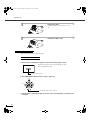
Notations used in this Owner’s Manual
Indications
Indicates procedures where personal injury or damage to the projector may occur if the
procedures are not followed correctly.
Indicates additional information and points which may be useful to know regarding a topic.
Indicates that an explanation of the underlined word or words in front of this symbol appears
in the glossary of terms.
Refer to the “Glossary” in the “Appendices”. (p.67)
[(Button name)],
ZOOM
"(Menu name)"
Indicates buttons on the remote control or the projector's control panel.
Example: [Menu]
Indicates menu items.
Example: "Image" - "Color Adjustment"
LPX-510_E.book Page 1 Wednesday, January 21, 2004 10:58 AM
Turning On the Projector....................................................................................6
Connecting the Power Cord ..................................................................................... 6
Turning On the Power and Projecting Images.......................................................... 7
Turning Off the Projector....................................................................................9
Adjusting the Screen Image ............................................................................11
Adjusting the Image Size (Zoom adjustment)........................................................ 11
Projection image position adjustment (Lens shift)................................................. 12
Correcting Keystone Distortion (Keystone) ........................................................... 13
Displaying a Test Pattern........................................................................................ 14
Adjusting the Image Quality.............................................................................16
Focus adjustment.................................................................................................... 16
Brightness adjustment (Iris adjustment)................................................................. 17
Selecting the picture mode ..................................................................................... 18
Selecting the Image Aspect Ratio .......................................................................... 19
Advanced Operations
Functions for Enhancing Projection .................................................................24
Description of Functions ........................................................................................ 24
Saving and Retrieving Image Quality Settings (Memory Save) ............................ 26
Using the Menu Functions ...............................................................................28
List of Menus ......................................................................................................... 28
"Image" Menu ........................................................................................................ 30
"Setup" Menu ......................................................................................................... 32
"Info" Menu............................................................................................................ 36
"Reset" Menu ......................................................................................................... 36
Using the Menus..................................................................................................... 37
Troubleshooting
When Having Some Trouble ............................................................................42
When the Indicators Provide No Help .............................................................44
Problems relating to images ................................................................................... 44
Problems when projection starts ............................................................................ 48
Problems with the remote control .......................................................................... 48
Advanced Operations
Basic Operations
Troubleshooting
Notes on Handling and Storage ........................................................................2
Accessories .......................................................................................................3
Features of the Projector ...................................................................................4
Basic Operations
Contents
Maintenance ....................................................................................................50
Cleaning ................................................................................................................. 50
Replacing Consumables ......................................................................................... 52
If vertical stripe interference appears in the projected images............................... 56
Optional Accessories.......................................................................................58
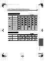
List of Supported Signal Resolutions ..............................................................59
Component Video/RGB Video............................................................................... 59
Composite Video/S-Video...................................................................................... 59
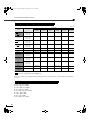
Analog-RGB signals/signals input to the HDMI port ............................................ 60
Range of compatible formats for HDMI port input signals ................................... 60
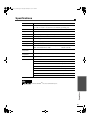
Specifications ..................................................................................................61
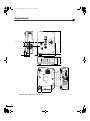
Appearance .....................................................................................................62
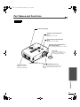
Part Names and Functions ..............................................................................63
Front/Top ................................................................................................................ 63
Control Panel.......................................................................................................... 64
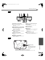
Rear ........................................................................................................................ 65
Base ........................................................................................................................ 65
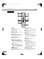
Remote Control ...................................................................................................... 66
Glossary ..........................................................................................................67
Appendices
Appendices
1
LPX-510_E.book Page 2 Wednesday, January 21, 2004 10:58 AM
Notes on Handling and Storage
Be sure to observe the following precautions to avoid malfunctions, operating errors or damage to the projector.
Notes on Handling and Storage
• Do not set up the projector near high-voltage electrical wires or sources of magnetic fields.
These may interfere with correct operation.
• Do not touch the lens with bare hands.
•
•
•
•
•
If fingerprints or grease get onto the lens, it can interfere with the quality of the projected images. Attach the lens
cover to the lens when the projector is not in use.
During projection, some points (dots) may appear lit at all times, or they may be dark at all times.
This is caused by the characteristics of the LCD panel, and is not a sign of a malfunction. The LCD panel is
manufactured using extremely high-precision technology. However, black dots may appear on the panel, or some
red, blue or green dots may light extremely brightly at times. Furthermore, sometimes stripe-shaped color
irregularities or brightness irregularities may also appear.
Remove the batteries from the remote control before storage.
If the batteries are left in the remote control for long periods, they may leak.
Always attach the lens cap to the lens when not using the projector, to prevent the lens from becoming dirty or
damaged.
The mercury lamp that is used as the light source for the projector deteriorates as a result of impacts or
damage, and also naturally over time as it is used. It may explode with a loud noise or stop illuminating, or the
flickering may increase or illumination may stop, and these indicate the end of the lamp's operating life.
At such times, the amount of time remaining before the lamp breaks or stops working may vary greatly depending
on the individual lamp characteristics and the operating environment. These are normal characteristics of mercury
lamps. You should always have a spare lamp ready in case it is needed.
YAMAHA takes no responsibility for loss or damage caused by damage to the projector or operating failures
outside normal service warranty conditions.
Lamp Operating Errors
The mercury lamp that is used as the light source for this projector may stop operating on occasions. This is a normal
characteristic of mercury lamps. If the lamp does not turn on when the projector's power is turned on, remove the
lamp and check if it is broken. If the lamp is not broken, reinstall it. Refer to "Replacing the Lamp" on page 53 of this
manual for instruction on removing and reinstalling the lamp.
If the lamp is broken, replace it with a new lamp. It is recommended that you have a spare lamp ready at all times in
case it is needed.
Notes on Carrying the Projector
• Turn off the projector power and then disconnect the power cord from the electrical outlet.
Furthermore, check that all other cables have been disconnected.
• Attach the lens cap to the lens.
• Retract the adjustable foot.
Notes when transporting the projector
When packing up the projector in its container for transportation, use the lens shift function to lower the lens fully.
2
LPX-510_E.book Page 3 Wednesday, January 21, 2004 10:58 AM
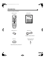
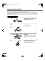
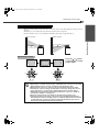
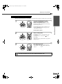
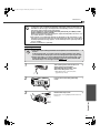
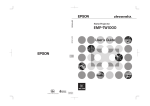
Accessories
Check the included accessories
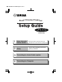
Remote control
Setup guide
Home Cinema Projector
IRIS
ZOOM
FOCUS
SETTING
PATT
LPX-510
MENU
ESCAPE
1
Before Using the
Remote Control
2
Setup
3
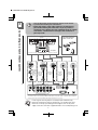
Connecting to a home theater system
4
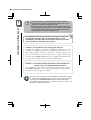
Connecting to a Computer
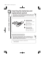
Inserting the batteries and replacement period
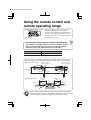
Using the remote control and remote operating range
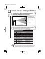
Screen Size and Setting-up Distance
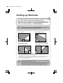
Setting-up Methods
INPUT
ASPECT
LIGHT
HIDE
S VIDEO
A
HDMI
VIDEO
B
D4
INPUT
MEMORY
1
2
3
4
5
6
Battery (AA) x 2
Power cord
* The shape of the power cord will vary
depending on the market destination.
Lens cap
Trigger-out DC plug
(for USA only)
When not using the projector, always be sure to
attach the lens cap in order to protect the lens.
3
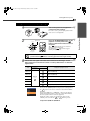
LPX-510_E.book Page 4 Wednesday, January 21, 2004 10:58 AM
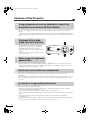
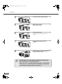
Features of the Projector
Image appearance can be selected to match the
projection environment (Picture Mode)
The projector is equipped with a unique CB (color balance) filter that enhances the color reproduction of
images.
It is ideal for use in providing the optimum image effects for the projection environment when viewing images
such as games, sporting competitions and movies. It makes other troublesome color adjustments unnecessary.
(p.18)
Equipped with a wideangle lens shift function
The lens shift function allows you to adjust the
position of the projected images vertically and
horizontally without distorting the images.
This allows the projector to be set up with greater
freedom,
even if it is suspended from a ceiling or at an angle
to the screen. (p.12)
Wide range of brightness
adjustments
The image brightness can be adjusted within a wide range. Optimum images can be obtained even if using
the projector in a bright environment for watching videos or games, or in a dark environment such as when
creating the atmosphere of a home theatre. (p.30)
Electronic zoom and focus adjustment
The projector's control panel and the accessory remote control can be used for easy zoom and focus
adjustments.
For zoom adjustment, a high magnification lens is provided to allow images to be increased in size by up to 1.5
times, so that images can be projected onto an 80" screen even at a distance of approximately 2.5 m (8.2 ft.).
(p.11, 16)
A variety of image setting functions
Many other functions are available as follows.
Progressive and Motion Detection functions allow you to obtain ideal results both for images with large
amounts of movement and for still images. (p.32)
An aspect function that allows images to be viewed in wide-screen format. (p.19)
Memory functions that allow adjustment results to be stored and later retrieved easily using the remote control.
(p.26)
Key lock function that locks the control panel so that settings cannot be changed accidentally after
adjustment. (p.34)
Adoption of a special high-resolution DCDi video circuit developed by Faroudja. This circuit greatly reduces
the jagged edges that resulted from conventional progressive conversion. (p.32)
4
LPX-510_E.book Page 5 Wednesday, January 21, 2004 10:58 AM
Basic Operations
This chapter describes basic operations such as turning the projector on and off and adjusting the
projected images.
Turning On the Projector .................................................................. 6
•
•
Connecting the Power Cord ........................................................................................6
Turning On the Power and Projecting Images ..........................................................7
Turning Off the Projector .................................................................. 9
Adjusting the Screen Image ........................................................... 11
•
•
•
•
Adjusting the Image Size (Zoom adjustment) .........................................................11
Projection image position adjustment (Lens shift)..................................................12
Correcting Keystone Distortion (Keystone) .............................................................13
Displaying a Test Pattern ...........................................................................................14
Adjusting the Image Quality........................................................... 16
•
•
•
•
Focus adjustment........................................................................................................16
Brightness adjustment (Iris adjustment) .................................................................17
Selecting the picture mode.........................................................................................18
Selecting the Image Aspect Ratio..............................................................................19
• Normal mode...................................................................................................................................20
• Squeeze mode..................................................................................................................................20
• Zoom mode .....................................................................................................................................20
• Smart Zoom mode...........................................................................................................................21
• Through mode .................................................................................................................................21
• Squeeze Through mode...................................................................................................................21
5
LPX-510_E.book Page 6 Wednesday, January 21, 2004 10:58 AM
Turning On the Projector
This section describes the procedure from turning on the power to projecting images.
Be sure to read the Safety Instructions in this manual for details on safe handling when
using the projector.
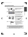
Connecting the Power Cord
1
Check that the power is turned off for all
components connected to the
projector.
2
Connect the computer or other video
source to the projector.
Refer to the Setup Guide.
3
Remove the lens cap.
4
Connect the accessory power cord to
the projector.
Check that the power cord connector is facing the
same way as the power inlet on the projector, and
then insert the power cord connector securely into
the projector.
5
Lights orange
STANDBY/ON
ESCAPE
MENU
PATTERN
SETTING
ASPECT
6
INPUT
Connect the other end of the power
cord to a grounded electrical outlet.
The
indicator will light orange and the
projector will switch to standby mode.
LPX-510_E.book Page 7 Wednesday, January 21, 2004 10:58 AM
Turning On the Projector
Turning On the Power and Projecting Images
1
2
Lights green
STANDBY/ON
ESCAPE
MENU
IRIS
PATTERN
ZOOM
FOCUS
SETTING
PATT
SETTING
MENU
ESCAPE
ASPECT
INPUT
Projector
Basic Operations
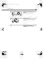
Turn on the power for all equipment
connected to the projector.
For a video source, press the [Play] button at the
video source to start playback.
Press the [STANDBY/ON] button on the
projector's control panel or the
button on the remote control to turn on
the power.
The
indicator flashes green, and after a
short period projection starts.
Check that the
indicator has stopped
flashing and lights green.
Remote control
The buttons on the remote control and the projector's control panel cannot be
operated while the
indicator is flashing green. Wait until it lights steadily.
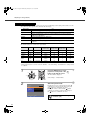
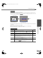
3
If more than one signal source has been connected or the images are not
being projected, use the remote control or control panel buttons to select the
signal source.
Button to press
Port
Projector or
remote control
Display at top-right of screen
Remote control
INPUT A
A
INPUT A (Component) or INPUT A (RGB TV) ,
INPUT A (RGB PC)
INPUT B
B
INPUT B (Component) or INPUT B (RGB TV) ,
INPUT B (RGB PC)
S VIDEO
VIDEO
D4 VIDEO
HDMI
Source
Input A
Input B
S-Video
Video
D4
HDMI
[INPUT]
or
INPUT
S VIDEO
S-Video
VIDEO
Video
D4
HDMI
D4 (Component)
HDMI (Component) , HDMI (RGB TV) , HDMI (RGB PC)
If you press the [INPUT] button on the projector's control panel or
the
button on the remote control, the selection menu will be
displayed.
If you select "INPUT A" or "INPUT B", a menu for selecting the
signal format will be displayed. Select the format which matches
the video signals from the connected equipment.
If using the remote control, the signal format changes in the
following order each time the A or B button is pressed.
INPUT
Component → RGB TV → RGB PC
7
LPX-510_E.book Page 8 Wednesday, January 21, 2004 10:58 AM
Turning On the Projector
• If only one signal source has been connected, the signals from that source will be
projected without needing to press one of the above buttons.
• If video signals are being input to several input ports simultaneously, interference
between the various signals may occur, and this may cause interference in the
projected images. If this happens, turn off the power supply or disconnect the
video equipment which is not currently being used.
• If the "No Signal." message does not disappear, check the connections again.
No images will be projected during the time that it takes for signals to be input from
the video source.
• If a laptop computer or a computer with an LCD screen has been connected to the
projector, the images may not be projected straight away. After making the
connections, check that the computer has been set up to output signals.
The following table shows examples of how to toggle output settings. For details,
refer to the section of the documentation provided with your computer under a
heading such as "External output", "Connecting an external monitor" or similar.
NEC
[Fn]+[F3]
8
Panasonic
[Fn]+[F3]
Toshiba
[Fn]+[F5]
IBM
[Fn]+[F7]
Sony
[Fn]+[F7]
Fujitsu
Macintosh
[Fn]+[F10]
After startup, change the
Control Panel adjustments
so that Mirroring is active.
LPX-510_E.book Page 9 Wednesday, January 21, 2004 10:58 AM
Turning Off the Projector
Follow the procedure below to turn off the power of the projector.
1
Turn off the power for the signal
sources that are connected to the
projector.
Check that the power for all connected
components has been tuned off.
Yes
No
3
: Press STANDBY/ON button
: Press any other button
STANDBY/ON
ESCAPE
MENU
IRIS
PATTERN
ZOOM
FOCUS
SETTING
PATT
SETTING
ESCAPE
ASPECT
MENU
INPUT
Projector
4
Press the [STANDBY/ON] button on the
projector's control panel or the
button on the remote control.
The confirmation message shown at left will
appear.
If you do not want to turn off the power, press any
button except the [STANDBY/ON] button.
If you do not carry out any operation, the
message will disappear after seven seconds. (The
power will not turn off at this time.)
Power OFF?
Remote control
Basic Operations
2
Press the [STANDBY/ON] button on the
projector's control panel or the
button on the remote control once
more.
The lamp will switch off, the
indicator will
flash orange and cool-down will start.
The remote control and the projector's control
panel cannot be operated while cool-down is in
progress (about 30 seconds).
After cool-down is complete, the
indicator
will change to lit orange (standby mode).
If not using the projector for long
periods of time, disconnect the power
cord plug from the wall outlet.
Always make sure that the projector is in standby
mode before disconnecting the power cord.
The
indicator will continue to light for a
short period after the power cord is disconnected,
and then it will turn off.
Do not disconnect the power cord while the projector is projecting or while
cool-down is in progress. If the power cord is disconnected at times such as
when projection is in progress, wait for the lamp to cool down (normally about
one hour is required) before turning the power back on again. If the power is
turned off and on before the lamp has cooled down, it may result in lamp
operating errors. Refer to "Lamp operating error" on page 42.
9
LPX-510_E.book Page 10 Wednesday, January 21, 2004 10:58 AM
Turning Off the Projector
5
Retract the front adjustable foot if it is
extended.
Turn the front adjustable foot to retract it.
Retract
6
7
10
Retract
Attach the lens cap.
Attach the lens cap to the lens when not using the
projector, in order to stop the lens from getting
dusty or dirty.
Disconnect the cords that are
connecting the projector and other
equipment.
LPX-510_E.book Page 11 Wednesday, January 21, 2004 10:58 AM
Adjusting the Screen Image
You can adjust the screen image in order to obtain the best possible picture.
Adjusting the Image Size (Zoom adjustment)
The size of the projected image is basically determined by the distance from the projector to the screen.
(Refer to the Setup Guide.)
The following procedures explain how to adjust the screen image once the projector itself has been set up.
STANDBY/ON
ESCAPE
MENU
IRIS
PATTERN
ZOOM
FOCUS
SETTING
PATT
SETTING
MENU
ESCAPE
ASPECT
Press the [SETTING] button on the
projector's control panel or the ZOOM
button on the remote control.
An adjustment icon will be displayed over the
image during projection.
Basic Operations
1
INPUT
Projector
Remote control
The adjustment mode changes as follows each
time the [SETTING] button on the projector's
control panel is pressed.
Zoom → Focus → Iris
2
STANDBY/ON
ESCAPE
IRIS
SETTING
PATT
ESCAPE
MENU
ASPECT
INPUT
MENU
PATTERN
SETTING
ASPECT
INPUT
LIGHT
Projector
3
HIDE
Remote control
STANDBY/ON
ESCAPE
MENU
IRIS
PATTERN
ZOOM
FOCUS
SETTING
PATT
Adjust the image size.
If using the projector's control panel, press the
or button to adjust the image size.
If using the remote control, tilt the button to
adjust the image size.
Adjustment is also possible while a test pattern is
being projected. (p.14)
Exit adjustment mode.
Press the [ESCAPE] button on the projector's
control panel or the ZOOM button on the remote
control.
SETTING
ESCAPE
ASPECT
MENU
INPUT
Projector
Remote control
When the electronic zoom lock is set to
"ON", the projection size cannot be
adjusted.
The
symbol will be displayed at this
time. To carry out adjustments, change
the electronic zoom lock setting to
"OFF". (p.34)
11
LPX-510_E.book Page 12 Wednesday, January 21, 2004 10:58 AM
Adjusting the Screen Image
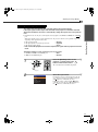
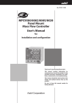
Projection image position adjustment (Lens shift)
The lens shift function can be used to adjust the position of projected images when the projector has been set
up in places such as the following.
• When the projector is suspended from a ceiling
• When the screen is higher than the projector
• When the projector is at an angle to the screen so that people can sit directly in front to view the screen
• When the projector is on top of a desk or similar
The lens shift function can move the lens horizontally and vertically to adjust the image position without
causing keystone distortion. Use the two lens shift dials to adjust the position of the projected images.
* At the time of shipment from the factory, the vertical lens shift position is set to the lowest position, so
move it to the center position before carrying out adjustment.
Horizontal lens shift: The projector can be set up
anywhere between the left and
right edges of the screen.
Vertical lens shift: The projector can be set up anywhere
from the top edge of the screen to half
the height of the screen below the
bottom edge.
Lowest lens
position
Lens at maximum down
(Can be shifted by a
maximum of half the
screen width)
Highest lens
position
Lens at maximum right
(Can be shifted by a
maximum of half the
screen width)
Lens at maximum left
(Can be shifted by a
maximum of half the screen
width)
Lens at maximum up
(Can be shifted by a
maximum of one
screen width)
* The dotted lines indicate the projection range from the lens center position.
* The lens cannot be shifted to the maximum vertical and horizontal positions at the same time.
Adjustment procedure
Left
Down
Right
Up
Turn the two lens shift dials to adjust.
When the lens shift dial is turned, a point of
resistance will be felt. This indicates the
approximate center point for the range of
adjustment. In addition, if the lens shift dial
becomes hard to turn further and the image
position stops changing, no further adjustment is
possible.
If the projected images are tilted horizontally, use the left and right front adjustable feet to
adjust the projector so that it is level.
Front
adjustable feet
Front
adjustable feet
Extend
12
Retract
Extend
Retract
LPX-510_E.book Page 13 Wednesday, January 21, 2004 10:58 AM
Adjusting the Screen Image
Correcting Keystone Distortion (Keystone)
When you wish to adjust the projection above or below the range of lens shift adjustment set the projector at
an angle.
When the projector is angled, the projected image may distort into a trapezoid.
Keystone distortion can be corrected within a maximum vertical angle of approximately 15°.
Approx. 15°° above
Basic Operations
Approx. 15°° below
15°
15°
Adjustment procedure
Press the
or
button
on the projector's control
panel to adjust.
STANDBY/ON
ESCAPE
STANDBY/ON
MENU
PATTERN
ESCAPE
SETTING
ASPECT
INPUT
LAMP/COVER TEMP/FAN
Projector
MENU
PATTERN
SETTING
ASPECT
INPUT
LAMP/COVER TEMP/FAN
Projector
• The image quality will be lower than if the lens shift function is used.
• When the lens is shifted to the left or right, complete keystone correction is not possible.
•
•
•
•
•
When making keystone corrections set the lens at the center left to right.
When keystone correction is carried out, the projected image will become smaller.
The keystone correction settings are memorized, so that if you change the position or
angle of the projector, you may need to readjust the keystone correction settings.
If the images become uneven in appearance after keystone correction is carried out,
decrease the “Sharpness” setting. (p.30)
Keystone correction can also be carried out using the projector menu. (p.33)
If the value displayed in the gauge on the screen stops changing when horizontal or
vertical keystone correction is being carried out, it indicates that the limit for horizontal
or vertical keystone correction has been exceeded. Check that the projector has not
been set up at an angle which exceeds the proper limit.
13
LPX-510_E.book Page 14 Wednesday, January 21, 2004 10:58 AM
Adjusting the Screen Image
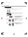
Displaying a Test Pattern
You can project a test pattern at times such as when setting up the projector in order to correct keystone
correction and to make line menu adjustments.
• Crosshatch
This can be used to check whether the projector is tilted or set up
vertically in front of the screen.
•
Grayscale pattern
This is used when adjusting brightness or when adjusting image quality
or color tone.
The adjustment is made using the line menu. Adjustments other than
brightness are not possible when no image signals are being input.
1
Press the [PATTERN] button on the
projector's control panel or the PATT
button on the remote control.
A pattern select menu will be displayed.
Test Pattern
Cross-hatching
Gray Scale
Exit
2
STANDBY/ON
ESCAPE
IRIS
SETTING
MENU
ASPECT
INPUT
MENU
PATTERN
SETTING
ASPECT
LIGHT
STANDBY/ON
ESCAPE
HIDE
Remote control
IRIS
SETTING
PATT
ESCAPE
MENU
ASPECT
INPUT
MENU
PATTERN
SETTING
ASPECT
INPUT
LIGHT
Projector
14
Select a pattern.
If using the projector's control panel, press the
or button.
If using the remote control, tilt the button
vertically.
INPUT
Projector
3
PATT
ESCAPE
HIDE
Remote control
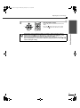
Confirm the pattern selection.
Press the
button on the projector's control
panel or the
button on the remote control.
LPX-510_E.book Page 15 Wednesday, January 21, 2004 10:58 AM
Adjusting the Screen Image
4
STANDBY/ON
ESCAPE
IRIS
SETTING
PATT
ESCAPE
MENU
ASPECT
INPUT
MENU
PATTERN
SETTING
ASPECT
Exit the pattern display.
Display the pattern select menu and then select
"Exit".
Press the
button on the projector's control
panel or the
button on the remote control.
INPUT
LIGHT
Projector
HIDE
Remote control
Basic Operations
The full menu cannot be displayed while a test pattern is being projected. If setting is
required, press the
button on the projector's control panel or the
button on the
remote control to display the line menu, and then make the setting.
If correcting keystone distortion while a test pattern is being projected, press the
or
button on the projector's control panel to make the setting. The remote control cannot be
used for making this setting.
15
LPX-510_E.book Page 16 Wednesday, January 21, 2004 10:58 AM
Adjusting the Image Quality
The quality of the screen images can be adjusted as follows.
Focus adjustment
1
STANDBY/ON
ESCAPE
MENU
IRIS
PATTERN
ZOOM
FOCUS
SETTING
PATT
SETTING
MENU
ESCAPE
ASPECT
Press the [SETTING] button on the
projector's control panel or the FOCUS
button on the remote control.
An adjustment icon will be displayed over the
image during projection.
INPUT
Projector
Remote control
The adjustment mode changes as follows each
time the [SETTING] button on the projector's
control panel is pressed.
Zoom → Focus → Iris
2
STANDBY/ON
ESCAPE
IRIS
SETTING
MENU
ASPECT
INPUT
MENU
PATTERN
SETTING
ASPECT
INPUT
LIGHT
Projector
3
HIDE
Remote control
STANDBY/ON
ESCAPE
MENU
IRIS
PATTERN
ZOOM
FOCUS
SETTING
PATT
Adjust the focus.
If using the projector's control panel, press the
or button to adjust the image size.
If using the remote control, tilt the
button to
adjust the image size.
Adjustment is also possible while a test pattern is
being projected.
Exit adjustment mode.
Press the [ESCAPE] button on the projector's
control panel or the FOCUS button on the remote
control.
SETTING
ESCAPE
ASPECT
MENU
INPUT
Projector
16
PATT
ESCAPE
Remote control
When the electronic focus lock is set to
"ON", the projection size cannot be
adjusted.
The
symbol will be displayed at this
time. To carry out adjustments, change
the focus lock setting to "OFF". (p.34)
LPX-510_E.book Page 17 Wednesday, January 21, 2004 10:58 AM
Adjusting the Image Quality
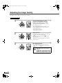
Brightness adjustment (Iris adjustment)
The brightness of the images can be adjusted.
When projecting in dark rooms or onto small screens and the images appear too bright, decrease the setting.
STANDBY/ON
ESCAPE
MENU
IRIS
PATTERN
ZOOM
FOCUS
SETTING
PATT
SETTING
MENU
ESCAPE
ASPECT
Press the [SETTING] button on the
projector's control panel or the IRIS
button on the remote control.
The line menu will be displayed over the images
that are being projected.
INPUT
Projector
Remote control
The adjustment mode changes as follows each
time the [SETTING] button on the projector's
control panel is pressed.
Basic Operations
1
Zoom → Focus → Iris
2
STANDBY/ON
ESCAPE
IRIS
SETTING
PATT
ESCAPE
MENU
ASPECT
INPUT
MENU
PATTERN
SETTING
ASPECT
INPUT
LIGHT
Projector
3
HIDE
Remote control
STANDBY/ON
ESCAPE
MENU
IRIS
PATTERN
ZOOM
FOCUS
SETTING
PATT
Select a setting value.
If using the projector's control panel, press the
- or + button.
If using the remote control, tilt the
button
horizontally.
Adjustment is also possible while a test pattern is
being projected.
Exit adjustment mode.
Press the [ESCAPE] button on the projector's
control panel or the IRIS button on the remote
control.
SETTING
ESCAPE
ASPECT
MENU
INPUT
Projector
Remote control
The Lamp Power menu can also be used to make the adjustment. (p.34)
17
LPX-510_E.book Page 18 Wednesday, January 21, 2004 10:58 AM
Adjusting the Image Quality
Selecting the picture mode
The following six picture modes have been preset for use with images with varying characteristics. Use the
select menu to select a picture mode that best suits the images.
Mode name
Use
Dynamic
Ideal for viewing games and sporting competitions in bright rooms.
Bright
Ideal for viewing movies in bright rooms.
Standard
Ideal for viewing in dark rooms. It is recommended that you use this mode when
making color adjustments.
Cinema
Ideal for watching movies in dark rooms.
Cinema Black
Ideal for watching movies in rooms that are completely shaded.
PC
This mode is ideal for playing back sRGB-compliant images such as those from a
computer.
The default settings for each mode are given below.
CB Filter
Gamma
Abs. Color Temp.
(default value)
Iris
(default value)
Flesh Tone
(default value)
Lamp Power
Dynamic
OFF
-
7000k
100
5
100
Bright
OFF
-
7000k
100
5
100
Standard
ON
2.2X (basic)
6500k
100
3
75
Cinema
ON
-
6500k
100
3
75
Cinema
Black
ON
-
6500k
75
3
75
PC
ON
2.2X (fixed)
6500k
100
3
75
Mode name
* The CB (color balance) filter is fixed for each mode.
* If the picture mode is set to "PC", then the "Gamma", "Abs. Color Temp." and "Flesh Tone" settings cannot
be adjusted.
1
STANDBY/ON
ESCAPE
IRIS
SETTING
MENU
ASPECT
INPUT
MENU
PATTERN
SETTING
ASPECT
INPUT
LIGHT
Projector
2
:Select
Press the [MENU] button on the
projector's control panel or the
button on the remote control.
The menu will be displayed.
MENU
Select "Image" - "Picture Mode".
HIDE
Remote control
[Picture Mode]
Dynamic
Bright
Standard
Cinema
Cinema Black
PC
ESC:Return
18
PATT
ESCAPE
Return
:Setting
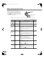
Select the picture mode.
If using the projector's control panel, press the
or button to select the picture mode, and press
the
button to confirm the selection.
If using the remote control, tilt the
button
vertically to select the picture mode, and press
the
button to confirm the selection.
You can also make the setting from the
line menu. (p.38)
LPX-510_E.book Page 19 Wednesday, January 21, 2004 10:58 AM
Adjusting the Image Quality
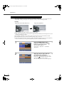
Selecting the Image Aspect Ratio
This selects the ratio between the height and width of the projected images.
If the input signal includes aspect ratio information, the projector's automatic mode will
detect this information and use it to automatically change the aspect ratio to the optimum
ratio.
•
Basic Operations
Automatic mode can only be set when signals are being input to the VIDEO, S VIDEO, D4 or HDMI
port.
When such signals are projected in automatic mode, the projector switches to the optimum aspect ratio
depending on the signal as shown below.
→ Normal
• For 4:3 input signals
→ Squeeze
• For input signals recorded in squeeze mode
→ Zoom
• For letterbox input signals
* If the connected equipment is not EIAJ-compliant, the signals will be projected in Normal
mode.
The default settings for each connection port are as follows.
•
•
→ Auto
→ Normal
VIDEO, S VIDEO, D4 and HDMI ports
INPUT A and INPUT B ports
1
ESCAPE
MENU
ESCAPE
MENU
ASPECT
PATTERN
SETTING
INPUT
ASPECT
ASPECT
INPUT
LIGHT
S VIDEO
Projector
2
Press the [ASPECT] button on the
projector's control panel or the
button on the remote control.
The select (Resize) menu will be displayed.
Resize
Auto
Normal
Squeeze
Zoom
Through
Squeeze Through
Smart Zoom
HIDE
A
HDMI
Remote control
Select the aspect mode.
If using the projector's control panel, press the
or button to select the aspect Mode, and press
the
button to confirm the selection.
If using the remote control, tilt the
button
vertically to select the aspect Mode, and press
the
button to confirm the selection.
19
LPX-510_E.book Page 20 Wednesday, January 21, 2004 10:58 AM
Adjusting the Image Quality
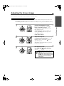
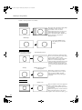
Details of each aspect ratio are as follows.
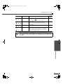
Normal mode
4:3 image
The aspect ratio of the images being input
is maintained, and the images are
projected into a 16:9 screen area.
If projecting images in 4:3 mode such as
normal TV broadcasts and computer
images, black bands will be displayed at
the left and right as shown in the
illustration at left.
HDTV images
If projecting HDTV images,
they will be projected in 16:9
format.
Squeeze mode
When projecting 4:3 TV images
recorded in squeeze mode
Viewed using the projector
This is used when projecting images that
have been recorded in squeeze mode using
a video camera or DVD recorder.
When viewing images recorded in squeeze
format on a 4:3 TV, the images will
compressed in the horizontal direction and
elongated vertically. If squeeze mode is
selected for the projector, the images can
be projected in their original wide format
(16:9).
4:3 image
When the projector's squeeze
mode is applied
When images output in 4:3 format are
projected using the projector's squeeze
mode, the images will be extended
horizontally and the image will appear
elongated.
Zoom mode
Letterbox images
Resized to 16:9
Images in letterbox mode from equipment
such as a DVD player will be cut at top
and bottom by a fixed amount and resized
to 16:9 format.
If this causes captions to be truncated from
images that have them, use the "Zoom
Caption" menu command to adjust. (p.33)
20
LPX-510_E.book Page 21 Wednesday, January 21, 2004 10:58 AM
Adjusting the Image Quality
Smart Zoom mode
4:3 image
Basic Operations
Images in 4:3 format such as normal TV
broadcasts are extended horizontally, with
less elongation in the middle and more
elongation at the edges.
This is useful for when 4:3 images are
projected onto a wide screen. Because
there is almost no distortion due to
enlargement in the middle of the images,
the images appear close to what they
would be at their original size. And
because both ends of the images are
enlarged, movement at the edges of the
images appears faster and gives an
impression of greater speed, making it
ideal for viewing sporting events.
*If keystone correction has been carried
out, Smart Zoom mode cannot be
selected.
Through mode
If the input signal resolution is 1280 x 720
dots or less, the images are projected onto
the screen with the input signal resolution
unchanged. Because of this, the size of the
displayed images will change depending
on the input resolution.
The picture quality will be the clearest for
portions of the image that have not been
resized horizontally or vertically.
Squeeze Through mode
If the input signal resolution is 1280 x 720
dots or less, the input signal resolution is
elongated horizontally and the images are
projected at an aspect ratio of 16:9.
Because of this, the size of the displayed
images will change depending on the input
resolution.
The portions that are not vertically resized
will appear with higher image quality.
21
LPX-510_E.book Page 23 Wednesday, January 21, 2004 10:58 AM
Advanced Operations
This chapter describes functions for enhancing the projection of images, and how to use the menus.
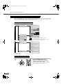
Functions for Enhancing Projection ............................................. 24
•
Description of Functions ............................................................................................24
• White Level Adjustment .................................................................................................................24
• Black Level Adjustment ..................................................................................................................24
• Input Level Adjustment...................................................................................................................24
• Contrast Adjustment........................................................................................................................24
• Absolute Color Temperature and Flesh Tone Adjustment ..............................................................25
• RGB adjustment ..............................................................................................................................25
•
Saving and Retrieving Image Quality Settings
(Memory Save)............................................................................................................26
• Settings that can be saved in memory .............................................................................................26
• Storing image quality settings .........................................................................................................26
• Retrieving Saved Image Quality Settings........................................................................................27
Using the Menu Functions ............................................................. 28
•
•
List of Menus ..............................................................................................................28
"Image" Menu............................................................................................................30
• Picture Quality.................................................................................................................................30
• Color Adjustment ............................................................................................................................31
• Picture Mode ...................................................................................................................................31
• Memory Save ..................................................................................................................................31
• Auto Setup.......................................................................................................................................31
• Reset ................................................................................................................................................31
•
"Setup" Menu.............................................................................................................32
• Signal...............................................................................................................................................32
• Screen ..............................................................................................................................................33
• Operation.........................................................................................................................................34
• User’s Logo .....................................................................................................................................35
• On-Screen Display ..........................................................................................................................35
• Input Signal .....................................................................................................................................36
• Language .........................................................................................................................................36
• Reset ................................................................................................................................................36
•
•
"Info" Menu................................................................................................................36
"Reset" Menu .............................................................................................................36
• Lamp-Hours Reset...........................................................................................................................36
• Memory Reset .................................................................................................................................36
• All Reset..........................................................................................................................................36
•
Using the Menus .........................................................................................................37
• Displaying and Operating Full Menus ............................................................................................37
• Displaying and Operating Line Menus ...........................................................................................38
2
LPX-510_E.book Page 24 Wednesday, January 21, 2004 10:58 AM
Functions for Enhancing Projection
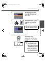
This section explains how to use the functions for adjusting the picture quality to the optimum quality.
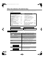
Description of Functions
White Level Adjustment
Adjusts the brightness of bright shades without changing the black level.
Use the "Image" - "Picture Quality" - "Input Adjustment" - "White Level/Black Level" - "White Level"
menu item to change the setting. (p.30)
If adjusted to the + side, the luminosity of light scenes
increases and contrast become clearer, but differences in
light tones are reduced.
Brightness
When adjusted
to the + side
When adjusted
to the - side
If adjusted to the - side, differences in light areas become
more distinct, but contrast is reduced.
Input signal
Black Level Adjustment
Adjusts the brightness of dark shades without changing the white level.
Use the "Image" - "Picture Quality" - "Input Adjustment" - "White Level/Black Level" - "Black Level" menu
item to change the setting. (p.30)
If adjusted to the + side, the luminosity of dark scenes
increases and different tones become clearer, but
contrast is reduced.
Brightness
When adjusted
to the + side
If adjusted to the - side, the brightness of dark shades is
reduced and images with greater contrast are obtained,
but differences in dark areas become less distinct.
When adjusted
to the - side
Input signal
Input Level Adjustment
Adjusts the overall brightness of the images.
When the setting is changed to the + side, the images appear brighter overall.
Use the "Image" - "Picture Quality" - "Input Adjustment" - "Input Level/Contrast" - "Input Level" menu item
to change the setting. (p.30)
Contrast Adjustment
Adjusts the difference between bright and dark areas.
When the contrast is increased, sharper images are obtained.
Use the "Image" - "Picture Quality" - "Input Adjustment" - "Input Level/Contrast" - "Contrast" menu item to
change the setting. (p.30)
24
LPX-510_E.book Page 25 Wednesday, January 21, 2004 10:58 AM
Functions for Enhancing Projection
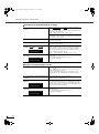
Absolute Color Temperature and Flesh Tone Adjustment
The absolute color temperature adjusts the tint of the whole image.
Flesh tone adjustment adjusts the color of flesh tones to the desired color.
Use the "Image" - "Color Adjustment" - "Abs. Color Temp." and "Flesh Tone" menu items to change the
settings. (p.31)
Change in color
temperature
•
Abs. Color Temp.
If you select a higher value, images appear bluish, and if
you select a lower value, images appear reddish. The
absolute color temperature can be set to one of 12
settings within the range of 5000K to 10000K.
•
Adjusting flesh tones
The CB (color balance) Filter will be applied
automatically so that flesh tones will appear in natural
tints in accordance with the "Picture Mode" setting. If
you would like to adjust the flesh tones to your own
preference, use the "Flesh Tone" setting to adjust. If a
large value is set, flesh tones appear greenish, and if a
smaller value is set, flesh tones appear purplish.
+ flesh tone correction
- flesh tone correction
Dark object locus
RGB adjustment
Offset adjustment
Gain adjustment
Gamma adjustment
Brightness
Brightness
Brightness
When adjusted to
the + side
When adjusted to
the + side
When adjusted
to the - side
Input signal
To make dark areas appear more
clearly, adjust to the + side. If
adjusted to the – side, the whole
image will become sharper, but the
contrast for dark areas will become
poorer.
Advanced Operations
The image brightness can be adjusted by adjusting the individual R (red), G (green) and B (blue) components
of the dark areas (offset), bright areas (gain) and intermediate areas (gamma) respectively. Because such
detailed adjustments are possible, images with greater depth can be obtained. (p.31)
When adjusted
to the + side
When adjusted
to the - side
Input signal
If you would like bright areas to
appear more clearly, change the
setting to the – side. If you change it
to the + side, bright areas will become
whiter, but the contrast will become
poorer.
When adjusted
to the - side
Input signal
If the setting is changed to the – side,
smoother images can be obtained. If
the setting is changed to the + side,
sharper images can be obtained.
25
LPX-510_E.book Page 26 Wednesday, January 21, 2004 10:58 AM
Functions for Enhancing Projection
Saving and Retrieving Image Quality Settings (Memory Save)
Once the "Picture Quality" and "Color Adjustment" menu commands have been used to adjust the projected
images, the adjustment values can then be stored. In addition, the saved data can be retrieved easily, so that
you can enjoy viewing images with the adjusted settings at any time.
Settings that can be saved in memory
•
menus (p.28)
Input Adjustment
"Image" menu
Picture Quality
Iris
Color Intensity
Tint
Sharpness
Tracking
Sync.
Abs. Color Temp.
Color Adjustment
RGB
Picture Mode
Displayed for input sources other than computer
Only displayed for Computer input (does not appear when
signals from the HDMI port are being input)
Auto Setup
Progressive
"Setup" menu
Signal
Motion Detection
Noise Reduction
Overscan
Setup Level
DVI-Video Level
Position
Screen
Zoom Caption
•
Aspect (p.19)
Storing image quality settings
1
STANDBY/ON
IRIS
PATT
Press the [MENU] button on the
projector's control panel or the
button on the remote control.
The menu will be displayed, with the adjustment
values appearing as are currently set.
MENU
ESCAPE
MENU
ASPECT
INPUT
MENU
PATTERN
SETTING
ASPECT
INPUT
LIGHT
Projector
26
SETTING
ESCAPE
HIDE
Remote control
LPX-510_E.book Page 27 Wednesday, January 21, 2004 10:58 AM
Functions for Enhancing Projection
Image
Setup
Info
Select "Memory Save" from the submenu of the "Image" menu, and then
press the
button on the projector's
control panel or the
button on the
remote control.
Reset
Return
Picture Quality
Color Adjustment
Picture Mode
Memory Save
Reset
ESC
:Return
3
Dynamic
:Enter
:Select
STANDBY/ON
IRIS
ESCAPE
SETTING
PATT
ESCAPE
MENU
ASPECT
INPUT
MENU
PATTERN
SETTING
ASPECT
INPUT
LIGHT
Projector
Remote control
[Memory]
Memory1
Memory2
Memory3
Memory4
Memory5
Memory6
ESC :Return
HIDE
Select the memory number (1 - 6) to use
for saving the settings, and then press
the
button on the projector's control
panel or the
button on the remote
control.
The icon for the memory number selected will
change from
to .
If you select a memory number that
already contains stored settings, the
previous settings will be cleared and the
current settings will be stored in their
place.
Return
Advanced Operations
2
:Setting
:Select
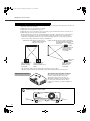
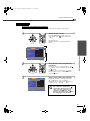
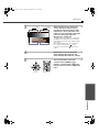
Retrieving Saved Image Quality Settings
S VIDEO
VIDEO
A
HDMI
B
D4
Press one of the remote control
memory buttons [1] to [6]
corresponding to the image quality
settings to be retrieved.
The selected memory number will be displayed at
the top-right of the screen, and the setting values
will be applied to the images that are being
projected.
INPUT
MEMORY
1
2
3
4
5
6
Remote control
Memory 5
• If you press one of the remote control
memory buttons [1] to [6] that has no
stored memory settings, the images
being projected will not change.
• Memory settings that have been
applied to images will be retained even
when the projector's power is turned
off. The same memory adjustment
settings will be applied to images that
are projected the next time the
projector's power is turned on.
• The aspect setting retrieved from
memory may not be applied to the
images if they are 16:9 images or if the
input signal images have a particular
resolution.
27
LPX-510_E.book Page 28 Wednesday, January 21, 2004 10:58 AM
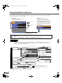
Using the Menu Functions
The menus can be used to make adjustments and settings for items such as the screen, image quality and input signal.
The following two types of menu are available.
•
•
Full menu
This lets you check all menu items
while making settings.
Image
Setup
Info
Top menu
Reset
Return
Picture Quality
Color Adjustment
Picture Mode
Memory Save
Reset
Line menu
This lets you adjust the "Picture
Quality", "Color Adjustment" and
"Picture Mode" items in the "Image"
menu. This menu is useful for checking
how the adjustments affect the images
being projected while the adjustments
are being made.
Sub-menu
Dynamic
Picture Quality
Color Adjustment
Picture Mode
:Select
:Select
:Enter
Navigation Bar
:Enter
Refer to "Using the menus" (p.37) for details on using the menus.
The navigation bar can be turned on and off and the color pattern and display position for menus can be
changed.
"Setup" - "On-Screen Display" - "Menu Position", "Navigation Bar", "Menu Color"
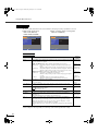
List of Menus
If no image signals are being input, settings other than "Iris" in the "Picture Quality" sub-menu of the
"Image" menu cannot be adjusted. The commands displayed as part of the "Image" menu and "Info" menu
will vary depending on the image signals.
indicates default settings
"Image" menu
Picture Quality
p.30
Input Adjustment
Iris
White Level/Black Level
100 (Depends on picture mode)
Color Intensity
Median value (0)
Tint
Median value (0)
Sharpness
Color Adjustment
Input Level/Contrast
Input Level: Median value (0)
Contrast: Median value (0)
0
Tracking
Depends on input signal
Sync.
Depends on input signal
Abs. Color Temp.
(Varies depending on country of purchase)
7000K(Depends on picture mode)
Abs. Color Temp.
Flesh Tone
RGB
RGB
5 (Depends on picture mode)
p.31
Picture Mode
Dynamic , Bright, Standard,
Cinema, Cinema Black, PC
p.31
Memory Save
28
White Level: Median value (0)
Black Level: Median value (0)
Offset R, G, B: 0
Gain R, G, B: 0
Gamma R, G, B: 2.2
p.31
Auto Setup
p.31
ON , OFF
Reset
p.31
Yes, No
Displayed for input sources other than computer
Only displayed for Computer input
(does not appear when signals from the HDMI
port are being input)
LPX-510_E.book Page 29 Wednesday, January 21, 2004 10:58 AM
Using the Menu Functions
indicates default settings
"Setup" menu
Signal
Progressive
p.32
OFF, Video, Film/Auto
Motion Detection
Median value (3)
Noise Reduction
OFF , NR1, NR2
Overscan
When component video or RGB video signals are input: Standard , Full
When component video signals or RGB video signals are being input to the HDMI port: Auto , Standard, Larger
Setup Level (Varies depending on country of purchase)
0% , 7.5%
DVI-Video Level
Screen
p.33
Normal , Expanded
Position
Vertical Size Minimum value (0)
Zoom Caption
Zoom Position Median value (0)
Keystone
Median value (0)
Projection Front , Front/Ceiling, Rear, Rear/Ceiling
p.34
Sleep Mode
OFF , 5min., 10min., 30min.
Lamp Power
100(Depends on picture mode)
Standby Mode RS-232C Off , RS-232C On
Trigger Out
User's Logo
p.35
ON, OFF
Focus Lock
Zoom Lock
Key Lock
Lamp , Fan , RS-232C
Lock Setting
ON, OFF
ON, OFF
Advanced Operations
Operation
LCD Panel Adjustment
On-Screen
Display
Menu Position
Top-left, Top-center, Top-right, Center-left,
Center-right, Center , Bottom-left, Bottom-center, Bottom-right
Navigation Bar
ON , OFF
p.35
Menu Color
Color 1 , Color 2, Color 3, Color 4
Message
ON , OFF
Black , Blue, Logo
Hide Screen
Startup Screen
Input Signal
Video Signal
p.36
Language
p.36
Reset
p.36
ON , OFF
Auto , NTSC , NTSC4.43, PAL , M-PAL, N-PAL, PAL60, SECAM
Input A
Component , RGB TV, RGB PC
Input B
Component , RGB TV, RGB PC
(Varies depending on country of purchase)
Yes, No
Lamp Hours
Source
Input Signal
ResolutionResolution
Video Signal
Refresh Rate
Sync Info
"Reset" menu
"Info" menu
The message text will be displayed in red when it is time to replace the lamp.
Time from 0H to 10H will be displayed as 0H. From 10H onwards, the display will be in units of 1H.
Lamp-Hours Reset
p.XXX
p.36
Yes, No
Memory Reset
p.36
Yes, No
All Reset
p.36
Yes, No
Only displayed for composite video/S-Video input
Only displayed for component video/RGB-Video/Computer input
Only displayed for Computer input
The "Info" menu is only used to display the projector status.
29
LPX-510_E.book Page 30 Wednesday, January 21, 2004 10:58 AM
Using the Menu Functions
"Image" Menu
The image quality adjustment items are determined by the input port (image signal) that is selected.
•
•
INPUT A, B (Component),
INPUT A, B (RGB TV),
HDMI, VIDEO, S-VIDEO
Image
Setup
Info
Reset
When computer signals are being input
INPUT A, B (RGB PC)
Image
Setup
Info
Return
Picture Quality
Color Adjustment
Picture Mode
Memory Save
Reset
-,+:Select
Reset
Return
Picture Quality
Color Adjustment
Picture Mode
Memory Save
Auto Setup
Reset
Dynamic
:Enter
-,+:Select
Dynamic
:Enter
Picture Quality
Main menu
Input
Adjustment *1
Default
setting
Function
These settings can be adjusted if the output level of the connected equipment is weak and
the images appear dark. The two settings cannot be made simultaneously. You can only
select one of them to be adjusted.
White Level/
Black Level
• White Level/Black Level : These adjust the dark and light areas of images
White Level:
Median value
(0)
Black Level:
Median value
(0)
White Level
Black Level
: Adjusts the brightness of bright shades without changing the black
level.
When the setting is changed to the - side, bright areas become clearer.
: Adjusts the brightness of dark shades without changing the white level.
When the setting is changed to the + side, dark areas become clearer.
• Input Level/Contrast : Adjusts the overall brightness of the images.
: Adjusts the overall brightness of the images.
When the setting is changed to the + side, the images appear brighter
overall.
: Adjusts the difference between bright and dark areas.
When the contrast is increased, sharper images are obtained.
Input Level:
Median value
(0)
Contrast:
Median value
(0)
The brightness of the images can be adjusted.
When projecting in dark rooms or onto small screens and the images appear too bright,
decrease the setting.
100 (Depends
on picture
mode)
Input Level
Contrast
Iris*2
Color Intensity *1 (Setting is only possible when signals other than computer signals are being input.)
This adjusts the color intensity for the images.
Median value
(0)
Tint *1
(Setting is only possible when signals other than computer signals [S-Video
NTSC signals] are being input.)
This adjusts the image tint.
Median value
(0)
Sharpness *1
This adjusts the image sharpness.
0
Tracking *1
(Setting is only possible when computer signals are being input to the INPUT A or
INPUT B port.)
This adjusts the images if vertical stripes appear in the images.
Depends on
input signal
Sync. *1
(Setting is only possible when computer signals are being input to the INPUT A or
INPUT B port.)
This adjusts the images if flickering, fuzziness or interference appear in the images.
• Flickering and fuzziness may also appear in images when the brightness, contrast,
sharpness and keystone correction settings are adjusted.
• Clearer adjustments can be obtained if you adjust the tracking first and then adjust the
sync.
Depends on
input signal
or
*1 The setting values are stored separately for each image source and signal type.
*2 The settings are stored separately for each image source and the picture mode setting.
30
LPX-510_E.book Page 31 Wednesday, January 21, 2004 10:58 AM
Using the Menu Functions
Color Adjustment
If the picture mode is set to "PC", "Color Adjustment" cannot be selected.
Main menu
Abs. Color
Temp. *2
Function
• Abs. Color Temp. : This adjusts the overall tints of the images in accordance with the
images being projected. (p.25)
• Flesh Tone
RGB *1
: This adjusts the flesh tones of people who appear in the images.
(p.25)
This lets you adjust the offset, gain and gamma for each of the R/G/B color components.
(p.25)
Default
setting
7000K
(Varies
depending on
country of
purchase)
(Depends on
picture mode)
5 (Depends
on picture
mode)
Offset R/G/B:
0
Gain R/G/B:
0
Gamma R/G/
B: 2.2
*1 The setting values are stored separately for each image source and signal type.
*2 The settings are stored separately for each image source and the picture mode setting.
Advanced Operations
Picture Mode *1
The picture mode can be selected from six different settings in accordance with the images being projected.
(Default setting: Dynamic) (p.18)
*1 The setting values are stored separately for each image source and signal type.
Memory Save
This can be used to save the current "Image" and "Setup" configuration menu settings and the aspect. (p.26)
Auto Setup *1
(Setting is only possible when computer signals are being input.)
This sets automatic adjustment to on or off in order to set whether the projector automatically adjusts images
to their optimum condition when the input signal is changed. (Default setting: ON)
*1 The setting values are stored separately for each image source and signal type.
Reset
Returns all adjustment values in the "Image" menu (other than the values stored using the "Memory Save"
command) to their default values. "Memory Save" is reset using the "Memory Reset" command. (p.36)
31
LPX-510_E.book Page 32 Wednesday, January 21, 2004 10:58 AM
Using the Menu Functions
"Setup" Menu
Image
Setup
Info
Reset
Return
Signal
Screen
Operation
User's Logo
On-Screen Display
Input Signal
Language
Reset
-,+:Select
English
:Enter
Signal
Main menu
Function
Progressive *1
(Setting is only possible when composite video , S-Video , component video or
480i and 576i RGB video signals are being input.)
: Conversion of interlaced (i) signals to progressive (p) signals is carried
• OFF
out for each field in the screen. This is ideal for using when viewing
images with a large amount of movement.
: IP conversion is carried out. The film judgment function is turned off. This
• Video
is ideal for general video images. The DCDi function operates.
• Film/Auto : Automatically judges the input source if it is a film source or not.
When it is judged as a film, the image equivalent with its original source
will be projected. The DCDi function operates.
Film/Auto
Motion
Detection
(Setting is only possible when composite video, S-Video, component video and 480i and
576i RGB video signals are being input.)
This adjusts the IP conversion settings depending on whether the images contain large
amounts of movement or they are still (or slow) images.
If a smaller value is selected, flickering is reduced and images become sharper and more
detailed, so this is ideal for viewing still images. If a larger value is selected, the
movement becomes smoother with less aliasing and so this is ideal for viewing moving
images.
Median value
(3)
Noise
Reduction*1
(Setting is only possible when composite video signals or S-Video signals are being
input.)
This suppresses interference in images and makes the images appear softer. If viewing
images with little or no interferences, such as images from DVDs, it is recommended that
you change this setting to "OFF".
OFF
Overscan*1
(Setting is not possible when composite video, S-Video or analogue-RGB signals are
being input.)
This changes the display area (the part of projected images).
• When component video or RGB-video signals are being input
Standard (92% display) : Input signals are projected at the normal image size. TV
images are displayed at 92% size.
Full (100% display)
: The areas at the top, bottom and sides of images that cannot
normally be seen are inserted and projected. Interference
may occur at the top or bottom of the images depending on
the image signal.
• When the HDMI port is connected
Auto
: Signals are automatically projected at 100% or 92% size
depending on the input signals. (Not displayed when the
equipment's DVI port is connected to the projector's HDMI
port.)
Standard (100% display): Input signals are projected at the full image size.
Larger (92% display) : The edges of the images are truncated when projected. Select
this option if there is interference at the top or bottom of the
images.
32
Default
setting
Standard
Auto
LPX-510_E.book Page 33 Wednesday, January 21, 2004 10:58 AM
Using the Menu Functions
Main menu
Default
setting
Function
Setup Level *1
(Setting is only possible when composite video or S-Video signals in NTSC format are
being input or component video has been set. Setting is not possible when signals are
being input from the HDMI port.)
If using products designed for destinations such as the United States or South Korea that
have different black level (setup level) settings, use this function to obtain correct images.
Check the specifications of the connected equipment when changing this setting.
0%
(Varies
depending on
country of
purchase)
DVI-Video
Level *1
(Setting is only possible when RGB video or computer signals are being input from the
HDMI port.)
If the projector's HDMI port is connected to the DVI port of a DVD player or similar
equipment using an HDMI/DVI cable, set the video level for the projector to match the
video level that has been set at the DVD player. The setting at the DVD player can be
either Normal or Expand.
Normal
*1 The setting values are stored separately for each image source and signal type.
Screen
Main menu
Position *1
Default
setting
Function
(Setting is not possible when signals are being input from the HDMI port.)
If using the projector's control panel, press the
,
, − and
buttons to move the
image display position. If using the remote control, tilt the
button horizontally and
vertically.
• Vertical Size
The vertical size of the
image is reduced so
that the subtitles are
displayed.
Projection area
Use "Vertical Size" to
reduce the image size.
• Zoom Position
The whole of the
image is moved up so
that the subtitles are
displayed.
Advanced Operations
Zoom Caption *1 If aspect is set to "Zoom" when viewing images with subtitles, change the setting as
follows so that the subtitles are displayed. The vertical size and the display position can
both be adjusted together.
Minimum
value (0)
Median value
(0)
Subtitle section
Use "Zoom Position" to
change the display position
of the image.
Keystone
(If the aspect mode is set to "Smart Zoom", keystone correction cannot be set.)
This is used to correct keystone distortion in images. The same correction can be carried
out using the projector's control panel. (p.13)
Median value
(0)
Projection
This should be set in accordance with the method used to set up the projector.
: Select when the projector is set up in front of the screen.
• Front
• Front/Ceiling : Select when the projector is set up in front of the screen and suspended
from a ceiling.
: Select when the projector is set up behind the screen.
• Rear
• Rear/Ceiling : Select when the projector is set up behind the screen and suspended
from a ceiling.
Front
*1 The setting values are stored separately for each image source and signal type.
33
LPX-510_E.book Page 34 Wednesday, January 21, 2004 10:58 AM
Using the Menu Functions
Operation
Main menu
Function
Sleep Mode
The projector is equipped with a power-saving function that causes the power to turn off
automatically and the projector to switch to standby if no signal is input to the projector
for a continuous length of time. The length of time before the power-saving function
operates can be selected from four available settings. If "OFF" is selected, the powersaving function will not operate.
If the projector is in standby mode, press the [STANDBY/ON] button on the projector's
control panel or the
button on the remote control to start projection.
OFF
Lamp Power
The purpose of this command is to extend the lamp's useful life. It lets you set the power
supplied to the lamp to one of 6 levels to adjust the lamp brightness. If the adjustment
value is set to "75", the power supplied to the lamp is reduced by about 25%.
100 (Depends
on picture
mode)
Standby Mode
This sets the standby conditions that are activated when the power is turned off.
If set to "RS-232C Off", the power output in standby mode becomes 0.4 W. If set to "RS232C On", the power output in standby mode becomes 3.0 W. Set to "RS-232C On" if
you would like the projector to be able to receive communication commands when the
power is turned off.
When this setting is changed, turn off the power, and when the cool-down period has
finished, turn the power back on again. The new setting will be applied after the power
turns back on.
RS-232C Off
Trigger Out
This sets whether or not a 12 V signal is output from the TRIGGER OUT port to external
equipment in synchronization with the operation of the lamp and fan. When set to "RS232C", it turns trigger output on and off by means of control signals from the RS-232C
port.
When this setting is changed, turn off the power, and when the cool-down period has
finished, turn the power back on again. The new setting will be applied after the power
turns back on.
Lamp
Lock Setting
This lets you turn the settings for the various lock functions on and off. When a lock
function is on, a
icon appears on the screen when a button is pressed.
• Focus Lock : Focus adjustment is disabled.
LCD Panel
Adjustment
OFF
• Zoom Lock : Zoom adjustment is disabled.
OFF
• Key Lock
OFF
: If this is set to "ON", you can't operate the projector's control panel
buttons. If you change the setting, the new setting will take effect after
exiting the configuration menu. (To cancel) Use the remote control to
return the setting to "OFF".
If vertical interference appears in the projected images, use this setting to remove it.
• Vertical Stripe Adjustment R: While checking the red tone adjustment screen, adjust
until the stripes are no longer noticeable.
• Vertical Stripe Adjustment G: While checking the green tone adjustment screen,
adjust until the stripes are no longer noticeable.
• Vertical Stripe Adjustment B: While checking the blue tone adjustment screen, adjust
until the stripes are no longer noticeable.
34
Default
setting
LPX-510_E.book Page 35 Wednesday, January 21, 2004 10:58 AM
Using the Menu Functions
User’s Logo
You can record your favorite image as a user's logo.
A user's logo can be stored for projecting when the projector starts up and when projecting the hide screen.
When a user's logo is recorded, the previous user's logo will be erased. Follow the instructions on the screen
to record a user ’s logo. (Default setting:
)
Selection frame
[User 's Logo]
Set the zoom rate
Zoom rate
ESC :Return
:Select
•
•
ESC :Return
:Select
:Execute
Select the display ratio.
The image will be displayed in dot format while the selection frame is displayed, therefore the display size
may change.
The size of the recorded image is 480 × 360 dots.
Once a user's logo has been recorded, you cannot return the logo to the default setting.
To use the stored user's logo, set "Hide Screen" to "Logo".
Advanced Operations
•
Record
:Setting
Move the selection frame so that
the area of the image to be
recorded is inside the frame.
•
100%
200%
300%
On-Screen Display
Main menu
Menu Position
Function
If using the projector's control panel, press the
,
, − and
buttons to set the
menu display position. If using the remote control, tilt the
button horizontally and
vertically.
Default
setting
Center
Navigation Bar
This sets the menu navigation bar to be displayed (ON) or not displayed (OFF).
ON
Menu Color
This selects the color of the main menu for full menus and the navigation bar to one of 4
choices.
Color 1
Message
This sets whether the following message is displayed (ON) or not displayed (OFF).
• Command name display when image signal, picture mode, aspect, test pattern or
memory settings are retrieved.
• Messages such as when no image signals are being input, when an incompatible signal
is input, and when the internal temperature rises
ON
Hide Screen
This sets the screen status when the HIDE button on the remote control is pressed. The
screen status can be selected from "Black", "Blue" or "Logo".
Black
Startup screen
This sets whether a startup screen (an image that is projected when projection starts) is to
be displayed (ON) or not displayed (OFF). When this setting is changed, turn off the
power, and when the cool-down period has finished, turn the power back on again. The
new setting will be applied after the power turns back on.
ON
35
LPX-510_E.book Page 36 Wednesday, January 21, 2004 10:58 AM
Using the Menu Functions
Input Signal
Main menu
Function
Default
setting
Video Signal
Sets the signal format in accordance with the video equipment that is connected to the
VIDEO or S VIDEO port. If set to "Auto", the video signal format is set automatically.
If there is a lot of interference in the image, or if a problem such as no image being
projected occurs even though "Auto" has been selected, select the correct signal format
manually.
Auto
Input A
Sets the signal format in accordance with the video equipment that is connected to the
INPUT A or INPUT B port or the signal being output from a computer.
Component
Input B
Language
This sets the display language for messages and menus. (Default setting:English
(Varies depending on country of purchase))
Reset
This returns all adjustment values in the "Setup" menu (other than the "User's Logo", "Input Signal" and
"Language" command settings) to their default values.
"Info" Menu
The "Info" menu shows information about the operating status of the projector such as lamp usage time,
image source, input signal, input resolution, video signal format, refresh rate and sync information.
"Reset" Menu
Lamp-Hours Reset
This initialises the lamp operating time. When this command is selected, the cumulative operating time for
the lamp is cleared and returned to the default setting.
Memory Reset
This resets (clears) all settings that have been stored using the "Memory Save" command.
All Reset
This resets all menu command settings. However, the "Memory Save", "User's Logo", "Input Signal", "Lamp
Hours" and "Language" settings are not reset.
36
LPX-510_E.book Page 37 Wednesday, January 21, 2004 10:58 AM
Using the Menu Functions
Using the Menus
Displaying and Operating Full Menus
Menus can be operated using the projector's control panel and also by using the remote control.
1
STANDBY/ON
IRIS
SETTING
ESCAPE
PATT
MENU
ESCAPE
MENU
Display the menu screen.
Press the [MENU] button on the projector's
control panel or the
button on the remote
control.
MENU
PATTERN
SETTING
INPUT
ASPECT
ASPECT
INPUT
LIGHT
Projector
HIDE
Remote control
The menu appears.
Full menus consist of a main menu and submenus.
Top menu
Setup
Image
Info
Reset
Return
Signal
Screen
Operation
User's Logo
On-Screen Display
Input Signal
Language
Reset
Advanced Operations
-,+:Select
English
:Enter
Sub-menu
2
STANDBY/ON
ESCAPE
IRIS
SETTING
MENU
ASPECT
INPUT
MENU
PATTERN
SETTING
ASPECT
INPUT
LIGHT
Projector
3
PATT
ESCAPE
Image
Setup
Remote control
Info
Reset
Return
Signal
Screen
Operation
User's Logo
On-Screen Display
Input Signal
Language
Reset
-,+:Select
:Enter
HIDE
English
Select the items to be changed in the
main menu.
If using the projector's control panel, press the
or button to select a command, and then press
the
button.
If using the remote control, tilt the
button to
the left or right to select a command, and then
press the
button.
Select a setting item in the sub-menu.
If using the projector's control panel, press the
or
button to select a command.
If using the remote control, tilt the
button up
or down to select a command.
If a setting is executed or a sub-menu
item continues to another level, "
"
appears after the item name. In such
cases, press the
button on the
projector's control panel or the
button on the remote control to select
the setting displayed in the menu.
37
LPX-510_E.book Page 38 Wednesday, January 21, 2004 10:58 AM
Using the Menu Functions
4
Setup
Image
Info
Change the setting.
If using the projector's control panel, press the
− or + button to make the setting.
If using the remote control, tilt the
button to
the left or right.
If a selection menu is displayed, select an item,
and then press the
button on the projector's
control panel or the
button on the remote
control to confirm the setting.
Reset
Return
Signal
Screen
Operation
User's Logo
On-Screen Display
Input Signal
Language
Reset
-,+:Select
English
:Enter
To return to a previous level, press the
[ESCAPE] button on the projector's
control panel or the
button on the
remote control, or select "Return".
ESCAPE
5
STANDBY/ON
SETTING
IRIS
ESCAPE
PATT
MENU
ESCAPE
MENU
PATTERN
Exit the menu display.
Press the [MENU] button on the projector's
control panel or the
button on the remote
control.
MENU
SETTING
INPUT
ASPECT
ASPECT
INPUT
LIGHT
Projector
HIDE
Remote control
Displaying and Operating Line Menus
1
STANDBY/ON
ESCAPE
SETTING
IRIS
PATT
ESCAPE
MENU
ASPECT
INPUT
MENU
PATTERN
SETTING
ASPECT
INPUT
LIGHT
Projector
HIDE
Remote control
Picture Quality
Color Adjustment
Picture Mode
:Select
:Enter
Line menu
38
Press the
button on the projector's
control panel or the
button on the
remote control while the full menu is
not being displayed.
The line menu appears.
LPX-510_E.book Page 39 Wednesday, January 21, 2004 10:58 AM
Using the Menu Functions
2
STANDBY/ON
ESCAPE
IRIS
SETTING
PATT
ESCAPE
MENU
ASPECT
INPUT
MENU
PATTERN
SETTING
ASPECT
INPUT
LIGHT
Projector
HIDE
Remote control
Select an item to be set.
If using the projector's control panel, press the
or
button to select a command.
If using the remote control, tilt the
button up
or down to select a command.
The line menu item changes when a button is
pressed.
If a setting is executed or a sub-menu
item continues to another level, "
"
appears after the item name. In such
cases, press the
button on the
projector's control panel or the
button on the remote control to select
the setting displayed in the menu.
STANDBY/ON
ESCAPE
IRIS
SETTING
MENU
ASPECT
INPUT
MENU
PATTERN
SETTING
ASPECT
INPUT
LIGHT
Projector
4
PATT
ESCAPE
Remote control
STANDBY/ON
IRIS
ESCAPE
ESCAPE
HIDE
SETTING
PATT
MENU
MENU
PATTERN
Change the setting.
If using the projector's control panel, press the
− or + button to make the setting.
If using the remote control, tilt the
button to
the left or right.
To return to a previous level, press the
[ESCAPE] button on the projector's
control panel or the
button on the
remote control, or select "Return".
ESCAPE
Advanced Operations
3
Exit the menu display.
Press the [MENU] button on the projector's
control panel or the
button on the remote
control.
MENU
SETTING
ASPECT
ASPECT
INPUT
INPUT
LIGHT
Projector
HIDE
Remote control
39
LPX-510_E.book Page 41 Wednesday, January 21, 2004 10:58 AM
Troubleshooting
This chapter describes troubleshooting procedures for the projector.
When Having Some Trouble ........................................................... 42
When the Indicators Provide No Help ........................................... 44
•
Problems relating to images .................................................................................................... 44
•
Problems when projection starts ............................................................................................ 48
•
Problems with the remote control .......................................................................................... 48
4
LPX-510_E.book Page 42 Wednesday, January 21, 2004 10:58 AM
When Having Some Trouble
The projector is provided with the following three
indicators which notify you of the operating status of the
projector. The following tables show what the indicators
mean and how to remedy the problems that they indicate.
*If the
indicator does not light when the power is
turned on, the power cord may not be connected correctly
or the power may not be supplied.
STANDBY/ON
indicator
ESCAPE
MENU
PATTERN
SETTING
ASPECT
INPUT
LAMP/COVER indicator
LAMP/COVER TEMP/FAN
TEMP/FAN indicator
The following tables show what the indicators mean and how to remedy problems that they indicate.
: lit
Indicator status
Red
Red
Red
Projector status
: flashing
Problem and remedy
: off
Reference
page
Internal problem
Stop using the projector, disconnect the power cord from the
electrical outlet, and contact your dealer.
Fan problem/Sensor
problem
Stop using the projector, disconnect the power cord from the
electrical outlet, and contact your dealer.
Lamp problem/
Lamp cover is open
error
Check if the lamp is broken or if the lamp cover is not securely
installed. If the lamp is not broken, reinstall it and then turn the
power back on.
If the indicators still show a problem, stop using the projector,
turn off the main power switch, disconnect the power cord from
the electrical outlet, and contact your dealer.
If the lamp is broken, contact your dealer to request the lamp to
be replaced.
p.53
Lamp operating
error
Check if the lamp is broken or if the lamp cover is not securely
installed. If the lamp is not broken, reinstall it and then turn the
power back on.
If the indicators still show a problem, stop using the projector,
turn off the main power switch, disconnect the power cord from
the electrical outlet, and contact your dealer.
If the lamp is broken, contact your dealer to request the lamp to
be replaced.
p.53
High temperature
inside projector
(overheating)
The lamp will turn off automatically and projection will stop.
Wait for about 5 minutes without operating the projector.
• If the projector is set up near a wall, leave a space of at least 20
cm between the wall and the projector.
• If the air filter is blocked, it should be cleaned.
If the problem is not solved when the power is turned back on,
stop using the projector, turn off the main power switch,
disconnect the power cord from the electrical outlet, and contact
your dealer.
p.51
LAMP/COVER TEMP/FAN
Red
Red
LAMP/COVER TEMP/FAN
Red
Red
LAMP/COVER TEMP/FAN
Red
Red
LAMP/COVER TEMP/FAN
Red
Red
LAMP/COVER TEMP/FAN
Orange High-speed cooling
in progress
LAMP/COVER TEMP/FAN
Orange
LAMP/COVER TEMP/FAN
42
Lamp will soon need
to be replaced.
(No abnormality)
Projection can continue, but if the temperature rises too high
again, projection will stop automatically.
Carry out the same steps as for "High temperature inside
projector".
The appearance of the
indicator at this time will vary
depending on the status of the projector.
(No abnormality)
It is time to replace the lamp. Replace the lamp with a spare one
as soon as possible.
If you continue to use the old lamp, there is the danger that it
may break.
The appearance of the
indicator at this time will vary
depending on the status of the projector.
“Setup
Guide”
p.51
“Setup
Guide”
p.53
LPX-510_E.book Page 43 Wednesday, January 21, 2004 10:58 AM
When Having Some Trouble
Indicator status
Orange
Projector status
(No abnormality)
If you press the [STANDBY/ON] button on the projector's
control panel or the
button on the remote control,
projection will start after the warm-up is complete.
p.6
Warm-up in progress
(No abnormality)
The warm-up period is approximately 30 seconds. Wait for short
while. The indicator will stop flashing and light green.
The power cannot be turned off while warm-up is in progress.
p.7
Projection in
progress
(No abnormality)
Normal operation is in progress.
p.7
Cool-down in
progress
(No abnormality)
The cool-down period is approximately 30 seconds. When cooldown is complete, the projector will switch to standby mode.
The remote control and the projector's control panel cannot be
used while cool-down is in progress.
p.9
LAMP/COVER TEMP/FAN
Green
LAMP/COVER TEMP/FAN
Red/
Orange
Reference
page
Standby condition
LAMP/COVER TEMP/FAN
Green
Problem and remedy
LAMP/COVER TEMP/FAN
• If there is a problem with the projected images even though the indicators do not show
any abnormality, refer to "When the Indicators Provide No Help" on the following page.
• If an indicator is showing a status which does not appear in the previous tables, contact
Troubleshooting
your dealer.
43
LPX-510_E.book Page 44 Wednesday, January 21, 2004 10:58 AM
When the Indicators Provide No Help
If any of the following problems occur and the indicators do not offer a solution, refer to the pages given for
each problem.
Probable relating to images
No images appear
Projection does not start, the projection
area is completely black, the projection
area is completely blue, etc.
See
below
The message "Not Supported."
is displayed
(p.45)
The message "No Signal." is
displayed
(p.45)
Images are fuzzy or out of
focus
(p.45)
Interference or distortion
appear in images
(p.46)
Image colors are not right
Problems such as interference, distortion or black &
white checked patterns appear.
Image is truncated (large) or
small
(p.47)
The whole image appears purplish or
greenish, images are black & white,
colors appear dull, etc.
(Computer monitors and LCD screens
have different color reproduction
performance, so that the colors projected
by the projector and the colors appearing
on the monitor may not necessarily
match, but this is not a sign of a
problem.)
(p.46)
Images appear dark
(p.47)
Projection stops automatically
(p.47)
Vertical lines appear in the
projected images
(p.47)
Only part of the image is displayed.
Problems when projection starts
Power does not turn on
Probable with the remote control
(p.48)
The remote control does not
work
(p.48)
Problems relating to images
No images appear
Have you pressed the [Power] button?
Press the
button on the remote control, or press the
[STANDBY/ON] button on the projector's control panel.
Was the
indicator lit orange before
the power was turned on?
Disconnect the power cord and then reconnect it. (p.6)
Check the circuit breaker to see if power is being supplied.
Is the hide screen activated?
Press the
screen.
Is a video signal being input?
Check that the power supply for the connected equipment is
turned on. If the "Message" menu command is set to "ON", a
message regarding the image signal will be displayed.
"Setup" - "On-Screen Display" - "Message" (p.35)
Are the image signal format settings
correct?
Set the "Video Signal" command to match the equipment's signal
format.
"Setup" - "Input Signal" - "Video Signal" (p.36)
Is a menu setting incorrect?
Try resetting all of the current settings. (p.36)
Were the projector and the computer
connected while their power was turned
on?
Only when projecting
computer images
If the connection is made while the power is already turned on, the
function (Fn) key that switches the computer's video signal to
external output may not work. Turn off the power for the projector
and the computer and then back on again.
Is the computer display output set to
only the computer's accessory screen?
The image signals need to be output externally. Change the output
setting to an external destination only or to an external destination
as well as the computer's own monitor.
Computer documentation, under a title such as "External output"
or "Connecting an external monitor"
Only when projecting
computer images
44
HIDE
button on the remote control to cancel the hide
LPX-510_E.book Page 45 Wednesday, January 21, 2004 10:58 AM
When the Indicators Provide No Help
The message "Not Supported." is displayed
Are the image signal format settings
correct?
When a composite video or S-Video signal is being input.
If images cannot be projected even when the "Video Signal" menu
command is set to "Auto", change the setting to the signal format
for the connected equipment.
"Setup" - "Input Signal" - "Video Signal" (p.36)
If connected to the INPUT A or INPUT B port
Check that the connectors of the connection cable are inserted into
the correct ports. (Setup Guide)
Does the mode match the frequency and
resolution of the image signals?
Only when projecting
computer images
Use the "Resolution" menu command to check the image signals
being input, and check that the resolution appears in "List of
Supported Signal Resolutions".
"Info" - "Resolution" (p.29)
"List of Supported Signal Resolutions" (p.59)
The message "No Signal." is displayed
Are the cables connected correctly?
Check that all of the cables required for projection are securely
connected. (Setup Guide)
Has the correct video input port been
selected?
Use the D4 , A , B , HDMI , S VIDEO or VIDEO button on the
remote control or the [INPUT] button on the projector's control
panel to select the image source. (p.7)
Is the power for the connected
equipment turned on?
Turn the power on for the devices.
Are the image signals being output to
the projector?
If the image signals are only being output to the computer's LCD
monitor or to the accessory monitor, you need to change the
output. For some computer models, when the image signals are
output externally, they no longer appear on the LCD monitor or
accessory monitor.
Computer documentation, under a title such as "External output"
or "Connecting an external monitor"
Only when projecting images
from a laptop computer or
computer with a built-in LCD
screen
If the connection is made while the power is already turned on, the
function [Fn] key that switches the computer's video signal to
external output may not work. Turn the power for the projector
and the computer off and then back on again. (p.8)
Has the focus been adjusted correctly?
Adjust the focus. (p.16)
Is the lens cap still attached?
Remove the lens cap.
Troubleshooting
Images are fuzzy or out of focus
Is the projector at the optimum distance? The recommended distance from the projector to the screen is
within 87–1365 cm (2.9–44.8 ft.) for a screen size of 16:9, and
108–1672 cm (3.6–54.9 ft.) for a screen size of 4:3. Set up the
projector so that the projection distance is within this range.
(Setup Guide)
Is the keystone adjustment value too
large?
Decrease the projection angle to reduce the amount of keystone
correction. (p.13)
Has condensation formed on the lens?
If the projector is suddenly taken from a cold environment to a
warm environment or if sudden ambient temperature changes
occur, condensation may form on the surface of the lens, and this
may cause the images to appear fuzzy. Set the projector up in the
room approximately one hour before it is to be used. If
condensation forms, disconnect the power cord and let the
projector stand for a while.
45
LPX-510_E.book Page 46 Wednesday, January 21, 2004 10:58 AM
When the Indicators Provide No Help
Interference or distortion appear in images
Are the image signal format settings
correct?
When a composite video or S-Video signal is being input.
If images cannot be projected even when the "Video Signal" menu
command is set to "Auto", change the setting to the signal format
for the connected equipment.
"Setup" - "Input Signal" - "Video Signal" (p.36)
If connected to the INPUT A or INPUT B port
Check that the connectors of the connection cable are inserted into
the correct ports. (Setup Guide)
Are the cables connected correctly?
Check that all of the cables required for projection are securely
connected. (Setup Guide)
Is an extension cable being used?
If an extension cable is used, interference may increase. Try
connecting a signal amplifier.
Have the "Sync. " and "Tracking "
settings been adjusted correctly?
The projector has an automatic adjustment function for projecting
images at optimum quality. However, some types of signal may
not be adjusted correctly even when the automatic adjustment
function is applied. In such cases, use the "Tracking" and "Sync."
menu commands to adjust the signals.
"Image" - "Picture Quality" - "Tracking", "Sync." (p.30)
I
Only when projecting
computer images
Has the correct resolution been
selected?
Only when projecting
computer images
Set the computer so that the output signals are compatible with
this projector.
"List of Supported Signal Resolutions" (p.59),
Computer documentation
Image is truncated (large) or small
Has the correct aspect been selected?
Press the
ASPECT
button on the remote control or the [ASPECT]
button on the projector's control panel to select the aspect that
matches the input signals. (p.19)
If images with subtitles are being projected using the "Zoom"
command, use the "Zoom Caption" menu command to adjust.
(p.33)
Has the "Position" setting been adjusted
correctly?
Use the "Position" menu command to adjust.
"Setup" - "Screen" - "Position" (p.33)
Has the computer been set for dual
display?
If dual display has been activated in the Display Properties of the
computer's Control Panel, the projector will only project about
half of the image on the computer screen. To display the whole of
the image on the computer screen, turn off the dual display setting.
Computer video driver documentation
Only when projecting
computer images
Has the correct resolution been
selected?
Only when projecting
computer images
46
Set the computer so that the signals that are output are compatible
with this projector.
"List of Supported Signal Resolutions" (p.59),
Computer documentation
LPX-510_E.book Page 47 Wednesday, January 21, 2004 10:58 AM
When the Indicators Provide No Help
Image colors are not right
Are the image signal format settings
correct?
When a composite video or S-Video signal is being input.
If images cannot be projected even when the "Video Signal" menu
command is set to "Auto", change the setting to the signal format
for the connected equipment.
"Setup" - "Input Signal" - "Video Signal" (p.36)
If the signal source is connected to the INPUT A, INPUT B or D4
port, set the "Input Signal" menu command to match the signal
format for the connected equipment.
"Setup" - "Input Signal" (p.36)
You can also use the A , B and D4 buttons on the remote
control to change the signal. (Setup Guide)
Are the cables connected correctly?
Check that all of the cables required for projection are securely
connected. (Setup Guide)
Has the image Contrast been adjusted
correctly?
Use the "Contrast" or "White Level" menu command to adjust.
"Image" - "Picture Quality" - "Input Adjustment" (p.30)
Has the color been adjusted correctly?
Use the "Color Adjustment" menu command to adjust.
"Image" - "Color Adjustment" (p.31)
Have the color intensity and tint been
adjusted correctly?
Use the "Color Intensity" and "Tint" menu commands to adjust.
"Image"- "Picture Quality" - "Color Intensity", "Tint" (p.30)
I
Only when projecting
images from a video
source
Images appear dark
Has the image brightness been adjusted
correctly?
Use the "Input Adjustment" or "Iris" menu commands to adjust.
"Image" - "Picture Quality" - "Input Adjustment", "Iris" (p.30)
Has the image contrast been adjusted
correctly?
Use the "Contrast" or "White Level" menu command to adjust.
"Image" - "Picture Quality" - "Input Adjustment" (p.30)
Is the lamp due for replacement?
When the lamp is nearly due for replacement, the images will
become darker and the color quality will become poorer. When
this happens, the lamp should be replaced with a new one. (p.53)
Is sleep mode active?
Troubleshooting
Projection stops automatically
If the projector is left on without any signals being input, the lamp
will turn off automatically and the projector will switch to standby
mode. Press the
button on the remote control or the
[STANDBY/ON] button on the projector's control panel to turn on
the power. Set to "OFF" if not using the "Sleep Mode" function.
"Setup" - "Operation" - "Sleep Mode" (p.34)
Vertical interference appears in the projected images
When the projector is used for long
periods, vertical interference may
appear in the projected images.
Adjust the bright portions and dark portions of the grayscale
shades in the "LCD Panel Adjustment" menu.
"Setup" - "Operation" - "LCD Panel Adjustment" (p.34, 56)
47
LPX-510_E.book Page 48 Wednesday, January 21, 2004 10:58 AM
When the Indicators Provide No Help
Problems when projection starts
Power does not turn on
Have you pressed the [Power] button?
Press the
button on the remote control or the [STANDBY/
ON] button on the projector's control panel.
Is "Key Lock" set to "ON"?
If the "Key Lock" menu command is set to "ON", none of the
control panel buttons will operate. Press the
button on the
remote control.
"Setup" - "Operation" - "Lock Setting" - "Key Lock" (p.34)
Is the
Disconnect the power cord and then reconnect it. (p.6)
Check the circuit breaker to see if power is being supplied.
indicator lit orange?
Do the indicators turn off and on when
the power cord is touched?
Turn off the projector's power, disconnect the power cord and then
reconnect it. If this does not fix the problem, there may be a
problem with the power cord. Stop using the projector, turn off the
main power switch, disconnect the power cord from the electrical
outlet, and contact your nearest dealer.
Problems with the remote control
The remote control does not work
48
Is the remote control light-emitting area
facing towards the remote control lightreceiving area when it is operated?
Face the remote control towards the remote control light-receiving
area.
The operating angle for the remote control is approximately ±30°
horizontally and approximately ±30° vertically. (Setup Guide)
Is the remote control too far from the
projector?
The operating distance is approximately 7 m. (Setup Guide)
Is direct sunlight or strong light from
fluorescent lamps shining onto the
remote control light-receiving area?
Set the projector up in a location where strong light will not shine
onto the remote control light-receiving area.
Are the batteries dead, or have the
batteries been inserted correctly?
Insert new batteries, while making sure that they face correctly.
(Setup Guide)
LPX-510_E.book Page 49 Wednesday, January 21, 2004 10:58 AM
Appendices
This chapter provides information on maintenance procedures to ensure the best level of
performance for the projector for a long time.
Maintenance..................................................................................... 50
•
Cleaning.......................................................................................................................50
• Cleaning the Projector Case ............................................................................................................50
• Cleaning the Lens............................................................................................................................50
• Cleaning the Air Filter.....................................................................................................................51
• Removing the Air Filter ..................................................................................................................51
•
Replacing Consumables .............................................................................................52
• Lamp Replacement Period ..............................................................................................................52
• Replacing the Lamp ........................................................................................................................53
• Resetting the Lamp Operating Time ...............................................................................................55
•
If vertical stripe interference appears in the projected images..............................56
Optional Accessories...................................................................... 58
List of Supported Signal Resolutions ........................................... 59
•
Component Video/RGB Video...................................................................................59
•
Composite Video/S-Video ..........................................................................................59
•
Analog-RGB signals/signals input to the HDMI port .............................................60
•
Range of compatible formats for HDMI port input signals ...................................60
Specifications .................................................................................. 61
Appearance...................................................................................... 62
Part Names and Functions ............................................................. 63
•
Front/Top.....................................................................................................................63
•
Control Panel ..............................................................................................................64
•
Rear..............................................................................................................................65
•
Base ..............................................................................................................................65
•
Remote Control...........................................................................................................66
Glossary ........................................................................................... 67
4
LPX-510_E.book Page 50 Wednesday, January 21, 2004 10:58 AM
Maintenance
This section describes maintenance tasks such as cleaning the projector and replacing consumable parts.
Cleaning
You should clean the projector if it becomes dirty or if the quality of projected images starts to deteriorate.
Be sure to read the Safety Instructions in this manual for details on safe
handling of the projector during cleaning.
Cleaning the Projector Case
Clean the projector case by wiping it gently with a soft cloth.
If the projector is particularly dirty, moisten the cloth with
water containing a small amount of neutral detergent, and
then firmly wring the cloth dry before using it to wipe the
projector case. Then wipe the case again with a soft, dry
cloth.
Do not use volatile substances such as wax, alcohol or thinner to clean the
projector case. These can cause the case to warp and make the coating finish
peel off.
Cleaning the Lens
Use a commercially-available air blower, or use a lens
cleaning paper to gently wipe the lens.
Do not rub the lens with harsh materials or subject the lens to shocks, as it
can easily become damaged.
50
LPX-510_E.book Page 51 Wednesday, January 21, 2004 10:58 AM
Maintenance
Cleaning the Air Filter
If the airfilter becomes clogged with dust or the message
"The projector is overheating. Make sure nothing is blocking
the air vent, and clean or replace the air filter." is displayed,
clean the air filter.
Turn the projector upside-down and use a vacuum cleaner to
clean the air filter.
* Do not use water or detergents to clean the air filter.
•
•
If the air filter becomes clogged with dust, it can result in overheating which
may cause operating problems or reduce the operating life of the optical
parts. It is recommended that you clean the air filter about once every three
months. If using the projector in a dusty location, the air filter should be
cleaned more often.
If the air filter replacement message above appears frequently, consult your
dealer.
Removing the Air Filter
If the air filter is particularly dirty, remove it and clean it if required.
2
3
Turn off the power, wait for the cooldown period to end (takes
approximately 30 seconds), and then
disconnect the power cord.
Remove the air filter cover.
Push the clasp of the air filter cover with your
finger and pull it upward.
Remove the air filter.
Put your finger under the rib at one side of the air
filter and lift it up. Use a vacuum cleaner to
remove any dust from the air filter.
Appendices
1
51
LPX-510_E.book Page 52 Wednesday, January 21, 2004 10:58 AM
Maintenance
4
Install the air filter.
Install the air filter so that it faces the correct
way.
5
Install the air filter cover.
Replacing Consumables
This section explains how to replace the lamp.
Lamp Replacement Period
It is time to replace the lamp when:
•
The message "Lamp Replace" appears on the screen when projection starts.
The message appears for 30 seconds, and disappears again
after 30 seconds have passed.
A message will be displayed.
•
The LAMP/COVER indicator flashes orange or lights red.
STANDBY/ON
ESCAPE
MENU
PATTERN
SETTING
ASPECT
INPUT
LAMP/COVER TEMP/FAN
Lamp indicator flashes orange or lights red.
•
52
If the brightness and image quality is less than it was in the beginning or if flickering has
increased.
LPX-510_E.book Page 53 Wednesday, January 21, 2004 10:58 AM
Maintenance
• The lamp replacement warning message is set to appear after approximately 1600 hours
of lamp use in order to maintain the brightness and quality of the projected images. The
time taken for the message to be displayed will vary depending on factors such as the
lamp power setting and the picture mode setting.
If you continue to use the lamp after this period, the possibility of the
lamp breaking becomes greater.
When the lamp replacement message appears, replace the lamp with a new one as soon
as possible, even if it is still working.
• The actual life of each individual lamp will vary depending on the characteristics of the
lamp and on the way it has been used. The lamp may become dark or be off even before
the lamp replacement message appears. You should always have a spare lamp ready in
case it is needed.
• Contact your dealer for a spare lamp.
Replacing the Lamp
•
1
2
3
If the lamp stops working and needs to be replaced, it could have been
broken.
If replacing the lamp of a projector which has been installed to the ceiling,
you should remove the projector from the ceiling before replacing the lamp.
Wait for the lamp to cool down sufficiently before removing the lamp cover.
It takes approximately one hour after the cool-down period has finished
before the lamp is cool enough to be removed.
Turn off the power, wait for the cooldown period to finish (takes
approximately 30 seconds), then
disconnect the power cord.
* Wait until the lamp cools down (takes
approximately 1 hour).
Loosen the screws fixing the lamp
cover.
Remove the lamp cover.
Lift the lamp cover up slightly from the bottom to
remove it.
Appendices
•
53
LPX-510_E.book Page 54 Wednesday, January 21, 2004 10:58 AM
Maintenance
4
Loosen the screws fixing the lamp.
5
Remove the old lamp.
Pull the lamp out straight.
6
Install the new lamp.
Securely insert the lamp so that it is facing
correctly.
7
Securely tighten the lamp fixing
screws.
8
Install the lamp cover, then tighten the
lamp cover fixing screws.
•
•
54
Install the lamp securely. For safety, the lamp will turn off automatically
when the lamp cover is opened. Moreover, the lamp will not turn on if the
lamp or the lamp cover is not installed correctly.
This product contains a high intensity lamp that contains a small amount of
mercury. Disposal of this material may be regulated due to environmental
considerations. For disposal information in the United States, refer to the
Electronic Industries Alliance web site: www.eiae.org
LPX-510_E.book Page 55 Wednesday, January 21, 2004 10:58 AM
Maintenance
Resetting the Lamp Operating Time
The lamp operating time must always be reset after the lamp has been replaced with a new one.The projector
has a built-in lamp operating time counter.
A replacement message is displayed when the counter reaches a certain amount.
Do not reset the lamp operating time except after the lamp has been replaced, otherwise
the lamp replacement period will not be indicated correctly.
1
STANDBY/ON
ESCAPE
MENU
IRIS
PATTERN
ZOOM
FOCUS
SETTING
PATT
SETTING
MENU
ESCAPE
ASPECT
INPUT
Projector
2
Remote control
STANDBY/ON
ESCAPE
SETTING
IRIS
MENU
ASPECT
INPUT
SETTING
Press the [MENU] button on the
projector's control panel or the
button on the remote control.
The menu will be displayed.
MENU
INPUT
LIGHT
Projector
Image
Setup
Remote control
Info
Reset
Return
Lamp-Hours Reset
Memory Reset
All Reset
:Return
:Select
Reset the lamp operating time.
Select "Yes", and then press the
button on the
projector's control panel of the
button on the
remote control.
Execute
:Return
-,+:Select
Select "Lamp Hours Reset" from the
"Reset" menu.
Press the
button on the projector's control
panel of the
button on the remote control.
:Enter
[Lamp-Hours Reset]
Yes
HIDE
No
Appendices
ASPECT
4
PATT
ESCAPE
MENU
PATTERN
3
Press the [STANDBY/ON] button on the
projector's control panel or the
button on the remote control.
:Execute
55
LPX-510_E.book Page 56 Wednesday, January 21, 2004 10:58 AM
Maintenance
If vertical stripe interference appears in the projected images
Vertical stripe interference may appear in the projected images at times. If this vertical stripe interference
impairs image viewing, the images can be adjusted by carrying out the following procedure.
Example
Image with vertical stripe interference
Image after adjustment
Note the following points when carrying out the procedure below.
• Turn on the power and let the projector stand for approximately 10 minutes after the lamp turns on before
starting the following procedure.
• The following adjustment can be carried out more effectively if the room is made dark beforehand.
• The adjustment can also be carried out without an image source connected.
• If the vertical stripe interference becomes a problem again while using the projector after the adjustment
has been carried out, you can repeat the adjustment procedure to maintain clear images.
1
Image
Setup
[Operation]
ESC
:Return
Image
:Select
Setup
30min.
100
RS-232C Off
Fan
Info
56
:Select
Reset
Return
Vertical Stripe Adjustment R
Vertical Stripe Adjustment G
Vertical Stripe Adjustment B
:Return
Press the [MENU] button on the
projector's control panel or the
button on the remote control.
The menu will be displayed.
Select "Setup" - "Operation" - "LCD Panel
Adjustment".
MENU
:Enter
[LCD Panel Adjustment]
ESC
Reset
Return
Sleep Mode
Lamp Power
Standby Mode
Trigger Out
Lock Setting
LCD Panel Adjustment
2
Info
:Enter
Adjust the vertical stripe setting for
each R/G/B color component.
First select "Vertical Stripe Adjustment R" and
then press the
button on the projector's control
panel or the
on the remote control.
The red tone adjustment screen will be displayed.
LPX-510_E.book Page 57 Wednesday, January 21, 2004 10:58 AM
Maintenance
3
Dark
portions
Bright
portions
Apply
[Vertical Stripe Adjustment R]
Bright Color
0
Dark Color
0
ESC
:Return
:Select
-,+:Adjust
4
While checking the tone adjustment
screen, adjust the settings starting
from the one where the vertical stripe
interference is most noticeable. If the
stripes are most noticeable in the bright
portions of the image, adjust the
"Bright Color" setting first.
After this, adjust the "Dark Color" setting while
checking the tone adjustment screen to fix the
vertical stripe interference in the darker portions
of the image.
Once both adjustments have been completed,
select "Apply" and then press
on the
projector's control panel or
on the remote
control.
Repeat steps 2 and 3 to adjust the
"Vertical Stripe Adjustment G" and
"Vertical Stripe Adjustment B" settings.
STANDBY/ON
IRIS
ESCAPE
ESCAPE
SETTING
PATT
MENU
MENU
MENU
PATTERN
SETTING
ASPECT
ASPECT
Once all adjustments have been
completed, press [MENU] on the
projector's control panel or
on the
remote control to exit the configuration
menu.
INPUT
INPUT
LIGHT
Projector
HIDE
Remote control
Appendices
5
57
LPX-510_E.book Page 58 Wednesday, January 21, 2004 10:58 AM
Optional Accessories
The following options are available for using with the projector. The availability of these options is subject
to change without prior notice.
Lamp cartridge
PJL-520
Use as a replacement for spent lamps.
Ceiling mount bracket (for low ceilings) *
PMT-L51
Use when installing the projector to a low ceiling.
Ceiling mount bracket (for high ceilings) *
PMT-H55
Use when installing the projector to a high ceiling.
*A special method of installation is required in order to suspend the projector from the ceiling. Please
contact the place of purchase if you would like to use this installation method.
58
LPX-510_E.book Page 59 Wednesday, January 21, 2004 10:58 AM
List of Supported Signal Resolutions
Depending on the "Overscan"settings, the values given below will change slightly.
Component Video/RGB Video
4:3
16:9 :Aspect
Units: dots
Aspect mode
Signal
Resolution
SDTV
(480i, 60Hz)
(D1)
Normal
Squeeze
Zoom
Through
Squeeze
through
Smart Zoom
640 × 480
(640 × 360)
(for zoom)
960 × 720
1280 × 720
1280 × 720
596 × 446
794 × 446
1280 × 760
4:3
16:9
16:9
4:3
16:9
16:9
SDTV
(576i, 50Hz)
768 × 576
(768 × 432)
(for zoom)
960 × 720
1280 × 720
1280 × 720
708 × 528
944 × 528
1280 × 760
4:3
16:9
16:9
4:3
16:9
16:9
SDTV (480p)
(D2)
640 × 480
(640 × 360)
(for zoom)
960 × 720
1280 × 720
1280 × 720
596 × 446
794 × 446
1280 × 760
4:3
16:9
16:9
4:3
16:9
16:9
SDTV
(576p)
768 × 576
(768 × 432)
(for zoom)
960 × 720
1280 × 720
1280 × 720
708 × 528
944 × 528
1280 × 760
4:3
16:9
16:9
4:3
16:9
16:9
HDTV
(720p) 16:9
(D4)
1280 × 720
1280 × 720
–
–
1176 × 664
–
–
HDTV
(1080i)16:9
(D3)
1920 × 1080
–
–
16:9
1280 × 720
16:9
–
–
–
16:9
Composite Video/S-Video
4:3
16:9 :Aspect
Units: dots
Signal
TV (NTSC
TV
(PAL ,
SECAM )
Resolution
)
Normal
Squeeze
Zoom
Through
Squeeze
through
Smart Zoom
640 × 480
(640 × 360)
(for zoom)
960 × 720
1280 × 720
1280 × 720
596 × 446
794 × 446
1280 × 720
4:3
16:9
16:9
4:3
16:9
16:9
768 × 576
(768 × 432)
(for zoom)
960 × 720
1280 × 720
1280 × 720
708 × 528
944 × 528
1280 × 720
4:3
16:9
16:9
4:3
16:9
16:9
Appendices
Aspect mode
59
LPX-510_E.book Page 60 Wednesday, January 21, 2004 10:58 AM
List of Supported Signal Resolutions
Analog-RGB signals/signals input to the HDMI port
Units: dots
Aspect mode
Signal
Resolution
VGA 60 ,
SDTV
(480p)
Normal
Squeeze
Zoom
Through
Squeeze
Through
Smart Zoom
640 × 480
(640 × 360)
(for zoom)
960 × 720
1280 × 720
1280 × 720
640 × 480
853 × 480
1280 × 720
VESA
72/75/85
640 × 480
(640 × 360)
(for zoom)
960 × 720
1280 × 720
1280 × 720
640 × 480
853 × 480
1280 × 720
SVGA 56/60/
72/75
800 × 600
(800 × 450)
(for zoom)
960 × 720
1280 × 720
1280 × 720
800 × 600
1066 × 600
1280 × 720
XGA
43i/60/70/75
1024 × 768
(1024 × 576)
(for zoom)
960 × 720
1280 × 720
1280 × 720
–
–
1280 × 720
MAC13"
640 × 480
960 × 720
1280 × 720
1280 × 720
640 × 480
853 × 480
1280 × 720
MAC16"
832 × 624
960 × 720
1280 × 720
1280 × 720
832 × 624
1109 × 624
1280 × 720
MAC19"
1024 × 768
960 × 720
1280 × 720
1280 × 720
–
–
1280 × 720
SDTV
(480i, 60Hz)
640 × 480
(640 × 360)
(for zoom)
960 × 720
1280 × 720
1280 × 720
640 × 480
853 × 480
1280 × 720
SDTV
(576i, 50Hz)
768 × 576
(768 × 432)
(for zoom)
960 × 720
1280 × 720
1280 × 720
768 × 576
1024 × 576
1280 × 720
SDTV
(576p)
768 × 576
(768 × 432)
(for zoom)
960 × 720
1280 × 720
1280 × 720
768 × 576
1024 × 576
1280 × 720
HDTV
(720p)
1280 × 720
1280 × 720
–
–
1280 × 720
–
–
HDTV
(1080i)
1920 × 1080
1280 × 720
–
–
–
–
–
MAC signals are only supported in analogue format.
correspond to input signals from the HDMI port.
It may be possible to project signals which are not listed in the above table. However, some functions may be limited in
that case.
Range of compatible formats for HDMI port input signals
•
•
•
•
•
•
•
•
•
60
640 × 480p @ 59.94/60Hz
1280 × 720p @ 59.94/60Hz
1920 × 1080i @ 59.94/60Hz
720 × 480p @ 59.94/60Hz
720 (1440) × 480i @ 59.94/60Hz
1280 × 720p @ 50Hz
1920 × 1080i @ 50Hz
720 × 576p @ 50Hz
720 (1440) × 576i @ 50Hz
LPX510_E_4.FM Page 61 Tuesday, February 10, 2004 1:54 PM
Specifications
Product name
LPX-510 Home cinema projector
Dimensions
440 (W) x 137 (H) x 321 (D) mm
(17.3 (W) x 5.39 (H) x 12.6 (D) inches) (not including protruding parts)
Panel size
17.8mm (0.7 inches)
Display method
Polysilicon TFT active matrix
Drive method
Full-line 12-phase block sequential writing
Resolution
921,600 pixels (1280 (W) x 720 (H) dots) x 3
Focus adjustment
Electronic type
Zoom adjustment
Electronic type (approx. 1:1.5)
Lamp (light source)
UHE lamp, 200 W, Model No.: PJL-520
Power supply
100 – 120 V, 50/60 Hz AC, 290W
200 – 240 V, 50/60 Hz AC, 290W
Operating
temperature
+5°C – +35°C (41°F - 95°F) (However, no condensation should form)
Storage
temperature
-10°C – +60°C (14°F - 140°F) (However, no condensation should form)
Weight
Approx. 6.3 kg (14 lbs)
Connectors
HDMI
1
HDMI
INPUT A
1
5RCA pin jack
INPUT B
1
5RCA pin jack
VIDEO
1
RCA pin jack
S VIDEO
1
Mini DIN 4-pin
D4
1
D4
RS-232C
1
D-Sub 9-pin (male)
TRIGGER OUT
1
DC jack
During standby: 0.4 W (RS-232C Off)
3 W (RS-232C On)
Appendices
Pixelworks DNXTM ICs are used in this Projector.
61
LPX-510_E.book Page 62 Wednesday, January 21, 2004 10:58 AM
UP
440
LAMP/COVER TEMP/FAN
HOME CINEMA PROJECTOR LPX-510
ASPECT
LENS SIFT
DOWN
80
ESCAPE
Center of projector
PATTERN
STANDBY/ON
INPUT
MENU
SETTING
Appearance
19.5
68
LEFT
RIGHT
Surface
of lens
Center of lens
19.7
321
156.5
137
87.5
D4 VIDEO
G/Y
G/Y
B / PE:/C E:
B / PE:/C E:
R/ PR:/C R:
R/ PR:/C R:
HD/SYNC
HD/SYNC
VD
VD
INPUT A
INPUT B
300
S VIDEO
62
VIDEO
*Center of lens = Default lens shift position
RS-232C
256
HDMI
71
175
Units: mm
LPX-510_E.book Page 63 Wednesday, January 21, 2004 10:58 AM
Part Names and Functions
Front/Top
Control panel (p.64)
Vertical lens adjustment dial
(p.12)
Moves the lens vertically.
Horizontal lens adjustment dial
(p.12)
Moves the lens horizontally.
Remote control light-receiving
area (Setup Guide)
Receives signals from the remote control.
Lens cap
Attach when not using the
projector to prevent the lens from
becoming dirty or damaged.
Air exhaust vent
Front adjustable feet (p.12, 13)
Extend to adjust the projection angle so that
the projector is horizontal when placed on a
desk top.
Appendices
Lamp cover (p.53)
Open this cover when
replacing the lamp inside.
63
LPX-510_E.book Page 64 Wednesday, January 21, 2004 10:58 AM
Part Names and Functions
Control Panel
STANDBY/ON
ESCAPE
MENU
PATTERN
SETTING
ASPECT
INPUT
LAMP/COVER TEMP/FAN
HOME CINEMA PROJECTOR LPX- 510
[STANDBY/ON] button (p.7, 9)
Press to turn the projector's power on and off.
[ESCAPE] button (p.11, 16, 17, 38, 39)
When pressed while a menu or selection menu
is being displayed, the screen changes to the
previously-displayed menu.
[PATTERN] button (p.14)
Displays a selection menu for selecting a test
pattern.
[SETTING] button (p.11, 16, 17)
Selects the lens adjustment mode. The
adjustment mode changes in the order of zoom
→ focus → iris each time the button is pressed.
Adjustment modes that have been set to lock
will not be displayed.
button (p.14, 18, 19, 27, 37, 38, 39)
/
/ − / + buttons (p.11, 13, 14,
16, 37, 38, 39)
Used to select menu commands and change
adjustment values.
Displays the line menu.
When pressed while a menu or selection menu
is being displayed, a menu command is selected
and the next menu is then displayed.
[ASPECT] button (p.19)
Displays a selection menu for selecting the
aspect.
[INPUT] button (p.7)
Displays a selection menu for selecting the
image source.
LAMP/COVER indicator (p.42)
Lights or flashes in different colors to indicate
problems with the projection lamp.
TEMP/FAN indicator (p.42)
Lights or flashes in different colors to indicate
problems with the projector's internal
temperature.
indicator (p.6, 7, 42)
Flashes or lights in different colors to indicate
the operating status of the projector.
64
[MENU] button (p.18, 26, 37, 38, 39)
The full menu is displayed and cleared each
time this button is pressed.
LPX-510_E.book Page 65 Wednesday, January 21, 2004 10:58 AM
Part Names and Functions
Rear
G/Y
B / PE:/C E:
R/ PR:/C R:
HD/SYNC
VD
G/Y
B / PE:/C E:
R/ PR:/C R:
HD/SYNC
VD
INPUT A
HDMI
VIDEO
D4 VIDEO
S VIDEO
INPUT B
RS-232C
D4 VIDEO port (Setup Guide)
Connects to the component video ports or D
port of other video equipment.
(Japan only)
INPUT A/INPUT B ports (Setup Guide)
Connects to the component video ports or RGB
ports of other video equipment or to a
computer's video output port.
HDMI port (Setup Guide)
Connects to video equipment or a computer that
is HDMI-compatible.
VIDEO port (Setup Guide)
Connects to general video ports of other video
equipment.
Remote control light-receiving area
(Setup Guide)
Receives signals from the remote control.
Power inlet (p.6, 9)
Connects the power cord.
RS-232C port
Connects to the projector to a computer using an
RS-232C cable.
This port is for service use, and should not
normally be used.
TRIGGER OUT port (p.34)
This is for output of signals that are used by an
external device to control the projector.
S VIDEO port (Setup Guide)
Inputs an S-Video signal to the projector from
other video equipment.
Base
Appendices
Air Filter (air inlet)
(p.51)
Prevents dust and other foreign
particles from being drawn into the
projector. It should be cleaned
periodically.
Suspension bracket fixing points (4 points) (p.58)
Attach the optional ceiling mount here when suspending the projector from a ceiling.
65
LPX-510_E.book Page 66 Wednesday, January 21, 2004 10:58 AM
Part Names and Functions
Remote Control
IRIS
ZOOM
FOCUS
SETTING
PATT
ESCAPE
MENU
ASPECT
INPUT
LIGHT
HIDE
S VIDEO
A
HDMI
VIDEO
B
D4
INPUT
MEMORY
1
2
3
4
5
6
Indicator
Illuminates when remote control signals are
being output.
[PATT] button (p.14)
Displays a selection menu for selecting a test
pattern.
[Zoom] button (p.11)
Press to adjust the size of projected images.
[MENU] button (p.18, 26, 37, 38, 39)
The menus turn on and off each time the [Menu]
button is pressed.
[IRIS] button (p.17)
Press to adjust the brightness of images using
the lens aperture.
[ESCAPE] button (p.38, 39)
When pressed while a menu or selection menu
is being displayed, the screen changes to the
previously-displayed menu.
[ASPECT] button (p.19)
Displays a selection menu for selecting the
aspect.
[LIGHT] switch (Setup Guide)
When the switch is tilted up or down, the
[ESCAPE], [ASPECT], [MENU] and [INPUT]
buttons light. After approximately 10 seconds
have passed, the illumination automatically
turns off.
[INPUT] button (p.7)
Lets you select the input port directly. The [A]
and [B] buttons change the "Input Signal"
setting in the order COMPONENT → RGB TV
→ RGB PC each time a button is pressed.
button (p.7, 9)
Press to turn the projector's power on and off.
[Focus] button (p.16)
Press to adjust the focus of the projection lens.
66
button (p.11, 14, 16, 17, 18, 19, 27,
37, 38, 39)
Press to display the line menu.
When tilted vertically or horizontally while a
menu or selection menu is being displayed, a
menu command is selected, and if the button is
pressed, the selected command is executed or
confirmed.
[INPUT] button (p.7)
Displays a selection menu for selecting the
image source.
[HIDE] button (p.35)
The projected images switch off and on each
time the [HIDE] button is pressed.
When the images are switched off, the screen
will appear in accordance with the setting made
using the “Hide Screen” command in the
“Setup” menu.
However, the video playback still continues
while moving images are paused, so image
playback will not resume exactly from the point
where playback was paused.
[MEMORY] button (p.27)
Retrieves the settings stored using the "Memory
Save" command in the "Image" menu and
applies them to the projected images.
LPX-510_E.book Page 67 Wednesday, January 21, 2004 10:58 AM
Glossary
Component
video
Video signals which have the video brightness signals and color signals separated, in order to provide
better image quality.
In high-definition TV (HDTV), it refers to images which consist of three independent signals: Y
(luminance signal), and Pb and Pr (color difference signals).
Composite
video
Video signals which have the video brightness signals and color signals mixed together. The type of
signals commonly used by household video equipment (NTSC , PAL and SECAM formats).
Video signals which consist of a carrier signal Y (luminance signal) within the color bar signal, and a
chroma or color signal (CbCr).
Cool-down
This is the process by which the projector's lamp is cooled down after it has become hot through use. It
is carried out automatically when the [Power] button on either the remote control or the projector's
control panel has been pressed to the projector off. Do not disconnect the power cord while cool-down
is in progress, otherwise the cool-down process will not work properly. If the cool-down period is not
allowed to finish normally, the projector's lamp and internal components will remain at high
temperatures, and this may shorten the useful life of the lamp or cause problems with the operation of
the projector. The cool-down period lasts for about 30 seconds. The actual time will vary depending on
the external air temperature.
DCDi
function
An abbreviation for Directional Correlational Deinterlacing. Refers to a high-resolution image circuit
function developed by Faroudja. It incorporates the latest in edge cutting technology to smooth the
jaggedness from the edges of images that have been converted from interlaced to progressive video, in
order to provide more natural images.
HDMI
An abbreviation for High Definition Multimedia Interface, and refers to a standard for digital
transmission of high-definition images and multi-channel audio signals.
HDMI is a standard that is targeted towards household digital equipment and computers that allows
digital signals to be transmitted in their original high quality without compression, and it also includes
a digital signal encryption function.
HDTV
An abbreviation for High-Definition Television. It refers to high-definition systems which satisfy the
following conditions.
• Vertical resolution of 720p or 1080i or greater
(p = progressive, i = interlaced )
• Screen aspect of 16:9
• Dolby Digital audio reception and playback (or output)
Interlace
A method of image scanning whereby the signal bandwidth used is approximately half that required for
sequential scanning when images with the same still picture resolution are broadcast.
NTSC
An abbreviation for National Television Standards Committee, and a format for ground-based analogue
color television broadcasts. This format is used in North America, Japan, and Central and South
America.
PAL
An abbreviation for Phase Alternation by Line, and a format for ground-based analogue color
television broadcasts. This format is used in Western European countries except France, and also in
Asian countries such as China and in Africa.
Refresh
rate
The light-emitting element of a display maintains the same luminosity and color for an extremely short
time. Because of this, the image must be scanned many times per second in order to refresh the light
emitting element. The number of refresh operations per second is called the "refresh rate", and is
expressed in hertz (Hz).
S-Video
A video signal which has the luminance component and color component separated in order to provide
better image quality.
It refers to images which consist of two independent signals: Y (luminance signal), and C (color
signal).
SDTV
An abbreviation for Standard Definition Television. It refers to standard television systems which do
not satisfy the conditions for HDTV .
SECAM
An abbreviation for Sequential Couleur A Memoire, and a format for ground-based analogue color
television broadcasts. This format is used in France, Eastern Europe and the former Soviet Union, the
Middle East and Africa.
sRGB
An international standard for color intervals that was formulated so that colors which are reproduced
by video equipment can be handled easily by computer operating systems (OS) and the Internet.
SVGA
A type of image signal with a resolution of 800 (horizontal) × 600 (vertical) dots which is used by IBM
PC/ AT-compatible computers.
Appendices
Following is an explanation of some of the terms used in this guide which may be unfamiliar or which were
not explained in the manual itself. Further information can be obtained by referring to other commerciallyavailable publications.
67
LPX-510_E.book Page 68 Wednesday, January 21, 2004 10:58 AM
Glossary
68
Sync.
(Synchronization)
The signals output from computers have a specific frequency. If the projector frequency does not
match this frequency, the resulting images will not be of a good quality. The process of matching the
phases of these signals (the relative position of the crests and troughs in the signal) is called
"synchronization". If the signals are not synchronized, problems such as flickering, blurriness and
horizontal interference can occur.
Tracking
The signals output from computers have a specific frequency. If the projector frequency does not
match this frequency, the resulting images will not be of a good quality. The process of matching the
frequency of these signals (the number of crests in the signal) is called "tracking". If tracking is not
carried out correctly, wide vertical stripes will appear in the projected images.
VGA
A type of image signal with a resolution of 640 (horizontal) × 480 (vertical) dots which is used by IBM
PC/ AT-compatible computers.
XGA
A type of image signal with a resolution of 1,024 (horizontal) × 768 (vertical) dots which is used by
IBM PC/ AT-compatible computers.
LPX-510_E.book Page 69 Wednesday, January 21, 2004 10:58 AM
All rights reserved. No part of this publication may be reproduced, stored in a retrieval system, or
transmitted in any form or by any means, electronic, mechanical, photocopying, recording, or
otherwise, without the prior written permission of YAMAHA CORPORATION. No patent liability is
assumed with respect to the use of the information contained herein. Neither is any liability assumed
for damages resulting from the use of the information contained herein.
Neither YAMAHA CORPORATION nor its affiliates shall be liable to the purchaser of this product or
third parties for damages, losses, costs, or expenses incurred by purchaser or third parties as a result
of: accident, misuse, or abuse of this product or unauthorized modifications, repairs, or alterations to
this product, or (excluding the U.S.) failure to strictly comply with YAMAHA CORPORATION’s
operating and maintenance instructions.
YAMAHA CORPORATION shall not be liable against any damages or problems arising from the use
of any options or any consumable products other than those designated as Original YAMAHA
Products or YAMAHA Approved Products by YAMAHA CORPORATION.
General Notice: The following trademarks and registered trademarks are the property of their
respective owners and are used in this publication for identification purposes only.
Macintosh, Mac, and iMac are registered trademarks of Apple Computer, Inc.
IBM is a registered trademark of International Business Machines Corporation.
Windows and Windows NT are trademarks of Microsoft Corporation in the United States of America.
Pixelworks and DNX are trademarks of Pixelworks, Inc.
"DCDi by Faroudja" is a registered trade mark of Genesis Microchip Inc.
Other product names used herein are also for identification purposes only and may be trademarks of
their respective owners. YAMAHA disclaims any and all rights in those marks.
Copyright
2004 by
©2004
YAMAHA
YAMAHA
YAMAHA
YAMAHA
YAMAHA
YAMAHA
YAMAHA
ELECTRONICS CORPORATION, USA 6660 ORANGETHORPE AVE., BUENA PARK, CALIF. 90620, U.S.A.
CANADA MUSIC LTD. 135 MILNER AVE., SCARBOROUGH, ONTARIO M1S 3R1, CANADA
ELECTRONIK EUROPA G.m.b.H. SIEMENSSTR. 22-34, 25462 RELLINGEN BEI HAMBURG, F.R. OF GERMANY
ELECTRONIQUE FRANCE S.A. RUE AMBROISE CROIZAT BP70 CROISSY-BEAUBOURG 77312 MARNE-LA-VALLEE CEDEX02, FRANCE
ELECTRONICS (UK) LTD. YAMAHA HOUSE, 200 RICKMANSWORTH ROAD WATFORD, HERTS WD18 7GQ, ENGLAND
SCANDINAVIA A.B. J A WETTERGRENS GATA 1, BOX 30053, 400 43 VÄSTRA FRÖLUNDA, SWEDEN
MUSIC AUSTRALIA PTY, LTD. 17-33 MARKET ST., SOUTH MELBOURNE, 3205 VIC., AUSTRALIA
All rights reserved.
Printed in Japan WC88420
LPX510 SET UP GUIDE English-conver1
Home Cinema Projector
LPX-510
ENGLISH
1
Before Using the
Remote Control
2
Setup
3
Connecting to a home theater system
4
Connecting to a Computer
Inserting the batteries and replacement period
Using the remote control and remote operating range
Screen Size and Setting-up Distance
Setting-up Methods
LPX510 SET UP GUIDE English-01
1
Inserting the batteries and
replacement period
Before Using the Remote Control
The batteries are not inserted into the remote control at the
time of purchase. You will first need to insert the accessory
batteries into the remote control.
Remove the battery
compartment cover.
While pushing the catch, lift the
battery cover up.
1
3
2
Insert the batteries.
Make sure the polarities of the
batteries are correct.
Replace the battery
compartment cover.
After inserting the tab of the
battery cover, push the cover
down until it clicks into place.
Battery Replacement Period
If the remote control becomes slow in responding or if it
stops working, the batteries may be spent. If this happens,
replace the batteries with fresh ones.
Use the following type of batteries as replacements.
Battery (AA) x 2
1
LPX510 SET UP GUIDE English-02
Using the remote control and
remote operating range
[LIGHT] (illumination) switch
[LIGHT] switch
When the [LIGHT] switch is tilted up or down,
the buttons with indicators shown in the
illustration at left will light for approximately 10
seconds. If the [LIGHT] switch is tilted up or
down while the buttons are lit, they will stay lit
for a further 10 seconds.
Use the remote control within the ranges indicated below.
If the distance or angle between the remote control and the
remote control light-receiving area is outside the normal
operating range, the remote control may not work.
Operating distance
Operating angle
Approx. 7 m (23 ft)
Approx. 30˚ vertically and horizontally
Point the remote control light-emitting area toward one of the remote control
light-receiving area on the projector and operate the remote control buttons.
Approx. ±30˚ horizontally
Remote control
light-receiving area
Remote control
light-receiving area
G/Y
B / PE:/C E:
R/ PR:/C R:
HD/SYNC
VD
G/Y
B / PE:/C E:
R/ PR:/C R:
HD/SYNC
VD
INPUT A
HDMI
VIDEO
D4 VIDEO
S VIDEO
INPUT B
RS-232C
Approx. 7 m
(23 ft)
Approx. 30˚ Approx. 30˚
Approx. ±30˚ vertically
Approx. 7 m
(23 ft)
Approx. 30˚ Approx. 30˚
Approx. 7 m
(23 ft)
Approx. 30˚
Approx. 30˚
Approx. 30˚
Approx. 30˚
Do not allow sunlight or light from fluorescent lamps to shine directly
onto the projector's remote control light-receiving area, otherwise it may
interfere with the reception of signals from the remote control.
2
LPX510 SET UP GUIDE English-03
2
Screen Size and Setting-up Distance
Setup
The projection size will vary depending on the projection
distance from the projector's lens to the screen.
90˚
The height from the
center of the lens to the
bottom of the screen will
vary depending on the
lens shift setting.
Center of the lens
Screen
Projection distance
Refer to the table below to the projector so that the images
are projected onto the screen at the optimum size.
Units: cm (in.)
16:9 screen size
30"
40"
60"
70"
80"
100"
200"
300"
Shortest
Longest
(Zoom adjustment: Wide) – (Zoom adjustment: Tele)
66 × 37 (26 × 14)
89 × 50 (34 × 19)
130 × 75 (52 × 29)
154 × 87 (61 × 34)
180 × 100 (69 × 39)
220 × 120 (87 × 49)
440 × 250 (174 × 98)
660 × 370 (261 × 147)
87–133 (2.9–4.4)
118–179 (3.9–5.9)
179–270 (5.9–8.9)
209–316 (6.9–10.4)
240–361 (7.9–11.9)
301–452 (9.9–14.8)
606–909 (19.9–29.8)
911–1365 (29.9–44.8)
Units: cm (in.)
4:3 screen size
30"
40"
60"
70"
80"
100"
200"
300"
Units: cm (ft.)
Projection distance
61 × 46 (24.0 × 18.1)
81 × 61 (31.9 × 24.0)
120 × 90 (47.2 × 35.4)
142 × 106 (55.9 × 42.0)
160 × 120 (63.0 × 47.2)
200 × 150 (78.7 × 59.1)
410 × 300 (161.4 × 118.1)
610 × 460 (240.2 × 181.1)
Units: cm (ft.)
Projection distance
Longest
Shortest
(Zoom adjustment: Wide) – (Zoom adjustment: Tele)
108–164 (3.6–5.4)
146–220 (4.8–7.2)
221–332 (7.2–10.9)
258–388 (8.5–12.7)
295–443 (9.7–14.6)
370–555 (12.2–18.2)
745–1114 (24.4–36.5)
1119–1672 (36.7–54.9)
At the time of shipment from the factory, the vertical lens shift position is set to the
lowest position, so move it to the center position before carrying out adjustment.
The projector’s lens allows a zoom ratio of up to about 1.5. The image size at the
maximum zoom setting is about 1.5 times bigger than the image size at the
minimum zoom setting.
The image size will be reduced when keystone correction is carried out.
3
LPX510 SET UP GUIDE English-04
Setting-up Methods
The projector supports the following 4 projection methods, allowing
you to choose the best method for displaying your images.
After setting up the projector, refer to the OWNER'S MANUAL for
details on turning on the power and adjusting settings such as the
screen size. ("Basic Operations" in OWNER'S MANUAL)
Be sure to read "Caution" in OWNER'S MANUAL for details on
safe handling when setting up the projector.
Front projection
Front/ceiling projection
Rear projection using a
translucent screen
Rear projection onto a translucent
screen with the projector installed
to the ceiling
*1 If the projector is projecting from above or below the screen or from the side of the screen, use the
lens shift function to adjust the image projection position. (OWNER'S MANUAL "Adjusting the screen
image"
Adjusting the projection position (lens shift) )
*2 When installing to the ceiling or projecting from behind the screen, set the "Projection" command in
the menu ("Setup" - "Screen" - "Projection") to match the method of projection being used.
("Setup" menu in OWNER'S MANUAL)
Leave a space of at least 20 cm between the projector and the wall when
setting up the projector near a wall.
The customer must never carry out installation work such as suspending
the projector from a ceiling themselves. (Specialist techniques and
experience are required for such work. Ask your dealer for advice.)
4
LPX510 SET UP GUIDE English-05
Turn off the power for the projector and the home theater
system before making the connections.
Check the shapes of the cable connectors and the device
ports before making the connections. If you try to force a
connector to fit a device port with a different shape or number
of terminals, a malfunction or damage to the connector or
port may result.
3
Connecting to a home theater system
Speaker
PURE DIRECT
REC OUT/ZONE 2
SOURCE/REMOTE
2CH/MULTI CH
DTV/LD
CABLE
SPEAKERS
A
B
INPUT MODE
MULTI CH
INPUT
TUNING MODE
MEMORY
STRAIGHT
DSP
PROGRAM
VOLUME
MULTI JOG
BALANCE
DVD
SAT
INPUT SELECTOR
VHS VCR, DVD player,
game console, etc.
MD/TAPE
CD-R
EFFECT
CD
VCR 1
VCR 2
TUNER
PRESET
/TUNING
FM/AM
TONE
CONTROL
PHONO
DVR
VIDEO AUX
STANDBY
/ON
SILENT
VIDEO AUX
OPTIMIZER
MIC
PHONES
S VIDEO
VIDEO
L
AUDIO
R
OPTICAL
AV amplifier
* Port names may vary depending on the equipment being connected.
SCART*
1
Component
HDMI
S-Video
Video
SCART cable
(commerciallyavailable)
+
RGB SCART
adapter*2
(accessory)
Component
video cable
HDMI cable
(commerciallyavailable)
(commercially
-available)
RCA video
cable
(commerciallyavailable)
S-Video cable
(commerciallyavailable)
G B R Y
<LPX-510>
G/Y
B / PB/CB
R/ PR/CR
HD/SYNC
VD
INPUT A
HDMI
VIDEO
D4 VIDEO
S VIDEO
INPUT B
G/Y
B / PB/CB
R/ PR/CR
HD/SYNC
VD
RS-232C
*Push the connectors in as far as they will go.
*1 If a DVD has been connected using an RGB SCART adapter, change the "InputA" or "InputB" setting to "RGB TV".
*2 Some regions may not have the RGB SCART adapter included as an accessory.
If video signals are being input to several input ports simultaneously,
interference between the various signals may occur, and this may cause
interference in the projected images. If this happens, turn off the power
supply or disconnect the video equipment which is not currently being used.
5
LPX510 SET UP GUIDE English-06
4
Connecting to a Computer
Turn off the power for both the projector and the computer
before connecting them. If the power for either device is on at
the time of connection, damage may result.
Check the shapes of the cable connectors and the device ports
before making the connections. If you try to force a connector to
fit a device port with a different shape or number of terminals,
damage to the connector or port may result.
The projector cannot be connected to some types of computer,
or projection of images may not be possible even if actual
connection is possible. Make sure that the computer you intend
to use satisfies the conditions given below.
Condition 1: The computer must have a image signal output port.
Check that the computer has a port such as an RGB port, monitor port or video
port which can output image signals. If the computer has a built-in monitor, or if
using a laptop computer, it may not be possible to connect the computer to the
projector, or alternatively you may need to purchase a separate external output
port. Refer to the OWNER'S MANUAL for your computer under a heading such
as "Connecting an external monitor" or similar for further details.
Condition 2: The display resolution and frequency of the computer must
be listed in the "List of Supported Signal Resolutions".
Some computers may have functions for changing the output resolution. Refer to
the OWNER'S MANUAL for the computer and change the setting to within a
range given in the list of supported resolutions.
You may need to purchase a separate adapter to connect the computer
to the projector, depending on the shape of the computer's monitor
port. Refer to the OWNER'S MANUAL for the computer for details.
The optional Mac Adapter Set is required in order to connect the
projector to a Macintosh computer.
6
LPX510 SET UP GUIDE English-07
Computer
DVI
Computer
cable
(commerciallyavailable)
+
BNC RCA
adapter
connector
HDMI cable
(commerciallyavailable)
(commerciallyavailable)
* Attach the adapter
connector to the computer
cable and then connect it
to the projector.
G/Y
B / PB/CB
R/ PR/CR
HD/SYNC
VD
INPUT A
HDMI
VIDEO
D4 VIDEO
S VIDEO
INPUT B
G/Y
B / PB/CB
R/ PR/CR
HD/SYNC
VD
RS-232C
*Push the connectors in as far as they will go.
©2004
All Rights Reserved.
Printed in Japan WC88480