1
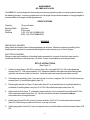
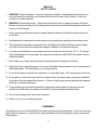
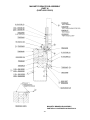
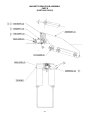
MAGNABEND
NO. MBB 4181 & 4182
ELECTROMAGNETIC BENDING BRAKE
OPERATIONS MANUAL & PARTS LIST
ROPER WHITNEY OF ROCKFORD, INC.
2833 HUFFMAN BLVD., ROCKFORD, ILLINOIS 61103-3990 * 815/962-3011 * FAX 815/962-2227
Website: www.roperwhitney.com * Email: [email protected]
MAGNABEND
NO. MBB 4181 & 4182
The MBB4181 is a bending brake that employs an electromagnetic system for clamping sheet metal for
the bending process. It comes complete with one full length and ten shorter keepers of varying lengths to
accommodate a full range of width requirements.
SPECIFICATIONS
Capacity
Bending Width
Weight
Electrical
18 ga. mild steel
49 inches
275 pounds
115V, 1PH, 60 HZ (MBB4181)
230V, 1PH, 60HZ (MBB4182)
WARNING
MECHANICAL DANGER:
Keep hands and fingers clear of clamping keepers at all times. Misuse or improper handling of the
bending brake may result in accidental pinching that could cause injury to or loss of fingers.
ELECTRICAL DANGER:
Misuse or improper installation of bending brake connected to a source of electricity may result in
accidental shock that could cause injury or death. Power cord installation must be grounded.
SET-UP INSTRUCTIONS
(See Figure 7)
1.
Attach four legs (Items 19 & 20) to column (Item 18), using eight 3/8-16 x 3/4 socket head cap
screws (Item 21). With approximately 5/16” clearance between the brake and the stiffening plate,
guide the two screws down into the slots. Level the brake sub-assembly and tighten screws.
2.
Set brake sub-assembly (Item 1) into slots in top of column, using two 3/8-16 x 3/4 socket head cap
screws (Item 21) and stiffening plate (Item 22).
3.
Place angle indicator rod (Item 12) and collar (Item 27) over handle (Item 8) and attach handle to
underside of bending beam, using two 5/16-18 x 5/8 socket head cap screws (Item 10).
4.
Attach anchor block (Item 13, attached to angle indicator rod) to magnetic base with two #10-24 x
5/8 socket head cap screws (Item 14). Be sure that brass actuator is assembled above
microswitch lever in magnetic base.
5.
Attach trays (Items 23 & 24) to rear of column with two 1/4-20 x 1/2 round head machine screws
(Item 25). Narrow tray is positioned to front, over top of column.
6.
Attach gauge bars (Item 26) to rear of magnetic base, and add collars and thumbscrews (Items 27 &
28).
-2-
MAGNABEND
NO. MBB 4181 & 4182
SET-UP INSTRUCTIONS
(Continued)
7.
Fasten legs securely to floor with appropriate screws, or use optional foot plate assembly.
8.
For Model MBB4181, connect power cord to 115 volt grounded outlet. For Model MBB4182, bring
230V, 1 phase, 60 HZ line to quick disconnect box mounted on rear of brake column.
9.
When required to move the assembled bending brake (275 lb. weight), proper lifting shall be with an
overhead or portable crane, and using a lifting sling placed securely about the magnet bending table
and stand.
Do not attempt to slide the bending brake across the floor, because tipping may result in accidental
damage to the brake, or cause personal injury.
OPERATING INSTRUCTIONS
STRAIGHT BENDING:
1.
Be sure main power is turned on, and the ball detents on the underside of the full length keeper are
properly located in the angled grooves in the magnetic base.
2.
Insert the workpiece under the keeper. Tilt the keeper forward and align your bend with its front
edge.
3.
Depress and hold the safety button to apply a light clamping force.
4.
Begin bending by lifting the handle. Full clamping will occur and the safety button can now be
released. Continue bending until the desired angle is reached. The angle gauge on the handle
indicates the angle between the bending beam and the magnetic base. The adjustable collar
provides a stop for repeat operations.
5.
Lower the handle to switch off the magnet and remove the workpiece.
LIP OR HEM:
1.
Proceed as with Straight Bending, but continue bend as far as bending beam will go (approximately
120°).
2.
Reposition the keeper and workpiece as shown in Figure 1.
Press the safety button and swing the beam over to partially
flatten the lip.
FIGURE 1
-3-
MAGNABEND
NO. MBB 4181 & 4182
OPERATING INSTRUCTIONS
(Continued)
3.
Fully flatten lip by using magnetic clamping only. Position workpiece
as shown in Figure 2. Press safety button and lift handle slightly.
4.
Lower handle and remove workpiece.
FIGURE 2
BOX BENDING:
1.
Starting with a notched blank, make the first two bends using the full
length keeper as in straight bending.
2.
Select one or more of the shorter keepers and position them as
shown in Figure 3. It is not necessary to make an exact length since
the bend will carry over up to 1” between keepers, depending on the
type and thickness of material being bent.
FIGURE 3
PARTIAL BENDS:
1.
The open end design of the MAGNABEND allows partial bending.
2.
Position the portion of the workpiece to be bent under a keeper
at the end of the magnetic base. Allow portion to be left flat to
extend beyond the end. (Figure 4)
3.
Proceed as with straight bending.
FIGURE 4
ROLLED EDGES:
1.
Rolled edges of various diameters may be formed, using
any mild steel round bar.
2.
Position the workpiece, keeper and bar as shown in Figure 5.
Be sure that keeper does not overlap front pole piece. Position
the leading edge of the workpiece as nearly under the center of
the bar as possible, to obtain a minimum flat section in the finished roll.
3.
Wrap the workpiece around the bar with the bending beam as in
straight bending. Reposition the workpiece as shown in Figure 6 and
continue to wrap until the desired roll is reached. The number of
wrapping operations will vary with the diameter of the bar and the
material being bent.
-4-
FIGURE 5
FIGURE 6
MBB 4181
SAFETY RULES
1.
WARNING: Electrical danger -- misuse or improper installation of bending brake connected to a
source of electricity may result in accidental shock that could cause injury or death. Power cord
installation must be grounded.
2.
WARNING: Mechanical danger -- keep hands and fingers clear of clamping keepers at all times.
Misuse or improper handling of the bending brake may result in accidental pinching that could cause
injury to or loss of fingers.
3.
Do not operate bending brake without reading Operator’s Manual and without proper supervisory
instructions.
4.
Bending brake is a one person machine and must be operated by qualified authorized personnel.
5.
The magnetic bending base is intended only for bending sheet metal through the keeper clamps.
Any other use may seriously damage the magnetic surfaces, or cause personal injury.
6.
For heavy duty bending, the mounting legs should be attached to the floor with 1/2” x 1 1/4” screws.
If the bending brake is to be portable, the optional foot platform kit #256080004 should be used for
additional stability.
7.
Do not place any foreign objects between clamping keeper and magnetic work base.
8.
When using short clamping keepers, do not store full-length clamping keeper on any structural part of
the bending brake. This also applies to any foreign objects.
9.
Do not clutter keeper tray with tools, bent parts, or scrap sheet metal. Only store keepers in the tray.
10. Do not place or hold any foreign steel bars or plates within the keeper area or attempt to reposition
any keeper while the magnet is switched on. Failure to comply may seriously damage the magnetic
surfaces or cause personal injury.
11. Proper handling procedures are required for large sheet metal lengths, as they may become
awkward to handle when the magnet is switched off (upon lowering the bending beam).
12. Do not use bending brake if servicing is required.
13. When not in use, turn off electrical power.
REMEMBER!
The shapes to be bent on MAGNABEND are really only limited by the imagination. As you become more
familiar with its operation, you will discover many possibilities beyond the capability of any conventional
bending brake.
-5-
NO. MBB 4181 & 4182
PARTS CHART
NO. MBB 4181 & 4182
PARTS LIST
ITEM
PART NO.
1
2
3
4
5
6
7
8
9
10
11
12
13
14
15
16
17
18
19
20
21
22
23
24
25
26
27
28
29
30
31*
256130003
Brake Sub Assembly, Magnetic
256080001
Hinge Assembly
756130447
Block, Hinge
756160470
Pin, Hinge
756260471
Wire, Retainer
756020442
Beam, Bending
756020443
Beam, Extension
756460445
Handle
633356335
Grip, Plastic
611012130
Screw, SHC 5/16-18 x 5/8
656000187
Scale, Angle
756030448
Rod, Angle Indicator
756130449
Block, Anchor
611012053
Screw, SHC #10-24 x 5/8
756030450
Actuator, Microswitch
656346146
Nameplate
656346147
Nameplate, Warning
756060451
Column
756140452
Leg, R.H.
756140453
Leg, L.H.
611012173
Screw, SHC 3/8-16 x 3/4
756060454
Plate, Stiffening
756440455
Tray, Front
756440456
Tray, Rear
609012086
Screw, RHM 1/4-20 x 1/2
756030444
Bar, Gauge
756260446
Collar
641012628
Screw, Thumb
256130002
Cover Assembly, Electrical
660082034
Switch, Safety
660152661 & 660152662 Isolator Switch & Heater
*(These two parts need to be ordered together)
256990048
Switch, Micro
256080005
Keeper, Full Length
756360432
Keeper, Half
756360433
Keeper, 4 3/4”
756360434
Keeper, 3 3/4”
756360435
Keeper, 2 3/4”
756360436
Keeper, 1 7/8”
756360437
Keeper, 1 3/8”
756360438
Keeper, 1”
756360439
Keeper, 3/4”
756360440
Keeper, 6”
756360441
Keeper, 12”
32
33
34
35
36
37
38
39
40
41
42
43
PART NAME
QTY.
-7-
1
3
3
3
3
1
1
1
1
2
1
1
1
2
1
1
1
1
2
2
10
1
1
1
1
2
3
3
1
1
1 ea.
1
1
1
1
1
1
1
1
1
1
1
1
MAGNETIC BRAKE SUB ASSEMBLY
(PART A)
(PART #256130003)
MAGNETIC BRAKE SUB ASSEMBLY
PARTS B & C CONTINUED ON PAGES 9-10.
-8-
MAGNETIC BRAKE SUB ASSEMBLY
PART B
(PART #256130003)
-9-
MAGNETIC BRAKE SUB ASSEMBLY NOTES
PART C
(PART #256130003)
1
Before connecting coil to rectifier, hi-pot test coil between steel parts and coil lead wires. There
shall be no current leakage with 1500 volts A.C. for 1 second; note that only two tests are
permissible per assembly.
2
Alum. cover strip must not extend above steel poles.
3
Micro switch shall be turned on within 3° beam movement when lifted from the down position.
Upon lowering the beam from the 90° position the micro switch shall turn off within 15° beam
movement. Adjustments made with noted part.
4
Noted handle is installed only for testing the brake and setting the angular scale. When moving
beam up to 180° and returning to 0° position there shall be no binding or beam misalignment
through hinges.
5
Noted surfaces free of blue paint. Remainder of brake paint blue #51-5-017.
6
Testing procedure:
A. Place full length keeper (painted) on the brake magnetic surface. With 115 volts A.C. switch
power on and check pilot light indication.
B. Press the safety button to apply light clamping. The keeper should pull down. If not, then
check for foreign matter under keeper, lifting detent sticking, excessive bow in keeper, non
flat magnetic surface, etc.
C. Turn on main magnetic field by pressing safety button and slightly pulling beam handle
beyond 3° movement. Measure the current draw. Should be 12 amps + 10% but will
decrease as coil heats up. Leave the current on until the thermal overload trips. That takes
1 to 3 minutes.
D. Make a full length bend with 18 gage mild steel and make sure keeper does not pop off and
bend is straight with a uniform bend angle. Bend radius shall not exceed 5/32”.
E. Fill out inspection sheet to be signed by foreman.
7
Noted parts must be assembled to hinge assembly before installing on bending brake.
8
Press pin flush with top surface of hinge plate. Grease pin nose.
9
Noted surfaces free of yellow paint. Remainder of keeper paint yellow #51-4-239.
10
Press flush with top surface of keeper.
11
Ensure that mating (spherical radius) surfaces of hinge block and pin are in firm contact
throughout entire travel. If necessary flatten spring with punch.
- 10 -
MAGNABEND ELECTRICAL SCHEMATIC