1
OWNER'S
MANUAL
MODEL NO.
580.327140
RAFTSMAN°
PORTABLIE GENERATOR,
CUSTOMER
HELPLINIE
120-240 VOLT/4200 WATT
12-VOLT D-C BATTERY CHARGER
DELUXE PORTABLE GENERATOR
HOURS:
Mon.-
Frl. 8 a.m. to 5 p.m
•
Assembly
•
Operation
CAUTION:
Read and Follow
•
Customer Responsibilities
ell Safety Rules
end Instructions
•
Service and Adjustment
Before Operating
This Equipment
•
Repair Parts
(CST)
SEARS,
PanNo. B2552
ROEBUCK
Rev-I (3/27/98)
and
CO.,
Hoffman Estates,
IL
60179
U.S.A.
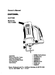
CRAFTSMAN°
OWNER'S
MANUAL
120/240 VOLTS / 4200 WATT A-C
12 VOLTS D-C BATTERY CHARGER
DELUXE PORTABLE GENERATOR
MODEL No.
580.32714O
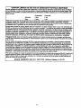
Each Portable Generator has its own model number. Each engine has its
own part number.
The model number for your Portable Generator will be found on a decal
attached to the unit.
IF YOU NEED
REPAIR SERVICE
The part number for your engine will be found on the Blower Housing of
the engine adjacent to the spark plug.
All parts listed herein may be ordered through Seam, Roebuck and Co.
Service Centers and most Retail Stores.
OR PARTS
WHEN ORDERING REPAIR
LOWING INFORMATION:
FOR REPAIR SERVICE CALL
THIS TOLL FREE NUMBER
PARTS, ALWAYS
•
PRODUCT--
PORTABLE
•
MODEL NUMBER--580.327140
•
PART NUMBER
•
PART DESCRIPTION
GIVE THE FOL-
GENERATOR
1"800"4" REPAIR
(1-800-473-7247)
FOR REPLACEMENT PARTS INFORMATION AND ORDERING,
CALL THIS TOLL FREE NUMBER:
1-800-FON-PART
(1-800-366-7278)
Your Sears merchandise has added value when you consider that Sears
has service units nationwide staffed with Sears trained technicians....professional technicians specifically trained on Sears products, having the
)arts, tools and the equipment to ensure that we meet our pledge to you,
we service what we sell.
SEARS ROEBUCK and CO., Hoffman Estates, IL 60179 U.S.A.
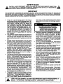
SAFETY RULES
CAUTION: ALWAYS DISCONNECT SPARK PLUG WIRE AND PLACE WIRE WHERE IT CANNOT CONTACT SPARK PLUG, TO PREVENT ACCIDENTAL STARTING WHEN SET'rING UP, TRANSPORTING,
ADJUSTING OR MAKING REPAIRS TO YOUR GENERATOR.
IMPORTANT
THIS GENERATOR IS DESIGNED FOR OUTDOOR USE ONLY. USING THIS GENERATOR INSIDE ANY BUILDING OR
ENCLOSURE INCLUDING THE GENERATOR COMPARTMENT OF A RECREATIONAL VEHICLE (RV), IS DANGEROUS.
FIRE OR AN EXPLOSION MAY RESULT. NO USER PERFORMED MOD F CAT ONS, NCLUD NG VENTING OF EXHAUST
AND/OR COOLING VENTILATION, WILL ELIMINATE THE DANGER.
•
If this unit is used for backup power in the event of
a utility power failura, take the followingsteps: BEFORECONNECTING
THE GENERATOR TO AN
ELECTRICAL SYSTEM OPEN THE MAIN CIRCUIT BREAKER OR MAIN SWITCH SERVING
THE SYSTEM TO ISOLATE THE GENERATOR
SYSTEM FROM THE ELECTRIC UTILITY. FAILURE TO ISOLATE THE GENERATOR AND UTILITY SYSTEMS MAY RESULT IN DAMAGE TO
THE GENERATOR AND MAY ALSO RESULT IN
INJURY OR DEATH TO ELECTRIC
UTILITY
WORKERS DUE TO BACKFEED OF ELECTRICAL ENERGY.
•
This generator supplies dangerously high electrical
voltages. Use care to prevent extremely hazardous
and possibly lethal electrical shock. Never permit
any unqualified person(s) to operate or service the
unit.
•
DO NOT operate this equipment in the rain, while
standing in water, while barefoot, or while hands or
feet are wet. Dangerous electrical shock will result.
The spark arrestor muffler can become extremely
hot. DO NOT operate this equipment in areas where
combustible material such as grass, leaves or paper
products can come in contact with the muffler.
Maintain all wiring, extension cords, etc., in good
condition. Worn, bare, frayed, or otherwise damaged wiring and cord sets may cause dangerous
electrical shock and may also result in damage to
equipment and/or property.
The National Electrical Code requires that the generator be properly connected to an approved earth
ground. Local electrical codes may also require
proper grounding of the unit. See ASSEMBLY section for mere grounding information.
Wire gauge sizes of wiring and cord sets must be
large enough to handle the maximum electrical load
to which they will be subjected. Most devices require cord sets rated 125 AC volts at 20 to 30
amperes or 250 AC volts at 20 amps (or greater).
Some devices may require a higher or lower rating.
Refer to the Owner's manual of the electrical device
for the manufacturer's recommendations.
Cord
sets that are too small in diameter or too long will
overheat, become damaged and may cause property damage and/or electrical shock.
The generator engine consumes oxygen and gives
off DEADLY carbon monoxide gas through its exhaust system. This dangerous gas if breathed in
surf c ent concentrations, can cause unconsciousness or even death. Operate this equipment out-
•
•
•
•
•
doors only, in well ventilated areas where exhaust
gases cannot accumulate and endanger people or
animals.
•
•
•
•
•
•
•
•
•
Gasoline is extremely FLAMMABLE and its vapors
are EXPLOSIVE.
Comply with all laws regulating
the storage and handling of gasoline. DO NOT
permit smoking, open flames, sparks or heat in the
vicinity while handling gasoline.
Avoid spilling
gasoline on a hot engine. DO NOT fill fuel tank:
while engine is running or hot. Clean off any spilled
gasoline before starting engine.
DO NOT fill fuel tank completely full. Allow room at
top of tank for fuel expansion or fuel may expand
and overflow onto a hot engine.
Drain all gasoline from tank before transporting your
generator inside your car or other vehicle.
DO NOT store the generator with fuel in tank where
gasoline vapors might reach an open flame, spark,
or pilot light, as on a fumace, water.heater, dryer,
etc. FIRE or an EXPLOSION might result.
DO NOT insert any object or tool through cooling air
slots or openings of the engine or generator, even
if the eng=ne is not running. Damage to the unit or
personal injury may result.
DO NOT attempt to change the engine govemed
speed.. Factory settings are correct when you racalve the unit. Excessively high engine speeds may
result in injury or damage to equipment.
DO NOT use the unit if it has been damaged. Repair
or replace all damaged or defective components
before you run the unit.
DO NOT permit children to operate or service the
generator.
Read your Owner's Manual carefully. Only persons
who are familiar with these safety rules and have
been properly instructed in the use of this product
should be permitted to use the product.
LOOK FOR THIS SYMBOL TO POINT OUT IMPORTANT
SAFETY PRECAUTIONS.
MEANS
"ATTENTIONII!
BECOME
ALERTI!!
YOUR SAFETY IS INVOLVED."
IT
I
I
CONGRATULATIONS
on your pumheae of a Sears Craftsman Generator. It has been designed, engineered and
manufactured to give you the best possible dependability
and performance.
Should you experience any problem you cannot easily
remedy, please contact your nearest Sears Service Center/Department or call the 1-800 number listed on the front
of this manual. We have competent, well-trained technicians and the proper tools to service or repair this unit.
Please read and retain this manual The instructions will
enable you to assemble and maintain your generator properly, Always observe the 'SAFETY RULES."
PRODUCT SPECIFICATIONS
Generator
Specifications
RATED MAXIMUM
POWER
4200 Watts (4.2 kW)
RATED VOLTAGE
120/240 Volts a-c
RATED MAXIMUM
LOAD CURRENT
35/17.5 a-c amperes
RATED FREQUENCY
60 Hz at 3600 rpm
PHASE
Single Phase
BA'I-FERY CHARGE
MODEL
NUMBER
Amps:
Volts:
10 DC Amps
12 volts DC
580.327140
Engine Specifications
SERIAL
NUMBER
DATE OF
PURCHASE.
RATED HORSEPOWER
7.8 at 3600 rpm
DISPLACEMENT
220cc
SPARK PLUG: Type:
Champion RC12YC or
or equivalent
0.030 inch !0.76ram)
Set Gap to:
THE MODEL AND SERIAL NUMBERS
WILL BE
FOUND ON A DECAL A'I-T'ACHED TO THE GENERATOR STATOR CAN.
YOU SHOULD RECORD BOTH SERIAL NUMBER
AND DATE OF PURCHASE AND KEEP IN A SAFE
PLACE FOR FUTURE REFERENCE.
GASOLINE CAPACITY
4 U.S. gallons
OIL (620ml)
SAE 30 Oil
SAAE10W- 30)
E 5W-20 or 5W-30
summer
winter
MAINTENANCE
AGREEMENT
A Sears Maintenance Agreement is available on this product, Contact your nearest Sears store for details.
CUSTOMER
NOTE: Your generator is equipped with a spark arrestor
muffler. The spark arrestor must be maintained in effective
working order by the owner/operator.
In the State of California a spark arrestor is required by law
(Section 4442 of the California Public Resources Code).
Other states may have similar laws. Federal laws apply on
federal lands.
RESPONSIBILITIES
•
Read and observe the safety rules.
•
Follow regular schedule inmaintaining, caring for and
using your generator,
•
Followtheinstructionsunder'Maintenance"and
age" sections of this Owner's Manual.
"Stor-
TABLE OF CONTENTS
SAFETY RULES ..................................
MAINTENANCE
PRODUCT
CONTENTS
AGREEMENT
SPECIFICATIONS
OF HARDWARE
INSIDE COVER
RECOMMENDATIONS.
.............................
1
SERVICE
.......................................
1
STORAGE
3
TROUBLESHOOTING
3
WIRING DIAGRAM .........................................
.....................
......................................
MAINTENANCE
AND ADJUSTMENTS
...................................
ASSEMBLY ..........................................
OPERATION
SERVICE
.......................................
4-8
9-10
11
..................
12
....................................................................
12
POINTS ......................
13
14
REPAIR PARTS .......................................................
16-21
WARRANTY
22-24
............................................................
PARTS ORDERING. ....................
BACK COVER
Index
-AAir Cleaner... .........
Assembly ................
-R-
-H4, 10
3
Head boils ..............
11
Receptacles ..............
Retorque head bolts .......
3
11
-I-
-BBefore Starting ............
Battery Charging ...........
Battery Safety .............
Idle Control ...............
5
7
6
6
-LLow Oil Shutdown ..........
8
Lubrication ..............
-CCarburetor. ..............
Circuit Breakers ..........
Cord Sets ................
Customer Responsibilites ....
--M-11
3,5
3
1
-EEngine
Carburetoradjustment ........
5,9
11
Ot/level ....................
11
Speed
.....................
11
Electrical Loads ...........
8
Maintenance
Agreement ..................
Cleaning generator............
Engine maintenance...........
General Recommendations.....
Generator Maintenance ........
-O9
Operation ...............
4-8
8
-p-
Gasoline .................
5
Grounding Lug ............
3
Parts, repair ...........
2
Safety Rules ......
inside cover
Service and Adjustments...
11
Service Recommendations . 12
Specifications .............
Starting Engine ............
Stopping Engine ...........
Storage .................
1
5
6
12
-TTroubleshooting ..........
13
-W-
OilLevel .................
Overloading ..............
-G-
1
9
9
9
9
-S-
16-21
Warranty ..............
22-24
Wattage Reference Guide...
Widng Diagram ...........
8
14
ASSEMBLY
Your AC generator was completely assembled at the factory. It is ready for use after it has been propedy serviced
with the recommended lubricating oil and fuel.
R.,RCI--I/_ED
3NtlRE COI_
IF YOU HAVE ANY PROBLEMS WITH THE ASSEMBLY
OF YOUR GENERATOR, PLEASE CALL THE GENERATOR HELPLINE AT 1-800-222-3136.
IMPORTANT: ANY ATTEMPT TO RUN THE ENGINE
BEFORE IT HAS BEEN SERVICED WITH THE RECOMMENDED OIL WILL RESULT IN AN ENGINE FAILURE.
TO REMOVE
GENERATOR
FROM
Set the carton on a flat rigid surface with 'qHIS SIDE
UP" arrows pointing upward.
•
•
Carefully open the top flaps of shipping carton.
Cut down corners at one end of shipping carton and
lay that side of carton down flat.
•
Remove packing material, carton fillers, etc.
•
Remove generator from shipping carton.
SHIPPED
LOOSE
WITH
;
; i:i
,
N_JIWAL(N)
GROUND(G)
CARTON
•
PARTS
120 V_3
FIG. 2
_vd
Set
UNIT
•
•
Battery Charge Cables
Spark Plug Wrench and Screw Driver
•
•
EngineOil
Wheel Kit
F)Tc-_d
(c-re_)
FIG. 3
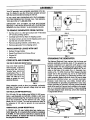
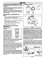
GROUNDING THE GENERATOR
CORD SETS AND CONNECTOR PLUGS
120 VOLTS DUPLEX RECEPTACLE
Use only high quality,
!
well-insulated, extension i
cords with the 120-volt
"duplex"type
electrical
receptacles (Fig. 1). All
cord sets used should be
rated 125 volts at 15 a-c
amps or greater for most
electrical devices.
FIG. 1
Keep extension cords as short as possible, preferably
less than 15 feet long to prevent voltage drop and wires
from overheating.
120 VOLTS, 30 AMP RECEPTACLE
The National Electrical Code requires that the frame and
external electrically conductive parts of this generator be
properly connected to an approved earth ground. Local
electrical codes may also require proper grounding of the
unit. For that purpose, a GROUNDING WING NUT is provided on the base of the cradle (Fig. 4). Generally, connecting a No. 12 AWG (American Wire Gauge) stranded
copper wire to the grounding lug and to an earth-driven
copper or brass grounding rod (electrode) provides adequate protection against electrical shock. Be sure to keep
ground wire attached when you connect electrode.
However, local codes may vary widely. Consult with a
local electrician for grounding requirements in your area.
Proper grounding of generator will help prevent electricel
shock in the event of a ground fault condition in the generator or in connected electrical devices. Proper grounding
also helps dissipate static electricity, which often builds up
in ungrounded devices.
For 120 volts, 30 amp locking type NEMA L5-30R receptacle, a well-insulated cord set with a NEMA L5-30P locking type connector plug (Fig. 2) must be properly connected to the receptacle and the desired 120 volts, single
phase, 60 Hz, a-c load. The cord set should be rated 30
a-c amperes at 125 volts (or greater) for most electrical
devices.
#12 AWG STRANDED
COPPER WIRE
120/240 VOLTS, 20 AMP RECEPTACLE
A 120/240 volts, 20 amp, locking type type mating connector plug (Rg. 3) is required when using this receptacle
(L14-2OR). A 4-wire cord set, rated 20 a-c amperes at 250
volts (or greater), is required and must be connected to
the plug and to the desired loads.
3
GROUNO4NGROD
FIG. 4
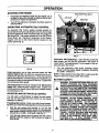
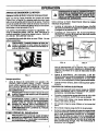
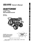
OPERATION
KNOW
YOUR
GENERATOR
READ THIS OWNER'S MANUAL AND SAFETY RULES BEFORE OPERATING YOUR GENERATOR. Compare the
illustrationswith your generator, to familiarize yourself with the locationsof variouscontrolsand adjustments. Save the
manualfor future reference.
FUELTANK
120-VOLTA.C.
30 AMP RECEPTACLE
120-VOLTA.C.
DUPLEXRECEPTACLE
120/240-VOLT
A.C.
20 AMP RECEPTACLE
AIR CLEANER
IDLECONTROLSWlTCl
RECOILSTARTER
12-VOLTD.C.
RECEPTACLE
CIRCUITBREAKERS
120-VOLT A.C. "DUPLEX" RECEPTACLES
-- May be
used to supply electrical Ix}wer for the operation of 120 volts
at 15 amps A.C., single phase, 60 Hz, AC electrical lighting,
appliance, tool and motor loads.
120-VOLT A.C., 30 AMP RECEPTACLE -- May be used
to supply electrical power for the operation of 120 volts at
30 amps A.C, single phase, 60 Hz, A.C. electrical lighting,
appliance, tool and motor loads.
120/240-VOLT A.C., 20 AMP RECEPTACLE -- May be
used to supply electrical power for the operation of 120
and/or 240 volts at 20 amps A.C., single phase, 60 Hz, AC
electrical lighting, appliance, tool and motor loads.
RECOIL STARTER
GN engine.
--
(not shown) Used for starting the
RUN/STOP SWITCH -- (not shown) Set this switch to
=RUN" before using recoil starter. Set switch to "STOP" to
switch OFF engine. Located on engine block.
IDLE CONTROL SWITCH -- With this switch set to ON,
printed circuit board in control panel automatically reduces
engine speed when no load is connected and increases
engine to proper speed when load is applied. However, be
sure switch is OFF when starting engine.
CIRCUIT BREAKERS (A.C.) -- Each receptacle is provided with a circuit breaker to protect the generator against
electrical overload. Breakers are =push to reset" type.
SPARK ARRESTOR
MUFFLER -- Exhaust muffler lowers
engine noise and is equipped with a spark arrestor screen.
AIR CLEANER -- Uses a dry type filter element and foam
pre-cleaner to limit the amount of dirt and dust that gets in
the engine.
FUEL TANK --Capacity
CHOKE SWITCH
of four U.S. gallons (15.2 liters).
-- Used when starting a cold engine.
12-VOLT D.C. RECEPTACLE -- Recharge a discharged
12 voltsautomotivetype batterythrough this receptacle.
4
OPERATION
IF YOU HAVE ANY PROBLEMS
GENERATOR,
PLEASE
CALL
HELPLINE AT 1-800-222-3136.
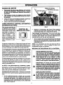
BEFORE STARTING
OPERATING YOUR
THE GENERATOR
•
Locate the Idle Control On/Off switch on control panel
and set it to OFF position.
•
Locate the Run/Stop switch (Fig. 6) next to the engine
cylinder head and set it to RUN.
ENGINE
\
ADD OIL:
Place generator on a level surface and remove one of
.the y..ellowOil .FillCaps (Rg. 5) and add engine oil unti!
levm is at point owovernowmg. Check engine oil levee
before starting each time thereafter. If oil level is below
point of overflowing, fill to proper level. The recommended oils include (during summer months) SAE 30
oil. SAE 10W-30 is an acceptable substitute. During
winter months use SAE 5W-20 or 5W-30. DO NOT
USE lOW-40. Crankcase oil capacity is about 720ml
with oil filter.
CAUTION: ANY AI"rEMPT TO CRANK OR START
THE ENGINE BEFORE IT HAS BEEN PROPERLY
SERVICED WITH THE RECOMMENDED OIL RESULTS IN AN ENGINE FAILURE.
FIG. 6
•
Close the choke to FULL position (Fig. 7) by sliding it
to far position in direction indicated by arrow on air
cleaner housing.
FULL
RUN
FIG. 5
ADD GASOLINE:
•
Use regular UNLEADED gasoline with the generator
engine. Regular leaded gasoline may also be used if
UNLEADED is not available. Fuel tank capacity is 4
U.S. gallons.
_1=
CAUTION:
DO NOT
OVERFILL
THEEXPANSION.
FUEL TANK.
ALWAYS ALLOW
ROOM
FOR FUEL
WARNING:
THE
CAUTION:
ENGINE
NEVER START, OR STOP, THE EN-
GINE-GENERATOR WITH ELECTRICAL LOADS
CONNECTED TO THE RECEPTACLES WITH THE
CONNECTED DEVICES TURNED ON.
•
•
•
Grasp the starter grip and pull slowly until you feel
resistance. Then pull rapidly. Repeatif necessarywith
choke opened slightly.
•
When engine starts, open choke gradually.
CONNECTING
Start, store and fuel the unit in a level position.
Open fuel shut-off valve.
ELECTRICAL
LOADS
•
Let engine stabilize and warm up for about five minutes
after starting.
•
Plug in and turn on the desired 120 or 240 volts, single
phase, 60 Hertz, a-c electrical loads.
•
DO NOT connect 240 volts to 120 volts duplex receptacles.
•
DO NOT connect 3-phase loads to panel receptacles.
•
DO NOT connect any 50 Hz loads to the generator.
•
Add up the rated watts of all lights tool appliance and
motor loads you are powering at one time. This total
should NOT be greater than (a) generator's rated wattage. capac!_ or (b) circuit breaker rating of the receptac=e suoplymg the power.
NEVER FILL FUEL TANK INDOORS.
NEVER RLL FUEL TANK WHEN ENGINE IS RUNNING OR HOT. DO NOT UGHT A CIGARET OR
SMOKE WHEN FILUNG FUEL TANK.
TO START
FIG. 7
OPERATION
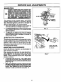
STOPPING
•
•
THE ENGINE
IDLE CONTROL
Disconnect all electrical loads and let engine run at
no-load for about five minutes to stablize internal tomperatures of engine and generator.
BOLT
JAM NUT
BRACKET
Tum off the engine by moving the Run/Stop switch to
STOP position.
OPERATING
AUTOMATIC
IDLE CONTROL
An Automatic Idle Control system provides greatly improved fuel economy by operating the unit at its normal high
govemed speed only when electrical loads are plugged in
and tumed ON. The system consists of (a) an Idle Control
Circuit Board, (b) a Sensing Transformer, (c) an Electromagnet, and (d) an Idle Control Switch located on the
control panel (Fig. 8).
IDLE
CONTROL
FIG.9
Carburetor "Microadjusting":
Once the idle control has
been preset, you can use the carburetor's idle screw to
make further =microadjustments"
to the speed of the angine-generator idle control.
•
FIG. 8
Engine-generator runs at high governed speed with Idle
Control Switch ON only when an electrical load is connected to the generator and turned on. When the electrical
load is disconnected, an Electromagnet is energized to pull
the engine throttle control against its idle stop. Engine then
runs at reduced (idle) speed.
NOTE: Engine speeds of less than 38 Hz. could cause the
engine to stall if you apply sudden block loads.
BA'I-rERY SAFETY
The Electromagnet cannot be energized with Idle Control
Switch OFF, since its power circuit is open. Engine runs
at high govemed speed (about 3600 rpm) whether load(s)
are connected or not.
ADJUSTING
A
AND SETTING IDLE CONTROL
You will need a volt-ohmmeter to adjust the idle control.
You can set and adjust the Idle Control on the Deluxe
Generator as follows:
With the unit running and warmed up, tum the idle
control bolt clockwise (faster speed), or counterclockwise (slower speed) until the engine speed is between
25 and 35 Hz. (1500 - 2100 rpm). See Fig. 9.
•
Lock the Idle Control Jam nut against the idle control
bracket, while the engine is still running at a range of
25 to 35 Hz.
WARNING: STORAGE BAI"rERIES GIVE OFF EXPLOSIVE HYDROGEN GAS WHILE CHARGING.
AN EXPLOSWE MIXTURE WILL REMAIN AROUND
BATTERY FOR A LONG 11MEAFTER IT HAS BEEN
CHARGED. THE SUGHTESTSPARK CAN IGNITE
GAS AND CAUSE AN EXPLOSION. SUCH AN EXPLOSION CAN SHATTER BATTERY AND CAUSE
BLINDNESS OR OTHER SERIOUS INJURY.
WARNING: DO NOT PERMIT SMOKING, OPEN
FLAME, SPARKS OR ANY OTHER SOURCE OF
HEAT AROUND A BAI"rERY.
DO NOT USE A
UGHTER OR OTHER FLAME FOR CHECKING
BATfERY FLUID LEVELS. WEAR PROTECTIVE
Presetting Idle Control: Refer to the Idle Control Assembly when you make the initial adjustment oi the idle Control.
•
Turn the carburetor's
idle screw clockwise (faster
_4Oez
ed ) until the engine speed is between 38 and 40
(2280 - 2400 rpm).
GOGGLES,
RUBBER
APRON
AND
RUBBER
GLOVES WHEN
WORKING
AROUND
A BATrERY.
BATTERY ELECTROLYTE
FLUID IS AN EXTREMELY CAUSTIC SULFURIC ACID SOLUTION
THAT CAN CAUSE SEVERE BURNS. DO NOT
PERMIT FLUID CONTACT WITH EYES, SKIN,
CLOTHING, ETC.
IF SPILL OCCURS, FLUSH
AREA WITH CLEAR WATER IMMEDIATELY.
6
OPERATION
CHARGING
Connectbattery charge cable clamp with red handle to
A BA1TERY
battery post or terminal indicated by a POSITIVE,
or(*).
Your generator has the capability of recharging a discharged, 12-volt automotive or utility style storage battery.
Do not use the unit to charge any 6-volt batteries. Do not
use the unit to crank an engine having a discharged battery.
To recharge 12-volt battedas, proceed as follows:
•
Check fluid level in all battery cells. If necessary, add
ONLY distilled water to sever separators in battery
cells. DO NOT USE TAP WATER.
•
If the battery is equipped with vent caps, make sure
they are installed and are tight.
•
If necessary, clean battery posts or terminals.
•
Connect battery charge cable connector plug to panel
recaptacle (Fig. 10). identified by the words =12-VOLT
D.C.
POS
•
Connect battery charge cable clamp with black handle
to battery post or terminal indicated by a NEGATIVE,
NEG, or (--).
.
Start en.g=ne(see =Starting the Engine" on Page 5). Let
the engine run while battery recharges.
•
When battery has charged, shut down engine (see
=Stopping the Engine" on this page).
NOTE: Use an automotive hydrometer to test battery state of
charge and condition. Follow the hydrometer manufacturer's
instruc_onscarefully Generally, a battery is considered to be at
100% state of charge when speQtic gravityof its flu_ (as measured by hydrometer)is 1 260.
LOW OIL PRESSURE
SHUTDOWN
SYSTEM
The engine is equipped w_tha low od pressure sensor that
shuts down the engine automatically when the oil pressure
drops below 6 psi. If the engine shuts down by itself and
the fuel tank has enough gasoline, check engine oil level.
INITIAL STARTUP
A delay built m the shutdown system allows oil pressure to
build dunng starting. The delay allows the engine to run for
about 10 seconds before sensing oil pressure.
SENSING LOW PRESSURE
If the system senses low oil pressure during operation, the
eng=ne shuts down. As the system shuts down, the low oil
light comes ON. However, once the engine has stopped
rotating, this light will go OFF.
RESTARTING
If you try to restart the eng=ne within 5 seconds after it shuts
down, the engine may NOT start. The system needs 5 to
10 seconds to reset.
FIG. 10
If you do restart the engine after such a shutdown and
have not corrected the low oil pressure, the engine
runs for about 10 seconds as described above and then
stops.
7
OPERATION
DON'T OVERLOAD
Some electric motors, such as induction types, require
about two-and-a-half times more watts of power for
s_rtin_ than for running. This surge of power lasts for
omy a few seconds when starting such motors. Be sure
you allow ;or this high starting wattage when selecting
electrical devices to connect to your generator.
First
figure the watts needed to start largest motor. Add to
that figure running watts of all other connected loads.
THE GENERATOR
Overloading a generator in excess of its rated wattage
capacity can result in damage to generator and to connected electrical devices. Observe the following, to prevent overloading the unit:
•
Add up the total wattage of all electrical devices to be
connected at one time. This total should NOT be
greater than the generator's wattage capacity.
•
The rated wattage of lights can be taken from light
bulbs. The rated wattage of tools, appliances and
motors can usual!y be found on a data plate or decal
affixed to the device.
•
If the appliance, tool or motor does not give wattage,
mulitply !20 volts Umas ampere rating to detarmnne
watts (volts x amps = watts).
WATTAGE
The GUIDE below is provided to assist you in determining how many items your generator can operate at
one time.
REFERENCE
GUIDE
RUNNING
RUNNING
WA'I-rS
WATTS
*Air Conditioner (12,000 Btu) ....................................
1700
Impact Wrench ...........................................................
Battery Charger (20 amp) ..........................................
500
*Jet Pump ...................................................................
800
Belt Sander (3") .........................................................
1000
Lawn Mower ..............................................................
1200
Chain Saw .................................................................
1200
Microwave Oven .........................................................
700
*Milk Cooler ...............................................................
1100
Cimular Saw (6-12/') .....................................
800 to 1000
500
Coffee Maker .............................................................
1000
Oil Burner on Fumaca ................................................
300
"Compressor (1 HP) ..................................................
2000
Oil Fired Space Heater (140,000 Btu) ........................
400
*Compressor (3/4 HP) ...............................................
1800
Oil Fired Space Heater (85,000 Btu) ..........................
225
*Compressor (1/2 HP) ...............................................
1400
Oil Fired Space Heater (30,000 Btu) ..........................
150
Curling Iron ................. ................................................
700
*Paint Sprayer, Airless (1/3 HP) .................................
600
"Deep Freeze .............................................................
500
Paint Sprayer, Aidess (handhelu) ...............................
150
Disc Sander (9") ........................................................
1200
Edge Trimmer .............................................................
500
"Refrigerator ...............................................................
600
Electric Nail Gun .......................................................
1200
Slow Cooker ...............................................................
200
Electric Range (one element) ....................................
1500
*Submersible Pump (1-1/2 HP) .................................
2800
Electdc Skillet. ..........................................................
1250
*Submersible Pump (1 HP) .......................................
2000
*Furnace Fan (1/3 HP) ..............................................
1200
*Submersible Pump (1/2 HP) ....................................
1500
Hair Dryer ..................................................................
1200
Sump Pump ................................................................
Hand Drill (1") ............................................................
1100
*Table Saw (10") .........................................
Television ........................................................
Hand Drill (1/2') ............................................
Radio ................................................................
750 to 1000
50 to 200
600
1750 to 2000
.200 to 500
Hand Drill (3/8") ..........................................................
500
Weed Trimmer ............................................................
Hand Ddll (1/4') ...........................................................
250
Hedge Trimmer ..........................................................
450
* Allow 2-1/2 times the listed watts for starting these
devices.
8
500
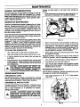
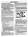
MAINTENANCE
GENERAL
Change oil while engine is still warm from running, as
follows:
RECOMMENDATIONS
The Owner/Operator is responsible for making sure that all
periodic maintenance tasks are completed on a timely
basis; that all discrepancies are corrected; and that the unit
is kept ctean and property stored. Never operate a damaged or defective generator.
GENERATOR
•
Clean area around oil drain plug, remove plug (Fig. 11)
and drain oil completely into a suitable container.
MAINTENANCE
Generator maintenance consists of keeping the unit clean
and dry. Operate and store the unit in a clean dry enviorment where it will not be exposed to exceesive dust, dirt,
moisture or any corrosive vapors. Cooling air slots in the
generator must not become dogged with snow, leaves or
any other foreign material.
OIL FILTER
I
Check the cleenliness of the generator fraquentiy and clean
when dust, dirt, oil, moisture or other foreign substances
are visible on its exterior surface.
A
NOTE: We DO NOT recommend using a garden hose to clean
the generator. Water can enter the engine fuel system and cause
problems. In addition, if water entem the generator through
coolingair slots,some of the water will be retained in voids and
cracks of the rotor and stator winding insulation. Water and dirt
buildup on the generator internal windings will eventually decrease the insulationresistanceof these windings.
FIG. 11
•
When oil has drained, install and tighten oil drain plug.
•
Remove oil fill plug and insert a clean fill funnel into
plug opening.
Fill engine crankcase with recommended oil until oil level is at point of overflowing. Do
not overfill above the point of overflowing. About 21
ounces (620ml) is required. POUR SLOWLY.
•
When engine crankcase is filled to proper level. Install
and tighten oil fill plug.
TO CLEAN THE GENERATOR:
•
Use a damp cloth to wipe exterior surfaces clean.
•
Use a soft, bristle brush to loosen caked on dirt, oil, etc.
•
A vacuum cleaner may be used to pick up loose dirt
and debris.
Replace Oil Filter: Replace the engine oil filter after first
8 hours of operation, every 50 operating hours thereafter.
Low pressure air (not to exceed 25 psi) may be used
to blow away dirt. Inspect cooling air slots and opening
on the generator. These openings must be kept clean
and unobstructed.
CAUTION:
NEVER INSERT ANY OBJECT OR
TOOL THROUGH THE AIR COOLING SLOTS, EVEN
IF THE ENGINE IS NOT RUNNING. DAMAGE TO
THE UNIT OR PERSONAL INJURY MAY RESULT.
•
Coat gasket of new filter with engine oil.
•
Turn the new filter clockwise until its gasket contacts
tightly with the filter adaptor. Then tighten by hand an
additional 3/4 to one turn.
HEAD BOLTS
After 50 hours of operation, retorque the head bolts for the
GN engine to 4.0 kg/m (29 foot-pounds).
OIL LEVEL
•
See OPERATION sectionon Page 4 for informationon checking
oil level. Oil level should be checked before each use or at least
every eight hours of operation. Keep oil level maintained.
CHANGING
Turn oil filter counterclockwise to remove (Figure 11).
RETORQUE
ENGINE MAINTENANCE
CHECKING
•
The torque sequence is A, B, C, D, E (star pattern).
See Fig 12.
O
B
OIL AND OIL FILTER
Change oil after first 8 hours of operation. Change oil every
50 hours thereafter. If you are using your generator under
dirty or dusty conditions, or in extremely hot weather,
change oil more often.
J ,_
FROM SPARK PLUG AND KEEP IT AWAY FROM
SPARK PLUG. DO THIS EVERYTIME YOU PERFORM ANY MAINTENANCE
ON THE PLUG
ENGINE
OR
CAUTION:
DISCONNECT SPARK
WIRE
THE GENERATOR,
E
C
FIG. 12
9
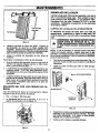
MAINTENANCE
SERVICE
AIR CLEANER
REPLACE
Your engine will not run properly and may be damaged if
you run it using a dirty air cleaner.
SPARK
PLUG
Change the spark plug every 100 hours of operation or
once each year, whichever comes first. This will help your
engine to start easier and run better. Replace with Champion RC12YC or equivalent type spark plug. Set spark plug
gap (Fig. 14) 0.030 inch (0.76mm).
Clean or replace the air cleaner paper filter (Fig. 13) once
every 25 hours of operation or once a year, whichever
comes first. Clean or replace mere often if operating under
dusty or dirty conditions. Clean foam pre-filter every 25
hours of operation or sooner under dusty conditions.
/
"_.030"
FEELER GAUGE
/_
A
I
(0.76mm)
COMPLETE AIR CLEANER SYSTEM INSTALLED
ON THE ENGINE. THIS COULD RESULT IN PRECAUTION: NEVER RUN THIS UNIT WITHOUT THE
MATURE WEAR TO THE ENGINE.
FIG. 14
CLEAN SPARK ARRESTOR
SCREEN
The engine exhaust muffler has a spark arrestor screen.
Inspect and clean the screen every 100 hours of operation
or once each year, whichever comes first.
p
PRECLEANER
PAPER FILTER
A
WORKING ON IT. CONTACT WITH A HOT MUFWARNING: LET THE MUFFLER COOL BEFORE I
FLER OR ENGINE CAN CAUSE SEVERE BURNS.
NOTE: If you use your generator on any forest-covered, brush°
covered or grass-coveredunimprovedland, it must have a spark
arrestor. The spark arrestormustbe maintainedin goodcondition
by the owner/operator.
FIG. 13
•
Clean and inspect the spark arrestor as follows:
•
To remove the heat shield from the muffler (Fig. 15),
remove the nine screws that connect the shield to the
muffler.
To clean or replace foam pre-filter:
MUFFLER
*
Remove air cleaner cover, then foam pre-tilter.
•
Wash pre-filter in soap water. Squeeze pre-c eaner dry
in clean cloth (DO NOTTWlST).
Saturata pre-c eaner
in clean engine oil and then wrap pre-ti tern clean dry
cloth to squeeze out excess oil (DO NOT TWIST).
•
SPARK ARRESTOR
SCREEN
Clean air cleaner cover before installing it.
To clean or replace paper air filter:
•
Remove air cleaner cover; then remove foam pre-fi ter
Iservice if necessary) and remove paper tilter.
,
Clean air filter by tapping it gently on a solid surface. If
the filter is too durty replace it with a new one. D spose
of the o d f Iter properly.
b
Clean air cleaner cover then insert pre-filter into cover.
Next insert new paper filter into cover to hod pre-filter
in place and assemble all of them to the base of the air
cleaner.
Heat Shield
FIG. 15
Remove four screws
screen.
that attach the spark arrestor
Inspect screen and replace if tom, perforated or otherwise oamaged. DO NOT USE a defective screen. If
the screen is not damaged, clean it with a commercial
solvent.
•
10
Reattach the screen and the heat shield.
SERVICE AND ADJUSTMENTS
ENGINE SPEED
CAUTION: ENGINE SPEED WAS PROPERLY ADJUSTED AT THE FACTORY AND SHOULD REQUIRE NO ADDITIONAL ADJUSTMENT. DO NOT
AI"rEMPT TO CHANGE ENGINE SPEED. IF YOU
BEUEVE THE ENGINE IS RUNNING TOO FAST OR
TOO SLOW, TAKE YOUR GENERATOR TO
AUTHORIZED SERVICE CENTER FOR REPAIR
ANO ADJUSTMENT.
CHANGING ENGINE GOVERNED SPEED WILL VOID ENGINE WARRANTY.
FEELER
ALLEN
0 GAUGE
_LOOSEN
JAM NUT
Your generator runs at • constant speed. This constant
operating speed is maintained by a mechanical, flyweight
type, fixed speed governor. DO NOT try to adjust the
govemed speed setting for the following reasons:
•
High engine speeds are dangerous and increase the
dsk of personal injury or damage to equipment.
•
Low engine speeds impose a heavy load on the engine
when sufficient engine power is not available and may
shorten engine life.
•
The generator will supply correct rated AC frequency
and voltage only at the proper speed. Some connected
electrical devices could be damaged by incorrect frequency and/or voltage.
ADJUSTING
FIG. 16
THE CARBURETOR
The carburetor of your generator set is preset at the factory.
DO NOT TAMPER WITH THE CARBURETOR as this will
void the warranty for the emission control system. If your
generator is to be used at an altitude above 5,000 feet,
consult with a Sears Authorized Service Facility regarding
high altitude jetting changes.
ADJUSTING
"F_jhten]am nut to
65-85 inch-pounds
("/-10 N-m).
VALVE CLEARANCE
After the first 50 hours of operation, you should adjust the
valve clearance in the engine.
When adjusting valve clearanca, the engine
room temperature and the piston should be
Center ('rDC) of its compression stroke
closed). Correct clearance is 0.05-0.1mm.
clearance as follows:
should be at
at Top Dead
(both valves
Adjust valve
•
Loosen the rocker arm jam nut. Use an allen wrench
to turn the pivot ball stud while checking clearance
between the rocker arm and the valve stem with a feeler
gauge (Fig. 16).
•
When valve clearance is correct, hold pivot bell stud
with allen wrench and tighten rocker arm jam nut with
a crows foot. Tighten the jam nut to 65-85 =nch-pounds
torque. After tightenin_,l the jam nut, recheck valve
clearance to make sure it did not change (Fig. 17).
FIG. 17
1!
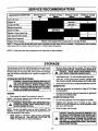
SERVICE RECOMMENDATIONS
MAINTENANCE OPERATION
Every 8 Hours or
25 Hours or Every
SOHours or Every
100 Hours or Every
NOTE 1: Change oil and oil filterafter first 8 hours of operation and then every 50 hours thereafter. Change sooner when operating
under heavy load or in dusty or dirtyenvironmentor in high ambient temperature.
NOTE 2: Clean more often when operatingthe unit under dirty or dusty conditions.
STORAGE
The generator should be started at least once every seven
days and allowed to run at least 30 minutes. If this cannot
be done and you must store the unit for more than 30 days,
use the following information as a guide to prepare it for
storage.
STORAGE
INSTRUCTIONS
WARNING: NEVER STORE ENGINE WITH FUEL IN
THE TANK INDOORS OR IN ENCLOSED, POORLY
,_
VENTILATED
AREAS,
WHEREORFUMES
CAN
REACH AN OPEN
FLAME SPARK
PILOT LIGHT
AS ON A FURNACE, WATER HEATER, CLOTHES
DRYER OR OTHER GAS FURNACE.
•
Remove spark plug and pour about 1/2 ounce (15ml)
of engine oil into cylinder. Crank slowly to distribute oil
I _
CAUTION:
SPRAY
FROMSLOWLY.
SPARK PLUG
HOLE WHENAVOID
CRANKING
ENGINE
•
Install spark plug. Do not connect spark plug wire.
•
Clean dirt, oil and grease from cylinder, cylinder head,
fins, blower housing, rotating screen and muffler area.
•
Close fuel shut-off valve, located beneath the fuel tank.
GENERATOR
•
Clean the generator as outlined on Page 5 ("To Clean
the Generator').
ENGINE
•
Check that cooling air slots and openings on generator
are open and unobstructed.
•
Run engine for about five minutes to warm it.
NOTE: If you did use =gasohol,"drain fuel tank, then run engine
until engine stops from lack of fuel.
OTHER
_
TAINER
OUTDOORS,
AWAY
FROM
OPEN FLAME;
WARNING:
DRAIN FUEL
INTO
APPROVED
CON- I]
BE SURE ENGINE IS COOL
J
TIPS
Do not store gasoline from one season to another.
•
NOTE: Using a fuel additive such as Sears Craftsman® Fuel
Stabilizer, or an equivalent, will prevent gum depositsfrom forming in the generator's fuel system.
•
STORAGE
•
While engine is still warm, drain oil from crankcase.
Refill with fresh oil. See BEFORE STARTING ENGINE on Page 2 for oil recommendations.
Replace your gasoline can if it starts to rust. Rust
and/or dirt in your gasoline can cause problems when
you use it with this unit.
Store in clean and dry area.
_k
12
DANGER: STORAGE COVER IS FLAMMABLE. DO
NOT PLACE THE STORAGE COVER OVER A HOT
GENERATOR. LETTHE UNIT COOL FOR A SUFFICIENT TIME BEFORE PLACING THE COVER ON
THE UNIT. IF YOU PLACE THE COVER ON THE
UNIT BEFORE GENERATOR IS COOL, THE COVER
COULD START ON RRE.
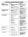
TROUBLESHOOTING
PROBLEM
Engine is running, 10utno
AC output is available.
POINTS
CORRECTION
CAUSE
1. One of the circuitbreakers is open.
1. Reset circuitbreaker.
2. Fault in generator.
3. Poor connectionor defective
cord set.
4. Connected device is bad.
2. Contact Sears Service DepadmenL
3. Check and repair.
4.
Connect another device that is
in good condition.
Engine runs good at no-load but "bogs
down"when loads are connected
2. Engine speed istoo slow.
3. Generator is overloaded.
1. Disconnectshorted electrical load.
2. Contact Sears Service Department.
3. See "Don't Ovedoad the Generator
Shoded generatorcircuit.
on Page 6.
4, ContactSears Service Department.
Short circuitin a connected load.
1.
4.
Engine will not start;or starts
and runs rough.
12.
13.
14.
6.
7.
8.
9.
10.
11.
12.
13.
14.
Replace spark plug.
Drain gas tank; till with fresh fuel.
Open choke fully and crank engine.
Contact Sears Service Department.
Contact Sears Service Department.
Contact Sears Service Department.
Contact Sears Service Department.
Contact Sears Service Department.
Replace battery.
1.
2.
Out of gasoline.
Low oil level.
1.
2.
Fill fuel tank.
.
7.
8.
9.
10.
11.
Engine shuts down dunng operation
Engine lacks power.
1. Load is too high.
2. Dirtyair filter.
Engine "hunts" or faltera.
1. Choke is opened too soon.
2. Carburetoris runningtoo rich
or too lean.
13
1.
2.
3.
4.
5.
Set switch to RUN.
Run/Stop Switchset to STOP.
Dirty air cleaner
Out of gasoline.
Stale gasoline.
Spark plug wire not connected
to spark plug.
Bad spark plug.
Water in gasoline.
Overchoking.
Excessivelyrichfuel mixture.
Intake valve stuckopen or dosed.
Engine has lost compression.
Intake valve stuck opan or closed.
Engine compressionlost.
Failed battery.
1.
2.
3.
4.
5.
Clean or replace air cleaner.
Fill fuel tank.
Drain gas tank; fillwith fresh fuel.
Connect wire to spark plug.
Fill crankcase to properlevel.
1. See "Don't Overload the Generator"
on Page 6.
2. Replace air filter.
1, Move choke to halfway positionuntil
engine runs smoothly.
2. Contact Sears Service Department.
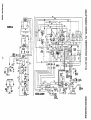
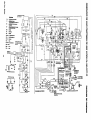
W_[RZNG
D| AGRAH
BtTTERy
I_CT]F
JER
CRAFTSMAN
4200 WATT DELUXE AC GENERATOR
8
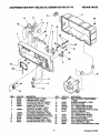
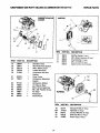
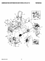
REPAIR PARTS
580.327140
8
7
\
23
"-17
10
3
ITEM
1
2
3
4
5
PARTNO.
83976
83975
66818
66821
68867C
6
6S868C
7
8
g
10
11
12
75207A
75207G
82538
84134
83514
83970
DESCRIPTION
ITEM
PART NO.
CONTROL PANEL (1 REQ.)
CONTROL BOX (1 REQ,)
120 VOLTS AC OUTLET 2(REQ.)
12 VOLTS DC OUTLET (1 REQ.)
120/240 VOLTS, 20 AMP
TWISTLOCK OUTLET (1 REQ.)
120 VOLTS, 30 AMP (1 REQ.)
TWISTLOCK OUTLET (1 REQ.)
30 A CIRCUIT BREAKER (1 REQ.)
AMP CIRCUIT BREAKER (2 REQ.)
ON/OFF ROCKER SWITCH (1 REQ.)
RUBBER GROMMET (1 REQ.)
10 A CIRCUIT BREAKER (1 REQ.)
SYSTEM CONTROL BRD. (1 REQ.)
13
84028
14
15
16
17
18
19
67022
85584
84534A
84534(3
84198
84197
21
22
23
24
25
26
75476
22264
51715
84534B
84335
82542
15
OESCRIPTION
IDLE CONTROL TRANSFORMER
(1 REQ)
RUBBER GROMMET (1 REQ)
BUS BAR (1 REQ)
3.0 X 12MM SCREW (2 REQ)
3.5 X 18MM SCREW (4 REQ)
CIRCUIT BREAKER SHIELD (3 REQ)
CIRCUIT BREAKER
RETAINING BAR (1 REQ)
4.0 X 16MM SCREW (2 REQ)
M4 LOCK WASHER (4 REQ)
M3 HEX NUT (8 REQ)
3.5 X 12MM SCREW (10 REQ)
WIRE HARNESS (1 REQ)
DC OUTLET RETAINING BAR (1 REQ)
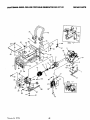
I)rawin
8 No.87407
CRAFTSMAN
4200XL DELUXE PORTABLE
GENERATOR
580.327140
REPAIR PARTS
7O
56
'41
71
_5
66
49
50
"_
DETNL " X "
,€6
'Jr/
3
52
73
I0
35
69
11
3O
68
22-
14
16
CRAFTSMAN
rn M PART
1
2
3
4
5
6
7
8
9
10
11
12
13
14
16
17
18
19
20
21
22
23
25
26
27
30
32
33
34
35
36
37
38
B2551
84021
ENGA1386
66365
84141J 83540J -65791
67451
22129
86307
47480
84508
52858
83208
66476
89476
70644
84346
40976
83083
83071
81917
66825B
85652
45771
74908
86308
65795
66849A
67022
84132
66386
66849
4200 WATr DELUXE AC GENERATOR
CSY.
1
1
1
1
1
1
1
1
2
4
1
2
8
1
2
1
1
3
2
1
1
1
1
2
2
4
4
1
1
2
1
1
2
CRADLE, 4200 W
SUPPORT, Engine
ENGINE, 7.8 HP
HOUSING, Engine Adapter
ROTOR, Assembly
STATOR, Assembly
BEARING
WASHER, M8 Rat
WASHER, M8 Lock
HHMS, 5/16- 24 x 3/4 Long
HHCS, 5/16 - 24 x 7" Long
MOUN_, Vi_
45°
NU'I_,M8 _
BRACKE'_,Muffler
SCREV_, M6 - 1.00 x 12
GASK_, Exhaust
PPHMS, M8- 1.25 x 20 Long
PPHMS, M8 x 35 Long
SCREV_, M8 - 1.25 x 20
SCREEN, Spark An'estor
MUFFLER
PIN, Roll M4 x 10
BEARING, Rear Carrier
MOUN_, Vibra'don
NLrI_,M8 Hex
TAPTITE, M5 - 0.8 x 10 Long
BOLT,M6 - 1.0 x 115 Stator
RECTIFIER, Batten]Charge
TAFT]'iE, M5 - 0.8 x 20 Long
GROMME-'I_,Rubber
MODULE, Drive
ASSY., Brush Holder
TAPTTTE,M5 -0.7x 16 Long
17
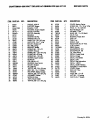
580.327140
REPAIR PARTS
tTEM
PARTNO.
Q_.
39
41
42
43
44
46
47
46
49
50
51
52
53
54
55
56
58
60
61
62
64
66
67
68
59
70
71
72
73
74
75
67025
86494
.86292
77395
83465
78831B
80270
78299
85134
83311
84042
84687
85000
14353621
23762
26850
57593
B2550
92982
B2549
77026
93826
96409
77816
B1432
B1779
B2347
B2555
51757
52857
46476
1
1
5
4
4
4
1
1
1
1
1
1
1
1
1
2
1
1
1
2
1
1
1
1
1
2
2
1
2
2
2
DESCRIPTIO__._._._N
COVER, Bearing Carrier
SCREW, M6 - 1.0 x 16 Lg. Wing
HHCS, 10 - 16 x Self DdU
NU'E M6 Range Lock
GROMMET, Tank
HHMS, M6 - 1.0 x 60 (black)
VALVE, Tank
BUSHLNG, Pla_c Tank
CAP, Fuel
TANK, Fuel
SHIELD, Heat
INSULATION, #2 1/4"Thick
CLIP, Insula'don
WIRE, Ground
SHAKEPROOF, #10
SHAKEPROOF, M6
-RE, Cable Mount
DECAL, Codm_lPanel
DECAL, Danger
DECAL, Heat Shield
DECAL, Data
DECAL, Start Instructions
DECAL, 1-800#
DECAL, MufflerVVaming
ASSEMBLY, ControlPanel
COVER, Hinge
END C_, Tube
HANDLE
HHCS, M6- 1.0 x45
NLr_, M6 - 1.0 Loddng
CAP PLUG, 1"Square
Drawing No.B2554
REPAIR PARTS
CRAFTSMAN 4200 WATT DELUXE AC GENERATOR
580.327140
36
3B
7
7
46
4O
1|A-lIB
_12
9
47
13
2
t8
ITEM
PART NO.
1
2
3
4
5
6
7
6
9
10
11
12
13
14
15
16
17
18
19
2O
21
22
23
24
25
26
78621
76389
88411
89665A
77168
88057
76390
83337A
78658
78659
21857A
76354
81695
76359
78645
76365
72683
98752
89096
88156
21704
78691
76367
76362
78692
786O6
DESCRIPTION
Control Rod Assembly (1 req,)
Piston Pin (1 mq.)
Piston Ring Set (1 req.)
Gear Cover Assembly (1 reg.)
M8 x 52mm Head Bolt {5 req.)
Piston (1 req.)
Pin Retainer Ring (2 req,)
CrankshaftAssembly(1 req.)
Governor"R" Pin (1 req,)
Govern_ ArmThrt_ Washer{1 req.)
Crankcase Assembly (1 req.)
GovernorArm (1 req,)
Oil Seal (1 req.)
GovernorGear Assembly(1 req.)
GovernorGear C-Ring (1 req.)
GovernorSpool (1 req.)
1/8"NPT Pipe Plug (1 req.)
Camshaft Assembly (1 req.)
Crankcase Gasket (1 req.)
Valve Stem Seal (1 req.)
Cylinder Head Gasket (1 req.)
Oil PressureRelief Cover (1 req,)
Oil Pressure Spring(1 req.)
5/16" Ball (1 req.)
M5 Form Screw (1 req,)
M6-1.0 x 12ram Screw (4 req.)
ITEM
27
28
29
30
31
32
33
34
35
36
37
38
39
40
41
42
43
44
45
46
47
48
49
50
/8
PART NO.
76361
89230
99922
86293
88401
84186
83192
86254
76349
21705B
90082
90081
88396A
83235
80336
88397
77161
77160
76307
88403
72657
88412
76329
21942
DESCRIPTION
GovomorGearThrustWasher(1 req.)
M8-1.25 x 35ram Screw (6 req.)
Spring Washer (1 req.)
Valve Spring Retainer (1 req.)
ValveSpring (2 req.)
Va_e Sp_g Wear Washer(2 re¢)
Gerotar Set (1 mq.)
"o" Ring(1 req.)
Searing (1 req.)
CylinderHead Assembly(1 req.)
ExhaustValve (1 req.)
Intake Valve (1 req.)
Push Rod (1 req.)
Tappet (2 req.)
Oil Pick-upAssembly(1 req.)
RockerCover Gasket (1 req.)
Pivot Ball Stud (2 req.)
GN-t90/220 RockerArm (2 req.)
Rocker Arm Jam Nut (2 req.)
Push Rod Guide Plate (t req.)
1/4" NPT Pipe Plug(1 req.)
Rocker Cover Assembly(1 req.)
Plastic Oil Fill Plug (1 req.)
Complete Long Block
CRAFTSMAN 4200 WAn" DELUXE AC GENERATOR 580.327140
CARBURETORANDAll
CLEANER
REPAIR PARTS
MUFFLER
73
31
45
47
48
/
36
39
-./7
49
44
50
41
ITEM
PART NO.
31
32
35
36
39
90947
90051
80316
9O948
91846
41
42
80303
78631
43
44
45
46
47
48
49
97747
78607
66476
59635
78601
78602
83504
ITEM
73
74
75
76
DESCRIPTION
1
1
2
1
1
Breather Hose
Manifold Head Gasket
M6 x 30mm Screw
Intake Manifold
Carburetor/Air
Box
Gasket
Canal Cover
Carburetor Manifold
Gasket
PART NO.
89476
40976
88688
66476
83038
DESCRIPTION
Muffler
Gasket (1 req.)
M8 x 20mm Capscrew (2 req,)
Small Muffler (1 req.)
M6 x 12 HHFS (2 req.)
Spark Arrestor (not shown)
79A
79B
Carburetor (220cc)
Air Cleaner Base
1
1
1
1
M6 x 12mm Capscrew
#8 x 3/8" Plastite Screw
Air Filter
Precleaner
Choke Knob
j
FLYWHEEL
9O
/
81
19
ITEM
PART NO.
DESCRIPTION
78
79A
80
81
90
82774
77182T
83312
81810
A2482
Woodruff Key (1 req.)
Flywheel (1 req.)
Conical Washer (1 req.)
M16 Hex Nut (1 req.)
Recoil Cup (1 req.)
8O
CRAFTSMAN 4200 WA_" DELUXE AC GENERATOR 580.327140
REPAIR PARTS
8
25,
I0
12
26
23
24
_
L.O.S. WITH ENGINE
\
27
20
29
28
30
PART NO.
QTY.
20
72347
21
86962
84195
L.E.D. Assembly (1 req.)
Low Oil Shutdown Decal (1 req.)
Spar k Plug= (1 req.)
Governor Lever (1 req.)
22
85953
Wear Washer (1 re(].)
10
85620
Black Sleeving
23
83502
Adjust Screw (1 req.)
12
84329
3-pin Male Connector
24
83512
M8x
13
00185271
Housing (1 req.)
White Wire Assembly (1 req.)
25
78604
Governor Spring (1 req.)
14
22097
M6 Lock Washer (2 req.)
26
66476
M6 x 12ram Capscrew (1 req.)
15
82891
M6 x 30mm Screw (2 req.)
27
83503
MS Lock Nut (1 req.)
16
81675
Ignition Coil (1 req.)
28
83781
Governor Bracket (1 req.)
17
84274
Tinnerman
29
86384
Governor Rod (1 req.)
18
87221A
Low Oil Shutdown
30
86037
Anti-lash Spring (1 req.)
ITEM
ITEM
PART NO.
DESCRIPTION
7
78653
Run/Stop Switch (1 [eq.)
8
85272
9
Module
19
45756
(1 req.)
DESCRIPTION
15mm Taptite
Screw (1 req.)
Clamp (1 req.)
(1 req.)
M6 x 10ram Screw (1 req.)
20
CRAFTSMAN
4200 WAn" DELUXE AC GENERATOR 580.327140
REPAIR PARTS
RECOIL STARTER
OIL SWITCH AND OIL FILTER
91
/
82
2
6
86
WITH OIL FILTER
ITEM
1
2_
3
4
5
6
88
4
PART NO.
DESCRIPTION
94820
91848
84892
92978
99236
70185
EXPANSION PLUG (1 REQ.)
OIL FILTER GASKET (1 REQ.)
OIL FILTER ADAPTER (1 REQ.)
M6 x 20ram SCREW (2 REQ.)
OIL PRESSURE SWITCH (1 REQ,)
OIL FILTER (1 REQ.)
21
ITEM
82
83
84
85
86
87
88
89
90
91
PART NO.
DESCRIPTION
92984
45756
78609
78608B
90695A
89739
66476
A2799
A2842
78651C
TOP WRAPPER (1 REQ.)
M6 x 10ram SCREW (4 REQ.)
COVER BOLT (2 REQ.)
SEARS AIR BOX COVER (1 REQ.)
BLOWER HOUSING (1 REQ.)
LOWER WRAPPER (1 REQ.)
M6 x 12ram CAPSCREW (9 REQ.)
RECOIL ASSEMBLY (1 REQ,)
RECOIL CUP (I REQ.)
BACKPLATE (1 REQ.)
FOR CALIFORNIA
RESIDENTS
ONLY WHEN SEEKING SERVICE
IN CALIFORNIA
CALIFORNIA EMISSION CONTROL WARRANTY STATEMENT
YOUR WARRANTY
RIGHTS AND OBLIGATIONS
The California Air Resources Board and Sears Roebuck and Co., USA (Sears), are pleased to explain the
emissions control system warranty on your 1995 and later lawn and garden equipment engine. In California new
utility and lawn and garden equipment engines must be designed, built, and equipped to meet the State's stringent
anti-smog standards. Sears must warrant the emission control system on your lawn and garden equipment
engine for the periods of time listed below provided there has been no abuse, neglect, or improper maintenance
of your lawn and garden equipment engine.
Your emission control system includes parts such as the carburetor and the ignition system.
Where a warrantable condition exists, Sears will repair your lawn and garden equipment engine at no cost to
you. Expenses covered under warranty include diagnosis, parts, and labor.
MANUFACTURER'S
WARRANTY
COVERAGE
The 1995 and later utilityand lawn and garden equipment engines are warranted for two years. If any emission
related part on your engine (as listedbelow) is defective,the part will be repaired or replaced by Sears.
OWNER'S
WARRANTY
RESPONSIBILITIES
As the lawn and garden equipment engine owner, you are responsiblefor the performance of the required
maintenancelistedin yourOwner'sManual. Sears recommendsthatyou retainall receiptscovering maintenance
on your lawn and garden equipmentengine, but Sears cannotdeny warranty solelyfor the lack of receiptsorfor
your failure to ensure the performance of all scheduledmaintenance.
As the lawn and garden equipment engine owner, you should be aware that Sears may deny you warranty
coverage if your lawn and garden equipment engine or a part of it has failed due to abuse, neglect, improper
maintenance, unapproved modifications, or the use of parts not made or approved by the original equipment
manufacturer.
You are responsible for presenting your lawn and garden equipment engine to a Sears authorized repair center
as soon as a problem exists. Warranty repairs should be completed in a reasonable amount of time, not to exceed
30 days.
If you have any questionsregardingyour warranty rightsand responsibilities,you should contact your nearest
authorized service center or call Sears at 1-800-473-7247.
WARRANTY
COMMENCEMENT
DATE
The warranty period beginsonthedate the lawnand gardenequipment engineisdelivered tothe original,end-use
purchaser.
LENGTH OF COVERAGE
Sears warrantsto the initialownerand each subsequentpurchaserthat theengine isfree from defectsin materials
and workmanshipwhichcause the failure of a warranted part for a period of two years.
22
WHAT IS COVERED
REPAIR OR REPLACEMENT
OF PARTS
•
Repair or replacement of any warranted part will be performed at not charge to the owner at an approved
Sears servicing center.
•
If you have any questions regarding your warranty rights and responsibilities, you should contact your nearest
authorized service center or call Sears at 1-800-473-7247.
WARRANTY PERIOD
Any warranted part which is not scheduled for replacement as required maintenance, or which is scheduled only
for regular inspection to the effect of =repair or replace as necessary" shall be warranted for 2 yearS. Any warranted
part which is scheduled for replacement as required maintenance shall be warranted for the period of time up to
the first scheduled replacement point for that part.
DIAGNOSIS
The owner shall not be charged for diagnostic labor which leads to the determination that a warranted part is
defective if the diagnostic work is performed at an approved Sears servicing center.
CONSEQUENTIAL
DAMAGES
Sears may be liable for damages to other engine components caused by the failure of a warranted part still under
warranty.
WHAT IS NOT COVERED
All failures caused by abuse, neglect, or improper maintenance
are not covered.
ADD-ON OR MODIFIED PARTS
The use of add-on or modified parts can be grounds for disallowing a warranty claim. Sears is not liable to cover
failures of warranted parts caused by the use of add-on or modified parts.
HOW TO FILE A CLAIM
If you have any questionsregardingyour warranty rightsand responsibilities,you should contact your nearest
authodzed service center or call Sears at 1-800-473-7247.
WHERE TO GET WARRANTY SERVICE
Warranty services or repairs shall be provided at all Sears authorized service centers.
MAINTENANCE,
REPLACEMENT
AND REPAIR OF EMISSION
RELATED
Any Sears approved replacement part used in the performance of any warranty maintenance
related parts will be provided without charge to the owner if the part is under warranty.
PARTS
or repair on emission
EMISSION
CONTROL
WARRANTY
PARTS
LIST
1. Carburetor Assembly
2. Ignition System
a. Spark Plug, covered up to maintenance schedule.
b. Ignition Module
3. Crankcase Breather Tube
4. Exhaust Manifold
MAINTENANCE STATEMENT
The owner is responsible for the performance
of all required maintenance as defined in the owners manual.
23
TWO YEAR LIMITED WARRANTY FOR DELUXE PORTABLE GENERATORS
SEARS warrantsto the Odginal purchaserthat the aHernatorand engine for itsportablegeneratorwillbe free from defectsin
rnstedaisor workmanshipfor the itemsand periodset forth below fromthe date of odginalpurchase.This warrantyis not
_ransferableand appliesonlyto portablegeneratorsdriven bythe GN-SeriesSears warrantedengine.
Altemstor
Engine
CONSUMER*
2 years (2nd year parts only)
2 years (2nd year parts only)
COMMERCIAL*
I year
I year
' NOTE: For the purpose of this warranty "Consumer Use" means personal residential householdend emergency use
k)yoriginal purchaser, not to be used as • pdmary source of power. "Commercial Use" means ell other uses, Including
rental, €onstnJCtlon,commerclst,primary source of realdentfalhousehold power end income producing purposes.
Dnco a generator has exbedenced commercial use, It shall thereafter be considered a commercial use generator for
lhe purpose of this warranty.
:)udngsaid warrantyperiod,SEARS will, at its option,repairor replaceany part which,upon examinationby SEARS, is
=oundto be defectiveunder normaluse and service**. Startingbatfadesare notwarrantedby SEARS. All transportation
;osts underwarranty,includingreturnto the factory if necessary,are to be bome by the purchaserand prepaidby him. This
tvarmnty does not cover normalmaintenanceand service and does not apply to a generatorset, alternatoror engine,or
)arts whichhave been subjectedto improperor unauthorizedinstallationor alteration,misuse,negligence,accident,overoeding,overapseding,impropermaintenance,repairor storage so as, in SEARS'sjudgment,to adverselyaffect itsperformance and reliability.
** NORMALWEAR:
As with all mechanical devlcea, engines need periodic parts service and replacement to perform well. This warranty will not cover repair when normal use has exhausted the life of a pert or engine.
THERE IS N(_ OTHER EXPRESS WARRANTY. SEARS HEREBY DISCLAIMSANY AND ALL IMPLIED WARRANTIES,
INCLUDING BUT NOT LIMITED TO THOSE OF MERCHANTABILITYAND FITNESS FOR A PARTICULARPURPOSE TO
THE EXTENT PERMITTED BY LAW. THE DURATIONOF ANY IMPLIEDWARRANTIES WHICH CANNOT BE DISCLAIMED IS LIMITED TO THE TIME PERIOD AS SPECIFIED IN THE EXPRESS WARRANTY. LIABILITY FOR CONSEQUENTIAL INCIDENTAL OR SPECIAL DAMAGES UNDER ANY AND ALLWARRANTIES IS EXCLUDED. Somestates
de not allow limitationson how long an impliedwarrantylasts,or the exclusionor limitationof incidentalor consequential
damages,so the above limitationsor exclusionsmay not applyto you. Thiswarrantygivesyou specific legal rightsand you
may also have otherrights,whichvery from state to state.
Forservice, see yournearest SEARS authorizedwarrantyservice facility.Warrantyservicecan be performedonlyby e
SEARS authorizedservicefacility. This warrantywill not apply to service at any otherfacility. At the time of requestingwarranty service,evidenceof originalpurchasedate mustbe presented.
SEARS, ROEBUCK AND CO., Hoffman Estates, IL 60179 U.S.A
24
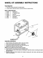
WHEEL KIT ASSEMBLY INSTRUCTIONS
Tools Required:
1.
15/16" box or open end wrench (or socket wrench).
2.
2 13mm wrench, metric box wrench or open end wrench (or socket wrench).
Parts in Wheel Kit Box:
1.
87005A
2
2.
B1760
2
Retaining Pin
10" Diameter Wheel
3.
93728C
2
Axle Stud
4.
94222Q
2
5/8-18 Lock Jam Nut
5.
49808
4
Flat Washer
6.
B1764
1
Mounting Leg
/
4
6
USE EXISTING FASTENERS
TO SECURE: ITE:H #6
Assembly Instructions:
1.
2.
Place the bottom of the generator cradle on a flat, even surface.
Place axle stud through wheel retainer on cradle frame.
4.
5.
Use wrench to secure the axle stud to frame with 5/8-18 jam nut.
Install the other axle stud in the same manner.
NOTE: Be sure to install the wheel with raised hub inboard.
6.
Place flat washer over axle stud, tip unit and install the wheel.
7.
Retain wheel on axle stud with flat washer and retaining pin. Install other wheel on remaining axle shaft in
the same manner.
8.
Remove two front nuts and lock washers from vibration mounting with 13mm wrench. Use these nuts to
retain the mounting leg.
2_
SE/AR8
MANUAL DEL
PROPIETARIO
MODELO NO.
580,327140
CRAFTSMAN°
120/240 VOLTIOS / 4200 VATIOS C-A
12 VOLTIOS C-D CARGAS DE BATERIA
GENERADOR
HORAS:
Lun. - Vie. 8 a.m. a 5 p.m
(TCE)
PRECAUCION:
Lea y Slga las Reglas de
Segurldad • Instrucciones
Antes
de
Operar
Este
Equlpo
SEARS,
NTo. deParteB2552
ROEBUCK
Rev-I (3/27/98)
PORTATIL DE LUJO
•
Ensamble
•
Operaci6n
•
Responsabilidades
•
Servicio y Ajuste
•
Partes de Recambio
and
CO.,
del Cliente
Hoffman Estates,
IL
60179
U.S.A.
SE/A/R
MANUAL DEL
PROPIETARIO
CRAFTSMAN°
120/240 VOLTIOS/4200
12 VOLTIOS C-D CARGAS DE BATERIA
GENERADOR
MODEL NO.
580.327140
VATIOS C-A
Cada Maquina
modelo.
PORTATIL DE LUJO
Lavadora de Alta Presi6n tiene su propio nt_mero de
El ndmero de modelo de su maquina lavadora de presi6n serd encontmdo
en la calcomania adherida a la unided.
Todas las partes enlistadas aqui adelante pueden ser ordenadas a trav6s
de los Centros de Servicio de Sears, Roebuck and Co. y la mayoria de las
Almacenes de Venta al Detal.
Sl NECESITA
REPARACIONES
O PARTES
PARA SERVICIO
REPARACION
ESTE NUMERO
SIEMPRE
PROPORCIONE
LA SIGUIENTE
INFORMACION
CUANDO ESTE ORDENANDO PARTES DE REEMPLAZO:
•
PRODUCTO
PRESION
m MAQUINA
•
NUMERO DE MODELO--
•
NUMERO DE LA PARTE
•
DESCRIPCION
LAVADORA
DE ALTA
DE
LLAME A
580.327140
DE LLAMADA
GRATUITA
1-800-4,REPAIR
(1-800-473-7247)
PARA INFORMACION ACERCA
DE PARTES DE RECAMBIO Y
ORDENES, LLAME A SETE NUMERO DE LLAMADA GRATUITA:
1-800-FON-PART
DE LA PARTE
A su mercancia de Sears se le ha afiadid valor debido a que Sears tiene
unidades de servicio en toda la naci6n equipades con t6chnicos entrenados por Sears...tdcnicos profesionales entranados especificamente en
los productos de Sears, poseyendo las partes, la herramientas y los
equipos neceesarieos para asegurale que vamos a satisfacer nuestro
comprosio con usted, le damos servicio a Io que vendemos.
(1-800-366-7278)
SEARS,
ROEBUCK
and
CO.,
Hoffman Estates,
IL
60179
U.S.A.
Impre_ en les I_.U.A.
REGLAS DESEGURIDAD
HACER
CONTACTO
CON DESCONECTE
LA BUJIA Y ASIELPREVENIR
ACCIDENTALES
CUANDO
ESTA A
PRECAUCION:
SIEMPRE
CABLE DEENCENDIDO6
LA BUJIA Y COLOQUELO
DONDE
NO PUEDA
k INSTALANDO, TRANSPORTANDO, AJUSTANDO O HACIENDO REPARACIONES EN SU GENERADOR.
IMPORTANTE
ESTE GENERADOR ESTA DISEI_IADOUNICAMENTE PAPA SER UTILIZADO EN EXTERIORES. ES PELIGROSO UTILIZAR
ESTE GENEPADOR DENTRO DE CUALQUIER EDIFICACION O RECINTO, INCLUYENDO EL COMPARTIMIENTO PARA
GENERADOR DE UN VEHICULO RECREACIONAL (VR). PUEDE OCURRIR EXPLOSION. I.AS MODIFICACIONES REALIZADAS POR EL USUARIO, INCLUYENDO VENTILACION DEL ESCAPE Y/O VENTILACION DE ENFRIAMIENTO NO
ELIMINARAN EL PELIGRO.
dat_arse,y pueden causar daSo a la propiedady/o des•
Siesta unidad es ulJlizadacomo fuente de energla de
carga eldctdca.
reserva en ca.sode que falle el sorvlclo de energia, siga
los siguientespasos: ANTES DE CONECTAR EL GEN•
Elmotor_ gperador consumeoxygen?
yproducegas
ERADOR A UN SISTEMA ELECTRICO, ABRA EL INoe monoxioooe carbonoMORTAL a traves oe susistema
TERRUPTOR AUTOMATICO PRINCIPAL DE CIRde escape. Este gas es deligroso, si es respirado en
CUITO O EL INTERRUPTOR PRINCIPAL QUE ACTIVA
concentraciones suflcientes puede causar I_rdida del
EL SISTEMA PAPA AISLAR EL SISTEMA DEL GENcor_c,im_entoy a_n la muerte. Unicamento operar este
EPADOR DEL SERVICIO ELECTRICO. LA FALLA AL
equtpoen extertores, en dreas bien ventiladasdonde los
AISLAR EL GENEPADOR Y LQS SISTEMAS DE SERV_s_s del escape no se puedan acumular y poner en
ICIOS PUEDE CAUSAR DANO AL GENERADOR Y
ro la gente o los animales.
PUEDEN TAMBIEN RESULTAR EN LESION O
•
La
gasolina
es extmmadarnente INFLAMABLE y sus
MUERTE DE LOS TRABAJADORES DEL SERVICIO
vapores son EXPLOSIVOS. Cumpla todas las leyes que
ELECTRICO DEBIDOA LA RETROALIMENTACION DE
regulan el almacenaje y manejo de la gasolina. NO
LA ENERGIA ELECTRICA
permda que se fume, llamas abiertas chispaso calor a
su alrededor mientras estd manejando gasoPna. Evitar
derramar gasolina sobre un motor caliente. NO Ilene el
tanque del combustible mientras el motor estd funclonando o est_ caliente. Limpie cualquier derrame de
gasolinaantes de encender el motor.
•
NO Ilene compJetamenteel tanque de combusbble.Deje
algo de espac_oen la parte supertordel tanque para la
expansi(_ndel combusbble,de otra forma el combustible
se puede expandiry derramarse sobre el motorcaliente.
•
Este generador summistravoltajes elfJctncosaltospeh•
Drene toda la gasohna del tanque antes de transportar
grosos. Sea cuidadoso para prevenir descargas el_ctnsu generador dentro de su carro u otro vehiculo.
cas extremaclamentepeligrosas y posiblemente letales.
•
NO almacene el generador con combustible dentro del
Nunca permtta que persona(s) no cahficada(s) opere o
tanquedonde los vaporesde lagasolinapuedan alcanzar
de serv_ctoa la untdad
una llama abterta, una chispa, o una luz de piloto,como
•
NO opere este equipobajo la Iluvia,sobre superftciescon
en un homo, un calentador de agua, una secadora etc.
agua, cuando est_ descalzo, o cuando tonga las manos
Puede resultar en FUEGO o EXPLOSION.
o los pies hdmedos. Ocurrird una descarga eldctnca
•
NO inserte ningdn objeto o herramientaa _avds de las
pehgrosa
ranuras del atre de enfnamiento o de las aperturas del
•
El sdenciador contrachtspas puede calentarse excesP
motor o del generador, a_n cuando el motor no est6
vamente. NO opere este equipo en dreas donde materifuncionando.Puede resultar en da_o a la untdad o en
ales combusbbles como pasto hojas o productos de
lesk_npersonal.
pape puedan entrar en contacto con el silencJador.
•
NO mtente cambiar la velocidad de r6giman del motor.
•
Mantonga todas las conexiones el_ctricas, cables de
Los valoresde fdbrtcason correctoscuando usted recibe
extensibn, etc., en buenas cond_cJones.Las conexiones
la unldad Las velocidades del motor excestvamente
eldctricas o juegos de cables gastados gastados,
altas pueden resultaren lesi6no da_o al equipo.
deshilachados, o daRadosde otra torma pueden causar
•
NO utthcela unidad si est_ da_ada. Repare o reemplaos
descarga eldctrica peSgrosay tambi_n puede ocas_onar
todos los componentesdaSades o defectuososantes de
daRoal equtpo y/o la propmdad.
hacer funcionar la unidad.
•
El Cbdigo EI6ctnco Nactonel requiem que el generador
•
NO
permitaque n_5osoperen o den serv_ctoel generador.
estd conectado correctamente a tierra fis_caaprobada.
Los cbdlgos eldctncos locales tarnbl_n pueden requenr
•
Lea culdadosamente su Manual del Propietario. Uniuna aproplada conex_(_na tierra de la unidad Vea la
camente se debe perm_tirel uso de este producto a
secci6n de MONTAJE para mds mformactbn en la con_aarSOnas
que conozcan estas reglas de seguddady que
exl_)na tierra.
yan sido mstruidascorrectamente en la utilizaci(_nde
este producto
•
Los calibres de los cables de los juegos de conex_ones
eldctdcasy cables deben set Io suficmntementegrandes
para manejar la carga eldcldca mdxima alas cuares ellos
serdn sujetos La mayorta de dJspositNosnecesdan de
juegos de cables clasificadosen 125 voltiosCA de 20 a
30 amperios o 250 volttosCA a 20 ampenos (o mayor)
Algunos disposltivospueden requerir una clasificact6n
mayor o menor. Refidrase al manual del Propietario de
disposilJvoel6ctricopara las recomendecionesdel fabd_apte..Los jue.gosde cables que son muy peque_os en
larnetro o muy largosse sobrecalentardn, para despuds
I
_
ESTO
SIGNIFICA
"iATENClONtttt
iMANTENGASE
ALTERA!!!PRECAUCIONES
SU SEGURIOAO DE
ESTA
EN PELIBUSQUE
ESTE SlMBOLO
PARA SEI_IALAR
IMPORTANTES
SEGURIDAD.
GRO."
I
I
FELICITACIONES
per su compra del Generador Sears
Craftsman. Este ha sido disettado, concebido y fabricado
para brlndade la mejor conflabilidad y el mejor desempei'lo
posible.
si _iene cualquier problema qua no pueda solucionar con
factlidad, por favor contacte su Centro/Departamento de
Servicio Sears mds cercano o Ilame al ndmem 1-800
indicado en la cubiarta de esta manual. Tenamos t_nicos
competentes y bien entrenados y las herramientas apropiadas para darle servicio y reparar esta unidad.
Por favor lea y conserve este manual. Las instrucciones Io
capacitardn para ensamblar y rnantener apropiadamante
su generador. Siempre siga la "REGLAS DE SEGURIDAD."
ESPECIFICACIONES
Especiflcaclones del Generador
POTENCIA NOMINAL
MAXIMA
4200 Watts (4,2 kW)
VOLTAJE NOMINAL
120/240 Voltios AC
CORRIENTE DE CARGA
NOMINAL MAXIMA
35/17.5 AC amperes
FRECUENCIA
60 Hz at 3600 rpm
NOMINAL
FASE
Uno Fase
CARGA LA BATERIA
Amps: 10 DC amperes
Vohtos: 12 Voltios DC
Especlflcaclones
NUMERO
DEL
MODELO
NUMERO
580.327140
del Motor
MOOELO DEL MOTOR
GN-220
DESPLAZAIMENTO
220cc
BUJIA: Tipo:
DE
SERIE
Espacio Establecido
TIEMPO DE OPERACION
MAXIMO CON
EL TANQUE LLENO (hrs)
FECHA DE
COMPRA
LOS NUMERO DEL MODELO Y DE SERIE SE ENCUENTRAN
EN I.A CALCOMANIA
ADHERIDA AL
GENERADOR
DEBE REGISTRAR
EL NUMERO DE SERIE Y LA
FECHA DE COMPRA Y MANTENERLOS
EN UN
LUGAR SEGURO PARA REFERENCIAS FUTURAS.
ACUERDO
DEL PRODUCTO
DE MANTENIMIENTO
Estd disponible en este producto un Acuerdo de Mantenimiento Sears. Contacte su almac6n Sears mds cercano para detalles.
REPONSABILIDADES
DELCLIENTE
•
Lea y siga las reglas de seguridad.
•
Siga una programacibn de mantenimiento regular, cuidado y utilizaci6n de su generador.
•
Siga las instrucciones de las secciones de "Mantenimiento" y =Almacenaje" de este Manual del Propietado.
CAPACIDAD
DE GASOLINA
,
Champion RC12YC or
equivalent
0.030 inch (0.78mm)
carga
completa
3
carga
1/2
5
4 gallones U.S.
ACEITE (mesos de verano)
(mesos de invierno)
SAE 30
SAE 5W20 o 5W30
CAPAICIDAD
870ml (confinrode aceite)
620ml (sinfiltro deaceite)
DE ACEITE
NOTA: Este generador estd equipado con un silenciador
contrachispas. El contrachispas debe ser mantenido funcionando correctamente pot el propietado/operador.
Es requerido por ley un contrachispas en el estado de
California (Secci6n 4442 del C6digo de Recursos Pt_blicos
de California). Otros estados pueden tener leyes similares.
Las leyes federales se aplican en tierras federales.
TABLA DE CONTENIDOS
REGLAS DE
SEGURIDAD ......... PARTE INTERNA
ACUERDO
DE MANTENIMIENTO
RESPONSABILIDADES
ESPECIFICACIONES
DE LA CUBIERTA
.................................
DEL CLIENTE .........................
DEL PRODUCTO
.......................
MONTAJ E .......................................................................
OPERACION
................................................................
MANTENIMIENTO
.....................................................
SERVICIO Y AJUSTES ................................................
11
RECOMENDACIONE8
12
DE SERVICIO
1
ALMACENAJE
1
PUNTOS DEL DIAGNOSTICO
1
DIAGRAMA DE CONEXION
3
4-8
........................
..............................................................
12
DE AVERIAS .............. 13
........................................
14
PIEZAS DE RECAMBIO ..........................................
15-22
GARANTIA ...............................................................
23-26
9-10
Indlce
-AAlmacenaje ..............
Antes de Encender .........
12
5
Apagado de Presi6n ........
Baja de Aceite ............
8
5
Carga de la Bater'B .........
Cargas El_ctricas ..........
7
5
5
-O-
-J-
Operaci6n...............
4-8
4
-LParado del Motor ..........
Lubdcaci6n ...............
5
-M4,10
13
14
-EEncendido del Motor ........
5
Especificaciones ...........
1
23-26
5
8
Partes, mparaci6n
......
6
15-22
°R-
Mantenimiento
Acuerdo ....................
1
Recomendaciones
de Servicio ..............
Limpieza del Generador .......
Mantenimientodel motor.......
RecomendacionesGenemles...
Maintenimiento del Generador
9
9
9
9
Reglas de
Seguridad ....
dentrode la cublelta
Responsabilidedes del
Cliente ...................
1
Medidas de Seguridad para
la Baterla .................
6
oS-
Montaje ..................
Motor
-GGaranfia ..............
Gasolina .................
Guta de Referencia .........
Nivel de Aceite ............
4
-p11
-DDepurador de Aim .......
Diagn6stico de Avedas .....
Diagrama do Conexi6n .....
Interruptores Automdticos
de Circuito ................
Juegos de Cables ..........
-CCarburador ..............
-N-
-J=
Ajuste del carburador.........
Nivel de aceite ...............
Velocidad ..................
3
11
5
11
Servicio y Ajuses .........
Sistema de Enfriamiento.....
Sobrecarga ...............
12
11
9
8
-TTerminal de Conexi6n
a Tierra ..................
Tomas ...................
3
3
, MONTAJE
Su generadorCA fue ensambladocompletamenteen la fi'dbrica.
Se encuentralistopara ser utilizadodespu_sde haber recibido
el servicio apropiado con el aceite lubricante y combustible
recomendado.
CORDONESDE 3 ALAMBRES
SI TIENE PROBLEMAS CON EL MONTAJE DE SU GENERADOR POR FAVOR LLAME A LA LINF_ADE AYUDA DE AL
GENERADOR AL 1-800-222-3136.
IMPORTANTE: CUALQUIER INTENTO DE HACER FUNCIONAR EL MOTOR ANTES DE HABER RECIBIDO SERVICIO CON EL ACEITE RECOMENDADO RESULTARA EN
FALLADEL MOTOR.
_
TIERRA
PARA RETIRAR EL GENERADOR DE LA
CAJA
•
Coloque la caja sobre una superficieplana y rfgida las fiechas =THISSIDE UP"apuntandohacia arriba.
•
Abra cuidadosamente las tapas superiores de la caja de
envfo.
•
Corte las esquinas en una de las terminacionesde la caja
de envioy acuestela caja porese lado.
•
Retireel materialde empaque, re,enos de la caja, etc.
•
Retireel generadorde la caja de envfo.
.A--L NEOTRO
FIG. 2
CORDONES DE
l_]ot
y_ _k_
j'J
X (cargado)
_l_cargado) "_ "
TIERRA
(verde)
JUEGOS DE CABLES Y ENCHUFES
CONECTORES
FIG. 3
TOMA DOBLE DE 120
VOLTIOS
CONECTANDO A TIERRA EL GENERADOR
Utilice 0nicamente cables
de extensi6n de alta calidad y con buen aislamiento
de las tomas el_ctdcastipo
"doble" de 120 voltios.
Todos los juegos de cables
utilizadosdeben ser clasificados como de 125 voltios
a 15 CA amperios o mayores para la mayorfade los
FIG. 1
dispositivos el6ctricos.
Conserve los cables de extensi6ntan cortoscomo sea posible,
preferiblementemenosde 15 pies de Iongitud para prevenircaidas de voltajesy sobrecalentamiento
de los cables.
TOMAS DE 120 VOLTIOS, 30 AM
Para la toma NEMA L5-30R con traba por giro 30 amp de 120
voltios, un juego de cables con buen aislamiento con un
enchufe conector con treba de giro NEMA L5-30P debe ser
apropiadamenteconectadoa la toma y a la carga deseada CA
60 Hz monof&sicade 120 voltios.El juego de cables debe ser
clasificadocomo de 30 CA amperios a 125 voltios (o mayor)
para la mayorfa de los dispositivosel_tricos (Fig. 2).
El Cx_igo El_,ctricoNacionalrequiemque el marcoy las partes
conductorasel_:,ctdcas
extemas de este generadorestbnconectadas apmpiadamentea una tierra fisica aprobada.Los c6digos
eldctricoslocalestambi_npueden requeriruna conexi6na tierra
apropiadade la unidad. Pare tal prop6sitoes propomionadoun
TERMINAL DE CONEXION A TIERRA en la base del bastidor
(Fig.4). Generalmenteconectandoun alambrede cobretrenzado No. 12 AWG (Calibrede AlambreAmericano)al terminalde
conexibn a tierra y a un barra (electrodo)dirigida a tierra de
cobre o lat6n, propomionauna proteccibnadecuada en contra
de descargael6ctrica.Sin embargo,los cbdigoslocalespueden
variar bastante.Consultecon un electricistalocal para requisitosde conexi(_na tierraen su_rea.
La conexi6n a tierra apropiada del generador le ayudard a
previnir descargas eldctricas en el caso que se presente un
condici6nde averfa que se descarguea tierra en el generadoro
en los dispositivose!_ctricosconectados.La conexiona tierra
apropiadatambidn ayuda a disipar la electricidad estdtica, la
cual comfinmentese acumulaen los dispositivosno conectados
a tierra.
ALAMBRE DE COBRE
TRENZADO NO. 12 AWG
TOMA DE 120/240 VOLTIOS, 20 AMP
Es necesario un enchufe conector complementadotipo traba
por giro de 120/240 voltios,30 amp cuando estdutilizandoesta
toma. Es necesarioun juego de cables de 4 alambres,clasificado en 30 CA amperios a 250 voltios (o mayor) y debe ser
conectado al enchufe y alas cargas deseadas. Orden NEMA
tipoL14-30P.
BARRA (ELECTRODO)
3
FIG. 4
OPERACION
CONOZCA
SU GENERADOR
LEA ESTE MANUAL DEL PROPIETARIO Y LAS REGLAS DE SEGURIDAD ANTES DE HACER FUNCIONAR SU
GENERADOR. Compare las ilustraciones con su generador para familiadzarse con las Iocalizaciones de los controles
y ajustes. Guarde este manual pare referencias futuras.
TANQUEDECOMBUSTIE
TOMADE120-VOLTIOS
30AMP
DEPURADOR
DEAIRE
TOMADE
1201240-VOLTIOS
_TOMASDOBLES
DE12-VOLTIOS
INTERRUPTORES
AUTOMATICOS
DE
ClRCUITO
TOMAS =DOBLES" DE 120 VOLTIOS - Pueden ser ut=lizadas para summistrar energia el_ctnca para el funcJonamlento de CA de 120 volt=osa 20 amps, monofds=ca,
60 Hz, cargas de =lum=naci6n electnca de CA, electrodom6sticos y motores.
TOMA DE 120 VOLTIOS, 30 AMP - Puede ser ut=l,zada
para suministrar energta el_=_ctricapara el funcionamiento
de CA de La conexi6n a tierra apropiada del generador le
ayudard a prevenireldctrica de CA, electrodomdsticos, herremientas y motores. Los conectores de c_erre por g=roson
necesarios cuando utlhce esta toma.
TOMA DE 120/240 VOLTIOS - Puede ser utilizada para
suministrar energia el6ctrica para el funcionamJento de CA
de hasta 240 voltios a 30 amps, monofdsica, 60 Hz, cargas
de iluminaci6n eldctrica de CA, electrodomdsticos, her-
ram=entas y motores. Los conectores de cierre por giro son
necesanos cuando utilice esta toma.
INTERRUPTORES
AUTOMATICOS
DE CIRCUITO CA Protege el generador contra la sobrecarga eldctrica. Los
mterruptores automdt_cos son del t_po=pulsar para act=vaf'
para cargas de 15 amp, 20 amp y 30 amp.
SILENCIADOR
CONTRACHISPAS
- El silenciador del
escape t,ene una pantalla contrachispas.
INTERRUPTOR RUN/STOP DEL MOTOR - Debe ser colocado en RUN para encender el motor. Coloque el interruptor en STOP para detener el motor.
MEDIDOR DEL NIVEL DE COMBUSTIBLE - Indica el nivel
del combustible en el tanque de combustible.
OPERACION
ANTES DE ENCENDER
Agmgue
EL MOTOR
Aceite de Motor Antes del Arranque Inlclal:
Quite una de las Tapas Amadllas de Llenado del Aceite
(Figura 2 en la Pagina3) y agregue aceite de motor hasta
que el nivel del aceite est6 en el punk) de rebose. Examine
el nivel de aceite del motor antes de arrancar de ahora en
mds. Si el nivel del aceite estd debajo del punto de rebose,
Ilene hasta el nivel apropiado (Fig. 5).
Los aceites recomendados
rank) los meses de verano:
sustituto aceptable. Durante
20 o 5W-30. NO USE SAE
incluyen los siguientes: DuSAE 30. SAE 10W-30 es un
los moses inviemo: SAE 5W10W-40.
La capacidad de aceite del critter es unos 720ml.
aditivos especiales.
I
SI SE OPERA EL GENERAl)OR EN LA LLUVIA, EL I
USARIO PODRIA RECIBIR UN CHOQUE ELEC-I
ADVERTENCIA!
TRICO
Y LA HUMEDAD
SE DEBE
PODRIA
EL GENERADOR
DA_IAR LOSSECO.
COM- I
PONENTES DEL GENERADOR.
C6mo arrancar el motor:. Desconnecte todas las cargas
el6ctricas del generador,
•
Localice el interrupter de Encender/Apagar (On/Off)
del Control de Marcha en VacJo en el tablero de control
y p6ngalo en la posicibn OFF.
•
Localice
el interruptor
de Funcionar/Parar
(RUN/STOP) ala par de la base del depurador de aim
y p6ngalo en RUN(Figura 6).
No use
I
FUNCIONAM
clonar o arramcar el motor antes de hacede el
PRECAUCION: Cualquler tentative de hater funservlclo
suite
en fella
aproplado
del motor.
con et acelte recomendado re-
! I
.---T
SEMI-ABIERTO
FIG. 6
FIG. 7
•
C
ierre el estrangulador en la posici6n FULL (TOTAL)
deslizdndolo a]a posici6n ala)eda en la direcci6n indicada por una flecha en la caja del depurader de aire
(Figura 7).
Agarre la empuSaclura del arrancador y jale lentamente hasta que se sienta resistencia. Entoncesjale
rdpidamente. Repita el procedimiento si fuera necesario con el estrangulador (choke) ligeramente abierto.
FIG. 5
Agregue gasoline:
Llene el tanque de combustible con gasolina UNLEADED (SIN PLOMO) fresca y limpia. Tambidn
puede utilizar gasolina grade REGULAR con plomo.
NO UTILICE
GASOL[NA
PREMIUM.
SEA CUIDADOSO DE NO LLENAR EN EXCESO EL TANQUE
DE COMBUSTIBLE.
Cuando el motor arranca, abra el estrangulador gradualmente.
CONEXION
PRECAUCION: No Ilene exceso el tanque de cornbustlble. Slempre deJe espaclo pare la expansl6n
del combustible.
ADVERTENCIA: NUNCA LLENE EL TANQUE DE
COMBUSTIBLE DENTRO DE UNA INSTALACION.
NUNCA LLENE EL TANQUE DE COMBUSTIBLE
CUANDO EL MOTOR ESTA FUNClONANDO O
CALIENTE NO ENClENDA UN ClGARRILLO O
FUME MIENTRAS ESTA LLENDAND EL TANQUE
DEL COMBUSTIBLE.
COMO OPERAR EL GENERADOR
generador con dls.posltlvos o apmtos en modo de I
funclonamlento
ON" cusndo
esten
conectadas
PRECAUCION! Nunca
arranque,
o pare,
el motor-a J
los tomacorrientes del _lenerador.
5
DE CARGAS
ELECTRICAS
•
Utilizer este generador para operar cargas de 120/240
voltios, monofdsicas, 60 Hz, =luminaci6n CA, electrodom_sticos, herramientas y motores.
•
Conecte y encienda las cargas el_ctricas de 120 o 240
voltios, monofdsicas, de 60 Hertz que se deseen.
•
NO conecte 240 voltios alas
voltios, 120 voltios, 30 amp.
•
NO conecte
panel.
•
NO conecte ninguna carga de 50 Hz al generador.
•
Sume los vatios clasificados de todas las cargas de las
luces, herramientas, electrodom6sticos
y motores alas
_)ue. le estd suministrando energta en un momento.
icno total NO deDe ser mayor a (a) la capacidad de
va!iaje clasificado del genemdor, o (b) la clasificact6n
eel interruptor automdtico del cimuito de la tome que
estd suministrando energia. Vea "NO Sobrecarge el
Generador" en la Pdgina 8.
tomas dobles de 120
ninguna carga trif_sica alas
tomas del
OPERACION
PARADO DEL MOTOR
•
PERNO DE CONTROL
EN VACIO
Desconecte todas las cargas el6ctdcas de las tomas
del panel del generador. Nunca encienda o detenga
el motor con los dispositivos el6ctricos conectados y
encendidos.
•
Deje funcionar el motor sin cargas por vados minutos
pare estabilizar las temperaturas internes del motor y
el generador.
•
Coloque el Interruptor Run/Stop en STOP. Espere que
el motor se detegna completamente (Fig. 6).
•
Cierre la Vdlvula de Corte de Combustible.
COMO OPERAR EL CONTROL
DE MARCHA EN VAC|O
Este provee econom'm en
la operecibn de la unidad
dando mds rendimiento del
combustible cuando estd
operando
la misma a
niveles de velocidad mdximos y norrnales.
Teniendo en cuenta que 6ste
ahorro se obtiene solamente cuando los aparetos
estan conectados al generador.
AUTOMATICO
FIG. 9
CONTROL DE
MARCHA EN VACIO
•
Asequre la Contretuerca del Control Libre contra la
mdnsula del control libre mientras que el motor est_
funcionando dentro de un rango de 25 a 35 Hz.
"Micro Ajuste" del Carburador:
Una vez al control libre
ha sido precalibrado puede utilizer el tomillo del libredel
carburedor para realizar "micro ajustes" adicionales ala
velocidad del control libre del motor-generador.
•
FIG. 8
El sistema consiste de (a) un Tablero de Circuito de Control
de Marcha en Vacio, (b) un Transformador
Detector, (c) un
Electromagneto,
y (d) un Interruptor de Control de Marcha
en Vacio Iocalizado en el tablero de control (Figura 8).
El motor-generador funciona a una velocidad alta regulada
con el Interruptor de Control de Maroha en Vacio en ON
cuando una carga el6ctdca se conecta el generador.
Cuando la carga eldctrica se desconecta, se activa un
Electromagneto para jalar el Choke del motor contra el paro
del sistema de marcha en vacio. El motor entonces funciona a una velocidad (marcha en vacto) reducida.
El electromagneto no puede ser activado con el Interruptor
de Control de Maroha en Vacio en OFF, puesto que el
circuito de potencia estd abierto. El motor funciona a una
velocidad alta regulada (a unas 3000 rpm) si la(s) carga(s)
estd(n) conectada(s) o no.
AJUSTE Y CALIBRATION
MENSULA
DEL CONTROL
LIBRE
Necesitard un volti-metro-ohmimetor para ajustar el control
libre. Puede colocar y ajustar el Control Libre en el Generador De Lujo como se describe a continuaci6n:
Precalibraci6n de Control Libre: Refi_rase al Ensamble
del Control Libre cuando realice el ajuste inicial del Control
Libre.
Con la unidad funcionando y caliente, gire en sentido
de las manecillas del reloj el pemo del control libre
(velocidad mds rdpida), o en sentido contrario de las
manecillas del reloj (velocidad n_s lenta) haste que la
velocidad del motor est6 entre 25 y 35 Hz (1500-2100
rpm). Vea la Figure 9.
Gire en sentido de las manecillas del reloj el tomillo de
ajuste del libre del carburador (velocidad mds rdpida)
hasta que la velocidad del motor est_ entre 38 y 40 Hz.
(2280-2400 rpm).
NOTA: Las velocidades del motor de menos de 38 Hz,
poddan causar que el motor se apague si aplica inesperadamente cargas muy grandes.
MEDIDAS
DE SEGURIDAD
DE LA BATERIA
GAS DE HIDROGENO EXPLOSIVO
PRECAUClON: El almacenar lie batedas hace que
ellis produzcan gas de hldr6geno EXPLOSIVO
mientras se estdn cargando. Una mezcla explosive
permanecerst alrededor de la bateda por largo
tiempo despu_s que ha sldo cargada. La m4s
mfnlma chlspa puede encender el gas y causer una
explosl6n. Dicha explosl(_n puede destrulr la
bateda y causer ceguera u otras leslones serlas.
PRECAUCION: NO permita que se fume, IlamM,
abiertas, chispas o cualquier fuente de calm" elrededor de una bateda. NO utillce nlnguna clise de
encendedor u otra clase de llama pare Ilumlnar y
reviser el nlvel del liquido de la bater_a. Use anteojoe de protecci6n, delantal de caucho y guantce de
caucho cuando trabaje alrededor de la bater_a.
ACIDO SULFURICO CAUSTICO
PRECAUClON: El I[quido electrolftico de la bat=de
es una solucl6n de dcldo sulf0dco extremadamente c_ustJca que puede causer quemaduru
severse. NO permita que el I_quido entre en contacto con ojos, plel, vestldos, etc. Sl sucede un
derrame, I_vese con ague Umpla inmedlatamente.
OPERAClON
CARGANDO
UNA BATERIA
Su generador tiene la capacided de recargar una bate(m
de autorn6vil de 12 voltios descargada o una bater'm para
almacenar tipo servicio. No u_lice la unidad pare cargar
batefias de 6 voltios. No utilios la unidad para hacer girar
un motor que tenga una batefia descargada. Para recargar
las bate(ms do 12 voltios, proceda como se describe a
contJnuaci6n:
•
Revise el nivel del rquido en todas las celdas de la
bator'B. Si es neossario, afiada UNICAMENTE agua
destJlada para cubrir los separadores de las celdas de
la batsrta. NO UTILICE AGUA DE GRIFO.
•
Si la bater'm estd equipada con tapes de ventilaci6n,
asegurese que estdn instaladas y apretadas.
•
Si es necesado, limpie los bomes de la bateria o los
terminalesenerador.
•
Conecte el enchufe del conector del cable de carga de
la bateria a la toma del panel (Fig. 10) indentificado con
las palabras =12-VOLT D.C."
•
Conecte la abrazadera del cable de carga de la bateria
con la agarradera negra al bomo de la bateda o terminal marcado con un NEGATIVO, NEG o (-).
•
Encienda el motor (vea "Encendido del Motor" en la
Pagina 5). Deje funcionar el motor mientras la bats(==
se recarga.
•
Cuando la batefia se ha cargado, apague el motor (vea
"Parado del Motor" en esta pdgina).
NOTA: Utilice un hidrbmeter para autorn6viles pare prober
el estado de carga y condici6n de la baterla. Siga cuidadosmente las instrucciones del fabricante del hidr6meter. En
general, se considera qua una bater'm estd en el 100% de
estado de carga cuando la gravedad especifica de su
liquido (medido por el hidrbmeter) es de 1.260.
SISTEMA DE APAGUE
DEL ACEITE
DE PRESION
BAJA
El motor viene equipado con un detector de prasi6n baja
aceite qua apaga el motor automdticamen_,e cuando la
presi6n del aceite cae debajo de 0.422 Kg/cm =. Si el motor
se apaga por si mismo y el tanque de combustible tiene
suficiente gasolina, examine el nivel del aceite del motor.
Arranque Inciah Un retraso incorporado en el sistema de
apague permite que la presi6n se acumule durante el
arranque. El retraso permite que el motor funciona por
unos 10 segundos antes de detecter la presi6n del aceite.
12 VOLTIOS D.C.
C6mo Se Detecta la Presfon Baja: Si el sistema detecta
presi6n baja del acaite duranto la operaci6n, el motor se
apaga. AI apagarse el motor, el indicador de bajo nivel
de aceite se enciende (ON). Sin embargo, una vez qua el
motor ha parado de girar, esta luz se apaga (OFF).
C6mo Volver e Arrancar:
Si intenta volver a arrancar el
motor en 5 segundos despu6s de que se apaga, el motor
puede NO arrancar. El sistema necesita de 5 a 10 segundos para restablecerse.
PO RECEPTACULOs__-
Si usted vuelve a arrancar el motor despu6s de este de
apague y no ha corregido la presi6n baja del aceite, el
motor funciona por unos 10 segundos como se descrlb|6 anteriormente y Iuego se para.
BATERIA DE 12 VOLTIOS
FIG. 10
?
OPERACION
Si el electrodomt_sUco o el motor no tlenen el vatlaje,
multiplique 220 voltios por la potancia de amperlo para
detarminar los vaUos (voltios x amps = vatios).
NO SOBRERECARGEELGENERADOR
Este generador est_ equipedo con dos interruptores
automdticos del cimuito de 15 amp, uno de 20 amp y otro
de 30 amp, los cuales protegen la unidad en contra de
sobrecarga el_ctdca. El sobrecargar un generador en exceso de su capacidad clasificada de vatiaje puede resultar
en da5o al generador y a los dispositivos el6ctricos conectados al mismo. Siga Io siguiente para prevenir sobrecarga
la unidad.
•
Algunos motores ek_ctricos, tales como los de tipo de
inducci6n, requieren como dos veces y media rnds de
vatios de potancia para arrancar que para funcionar.
Esta sobracarga momentanea de enorgta dura solarnente por unos pocos segundos cuando se arrancan
dichos motores. Cerci6rese de dar tiompo para este
vatiajo alto do arranquo cuando se eligen los aparatos
elt_ctricos para conectar a sus _.enerador.
Primero
calcule los vatios que se neces=tan para arrancar el
motor rods grande. Agregue a esa cifra los vaUos de
funcionamiento de todas las otras cargas conectadas.
•
La GUIA a continuaci6n se provee para asistido en
determinar cuantas piezas su ganerador puede operar
al mismo tiempo.
Sume el vatiaje total de todos los aparatos que se van
a conectar al mismo Uempo. Este total NO debe sor
mayor que la capacidad de vatiaje del generador.
El vatiaje nominal de las luces pueden tomarse de las
bombillas eldctricas.
El vatiaje nominal de las herramientas, electrodomdsticos y rnotoros pueden usualmenta encontrarse en una placa de datos o calcomania pegada en el aparato.
GUIAS DE REFERENCIA
DEL VATIAJE
FUNCIONAMIENTO
VATIOS
Aire Acondicionado (12,000 Btu) ..............................
1700
Cargador de Bater'_a(20 amp) .....................................
500
Recortadora Razante ...................................................
450
1000
Llave de Impacto .........................................................
500
1200
*Bomba de Chorro .....................................................
800
800 a 1000
Segadora de C_sped .................................................
1200
Arenador de Correa (3") ...........................................
Sierra de Cadena ......................................................
Sierra Circular (6-12/')
............................
FUNCIONAMIENTO
VATIOS
Cafetora ....................................................................
1000
*Compresor
2000
(1 HP) ................................................
*Compresor (3/4 HP) ................................................
Rizador de Pelo .................................................
1800
700
*Congolador ................................................................
500
Arenador do Disco (9") ..............................................
1200
Recortadora de Bordes ...............................................
500
Bombillo ....................................................................
100
Homo Micro Ondas ......................................................
700
*Enfriadora
de Leche .................................................
1100
Quemador de Aceite del Homo ...................................
300
Calentador de Ambiente de Aceite Quemado
( 140,000 Btu) ..............................................................
Calentador de Ambiente de Aceite Quemado
(30,000 Btu) ..........................................................
400
150
Pistola Eldctdca de Clavos ..................................
1200
Cocina Eldctnca (un elemento) ...............................
1500
Atom=zador do Pmtura, Sin Aire (de mano) ................. 150
Sarten Eldctnco ...................................................
1250
Rad=o .................................................................
*Ventilador de Homo (1/3 HP) ........................
1200
*Refngerador ...............................................................
Secador de Pelo ............................................
1200
Taladro de Mano (1 ") ...............................................
1100
Taladro de Mano (1/2") ..............................
750 a 1000
Taladro de Mano (3/8") ............................................
500
*Atomizador de Pmtura, Sm Aira (1/3 HP) ................... 600
50 a 200
* Asigne 2-1/2 veces la cantidad de vatios de la lista
para arrancar estos aparatos.
Rec=piente de Cocci6n Lenta200
600
MAINTENIMIENTO
RECOMENDACIONES
GENERALES
El Propietado/Operador es responsable de asegurarse que
todos los trabajce de mantenimiento pedddicos sean terminados a tiempo; que todos Ice problemas sean corregidos; y que la unidad se mantenga limpia y almacenade
apropiadamente. Nunca opera un genarador dafiado o
defectuosos. Siga las recomendacionas de la tabla de
RECOMENDACIONES
DE SERVICIO.
C0mo Camblar el Ace#e: Cambie el aceite despuds de
las pdmeras ocho horas de operaci6n. Carnbie el aceite
cade 50 horas de aqut en adelante. Si se estd usando el
ganerador bajo condiciones de suciedad o polvo, o en
clima extremadamente caliente, cambie el aceite con rnds
frecuencia.
Cambie el aceite mientras el motor estd todav'sacaliente
despul_s de haber funcionado, de la siguiente manera:
PRECAUCION:
I
_IL
_k
coloquelo donde no entre an contacto con la buJla
PRECAUCION: Desconec_ el cable de la buJla y I
antes de trabajar en su generador.
MANTENIMIENTO
DEL GENERADOR
•
El mantenimiento del generador consiste en conservar la
unided limpia y seca. Opera y almacene la unidad an un
ambiente limpio y seco donde no serd axpuesta al polvo,
suciedad, humedad o vapores corrosivos. Las ranuras del
aim de enfriamianto del ganerador no deben estar tapadas
con nieve, hojas, o cualquiar otro material extrafio.
Desconecte el cable de la bujfa y I
=mperelodelabujfa.
Sigaesteprocedlmientocada
_loU
realize manten mientos en el motor o gen-
Limpie el drea alrededor del talx_n drenaje del aceite,
quite el tap6n (Rgura 11)y drene el aceite completamente an un rec=piente adecuado.
Coloque
Revise frecuentementa la limpieza del generadory Iimpielo
cuando est6 con polvo, sucio, con aceite, humedad, o
cuando otras substancias extrafias sean visibles en su
superficie exterior.
NOTA: NO recomendamce utilizar la manguera del jardin
para limpiar el ganerador. El agua puede entrar al sistema
de combustible del motor y causar problemas. Ademds, si
el agua entra al genarador a trav6s de las ranuras dal aira
de enfriamianto, parte del agua serd retenida en los huecce
y desquabrajaduras del aislamiento del devanado del rotor
y el estator. La acumulaci6n de agua y suciedad en los
devanados internos dal generador eventualmente disminuird la resistencia al aislamiento de esos devanados.
PARA LIMPIAR
Utilice un patio hOmedo para dejar limpias las superficies extenores.
•
Puede utilizar un cepillo de cerdas suaves para recoger
la suciedad y los restos sueltos.
•
Pueda ser utilizada una aspiradora para recoger la
suciedad y las particulas.
•
Puede utilizar aira a baja presi6n (no exceder de 25
psi) para soplar la suciedad. Inspeccione las ranuras
del aire de enfriammiento del generador. Estas aperturas se deben mantener limpras y sin obstrucciones.
,_
•
Cuando el aceite ha sido drenado, instale y apriete el
tap6n de drenaje del aceite.
•
Quite el tap_n de drenaje del aceite meta un embudo
de Ilendado limpio an la abertura de tap6n. Llene el
critter del motor con el aceite recomandado hasta que
el nivel del aceite Ilegua al punto de rebose. No liana
axcesivamente por encima del punto de rebose. Se
requieren unos 720ml. VIERTAL LENTAMIENTE.
•
Cuando el cdrter del motor se Ilena hasta el nivel
adecuado, instale y apriete el tap(_n de Ilenado del
aceite.
EL GENERADOR:
•
I
FIG. ll
JETO O HERRAMIENTA
A TRAVES DE LAS I
RANURAS DE AIRE DE ENFRIAMIENTO AUN Sl EL J
MOTOR NO ESTA EN FUNClONAMIENTO. PUEDE I
PRECAUCION:
INSERTE
NINGUN PEROB-I
OCURRIR DAI_IONUNCA
A LA UNIDAD
O LESION
SONAL.
MANTENIMIENTO
DEL MOTOR
C6mo Examinar el Nlvel del Aceite: V6ase ANTES DE
ARRANCAR EL MOTOR en la Pagina 3 para la informaci6n sobre c6mo examinar el nivel del aceite. El nivel del
aceite deba axaminarse antes de cada uso o por Io mence
cada ocho horas de operaci6n.
Mantenga el nivel del
aceite bien servido.
Servicio para el Depurador de Aim: Su motor no funcionar& adecuadamente y se puede dafiar si Io hace funcionar usando un depurador de aire sucio.
Limpie o reemplace el filtro de papel de depurador de aim
una vez cada 25 horas de operaci6n o una vez al afio, Io
que primero que tenga lugar (Figura 12 en los Pagina 11).
Limpie o reemplace mds a menudo si se opera bajo condiclones polvorientas o sucias. Limpie el pra-filtro de espuma cada 25 horas de funcionamiento o antes bajo condiciones polvorientas.
J
_k
sin tener Instalado el sistema cornpleto del depu- J
PRECAUCION: Nunca haga funclonar esta unklad ]
rador
de aire
en el motor.
Esto puede resultar en I
un degaste
prematuro
del motor.
Para limpiar o reemplazar el pre-filtro de espuma:
•
Quite la cubierta del depurador de aire, luego el pre-filtro espuma.
MANTENIMIENTO
REEMPLAZO
DE LA BUJ|A
Cambie la bujia cada 100 horas de operack_ o una vez el
ai_o, Io que pdmero tenga lugar. Esto ayudard a que el
motor arranque rnds fdcilmente y a que funcione mejor.
Reemplace con una bujia Champion RC12YC o un tipo
equivalente. Establezca la separaci6n de los electrodos
de la bujia a 0.76mm.
PRE-FILTRO
LIMPIEZA DE LA MALLA DEL APAGACHISPAS
El silenciador de escape del motor tiene una malla de
apagachispas.
Inspeccione y limpie la malla cada 100
horas de operaci6n o una vez al afio, Io que primero tenga
lugar.
FILTRO DE PAPEI
FIG. 12
•
•
A
Limpie el pre-filtro en agua con jab_n. Exprima el
pre-limpiador
en saco en un trapo mojado (NO
TUERZA). Sature el pre-limpiador en aceite de motor
limpio y luego arrolle el pre-filtro en un trapo seco limpio
para extraer el exceso de aceite (NO TUERZA).
Limpie la cubierta del depurador de aire antes de
instalado.
Para limpiar o reemplazar el filtro de aire del papel:
•
Quite la cubierta del depurador de aire luego quite el
pre-f tro de espuma (hdgale servicio si fuera necesario) y quite el filtro de papel.
•
Limpie el filtro de aire golp_andolo suavemente en una
superficie s61ida. Si el filtro estd demasiado sucio,
reempldcelo con uno nuevo. Bote el filtro viejo en forma
apropiada.
•
ClADOR ANTES DE TRABAJAR EN EL
NOI
TOQUE UN SILENCIADOR O MOTOR CAUENTES I
ADVERTENCIA:
QUE SE
ENFRIE EL SILF.NYA
QUE PUEDENDEJE
CAUSAR
QUEMADURA$
$EV- I]
ERAS.
I
NOTA: Si usa el generador en cualquier terreno descuidade
cubierto de bosques, matorral o cdsped, debe tener un apagachispas.El pmpietario/operaderdebe mantener el apagachispas en buenas condiciones. Limpie e inspeccione el apagachispas de la siguente manera:
•
Para quitar la pantalla tdrmica del silenciador (Fig. 14),
quite los nueve tormillos que conectan la pantalla al
silenciador.
•
Quite los cuatro tornillos que unen la malla de ape.qachispas.
MALLADE APAGACHISPAS
Limpie la cubierta del depurador de aim luego meta el
pre-filtro en la cubierta. Seguidamente meta el filtro de
papel nuevo en la cubierta para sostener el pre-filtro
en su lugar y ensamble todos 6stos en la base del
depurado de aire.
REAJUSTE
DEL PAR LOS PERNOS
DE CA-
BEZAL
SILENCIADOR
Tras las primeras 50 horas de funcionamiento,
reajustar el par de los pemos de cabezal.
deberd
•
Par--
4,0 kg.-m (50 libras-pie)
•
La secuencia del par es la siguiente: A, B, C, D, E
(patron de comienzo). Ver la Figura 13.
PANTALLA
TERMICA
D
B
FIG. 14
E
C
FIG. 13
10
•
Inspeccione la malla y reempldcela si estd desgastada
pe_forada o de cualquier manera averiada. NO USE
una malla defectuosa. Si la malla no estd dar3ada,
limpiela con un solvente comemial.
•
Vuelva a unir la malla y la pantalla t_rmica.
SERVIClO Y AJUSTES
VELOCIDAD
DEL MOTOR
PRECAUCION:
La velocided del motor fue ajustada
adecuademente en la fdbdca y no debe requerir rnds
ajustes. No tmte de cambiar la velocidad del motor. Si
usted cree que el motor estd funcionando demasiado
rdpido o demasiado despacio, Ileve su generador al centro
de servicio autorizado para reparaci6n y ajuste. EL CAMBIO DE LA VELOCIDAD REGULADA DEL MOTOR CANCELARA LA GARANTIA DEL MOTOR.
I.as velocidades bajas del motor imponen una carga
pesade en el motor cuando no haya sufldente energ_a
del motor a la dispoelci6n y puede acortar la durac_)n
del motor.
•
El generador suplird frecuencia y voltaje CA nominales
correctos solamente a la velocidad apropiada.
AIgunos dispositivos el6ctricos conectaclos podrlan
dei_arse con una
COMO AJUSTAR
EL CARBURADOR
El carburador de su generador es ajuste et el manufacturer.
NUNCA AJUSTE EL CARBURADOR o cancelara la garantia del sistema de control de emisiones. El rendimiento
del motor puede ser afectado en altitudes por encima de
5,000 pies. Si piensa que su carburador necesita ajuste
viste a su distribuidor de Sen_icio Generac.
Su generador funciona a una velocidad constante. Esta
velocidad de funcionamiento constante se mantiene por un
regulador mecdnico, de tipo contmpeso, de velocidad fija.
NO trate de ajustar el ajuste do la velocidad regulada por
las sJguientes razones:
-
•
Las velocidades de motor altas son peligrosas y
aumentan el riesgo de darK)s personales o dafios al
equipo.
RECOMENDAClONES
INTERVALO
DE SERVIClO
DE OPERACION
I
POR HORA
TRABAJO DE MANTENIMIENTO
oCADADIARLMENTE8
HORAS CADA 25 HORAS
1. Revise el nivel de aceite.
CADA 50 HORAS
CADAHoRAS100
X
2. Cambie el aceite del motor.
3. Cambie el filtro del aceite.
4. De servicioal depurador de aire.
5. Umpie la Malla del Apagachispas
6. Reemplace la bujta.
7. Reemplace el filtrode combustibleen I'mea.
8. Prepdrelo para almacenaje.**
"*Prepare la unidad para almacenaje si esta permanece sin funcionar por mds de 30 d'las.
NOTA 1: Cambie el aceite despu6s de las primeras 8 horas de operaci6n, despu6s cada 50 horas. Cada 25 horas si.
funciona bajo carga pesada o altas temperaturas ambientes.
NOTA 2: Limpie mds frecuentemente bajo condiciones polvorientas o cuando est6n presentes residuos aerotransportados.
1!
ALMACENAJE
El genemdor debe arrancarso por Io menos una vez carla
slete orbs y dejarlo funcionar pot Io menos 30 minutos. Si
esto no so puede hacer y usted debe aimacenar la unidad
por mds de 30 dlas, use la informacibn siguiente como una
guta para prepararlo el almacenamiento.
•
I
ADVERTENClA: NUNCA ALMACENE EL MOTOR
CON COMBUSITIBLE EN ELTANQUE DENTRO DE
UN EDIFIClO O AREAS ENCERRADAS, MAL VEN-
•
_
PRECAUCION:
Evltl
el rock:)
deed• lentament_
el mguJero de
Is
bu|[a ¢uando so
mmmca
el motor
Instale la bujia. No conecte el aiambre de la bujia.
•
Limpie la suciedad, el aceite y la graso del cilindro, la
cabeza del cilindro, las aietas, la caja del ventilador, la
malla giratoria y el drea del silenciador.
Generador:
TILADAS, EN DONDE VAPORES PUEDEN ALCANZAR UNA CHISPA DE LLAMA VIVA O LUZ DE:
PILOTO COMO EN UN HORNO, CALENTADOR DE
AGUA, SECADOR DE ROPA O UN HORNO DE
GAS.
Motor:.
•
Quite la bujia y vacle como 15ml del aceite del motor
en el cilindro. Arranque lentarnente 10am distribuir el
aceite.
Haga funcionar el motor por unos cinco minutos para
calentado.
,,
Umpie el generador como so expuso a grandes msgos
en la Pdglna 5 ("Chino Limpiar el Generador').
•
Examine para ver si las ranuras de aim refrigerants y
las aberturas en el generador estdn abiertas y sin
obstrucciones.
OVal Sugemncias tara AlmaCenllJe:
•
No almacene gasolina de una estacibn a otra.
NOTA: Si us6 "gasohol,"drene tanque de combustible, luego
haga funcionar el motor hasta que el motorse pare, pot falta de
combustible.
ADVERTENClA:
DRENE EL COMBUSTIBLE EN I
UN REClPIENTE APROPIADO AL AIRE MBRE, LE-
Reemplace la gasolina si comienza a oxidarse. []
herrumbre y/o/a suciedad en su gasolina pueden
causar problemas cuando so usa con esta unidad.
JOS
EL MOTOR
DE UNAESTE
LLAMA
FRIO.
VIVA. CERClORESE DE QUE
Almacene en un drea limpia y seca.
Mientras el motor estd todav'ta caliente, drene el aceite
del cdrter. Vuelva a Ilenar con aceite fresco. Vdase
ESPECIFICACIONES
en la Pdgina 1 para las recomendaciones de aceite.
12
PUNTOS DEI. DIAGNOSTICOS DE AVERIAS
PROBLEMA
El motorest_ funclonandopero no
existe saiida de CA disponsible.
CAUSA
CORRECCION
1, El interruptorautomdticode circuito.
est_ abierto.
1. ReposJdoneel Interruuptor.
2. Averta en el generador
2. Contacte el Departmentode
ServlctoSears.
3. Conexi6n real o de_
de cables.
El motorlunciona bien sin carga
pen) "lunciona mar cuando se me
contectancargas.
del juego
4, El disposittvoconectado estd defiado.
4. Conecte otro dispositJvoque e616
buenes condiclones.
1. Codo circuitoen una de las cargas
conectadas.
2. Velocidad del motor es muy lenta.
1. Desco_cte la ca_gaetdclflca en.
corto.
2. Contacte el Deparl_nontode
Sendelo Seara.
3. El generador estd sobmcarga.
3. Vea =NoSobrecar_ el Generador
en la Pagina 7.
4. Contacto el Departmento de
Servicio Sears.
4. Circuito del generador en code.
El motorno se enciende; o se
enblende y fundona mal.
1. InterrupterRun/Stop poscioando en
STOP.
I. Coloque del interrupteren RUN.
2. Depurador de air sucio.
2. Limpie o reemplace e_depurader
de aim.
3. Ll_)netoco(i combustiblefresco.
3. Sin gasolina.
4. Gasolina vieja.
5. El cable de la bujia no estd en males
la bujla.
6. Bujia defectuosa.
7. Agua en la gasolina.
8. Sobmcebado.
9. Mezcla de combustible
excesivamente dca.
El motor se apaga durante el
funcionamiento
Le falta fuerza al motor.
4. Drene el tanque de gasolina;
Ildnolocon combustiblefresco.
5. Conecte el cable a la buj'la.
6. Reemplace la bujta.
7. Drene el tanque de gasolina;.
Ildnelo con combustiblefresco.
8. Abm por completo el cebador y
haga girar el motor.
9.. Contacte el Deparlmento de
Servicio Sears.
10. La vdlvula de entrada estd atascada
Servicio Sears.
11. El motor ha perdido compresi_l.
11. Contacte el Departmento de
Servicio Sears.
1.
2.
1.
2.
Sin gasolina.
Nivel de aceite bajo.
1. La carga es muy alta.
2. Depuradorde aim sucio.
El motorcambia de dtmo
3. Revise y repare.
Llene el tanque de combustible.
Llene de caja del cig0ei_al al nivel
apropiado.
1. Vea "No Sobrecargue el Generador"
la P_tgina7.
2. Reemplace el tiltro de aira.
1. El cebador es abierto muy pronto.
1. Mueva el cebador a la posci6n
intermedia hasta qus el motor
funcione suavemente.
2. El carbura0or estd funcionandocon
2. Contacto el Departmento de
Sen/icio Seara..
una mezcla muy dca o muy pobre
13
TUERCA EN EL I_,(X_IE
OIAGRAMA ELECTRIOO
O_. MOTOR
GENERADOR
DE CRAFTSMAN
DE 4200 VATIOS CA 580.327140
PARA LISTE DE PARTES
VEA LA PA GINA 15
VERSION EN INGLES
Dibjuo Nro. 87407
15
REPUESTO$
GENERAl)OR
DE CRAFTSMAN
DE 4200 VATIOS CA 580.327140
REPUESTO$
7O
49
5O
71
74
:_
47
3
64
52
4
35
11
13
DETNL
14
38
16
Dibujo Nro. B2554
16
" Y "
GENERADOR
DE CRAFTSMAN
DE 4200 VATIOS CA 580.327140
REPUESTOS
PARA LISTE DE PARTES
VEA LA PA GINA 17
VERSION EN INGLES
17
Dibujo Nro. 97193
CRAFTSMAN 4200 WATt DELUXE AC GENERATOR 580.327140
PARA LISTE DE PARTES
VEA LA PAGINA 18
VERSION EN INGLES
18
REPAIR PARTS
CRAFTSMAN
4200 WATT DELUXE AC GENERATOR
580.327140
PARA LISTE DE PARTES
VEA LA PAGINA 19
VERSION EN INGLES
19
REPAIR PARTS
CRAFTSMAN
4200 WATr DELUXE AC GENERATOR
580.327140
PARA LISTE DE PARTES
VEA LA PAGINA 20
VERSION EN INGLES
2O
REPAIR PARTS
CRAFTSMAN 4200 WATT DELUXE AC GENERATOR 580.327140
PARA LISTE DE PARTES
VEA LA PAGINA 21
VERSION EN INGLES
REPAIR'PARTS
NOTAS
22
NOTAS
23
GARANTIA LIMrrADA DE DOS ANO DE GENERADOR
PORTATILE CRAFTSMAN
SEARS garantJzaal compradororiginalque el alternadory el motorpara su generadorport_tilestar_n librosde defectos
en los matedaleso la mano de obra para las piezasy el perfodoestablecidoa partirde la fecha de compraoriginal.Esta
gamntfa no es tmnsfedbley se aplica dnicamentea los generadoresport_Ulesimpulsadosporel motorgarantizadoGN
Seria de Seam.
Consumldor*
Comerclal*
Altemador
2 aP,os
1 afio
Motor
2 afios
1 ai_o
*Nota: Para el prop6sitode esta gamntfa"Usode Consumidor"quiem deck uso dom6sticode residenciapersonalpor el
compmdororiginal."UsoComemial"quiere decirtodoslos otrosusos,incluyendoalquiler,construccibn,comerciely
prop&sitosqua produosnganancia.Una vez qua un generadorha experimontadouso comercial,de allf on adelenteserd
consideradocomo un generadorde uso comercialpara los pmp6sitosde osta gamntfa.
Durante dichoperfodode grant|a,SEARS repamrdo remplazrda su opci6n cualquierpioza la cuel, al ser exarninadepor
SEARS, se encuentreque ostd defectiosabajo uso y servicionormales*°. Las baterfasde arranquono estdn garantizadas
por SEARS.Todoslos costosde tranportebajo la garantfa, incluyendola devoluci6na la fdbrica si fuom necesario,serdn
cargadosal compradory prepagadospor61.Esta grantfano incluyeel mantonimiantoy servicionormal no se aplica a un
conjuntode generador,altemador o motor,o las plazas qua han sido sujetasa instelack_na altemci6ninadecuadadso
desautodzadas, abuso, negligencia,accidentes,sobrecarga,velocidadaxossiva,mantenimiento, mpamiones o elmacenamientoinadecuados,de modoqua, an la opini6nde SEARS, afecten advorsamantesu mndimionto y confiabilidad.
**Degaste Normal: Comocon todos los aparatoselE_ctdcos,los motores necesitanservicioy reemplazoped_lico para
qua den buenrendimiento.Esta gamnt='ano cubrir&mpamck_n cuandoel uso normal ha agotadola duraci6nde una pieza
o de un motor.
No hay ningunaotra garantfaexpresada.SEARS poreste medio desconocecualquioray todas las grantfas[mplicadas,
induyendoperono limitdndosea aquellasde mercantibildady adaptaci6npara un propositoparticular,an la pmpomi6n
permitadapor la lay.La dumci6nde cualquiergamntl'aimplicadala cual no puede ser desconocida se limitaal perfodode
teimposeg_Jnse especificaen la gamntl'aexpresada.La msponsabilidad pordaRosde consequencia,accidontaleso
especialesbajo cuelquierao todas las garantl'asse excluye.Algunosestadosno permitenlimitacionassobm c0antotiempo una gamnt|a implicadadura, o la exclusfono limitaci6nde dai_osaccidentaleso de consecuenoia,de manara qua las
limitacionoso exclusionosmencionadasanteriormentopuedenno aplicarpara usted.Esta gamntfa le da darechoslegales
especificosy ustedtambi6npuedetenor otrosderechos,los cualesvarfan de estado a estado.
Para servicio,p6ngaseen contacola instalaci6nde serviciode garantfaautorizadamds cercana de SEARS. El serviciode
garantfapuede ser Ilevadoa cabo solamentepor una iostelaci6nde servicioautorizadode SEARS. Esta garantfano se
aplica al serviciodado en ningunaotra instalacibn.En el momentode solicitarservicode gmntfa,se debe presentarevidanca de la fecha de compraoriginal.
SEARS, ROEBUCK AND CO., D/817 WA, Hoffman Estates, IL 60179
24
NOTAS
25