1
anuam
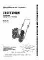
Owner's
®
120 VOLT
2500 WATT
AC
RATO
MODEL
NO.
580.327750
LU
a
0
08
_03
0
r_
,o
o_
o_,_
z__=_
z
(.9LLI.....
-4"--m
OOj_
o
m
GENERATOR
CUSTOMER
HELPLINE
1_800-222-3136
CAUTION:
Before using this
product, read this manual and
follow all Safety Rules and
Operating Instructions.
HOURS:
SEARS.
Part r',lo.B2418
ROEBUCK
REV._3/12/98
Mon. - Fri. 8 a.m. to 5 p.m. (CST)
and
CO.,
Hoffman
Estates,
IL 60179
U.S.A.
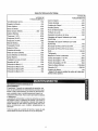
SAFETYRULES..............
INSIDECOVER
MAINTENANCE
AGREEMENT.................
10
PRODUCT
SPECIFICATIONS..............
10
WARRANTY
............................
2
OPERATION
.........................
4-9
MAINTENANCE
........................
9-12
LIMITED
SERVICE
ANDADJUSTMENTS ..........
12-13
SERVICE
RECOMMENDATIONS
...........
12
TROUBLESHOOTING
POINTS .............
14
WIRINGDIAGRAM ......................
15
REPAIRPARTS......................
16-37
EMISSIONSWARRANTY
................
38-39
PARTS
ORDERING.............
BACKCOVER
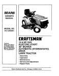
ONE YEAR WARRANTY
CRAFTSMAN
GENERATORS
SEARS warrants to the original purchaser that the alternator and engine for its portable generator will be free from
defects in materials or'workmanship for the items and period set forth below from the date of original purchase, this
warranty is not trasnferable.
CONSUMER*
Alternator
Engine
1 year'
1 year
COMMERCIAL*
90 Days
90 Days
NOTE: For the purpose of this warranty "Consumer Use" means personal residential household and emergency use
by original purchaser, not to be used as a primary source of power: "Commercial Use" means all other uses, including rental, construction, commercial, primary source of residential household power and income producing purposes°
Once a generator has experienced commercial use, it shall thereafter be considered a commercial use generator for
the purpose of this warranty.
During said warranty period, SEARS wit!, at its option, repair or replace any part which, upon examinations by
SEARS, is found to be defective under normal use and service_** Starting batteries and expendable items such as
spark plugs and air filters, which become worn during normal use are not warranted by SEARS. All transportation
costs under warranty, including return to the factory if necessary, are to be borne by the pruchaser and prepaid by
him° This warranty does not cover normal maintenance and service and does not apply to a generator set, alternator
or engine, or parts which have been subjected to improper or unauthorized installation or alteration, misuse, negligence, accident, overloading, overspeeding, improper maintenance, repair or storage so as, in SEAR's judgment, to
adversely affect its performance and reliability°
**NORMAL WEAR: As with all mechanical devices, engines need periodic parts service and replacement to perform
well. This warranty will not cover repair when normal use has exhausted the life of a part or engine,.
THERE tS NO OTHER EXPRESS WARRANTY. SEARS HEREBY DISCLAIMS ANY AND ALL IMPLIED WARRANTIES, INCLUDING BUT NOT LIMITED TO THOSE OF MERCHANTABILITY AND FITNESS FOR A PARTICULAR
PURPOSE TO THE EXTENT PERMITTED BY LAW° THE DURATION OF ANY IMPLIED WARRANTIES WHICH
CANNOT BE DISCLAIMED IS LIMITED TO THE TIME PERIOD AS SPECIFIED IN THE EXPRESS WARRANTY.
LIABILITY FOR CONSEQUENTIAL, INCIDENTAL, OR SPECIAL DAMAGES UNDER ANY AND ALL WARRANTIES
IS EXCLUDED° Some states do not allow limitations on how long an implied warranty lasts, or the exclusion or limitation of incidental or' consequential damages, so the above limitations or' exclusions may not apply to you_ This warranty gives you specific legal rights and you may also have other rights, which vary from state to state.
For service, see your nearest SEARS authorized warranty service facility. Warranty service can be performed only by
a SEARS authorized service facility° This warranty will not apply to service at any other facility° At the time of requesting warranty service, evidence of original purchase date must be presented.
SEARS, ROEBUCK and CO., Hoffman Estates, IL 60719 U.S.A.
2
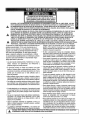
CAUTION:ALWAYSDISCONNECTSPARKPLUGWIRE AND PLACEWIRE WHEREIT CANNOTCONTACTSPARKPLUG,TO PREVENTACCIDENTALSTARTINGWHEN SETTINGUP,
TRANSPORTING,ADJUSTING,ORMAKING REPAIRSTO YOUR GENERATOR
F_
IMPORTANT
THIS GENERATOR
IS DESIGNEDFOROUTDOORUSE ONLY.USINGTHIS GENERATORINSIDEANY BUILDING OR ENCLOSURE,
INCLUDINGTHE GENERATOR
COMPARTMENTOFA RECREATIONALVEHICLE(RV), IS DANGEROUS,FIREOR AN EXPLOSIONMAY
RESULT.NOUSERPERFORMEDMODIFICATIONS,INCLUDINGVENTINGOF EXHAUSTAND!OR COOLINGVENTILATION,WILL ELiMINATETHE DANGER°
•
If this unit is usedfor backup power in the event of a utility
•
Never add fuel whileunit is running
powerfailure, take the following steps: BEFORECONNECT°
Do not overfill the fuel tank. Always allow room for fuel
INGTHE GENERATOR
TOAN ELECTRICALSYSTEM,OPEN
expansion. If tank is overfilled, fuel can overflow onto a hot
THE MAIN CIRCUITBREAKEROR MAIN SWITCHSERVICengine and cause FIREor an EXPLOSION..
INGTHE SYSTEMTO ISOLATETHE GENERATORFROM
•
Drain all gasoline from tank before transporting your generTHE ELECTRICUTILITY.FAILURETO ISOLATETHE GENERator inside your car or other vehicle.
ATORAND UTILITYSYSTEMSMAY RESULTIN DAMAGE
,
Never store generator with fuel in tank where gasoline
TO THEGENERATOR
AND MAYALSO RESULTIN INJURY
vapors might reach an open flame or spark or pilot light (as
ORDEATHTO ELECTRICUTILITYWORKERSDUETO
on a furnace, water heater or clothes dryer). FIREor AN
BACKFEEDOFELECTRICALENERGY.
EXPLOSIONmight resulL
•
This generator produces dangerously high voltage that can
•
Allow at least 2 feet of clearance on all sides of generator,
causeextremely hazardouselectrical shock.. Avoid contact
even while operating unit outdoors, or you could damage
the unit..
with bare wires, terminals, etc. Never permit any unqualified
person to operateor service the generator.
•
Generatorexhaust gases contain DEADLYcarbon monoxide
DONOToperatethis equipment in the rain, while standing
gas_This dangerous gas, if breathed in sufficient concentrain water,while barefoot, or while hands or feet are wet..Dantions, can cause unconsciousness or even death_Operate
gerous electricalshock will result.
this equipment outdoors only in the open air where ade,
The National ElectricCode requires the frame and external
quate ventilation is available.
electrically conductive parts of the generator be properly
•
Do not insert any object through cooling slots of the engineconnectedto an approvedearth ground° Local electrical
generator°You coulddamage the unit or injure yourself.
codes may also require proper grounding of the generator°
•
DONOT attempt to change the engine governed speed. FacConsult with a local electrician for grounding requirements
tory settings are correct when you receive the unit..Excesin your area.
sively high engine speeds may result in injury or damageto
equipment.
o
DONOT usethe unit if it has been damaged..Repair or
replace all damaged or defective components before you
Theengineexhaustfromthisproductcontainschemicals
run the unit.
knowntotheStateofCalifornia
to causecancer,bidh defects H
•
Do not permit childrento operate or service the unit..
=
Gasolineis highly FLAMMABLEand its vaporsare EXPLOSIVE. Do not permit smoking, open flames, sparks or heat
in the vicinity while handling gasoline..Avoid spilling gasoline on a hot engine..Comply with alt laws regulating storage
and handling or gasoline_.
,t_
LOOK
IT
MEANS
FOR "ATTENTION!!!
THIS SYMBOL
Readyour Owner's Manual carefully..Only persons who are
familiar with these safety rules and have been properly
instructed in the use of this product should be permitted to
use the product.,
Note:Inthe Stateof Californiaa sparkarrestor is requiredbylaw(Section 4442 of the CaliforniaPublicResourcesCode).,
Otherstatesmay
havesimilar taws_Federallaws applyon federa!lands,
BECOME
TO POINT ALERT!!!
OUT IMPORTANT
YOUR SAFETY
SAFETY IS INVOLVED!!!"
PRECAUTIONS.
3
TO REMOVE GENERATOR
Your AC generator was completely assernsble at the factory. It is ready for use after it has been properly serviced
with the recommended lubricating oil and fuel.,
Q
°
°
IF YOU HAVE ANY PROBLEMS WITH THE ASSEMBLY
OF YOUR GENERATOR, PLEASE CALL THE GENERATOR HELPLINE AT 1-800_222-3136.
°
IMPORTANT: ANY ATTEMPT TO RUN THE ENGINE
BEFORE tT HAS BEEN SERVICED WITH THE RECOMMENDED OIL WILL RESULT IN AN ENGINE FAILURE..
CORD SETS AND CONNECTOR
FROM CARTON
Set the carton on a flat rigid surface with "THIS SIDE
UP" arrows pointing upward.
Carefully open the top flaps of shipping carton_
Cut down corners at one end of shipping carton and
lay that side of carton down flat.
Remove packing material, carton fillers, etc_.
Remove the generator from the shipping carton°
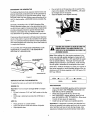
TO ADJUST HANDLE GUIDE
Your generator is equipped with a wheel kit for easy manueveringo After' you remove the generator from the carton
Lifthandle into upright position and push the black slides
down to hold the handle in position. The handle may be
lowered for easier' storage.
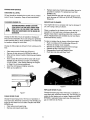
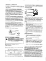
PLUGS
120 VOLT CORD SETS
CAUTION:Althougheach receptacleis rated for 120
voltsat 20 amps(2400 watts or 2A KW), the generator
use only high quality, wefl-insutated, extension cords with
the generator's 120-volt type electrical receptacle&
is rated the
for wattage
a total ofcapacityof
2500 watts.
Poweringloadsthat
exceed
the
generatorcan damage it or causeserious injuries. The total loadswith
120 volts powered thoughthese receptaclesshouldnot
exceed20 amps.
Each receptacle of this pair is protected against overload
by a single 20-amp push-to-reset type of circuit breaker°
Use each receptacle to operate 120 volts, single phase
60 Hz, A C electrical loads requiring up to 2400 watts (2.4
kW) at 20 amps of current_
Keep extension cords as short as possible, preferably
less than 15 feet long to prevent voltage drop and possibly overheating of wires.
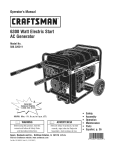
12 VOLTS DC 10 AMP BATTERY CHARGE OUTLET
!
Figure-1
Figure-2
Check the ratings of all extension cords before you use
them Extension cord sets used should be rated 125 volts
The 12 VOLT DC outlet has a unique configuration that
will only allow the 12 volt wire harness to be inserted,
When the 12 volt harness is properly inserted the red wire
wil! be positive 12 volts and the blackwire will be negative_
DO NOT modify any plug to make it fit this outlet or damage to the generator may result.
at 20 AC amps or greater' for' most electrical devices..
Some devices, however, may not require this type of
extension cord° Check the owner's manual of those
devices for the manufacturer's recommendations.
4
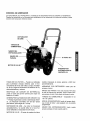
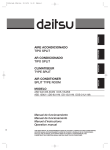
KNOW YOUR GENERATOR
Read the owner's manual and safety rules before operating your generator. Compare the illustrations with your Generator to familiarize yourself with the locations of various controls and adjustments. Save this manual for future reference_
GUIDE HANDLE
HEAT SHIELD AND
MUFFLER
AIR CLEANER
GAS CAP
CHOKE
ON/OFFLEVEL
5 HP ENGINE
CIRCUIT BREAKERS,
BATTERY CHARGE
RECEPTACLE, AND
DUPLEX RECEPTACLE
OIL FILL
OIL DRAIN
120 VOLT RECEPTACLES. May be used to supply electrical power for the operation of 120 volts at 20 amps AC,
single phase, 60 Hz,.This may be used for AC electrical
lighting, appliance, tool and motor loads.
FUEL TANK. Tank holds 18 quarts of unleaded gasoline.
SPARK ARRESTOR MUFFLER. Exhaust muffler lowers
engine noise and is equipped with a spark arrestor
screen°
BATTERY CHARGE RECEPTACLE. May be used to
supply electrical power to charge 12 volt batteries.
CHOKE SWITCH. Used when starting a cold engine.
HOW TO USE YOUR GENERATOR.
CIRCUIT BREAKERS (AC and DC), Each receptacle is
provided with a circuit breaker to protect the generator
against electrical overload° Breakers are "push to reset"
type
AIR CLEANER.
IF YOU HAVE ANY
PROBLEMS operating your Generator, please call the
Generator helpline at 1-800-222-3136.
Filters intake air as it is drawn into the
engine
5.0 H.P. HONDA ENGINE. Provides the power needed to
generate 2500 watts of AC output,
RECOIL STARTER. Used for starting the engine,
ON/OFF LEVER. Set this lever to "ON" before using
recoil starter Set lever to "OFF" to switch engine off.
Located on the engine block.
5
•
GROUNDING THE GENERATOR
The National Electrical Code requires that the frame and
external electrically conductive parts of this generator by
properly connected to an approved earth ground. Local
electrical codes may also require proper grounding of the
unit. For that purpose, a GROUND LUG is provided (Figure-3).,
o
Pour oil into the oil fill opening until oil reaches FULL
mark on the dipstick. DO NOT OVERFILL. Oii capacity of engine is 0.61 US quarts.
Install oil dipstick, hand tighten securely
Generally, connecting a No. 12 AWG (American Wire
Gauge) stranded copper wire to the grounding lug and to
an earth-driven copper or brass grounding rod (electrode)
provides adequate protection against electrical shock.
However, tocaf codes may very widely. Consult with a
local electrician for grounding requirements in your area.
Proper grounding of generator will help prevent electricat
shock in the event of a ground fault condition in the generator or in connected electrical devices. Proper grounding
also helps dissipate static electricity, which often builds up
in ungrounded devices.,
Figure-4
CAUTION:ANY ATTEMPTTO CRANKOR STARTTHE
ENGINEBEFOREIT HAS BEENPROPERLYSERVICEDWITH THE RECOMMENDEDOIL RESULTSIN
AN ENGINEFAILURE.
IF YOU HAVE ANY PROBLEMS OPERATING YOUR
GENERATOR, PLEASE CALL THE GENERATOR
HELPLINE AT 1-800-222-3136.,
Note: When adding oil to the engine crankcase in the
future, use only high quality detergent oit rated with API
service classification SF, SG, or SH rated SAE 30 weighL
Use no special additives. Although multi-viscosity oils
(5W30) improve starting in cold weather, multi-viscosity
oils will result in increased oil consumption when used
t_12 AWG STRANDEO
above 32 ° E It will be necessary to check "yourengine oil
level more frequently to avoid possible damage from running low on oil Oil sump capacity is 0.61 US quarts. DO
NOT use 10W-40.
GROUNDING
ROD
FLgure-3
colder
BEFORE STARTING THE GENERATOR
._
32 ° _LI=.5W30
warmer
SAE30
To operatethe engtne youwill need to do the following:
ENGINE OIL,
ADD GASOLINE
Important: To avoid engine damage never run engine
unless:
•
•
•
Oil level is between =Full" and "Add" marks on the dipstick,.
Oil fill plug is tightened securely into oi! fill tube or
hole.
°
Use regular UNLEADED gasoline with the Generator
engine. DO NOT USE PREMIUM GASOLINE. DO
NOT MIX OIL WITH GASOLINE°
Clean area around fuel fill cap, remove cap°
Add "UNLEADED" regular gasoline, slowly to fuel
tank. BE CAREFUL NOT TO OVERFILL° Allow about
1/4-inch of tank space for expansion.
tnstafl fuel cap and wipe up any spilted gasoline.
ADD OIL
•
•
•
•
Important: It is important to prevent gum deposits from
forming in essential fuel system parts such as the carburetor, fuel filter, fuei hose or tank during storage. Also,
experience indicates that alcohol-blended fuels (catled
Place generator on a level surface.
Clean area around oil fill and remove oil dipstick.
Wipe dipstick clean,.
gasohol,ethanolor methanol)
canattractmoisture
which
leadstoseparation
andformationofacidsduringstorage..
Acidicgascandamagethefuelsystemofanengine
whileinstorage.Toavoidengineproblems
whenusing
gasohoI,
emptythefuelsystembeforestorage
of 30 days
or longer., See "Storage" on Page 13. Never use engine or
carburetor cleaner products in the fuel tank or permanent
damage may occur.
NOTE: DO NOT USE GASOLINE CONTAINING METHANOL (WOOD ALCOHOL). You can use gasolines containing 10% ethanol or grain alcohol See "Storage" for more
information°
CAUTION:DO NOTOVERFILLTHE FUELTANK.
ALWAYSALLOWROOM FORFUELEXPANSION.
o
o
.
Pul! engine CHOKE LEVER (Figure-6) to "Full
Choke Position",.
Grasp start grip and pull slowly until you feel some
resistance., Then pull cord out with rapid full arm
stroke. Let rope return slowly. Do not let rope "snap
back" against the starter grip.
When engine starts, move choke lever to "1/2 Choke
Position until the engine runs smoothly and then to
"No Choke Position". if engine falters, move choke
lever to' "112 Choke Position" until the engine runs
smoothly and then to "No Choke Position"..
Note: If engine fails to start after 3 pulls, move the coke
lever to "No Choke Position" and pull starter rope again.
Note: If engine fires, but does not continue to run, move
choke lever to "Full Choke Position" and repeat starting
instructions..
WARNING:NEVERFILL FUELTANKINDOORS.
NEVERFILL FUELTANKWHENENGINEIS RUNNINGOR HOT,DONOT LIGHTA CIGARETOR
SMOKEWHENFILLING FUELTANK.
TO START THE ENGINE
WARNING:NEVERSTART,OR STOP,THE
ENGINE-GENERATOR
WITH ELECTRICAL
LOADS
CONNECTED
TOTHE RECEPTACLES
WITH THE
CONNECTED
DEVICESTURNEDON.
Figure-6
CONNECTING
o
•
°
•
°
o
Figure-5
•
°
Unplug all electrical loads from generator receptacles
before starting the engine_ NEVER start or stop
engine with electrical devices plugged into the panel
receptacles and turned on.
Set ON/OFF LEVER to ON (Figure-5).
ELECTRICAL
LOADS
Let engine stabilize and warm up for a few minutes
after starting..
Use this generator to operate 120 volt, single phase,
60 Hz, AC lighting, appliance, tool and motor loads,.
DO NOT connect 240 volts to 120 voIts duplex receptacles.
DO NOT connect 3-phase loads to panel receptacles.
DO NOT connect any 50 Hz loads to the generator.
Plug in and turn on the desired 120 volts single
phase, 60 HZ, AC electrical loads. DO NOT OVERLOAD THE GENERATOR Add up the rated watts (or
amps) of all loads to be connected at one time.. This
total should not be greater than the rated wattage/
amperage capacity of the generator. See "Do Not
Overload the Generator" on Page 8.
STOPPING THE ENGINE
°
•
•
Unplug all electrical loads from generator panel
receptacles° Never start or"stop engine with electrical
devices plugged in and turned on.
Let engine run at no-load for' several minutes to stabilize the internal temperatures of engine and generatort
Move On/Off Switch to Off position.
CHARGING A BATTERY
Your generator has the capability of recharging a discharged, 12-volt automotive or utility style storage battery°
Do not use the unit to charge any 6-volt batteries° Do not
use the unit to crank an engine having a discharged battery To recharge 12-volt batteries, proceed as follows:
°
Check fluid level in all battery cells.. If necessary, add
ONLY distilled water to cover separators in battery
cells. DO NOT USE TAP WATER.
•
°
°
•
if the battery is equipped with vent caps, make sure
they are installed and are tight.
If necessary, clean battery posts or terminals°
Connect battery charge cable connector' plug to panel
receptacle (Figure-2, Page 4) identified by the words
"12-VOLT DoC."
Connect battery charge cable clamp with red handle
to battery post or terminal indicated by a POSITIVE,
itsetf and the fuel tank has enough gasoline, check
engine oil level.
INITIAL STARTUP
A delay in the shutdown system allows oil pressure to
build during starting., The delay allows the engine to run
for about 10 seconds before sensing oil pressure.
RESTARTING
If you try to restart the engine within 5 second after it
shuts dowrY, the engine may not start_ The system needs
5 to 10 seconds to reseL
If you do restart the engine after such a shutdown
and have not corrected the low oil pressure, the
engine runs for about 10 seconds as described above
and then stops.
DON'T OVERLOAD THE GENERATOR
Overloading a generator in excess of its rated wattage
capacity can result in damage to the generator and to
connected electrical devices. Observe the following, to
prevent overloading the unit:
= Add up the total 'wattage of afl electrical devices to be
connected at one time° This total should NOT be
=
POS, or (+).
°
Connect battery charge cable clamp with black han" die to battery post or terminal indicated by a NEGATIVE, NEG, or (-).
•
Start engine (see "Starting the Engine" on Page 7).
Let the engine run while battery recharges.
,
When battery has charged, shut down engine (see
"Stopping the Engine" above).
Note: Use an automotive hydrometer to test battery state
of charge and condition_ Follow the hydrometer manufacturer's instructions carefully. Generally, a battery is con*
sidered to be at 100% state of charge when specific
gravity of its fluid (as measured by hydrometer) is 1o260.
LOW OIL PRESSURE SHUTDOWN SYSTEM
The engine is equipped with a low oil pressure sensor
that shuts down the engine autornaticaIly when the oil
pressure drops below 6 psL If the engine shuts down by
°
,
greater than the generator's wattage capacity_
The rated wattage of lights can be taken from light
bulbs. The rated wattage of tools, appliances and
motors can usually be found on a data plate or decal
affixed to the device°
if the appliance, tool or motor does not give wattage,
multiply volts times ampere rating to determine watts
(volts x amps = watts).
Some electric motors, such as induction types,
require about two and a half times more watts of
power' for starting than for running° This surge of
power lasts only a few second when starting such
motors. Make sure you allow for'this high starting
wattage when selecting electrical devices to connect
to your generator. First, figure the watts needed to
start the largest motor. Add to that figure the running
watts of all other connected loadso
The Wattage Reference Guide is provided to assist you in
determining how many items your generator' can operate
at one time.
WATTAGE REFERENCE
RUNNING
WATTS
ELECTRICALDEVICE
L_L ..._ .....
*AirConditioner
(12,000btu)
ELECTRICAL
DEVICE
LLL
RUNNING
WATTS
_
1700 ElectricSkillet
BatteryCharger
(20amp)
500
GUIDE
:;
:;
ELECTRICALDEVICE
:;:;
::
Oil FiredSpaceHeater
(85,000Btu)
400
*FurnaceFan(113HP)
1200
Oil FiredSpaceHeater
(30,000Btu)
225
1200
*PaintSprayer,
Airless(1/3 HP)
600
t000
HairDryer
ChainSaw
t200
HandDrill (1")
==
;,,.
1100
800to 1000 HandDdlf(1/2")
CoffeeMaker
...................
I250
BeltSander
CircularSaw(6 112")
RUNNING
WATTS
PaintSprayer,
Airless(handheld)
750 to 1000
1000 HandDrill(3/8")
J
Radio
..........
150
50 to 200
500
*Refrigerator
600
200
r
*Compressor(I HP)
2000 HandDrill(1/4")
250
SlowCooker
*Compressor(3/4 HP)
1800 HedgeTrimmer
450
*SubmersiblePump
(I-1/2 HP)
2800
*Compressor(i/2 HP)
1400 *JetPomp
800
*Submersible
Pump
(1 HP)
2000
1200
*SubmersiblePump
(1/2 HP)
t500
CurlingIron
700
LawnMower
"DeepFreeze
500
LightBu]b
700
SumpPump
MicrowaveOvern
700
*TableSaw(10")
DiscSander(9")
t200
EdgeTrimmer
500
...............................................................
ElectricNailGun
....
.....
*Milk Cooler
,
1100
.......
ElectricRange
(oneelement)
Television(10")
i
1200 Oil Burneron Furnace
J
,
..........
,,
1500 Oil FiredSpaceHeater
(140,000Btu)
300
600
1750to 2000
200to 500
............
WeedTrimmer
500
,
400
"Allow 2-1/2 times the Iisted watts for starting these device&
CUSTOMER
RESPONSIBILITIES
GENERAL RECOMMENDATIONS
The Owner/Operator is responsible for making sure that
all periodic maintenance tasks are completed on a timely
basis; that all discrepancies are corrected; and that the
unit is kept clean and properly stored. Never operate a
damaged or defective generator°
The warranty of the Generator does not cover items that
have been subjected to operator abuse or negligence.. To
receive full value from the warranty, operator must maintain Generator as instructed in this manual.
Some adjustments will need to be made periodically to
properly maintain your Generator.
All adjustments in the Service and Adjustments section of
this manual should be made at least once each season..
Follow the recommendations in the "Service Recommendation" Table on Page 12..
PRODUCT SPECIFICATIONS
Follow the instructions under "Maintenance"
age" sections of this Owner's Manual.
Generator Specifications
Rated Maximum Power
Rated Voltage
2500 (2.5 KW)
12 VDC and 120 Volts AC
Rated Maximum
Load Current
20.8 AC amperes
Rate Frequency
60 Hz at 3600 rpm
Phase
Single Phase
and "Stor-
NOTE: Your generator is equipped with a spark arrestor
muffler: The spark arrestor must be maintained in effective working order by the owner/operator_ In the State of
California a spark arrestor is required by law (Section
4442 of the California Public Resources Code)_ Other
states may have similar' laws. Federal laws apply on federal lands°
CAUTION:DISCONNECTSPARKPLUGWIRE
FROM SPARKPLUGANDPLACEWIRE WHEREIT
CANNOT'COMEIN CONTACIWITHYOURSPARK
PLUG BEFOREWORKINGON YOURGENERATOR.
Engine Specifications
Rated Horsepower
Spark Plug
Set Gap To:
Gasoline Capacity:
Oil (Q.61 US quarls capacity):
Solid State Ignition
Air Gap
5,0 at 3600 rpm
NGK BPR6ES
or equivalent
0.030 inch (0.76mm)
1.8 quarts
SAE 30 weight
0.0125 inch
Should you experience any problem you cannot easily
remedy, please contact your nearest Sears Service CenterJDepartment or call the 1-800 number listed on the
front of this manuat we have competent, well-trained
technicians and the proper tools to service or repair' this
unit,.
GENERATOR
MAINTENANCE
Generator maintenance consists of keeping the unit clean
and dry Operate and store the unit in a clean, dry environment where it wilt not be exposed to excessive dust,
dirt, moisture or any corrosive vapors,, Cooling air slots in
the generator must not become clogged with snow,
leaves, or any other foreign material.
Check the cleanliness of the generator frequently and
clean when dust, dirt, oi!, moisture or other foreign substances are visible on its exterior surface,.
Note: We DO NOT recommend using a garden hose to
clean the generator_ Water can enter-the engine fuel system and cause problems,, tn addition, ff water enters the
generator through cooling air slots, some of the water will
be retained in void and cracks of the rotor and stator
winding insulation, Water and dirt buildup on the generator internal windings will eventually decrease the insulation resistance of these windings°
Please read and retain tn_smanual, the instructions will
enable you to assemble and maintain your' generator
properly. Always observe the "SAFETY RULES'L
To clean the Generator:
*
°
Once a year you should clean or' replace the spark plug
and replace the air filter A new spark plug and clean air
filter assure proper fuel-air mixture and help your engine
run better and last longer
.
°
MAINTENANCE AGREEMENT
A Sears Maintenance Agreement is available on this
product,,
Use a damp cloth to wipe exterior surfaces cfean.
A soft bristle brush may be used to loosen caked on
dirt, oil, etc.
A vacuum cleaner may be used to pick up loose dirt
and debris.
Low pressure air (not to exceed 25 psi) may be used
to blow away dirt,, inspect cooling air' slots and openings on the generator,, These openings must be kept
clean and unobstructed.
CUSTOMER RESPONSIBILITIES
CAUTION:NEVERINSERTANY OBJECTORTOOL1
THROUGHTHE AIR COOLINGSLOTS,EVENIF !
THE ENGINEIS NOT RUNNING. DAMAGETO THEi
UNIT OR PERSONALINJURY MAY RESULT.
J
Read and observe the safety rules.
Follow regular schedule in maintaining, caring for and
using your generator.
10
ENGINEMAINTENANCE
°
CHECKING OIL LEVEL
Replace spark plug if electrodes are pitted, burned or
porcelain is cracked° For replacement use NGK
BPR6ES only,
Check electrode gap with wire feeler gauge and set
spark plug gap to 0.030 inch (0.76 mm) if necessary
(Figure-9).
Oii levet should be checked prior to each use or at least
every 5 hours of operation, Keep oil level maintained.
o
CHANGING ENGINE OIL
SERVICE AIR CLEANER
Your engine will not run properly and may be damaged if
you run it using a dirty" air cleaner,,
CAUTION:DISCONNECT
SPARKPLUG WIRE
FROMSPARKPLUGAND KEEPITAWAYFROM
SPARKPLUG.DO THIS EVERYTIME YOU PERFORMANY MAINTENANCEON THE ENGINEOR
GENERATOR
Clean or replace the air cleaner once every 125 hours of
operation or once each year, whichever comes first.
Replace more often if operating under dirty or dusty conditionso Replacements are available at your local Sears
Authorized Service Center.
Change oil after first 2 hours of operation, Change oil
every 25 hours thereafter., tf you are using your generator
under extremely dirty or dusty conditions, or in extremely
hot weather, change oil more often,
To
°
=
°
=
°
o
Change oil while engine is still warm from running, as follows:
o
o
o
°
•
•
Clean area around oil drain plug (Figure-7).
Remove oil drain plug and oil fill plug to drain oil.
When oil has drained, install oil drain plug and tighten
securely°
Insert a clean fill funnel and fill oil sump with recommended oil until oil level is at point of overflowing.
POUR SLOWLY. (See "Before Starting the Engine"
on Page 6 for oil recommendations).,
Install the oil fill plug and tighten securely,
Wipe up any spilled oilo
clean or replace the air cleaner, follow these steps:
Push in on tabs and lift outside edge (Figure-8),
Remove air cleaner cover carefully°
Remove the air filter and examine it for damage,
Replace air filter if damaged or dirty.
Reassemble all parts and replace cover_,
Push tabs into slots until they %lick"o
Figure_8
REPLACE SPARK PLUG
Change the spark plug every 100 hours or operation or
once each year, whichever comes first. This will help your
engine to start easier and run better° Replace with NGK
BPR6ES or equivalent type spark plug, Set spark plug
gap to 0.030 inch (0,76mm)_
F}gure-7
CLEAN SPARK PLUG
Change the spark plug every 100 hours of operation or
once each year, whichever comes first. This will help your
engine to start easier and run better. Replace with NGK
BPR6ES only,
.
Clean area around spark plug,
°
Remove and inspect spark plug.
11
The engine exhaust muffler has a spark arrestor screen+
Inspect and clean the screen every 25 hours of operation
or once each year, whichever' comes first.
0030" FEELER GAUGE
(O,,76mm)
NOTE: If you use your' generator on any forest-covered,
brush-covered or grass-covered unimproved land, it must
have a spark anestor.. The spark arrestor must be maintained in good condition by the ownedoperator+
•
Clean and inspect the spark arrestor as follows:
•
To remove the heat shield from the muffler (Figure-3),
remove the three bolts that connect the shield to the
muffler.
°
Remove the phillips head screw that attaches the
spark arrestor screen.
•
Pull screen straight ouL
°
Inspect screen and replace if torn, perforated or otherwise damaged+ DO NOT USE a defective screen. If
the screen is not damaged, clean it with a commercial
solvent.
°
Reattach the screen and the heat shield.
Figure-9
CLEAN SPARK ARRESTOR
SCREEN
WARNING: LETTHE MUFFLERCOOLBEFORE
WORKINGON IT+CONTACTWITH A HOT MUFFLEROR ENGINECANCAUSESEVEREBURNS+
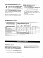
SERVICE RECOMMENDATIONS
Fill in DatesAsYouCompleteRegular
Service
HOURLY
OPERATING
INTERVAL
SERVICE
DATES
MAINTENANCE
TASK
ENGINE
Check011Level
Before
EachUse
Every25
Hoursor
Yearly
Every50
Hoursor
Yearly
Every100
Hoursor
Yearly
X
................................
ChangeEngineOil*
,
............
:
ServiceAir+Cleaner
i, .........
L
L
....
X***
C{eardReplaceSparkPlug
PrepareForStorage
.............
X**
X
Prepareunitfor storageif _tisto remainidle for MORE
THAN30 DAYS
"Change oil after first 2 hours of operation, then after every 2 hours,
** Change sooner when operating under heavy Goador high ambient
temperature
"*'Clean more often under dirty or dusty conditions
ENGINE SPEED
•
Your generator engine runs at a constant speed+ This
constant operating speed is maintained by a mechanical,
flyweight type, fixed speed governor+ DO NOT try to
adjust the governed speed setting for' the following reasons:
°
•
t2
High engine speeds are dangerous and increase the
risk of personal injury or damage to equipment+
Low engine speeds impose a heavy load on the
engine when sufficient engine power' is not available
and may shorten engine f_fe+
The generator will supply correct rated AC frequency
and voltage only at the proper speed+ Some con-
nectedelectrical
devicescouldbedamaged
by incorrectfrequency
and/orvoltage
ADJUSTING THE CARBURETOR
The carburetor of your generator is preset at the factory_
DO NOT TAMPER WITH THE CARBURETOR as this wilt
void the warranty for the emission control system. If you
think your carburetor needs adjusting, see your nearest
Sears Service dealer If your generator is to be used at
an elevation above 5,000 feet in attitude, consult with a
Sears Authorized Service Facility regarding high altitude
jetting changes. To improve engine performance, see
your nearest Sears Service dealer_
Honda uses lean carburetor settings and other systems to
reduce the emissions of carbon monoxide, oxides of nitrogen, and hydrocarbons.
The U.S. and California Clean Air Acts. EPA and California regulations require all manufacturers to furnish written instructions describing the operation and
maintenance of emission control systems,
Tampering and Altering. Tampering with or altering the
emission control system may increase emissions beyond
the legal limit. Among those acts that constitute tampering are:
o Removal or alteration of any part of the intake, fuel, or
exhaust systems
° Altering or defeating the governor linkage or speed
adjusting mechanism to cause to engine to operate
outside its design parameters.
EMISSION CONTROL SYSTEM INFORMATION
Sources of Emissions. The combustion process produces carbon monoxide, oxides of nitrogen, and hydro.
carbons Control of hydrocarbons and oxides of nitrogen
is very important because, under certain conditions, they
react to form photochemical smog when subjected to
sunlight. Carbon monoxide does not react in the same
way but it is toxic°
Problems that may Affect Emissions. If you are aware
of any of the following symptons, have your engine
inspected and repaired by you servicing dealer.
= Hard starting or stalling after starting
*
Rough idle.
o Misfiring or backfiring under load
o Afterburning (backfidng)
GENERAL
To avoid engine problems, the fuel system should be
emptied before storage or 30 days or longer. Fo]low these
instructions
The generator should be started at least once every
seven days and allowed to run at least 30 minutes_ If this
cannot be done and you must store the unit for more than
30 days, use the following information as a guide to prepare it for storage.
PROTECT FUEL SYSTEM:
Remove all gasoline from the fuel tank to prevent
gum deposits from forming on these parts and causing possible malfunction of engine
Run engine until engine stops from lack of fuel
WARNING:NEVERSTOREENGINEWITH FUELiN
THETANK INDOORSOR IN ENCLOSED,POORLY
VEHTILATEDAREAS,WHEREFUMESCAN
REACHAN OPENFLAMESPARKORPILOTLIGHT
ASON A FURNACE,WATERHEATER,CLOTHES
DRYEROR OTHERGASFURNACE.
WARNING:DRAINFUELINTO APPROVEDCONTAINEROUTDOORS,AWAYFROM OPENFLAME
BESURE ENGINEIS COOL°
LONG TERM STORAGE INSTRUCTIONS
CHANGE OIL:
It is important to prevent gum deposffs from forming in
essential fuel system parts such as the carburetor, fuel filter, fuel hose or tank during storage Experience indicates
that alcohol-blended fuels (called gasohol, ethanol or
methanol) can attract moisture which leads to separation
and formation of acids during storage. Acidic gas can
damage the fuel system of an engine while in storage_
While engine is still warm, drain oil from crankcase. Refill
with recommended grade
OIL CYLINDER BORE:
•
13
Remove spark plug and pour about 1/2 ounce (15 ml)
of engine oil into the cylinder Cover spark plug hote
with rag Crank slowly to distribute oil
Install spark plugo Do not connect spark plug wire
CAUTION:AVOIDSPRAYFROMSPARKPLUG
HOLEWHEN CRANKINGENGINESLOWLY,
J
°
o
sible, store your unit indoors and cover it to give protection from dust and dirt. BE SURE TO EMPTY THE
FUEL TANK.
Cover your unit with a suitable protective cover that
does not retain moisture°
Store generator' in a clean, dry area..
GENERATOR:
o
•
DANGER:STORAGECOVERIS FLAMMABLE,DO
NOT PLACETHE STORAGECOVEROVERA HOT
GENERATOR°LE'I"THE UNIT COOLFOR A SUFFICIENTTIME BEFOREPLACINGTHE COVERON
THE UNIT. IF YOU PLACETHE COVERONTHE
UNIT BEFORETHE GENERATOR
IS COOL,THE
COVERCOULDSTARTFIRE,
Clean the generator' as outlined on Page 11 to ("To
Clean the Generator'S,.
Check that cooling air' slots and openings on generator are open and unobstructed,
OTHER STORAGE TIPS:
°
•
Do not store gasoline from one season to another.
Replace your gasoline can if it starts to rusL Rust
and/or dirt in you gasoline will cause problems, if pos-
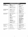
PROBLEM
CAUSE
CORRECTION
Engine is running,but
no AC output is available
I11
2.
3_
4_
One of ille circuit breakers is open.
Fault in generator:,
Poor connection or defective cord set_
Connecteddevice is bad,
1_
2.
3.
4o
Reset circuitbreaker.
contactSears Service Facility.
Check and repair:
Connect a device that is in good condition
Engine runsgood at noload but "bogs down"
when loads are connectedo
1.,
2.
3.
4.
Short circuit in a connectedload.
Enginespeed is too slow.
Generatoris overloaded,,
Shorted generatorcircuit,
1.
2.
3,
4.
Disconnect shorted electrical load_
Contact Sears Service Facility,,
See "Don't Overload the Generator",
Contact Sears Service Facility_
Engine will not start; or
starts and runs rough,
1.
2,
3.
4,,
5,
6.
7,
8,
9o
10_
11,
12_
On!OffSwitch set to Off.
Dirty air cleaner,
Out of gasoline,
Stalegasoline,
Spark plug wire not connected to spark plug.
Bad spark plug_
Water in gasoline,,
Overchoking
Low oi! level.
Excessivelyrich fuel mixture,
intake valve stuck open or closed,
Engine has lost compression.
1o Setswitch to ON,
2.. Cleanor replace air-cteaner:o
3. Fill fuel tank_
4. Drain gas tank; fill with fresh fuel.
5. Connect wire to spark plug,.
6. Replace spark plug.
7. Drain gas tank; fill with fresh fuel.
8, Open choke fully and crank engine.
9,. Fill crankcase to proper level
!0. Contact Sears Service Facility,
11_,Contact Sears Service Facility.
12. Contact Sears Service Facility,
Engineshuts down during operation_
1. Out of gasoline_
2,, Low oit level
1,, Fill fuel tank,
2_ Fill crankcase to proper level
Enginelacks power_
1o Load is too high,,
2_ Dirty air filter,_
1.
2.
Engine "hunts" or falters
1,, Choke is opened too soon,
2,. Carburetor is running too rich or too lean,
1_, Move choke to halfway position until engine
runs smoothly,,
2. Contact Sears Service Facifity_
14
See "Don't Overload the Generator"
Replace air filter:
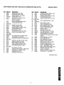
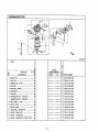
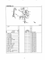
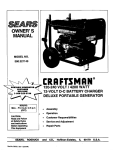
CRAFTSMAN
2500 WATT DELUXE
AC GENERATOR
580.327750
<1:
1
u_
e,/
03
i
!=
q.
u
=i--k r=-t=_"l
-=
L;
O3
Drawing No., B2420
15
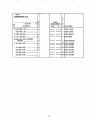
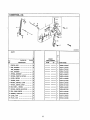
CRAFTSMAN
2500 WATT DELUXE
AC GENERATOR
580.327750
REPAIR PARTS
.,,.o
o3
o3
o
O3
If)
_J
o3
L--
\
!6
7
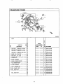
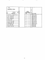
CRAFTSMAN
2500 WATT DELUXE
AC GENERATOR
_ESCRIPTION
HONDAGC1605 HP (t RE&)
BASEAND AXLEASM (1 REQ..)
VIBRATIONMOUNT- ALT (2 REQ)
GROUNDW1RE{I REQ.)
SELFDRILLER1244 X 7/8 {1 REQ.)
SCREW,PANHD. MACH
M4-&7 X 10 (2 REQ.)
MOUNT,VIBRATION-ENGINE(2 REQ)
LOCKWASHER-MS(6 REQo)
t
2
3
4
5
6
B2392
B2406
85652
143-5362I
B2153
75475
7
8
9
10
11
t2
!3
14
15
16
17
18
19
20
21
22
23
24
25
26
27
28
29
30
31
32
33
85651
22129
(NOTUSED)
WASHER,FLAT_8 (2 REQ.)
38150
STATORASSEMBLY(1 REQ.)
82413J
HOUSING,ENGINEADAPTOR(1 REQ)
66365
ROTORASSEMBLY(t RE&)
91820J
BEARING,BALL (1 REQ.,)
65791
BOLT,ROTOR-5116"-24X 6 25 (1 REQ,)
24420
CARRIER,REARBEARING(i REQo)
668258
(NOTUSED)
(NOTUSED)
BOLT,STATOR
M6-1.,00
X 85 MM (4 REQ,)
86308D
LOCKWASHER
- NO8(2 REQ)
22264
SCREW(TAPTITE)
M5-&80X 16MM (2 REQ.,)
66849
(NOTUSED)
RECEPTACLE
120-VOLTSAC, 20A (1 REQ.)
68759
BREAKER,ClRCUIT-20A(i REQ.)
77247
PANEL,CONTROL2AKW (1 REOo)
B2424
BRUSH & BRIDGERECTIFIER(1 REQ..)
91825
FLATWASHER-(SPECIAL}(1 REQ)
67451
(NOTUSED)
NUT,HEX-M4-O..7(2 REQ,)
51715
SCREW(TAPTITE)-M5-O.80
X t0 MM (4 REQ.)
74908
SCREW,M6-I nOX 16 WING (1 REQ)
86494
GROMMETRBC (2 REQ.)
84242
CAPSCR_Ai,HE)(HD (4 REQ.)
86307
580.327750
REPAIR
PARTS
ITEM PARTNO..
DESCRIPTION
34
35
36
37
38
67022
45771
26850
22145
22769
GROMMET,BEARINGCARRIER (1 REQ
M8-125 HEX NUT (6 REQ)
WASHER,SHAKE PROOF#10 (1 REO.)
FLATWASHER-M8 (4 REQ.)
WASHER,SHAKE PROOF#10 (1 REQ)
39- 44
45
46
47
48
49
50
51
52
53
54
55
57
58
(NOTUSED)
93639
(NOT USED)
B2517
82419
B2415
B2518
46476
82347
51767
82395B
B2395A
27007
39253
DECAL,DANGER-ENGLISH(1 REQ)
DECAL,RECOIL(1 REQ)
DECAL,CRAFTSMAN(1 REQ..)
DECAL,CONTROLPANEL(1 REQ_)
DECAL,ENGINESHROUD(I REQ)
CAPLUG 1" SQUARE(2 REQ,)
ENDCAP (2 REQ,)
HHOS,M6-1,,0 X 45 (2 REQ)
FOOTASM, SUPPORT LH (1 REQ,)
FOOTASM, SUPPORTR,H,.(t RE&)
VIBRATION
MOUNT,LEG(2 REQ,)
SCREW,HID{ HD. CAPSC. M8-1,,25X 20 LONG
(6 REQo)
59
60
61
62
63
64
65
66
67
68
69
70
7I
52858
B1T/9
B2857
49808
81760
75402
B2407
96409
82437
77247a
90418
65795
66849A
NUT, FLANGE-MS-125 (6 REQ..)
(;OVER, HINGE(2 REQ.)
NUT,LOCKINGM6-1o0 (2 REQ,,)
WASHER,FLAT-M12(2 REQ.)
WHEEL AND TIRE ASM 10" (2 REQ)
PUSH NUT-1t2" DIA. (2 REQ.)
HOLDER,EXTENSIONCORD(1 REQ..)
DECAL,1-800 NUMBER (1 REQ)
DECAL,STARTINSTRUCTIONS(1 REQ)
BREAKER,CIRCUIT-IOA (1 REQ.)
OUTLET,12 VDC SNAP
RECTIFIER,BATTERYCHARGE(1 REQ.)
TAPTITE,M% - 0,7 x 20 (1 RE&)
Drawing No_[32421
17
ZLe4EO600
, ,,,
,,,,,,,
GG160
Q
T
Y
G
0
Ref.
No.
_ocK NO,
ENGINE
SERIAL
P_'MBER
E-6
............
U
DESCRIFr_N
FROM
O
R
_ E
TO
Q PARTNUMBER
,,,,,,,
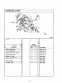
1 11300-ZL8-600
1 COVER
ASSY.t CRANKCASE
(Q-TYPE) • •
COVER
ASSY., CRANKCASE
(U-TYPE) . e!
1 111300-ZL8-660
COVER
ASSY., CRANKCASE
(UX-TYPE) •
1 11300"ZL8-670
2 GASKET,
OIL FILLERCAP ..........
ei
1 1567.5-ZE1-003
3 GAUSE
ASSY., OIL LEVEL ..........
ei
1 15650-ZL8-003
4 GOVERNOR
ASSY
..................
•
1 16510-ZLE-000
5 WEIGHT,GOVERNOR
...............
•
16511-ZL8-000
6 HOLDER,
GOVERNOR
WEIGH,.........
=
1 16512-ZL8-000
7 PINt GOVERNOR
WEIGHT............
•
2 16513-ZEI-000
B SLIDER,GOVERNOR
...............
•
1 16531rZE1-O00
1
9 SHAFT,GOVERNORARM .............
J
16541-ZL8-000
10 BOLT,FLANGE(6X25).............
•
8 90121-952--000
11 BOLT,DRAINPLUG ................
•
2 90131-883-000
1 90131-883-000
o
BOLT DRAINPLUG
0
.....
m
18
I
2 90131-896-650
't
90131-896-650
CRANKCASE COVER
I0
E-17_,
10
11
B
ZLB4EO600
GC!60
Q
T
Y
!G
ReL
No.
BLOCK
NO.
ENGINE
SERIAL
NUIVIBEB R
E-6
_
DESCRIPTION
E
FROM
TO
Q
PARTNUMBER
,,,,,,,,,,
,, ,,,,,,
,, , .,,,
12 WASHER,THRUST(6MR) ............
1 9045t-ZE1-000
13 CLIP,GBVERNORHOLDER...........
1 90602-ZE1-000
14 BEARING,RADIALBALL (67-128)
.... !a
1 91001-ZL8-003
15 OILSEAL(28X41.25X6)
...........iei
1 91202-ZLB-003
16 WASHER,PLAIN(6MM).............
2
17 WASHER,DRAINPLUG(12MR).......
94101-06800
94109-12000
94109-12000
IB PIN,LOCK(8MM).................
I 94251-08000
o!
19 PIN,DOWEL(8X20)...............
2 94301-08200
19
CRANKSHAFT
®
4
ZL34E0700
Q
T
Y
r_
ENGINE
SERIAL
NUMI_
R
E
Q
PARTNUMBER
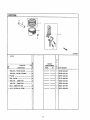
1
13310-ZLB-600
1
133I0-ZL9-600
1
13310-ZLB-650
CRANKSHAFT{OMP................
I
13310-ZL9-650
3 {RANKSHAFT{OMP. (V-TYPE) .......
1
13310-ZL8-670
CRANKSHAFTCOMP................
I
13310-ZL9-670
1
90402-ZL8-000
B.£)CK NO.
Ret,
No.
...........
E-71
6
0
DESCRIP3"r.JN
FROM
TO
,,,,,,,
1 CRANKSHAFT
COW,
P, (_TYPE)
CRANKSHAFT
C0RP...............
.......
•
2 CRANKSHAFT_0RP. (P-TYPE) ......,
4 WASHER,IHR3ST .,, .......
........
e1
20
PISTON
B
_4
6
5
ZI,,84EOBO0
G0!60
Q
T
Y
3
ReL
No.
BLOC_NO.
DESGRtFrfON
E--81
8
ENGINE
SEPJAL
NUMBER
R
FROM
Q PARTNLflVIBER
TO
--
"",:....
1 113010-ZL8-003
1 RINGSET, PISTON(RTKEN) ........
13010-ZLB-004
RINGSET,PISTON(TEIKDKU)......
2 PISTON..................
....
.. .
1 13101"ZL8-000
3 PINtPISTON ....................
1 13II!-ZE0-000
!13200-ZL8-000
4 RODASSY,, CONNECTING...........
I
RODASSY.,CONNECTING...........
t3200-ZL9-000
19000!-ZE1-000
5 BOLT,CONNECTING
ROD ............
2
6 CLIP,PISTONPIN{13MM).........
90551-ZE0-000
=
2'1
_
:
_
CAMSHAFT
2
3
)
2LB4E_900
GG160
Re[.
No.
BLO('..,,,(
NO.
G
C
1
6
O
_
DEBORIPTION
i
1 PULLEY
{0MP., CAMSHAFT
..........
q
T
Y
ENGINE
SEP-.IAL
NUMBER
FR_I
TO
R
E
Q PP_TI
_FAJ'wlBER
m
i
m
•
2 SHAFT,CAMPULLEY...............
•
14320-ZL8-000
I 14324-ZL8-000
3 BELT,TIMING{84HL_G-200) ......•
1
1_00-ZL8-'003
BELT,TIMING(79H_ G-200) ......
I
14400-ZL9-003
4 ARM,IN.VALVEROCKER...........
•
I 14431-ZL8-000
5 ARM,EX.VALVEROCKER...........
o!
I 14441-ZL8-000
6 SHAFT,ROCKERARM ...............
e:
2
? VALVE,IN......................
o_
1 14711-ZL8-000
8 VALVE,EX......................
e
1 14721-ZL8-000
9 SPRING,VALVE ..................
•
2 14751-ZL8-000
14461-ZL8-000
10 RETAINER,
IN.VALVESPRING ......•
2 14711-ZEt-000
11 SCREW,TAPPETADJ...............
ej
2 90012-333-000
12 NUT,TAPPETADJ.................
•
90206-001-000
13 O-RING(6.8X1.9)...............
o
91306-PJ4-000
22
RECOIL STARTER
1
i
9
8
ZLB4EI 100A
GC160
Ref,
No.
BLOCK NO.
DESCRIPTION
E-11
Q
T
Y
S
C
1
6
o
ENGINE
SERIAL
NUMBER
FROM
TO
R
E
Q PARTNUMBER
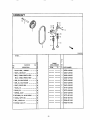
1 STARTERASSY.,RECDIL*NRI*
(BLACK)......................
o
1 28400-ZLB-OO3ZA
8KNOB, RECOILSTARTER............
e
1 28461-ZLB-O03
9 ROPE,RECOILSTARTER............
o
1 28462-ZL8-003
23
FAN COVER
,2
2
ZL_E1290
GC160
Q
T
Y
_eL
No,
BLOCKNO,,
ENGINE
SERtALNUME_ER
E-12
FROM
DESCRIPTION
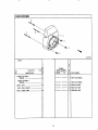
1 COVER,
FAN*NHI*
(BLACK)
(;OVER,FAN*flH1*
(BLACK)...............
..
"ffJ
R
E
Q (PARTNUMBER
t
,
19611-ZL8-000ZA
1 19611-ZL9-OOOZA
, ......
3 90043-ZL8-000
2 BOLT,STUD ......................
BOLT,STUD(FANIC) ..............
3 90041-.ZL9-000
3 NUT.,FLANGE
(6MR) ...............
3 90303-MRt-000
24
CARBURETOR
12
11
I
t5
ZLB4E1400
GCI60
Ref+
NO.
BLOCK NO.
DESGRIPTION
Q
T
Y
3
3
E-14 i
B
O
ENGINE
Sm LNUmBm R
FROM
TO
E
O PARTNUMBER
+
I GASKETSET .....................
1:16010-883-015
D
2 FLOATSET ......................
"1 16013"ZLI"003
1
D
3 C_MBERSET, FLOAT..............
16015-ZLB-O03
4 SCREWSET ......................
B
1 16016-ZGO-WO0
D
5 _CREWSET,DRAIN................
1 16024-124-760
6 SCREW
SETB .....................
1 16028-ZE0-005
7 SCREWSET ......................
I=,
1 16029-ZG0-901
8 CARBURETOR
ASSY.(BB61BB) ......O
I
CARBURETOR
ASSY.(BB63BA) ......
16100-ZL8-801
i 16100-ZL9-801
+1
O
9 VALVECOMP.,FLOAT..............
16155-ZL8-003
I 16166-ZL8-003
O
10 NOZZLE,
MAIN ...................
1
NOZZLE,
NAIN ...................
!6166-ZL9-003
11 INSULATOR,
CARBURETOR..........D
1 16211-ZL8-000
D
12 GASKET,INSULATOR..............
1 !6212-ZL8-000
D
13 GASKET,CARBURETOR.............
2
14 BASKET,CARBURETOR
(CHOKESIDE) .
i
@
25
16221-883-BO0
1622B-ZLB-O00
GC160
CARBURETOR
Cont.
Re[.
No.
BLOCKNO.
_14
DESCRIPTION
Q
T
Y
(3
O
1
6
0
ENGINE
SERIALNUMBER
FROM
TO
Ft
E
Q _P_F_rNUMBEB
15 GUIDECOMP.tAIR ................
I
19650-ZL8-000
GUIDECDMP.,AIR ................
1
19650-ZL9"000
6
16 SCREW,PAN(5X6)................
1 93500-05006-1H
@
17 CLIP,TUBE(B6.5)...............
1 95002-02650
18 BULKHOSE,VINYL (4X7X8000)
(4X7X150)....................
1 95003-07008-60E
O
(I) 99101-124-0600
1 99101-124-0600
O
19 JET,MAIN(#60) ................
JET,MAIN(#62)
(I) 99101-124-0620
O
o_oi_woa_#wto_
99101-124-0650
®
JET,MAIN(#65)
JET,MAIN(#55)
e_mw_w_mam_o
JET,MAIN(#58)
wmwP
m
(I) 99101-124-0550
_a
(I) 99101-124-0580
_wl
26
AIR CLEANER
4
ZLB4Et 5OO
=._
GC160
Re[.
No.
BOOK NO.
DESCRIPTION
G
T
Y
3
D
E-15 1
B
o
ENGINE
S_L_. NUMBER
FRO4VI
R
E
Q PARTt'&IMBER
TO
1 TUBErBREATHER
.................
1 !5721-Zt.8-000
TUBE,BREATHER
.................
1 15721-ZL9-000
2 ELERENT,
AIR CLEANER
............
t
3 HOUSINGCORP.,AIRCLEANER......
1 17220"ZL8-000
D
4 GASKET,AIRCLEANER.............
1 17228-ZL8-000
D
5 COVER,AIR CLEANER..............
1 17Z:31"ZLS-000
Z
6 BOLT,FLANGE(6X112)(CT200)....
E
27
17Zll-ZL8"000
90003-ZL8-000
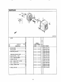
MUFFLER
2
7
9
3
7
;;_t,,,_]4.E
!_A
GC160
Q
T
Y
G
0
Refo
No.
BLOCK NO.
E_G_'qE
E_16 1
DESC_
SEPJJU_
NUMBER
6
0
r,
FROM
1 MUFFLER
COHP
...................
TO
R
E
Q PA.I:TT
N_
1 i18310-ZL8-O10
MUFFLER
CQMP
...................
1
2 PROTECTOR,
RUFFLER.............
18310-ZL9-000
1 18321-ZL8-000
1 18321-ZL8-000
PROTECTOR,
RUFFLER
(CBJ) ........
1 18321-ZLS-A00
3 ARRESTERCOMP.,
SPARK...........
e
1 18350-ZL8-000
4 PLATE,ARRESTERNUMBER
..........
o
1 18356-ZL8-000
5 SHROUD,
MUFFLER................
o
1 I%64-ZL8-000
6 BOLT,FLANGE
(6X79) (CT200) .....
o
Z
90004-ZL8-000
o
7 BOLT,FLANGE(6X12).............
3 90013-883"000
o
8 SCREW,TAPPING(4X6)............
2
3
m
9 GASKET,MUFFLER ................
90055-ZEI"_00
90055-ZE1400
(I) 18381-ZL8-305
28
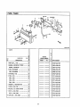
FUEL TANK
_;,..-20
6
24
27
7
6
13
!8
19
11
21
GC160
G
Ref_
No,
BLOCKNO,
DESCRIPTION
ENGINE
SERIAL
NUMBER
E-17 1
6
0
FROM
10
Q
T
Y
R
E
Q PARTNUMBER
,,,u, ,,
1PUHPASSY., FUEL................
•
1 16700-ZLB-003
2 RUBBER,SUPPORTER(107MR).......o
1 16854"ZHB-O00
RUBBER,SUPPORTER..............
1 168%'ZL9-800
3 TUBE,DIAPHRAGM................
•
1 16882-ZLB'O00
1 16882-ZL9-000
TUBE,DIAPHRAGM................
4 STRAINER,FUEL .................
=
1 16952-ZAB-BO0
5 TANK,FUEL .....................
D
I 17511-ZLBoO00
TANK,FUEL .....................
I 17511-ZL8-800
•
TANK,FUEL .....................
mb
TANK,FUEL .....................
m
,_
u
1 17511-ZL9-000
I 17511-ZL9-800
6 RUBBERB,TANKMOUNTING.........D
2
7 JDINT,FUELTUBE................
!o
I 17519-ZL8-800
8 COLLAR,FR.COVERSETTING .......
Fo
I 17535-166-000
9 STAYA, FUELTANK ...............
ie
I 17561-ZLB-O00
STAYA, FUELTANK ...............
10 CAPASSY.,FUELTANK ............
!e:
2g
17516-ZV0-000
I
17561-ZL9-000
I
17620-ZL8-003
GG160
Re[
No,
BLOCKNO.
DESCRIFr_ION
Q
T
Y
G
C
E-17 1
6
0
ENGINE
SERIALNUMBER
FROM
TO
R
E
O
PART NUMBER
,,,,,.,
11 TUBE,FUELTANK.................
1 17701-ZL8-000
12 TUBE,FUEL .....................
1 17?02-ZL8-000
13 TUBE,FUEL .....................
1
14 TUBE,FUELRETURN...............
1 17703-ZL8-800
1 17703-ZL9-801
TUBE,FUELRETURN......
.........
1 80103-MG2-000
o
15 RUBBER,
RR.FENDER..............
0
16 BOCT,STUD(FITANK).............
17702-ZLB-800
N_a
mmmm
1 90041-ZL8-000
17 WASHER(BMM) .................
_. 0
1 90473-896-000
18 COLLAR(14X6.1)................
6
2 90501-KA2-640
19 BOLT-WASHER
(6X25).............
®
2 93404-06025-00
20 SCREW-WASHER
(5X14} ............
0
2 93894-05014-00
0
21 NUT,FLANGE(6_) ...............
1 94050,06000
0
23 CLIP,TUBE(BS).................
1 95002-02080
3 95002-02080
®
1 95002-02100
0
24 CLIP,TUBE(BIO)................
3 95002-02100
®
I
25 CLIP,TUBE(C9).................
1 95002-50000
0
26 CLIP,TUBE{C11)................
1 95002-70000
27 BULKHOSE,FUEL(5,5X8000)
(5.5)(33)
.....................
®
1 95001-55008-40M
30
FLYWHEEL ® HGNR1ON COL
21..g_1tt_
GC160
Q
T
Y
Ref
No.
ENGINE
SERIALNUMBER
C
E-19 1
6
0
BLOCKNO.
DESCRIP'TK_N
FROM
R
E
Q PARTN_
TO
1 13331-357-O00-
1 KEY,,SPECIAL_OODRUFF
(25X18) ...
2 C0IL ASSY.,IGNITION ............
D
1 30500-Z_-004
3 CLAMP,STOPSWITIJH
WIRE .........
o
1 30548-ZL8o000
4 CLAMP,WIRE ....................
@
1 30549"ZL8-000
5 FLYWHEEL
C0RP
..........
. .......
1 3!110-ZL8-004
Ot
6 WIRE,STOPSWITCH...............
1 32195-ZL8-000
O
7 WIRE,STOPSWITCH...............
i
Ol
8 PROTECTOR,
SWITCH ..............
9 SWITCHCOMP.,DILLEVEL
.........ot
10 HOLDER,STOPSWITCHWIRE
........o
32195-ZL8-810
i!
35419-ZL8-000
1,
1
35480-ZL8-811
36103-ZE1-000
12 BOLT,FLANGE(6X14)............
;
2 90013-883-000
1 90014-952-000
@P
13 BOLT,FLANGE(6X28).............
1 90015-883-000
@l,
14 BOLT,FLANGE(6X20).............
1 90022-888-010
1 90201-878-_3
11
O!"
BOLT,FLANGE(6X12).............
O1'
15 NUT,SPECIAL(141_M)
.............
1 91320-MJ6-003
T 91501"ZL8-000
16 O'RING(11.8X2.4)..............
I? COLLAR(6.6X13.BX14.5)
.........
31
CONTROL(I)
2O
ZLB4F_._O0
GG'160
G
C
E_22 I
ENGINE
SERIAL
NUMBER
O
T
Y
R
E
Q
PAFTFNI/MBER
1 CONTROL
A$SY...................
1
16500"ZL8-000
2 ARM,GOVERNOR
..................
1 16551-ZL8-000
ARM,,GOVERNOR
..................
1 16551-ZL9-000
Ref,,
No.
BLOCKNO.
DEBORtPTION
6
o
FRr_
TO
3 RO0,GOVERNOR..................
o
1 16555-ZL8-000
o
4 SPRING,GOVERNOR...............
1 16561-ZL8-000
5 SPRINGsTHROTTLERETURN.........0
1 16562-ZL8-000
1 1657!-ZL8-000
o
6 LEVERtCONTROL .................
7 SPRING,LEVER
o
..................
N
mwlN
1 16574-ZEI-000
8
WASHER,CONTROLLLEVER ..........o
1 16575"ZLB-O00
9
SPACER,CONTROLLEVER...........o
1 16578-ZEI-000
1 16580-ZL8-000
o
10 BASECOMP,,CONTROL.............
11
1 16611-Z_-000
o
ROD,CHOKECONTROL..............
12 GRO_ET,
1 16613-893-000
o
CHOKEROD ..............
I
13 PLATEsSIDE ....................
u
_
1 19612-ZL8-000
14 SWITCHASSY.,ENGINESTOP(N.O).. J
1 35120-ZL8-003
o
15 BOLT,FLANGE(6X12).............
1 90013-883-000
32
GC160
CONTROL1 Cont.
Ref.,
No.
Q
T
Y
BLOCK
NO,
DESCRIPTION
ENGINE
SERIALNUMBER
C
E-22i
6
0
FROM
TO
2 90014-952-000
16 BOLT,FLANGE(6X14).............
o
17 BOLT,GOVERNORARM
..............
R
E
Q PARTNLrMBER
90015-ZE5-010
O
18NUT,SELF-LOCK
(6MM)............
90114-SA0"000
=
i
19 SCREW-WASHER
(4X12)............
oi
93892-04012-00
20 NUT,FLANGE(6MM)...............
94050-06000
°i
1i 94103-04000
21 WASHER,PLAIN(4_tM)
.............
!
GC160
CONTROL2 Cont.
Q
T
Y
0
C
£_22_1 !
6
0
ENGINE
SERIALNUMBER
R
E
O
P/U_T
NUMBER
o
16 BOLT,FLANGE(6X14).............
2
90014-952-000
D
17 BOLT,GOVERNORARM ..............
i 90015-ZE5-010
o
18 NUT,SELF-LOCK(6MR)............
I 90114-SA0-000
19 WASHER(12.5MH)................
O
2 90452-KG8-000
O
20 SCREW,PAN(5X16)...............
I 93500-05016-0A
21 SCREW-WASHER
(4X12) ............
1 93892-04012-00
22 NUT,FLANGE(6MR)...............
I 94050-06000
23 WASHER,PLAZN(4MR).............
Ii94103-04000
Ref_
No.
BLOCKNO,
DESCRIPTION
FROM
3"0
l
33
CONTROL
(2)
17
21,B4E._01
GC160
Re',
NO.
BL( ;KNO
DES_JFTIOrq
1 CONTROL
ASSY.
*.
Q
T
Y
G
C
E-22-I
;1;
:6
0
_.,...o._u=..,
ENGINE
SEPLr_t.
NUMBER
FROM
TO
R
E
Q PARTNUMBER
1 16500-ZL8-800
10
1 16551-ZL8-000
eoe_oaa_mvoammeest
2 ARM,GOVERNOR
1 !6551-ZL9-000
ARM,GOVERNOR
3 ROD,GOVERNOR
..................
=
1 16555-ZL8-000
4 SPRING,GOVERNOR
...............
=
1 16%1-ZL8-000
5 SPRING,THROTTLE) TURN .........
•
1 16562-ZL8-000
6 LEVER,CONTROL .................
•
1 16571-ZL8-800
7 WASHER,COIt'TROLL
VER ..........o
1 16575-ZL8-800
B HOLDER,{ABLE .................
•
1 16576-891"000
9 SPACER,ZONTRDLL VER ..........•
1 16_8-ZL8-800
10 BASECDMP.,CONTROL.............
•
1 16580-ZL8-000
11 ROD,CHOKECONTROL..............
•
1 1661t-ZL8-000
12 GROMMET,CHOKEROD ..............
•
1 16613-893-000
13 PLATE,SIDE ...................
•
i ;19612-ZL8-000
14 SWITCHASSY.,ENGINESTOP (N.B).. •
1 35120-ZL8-003
15 BOLT,FLANGE(6X12).............
•
1 90013-883-000
i
i
34
CONTROL
(3)
%
:\
I
°
B
6
19
_J34_2
GC160
R_I.
No.
BLOCK NO.
DESCRIPTION
Q
T
Y
G
O
E_,22-21
6
0
ENGINE
SERIALNUMBER
--
:....
FROM
R
E
TO
Q
PART NL_E_ ,,
1 CONTROL ASSY................... e
I !16500"ZLB-BS0-
2 ARM, GOVERNOR .................. •
I
16551-ZL8-000
ARMtGOVERNOR..................
1
16551-ZL9-000
3 ROb, GOVERNOR .................. e
1
16555-ZL8-000
4 SPRING, GOVERNOR ............... e
1
16561-ZL8-810
5 SPRING,THROITLE RETURN ......... e
1
16562-ZL8'-000
6 LEVER, {_ROL
.................e
1 i16571-ZL8-850
7 SPRING, LEVER ..................o
1 i16574-ZE1-000
8 WASHER, CONTROLL LEVER .......... e
1 [16575-ZL8-000
9 SPACER, CONTROL LEVER ........... e
t
16578-ZE1-000
10 BASE CORP., CON'IROL............. e
1 !165B0-ZL8-000
11 SPRING, CONTROLADJUSTING ....... o
I
165B4-883-300
12 ROD, CHOKECONTROL .............. e
1
16611-ZL8-000
13 GROMMET, CHOKE ROD .............. e
1 i16613-893-000
14 LEVER, STOP .................... e
1 16631-ZL8-850
15 PLATE, SIDE .................... e
1 I%12-ZL8-000
35
GC160
CONTROL
3 Cont.
Q
T
Y
E
E
;G
_C
Ref
BLOCKNO.
No.
DESCRIFrRON
ENGINE
SERL,_L
NLY_,IBER
E_22-211
16
0
FROM
" TO
R
E
Q
PARTNUMBE_
16 SWITCHASSY., E_GINESTOP(N.O)..
I 35120-ZL8-003
ie
17 BOLT,FLANGE(6X12).............
i
18 BOLT,FLANGE(6X14).............
Z 90014-952-000
19 BOLT,GOVERNOR
ARM..............
ie
I 90015-ZE5-010
20 SCREW,
ADJUST........
io
1
. .........
90013-883-000
90031-ZL8-85C
21 NUT,SELF-LOCK
(6HM)............
I 90114-SA0-000
22 WASHER,WHEEL(6MM).............
1
23 SCREW-WASHER
(4X12)............
o
I 93892-04012-00
24 NUT, FLANGE
(6HE) ...............
90563-355-000
I 94050-06000
Qi
I
25 WASHER,PLAIN(4MM).............
I
36
94103-04000
MARK
GC160
Ref,
No.
Gi
C
E-2B I
6
0
BLOCKNO.
DESCPJPTION
1 MARK,EMBLEM
(5.0) ..............
MARK,EMBLEM(GC135
4.0)
Q
T
Y
ENGINE
SERIAL
_A.rMBER R
E
FROM
TO
Q PARTNUMBE_
i
e!
87101-ZL8-000
1 87101-ZL9-000
........
2 MARK,ENGINESWITCHINDICATION.. :e
1 8750t-ZL8-000
3 MARK,CHOKE ....................
o
1 B?SZ8-ZLS-000
.....
4 MARK,OILALERT(E) .............
•
1 87530-ZL8-850
1 87532-ZL8-800
5 MARK,THRDTTLEINDICATION
.......e
37
FOR CALIFORNIA RESIDENTS
CALIFORNIA
EMISSION
ONLY WHEN SEEKING SERVICE IN CALIFORNIA
CONTROL
WARRANTY
STATEMENT
YOUR WARRANTY RIGHTS AND OBLIGATIONS
The California Air Resources Board and Sears Roebuck and Coo, USA (Sears), are please to explain the emissions
control system warranty on your 1995 and later lawn and garden equipment engine. In California new utility and lawn
and garden equipment engines must be designed, built, and equipped to meet the State's stringent ant-smog standards. Sears must warrant the emission contor! system on your lawn and garden equipment engine for' the periods of
time listed below provided there has been no abuse, neglect, or improper maintenance of your lawn and garden equipment engine.
Your emission control system incluDed parts such as the carburetor and the ignition system. Where a warrantable conditon exists, Sears will repair your lawn and garden equipment engine at no cost to you. Expenses covered under warranty include diagnosis, parts, and labor:
MANUFACTURER'S
WARRANTY
COVERAGE
The 1995 and later utility and lawn and garden equipment engines are warranted for two years. If any emission related
part on you engine (as listed below) is defective, the part will be repaired or replaced by Sears.
OWNER'S WARRANTY' RESPONSIBLITIES
As the lawn and garden equipment engine owner; you are responsible for the performance of the required maintenance
listed in your Owner's Manual. Sears recommends that you retain all receipts covering maintenance on your lawn and
garden equipment engine, but Sears cannot deny warranty solely for*the lack of receipts or for your failure to ensure the
performance of all sceduled maintenance.
As the lawn arid garden equipment engine owner, you should be aware that Sears may deny you warTanty coverage if
your lawn and garden equipment engine or a part of it has failed due to abuse, neglect, improper maintenance, unapproved modifications, or the use of parts not made or*approved by the original equipment manufacturer.
You are responsible for presenting your lawn and garden equipment engine to a Sears authorized repair center as soon
as a problem exists Warranty repairs should be completed in a reasonable amount of time, not to exceed 30 days.
if you have any questions regarding your' warranty rights and responsibfities, you should contact your nearest authorized service center or call Sears at 1-800-473-7247.
WARRANTY COMMENCEMENT
DATE
The warranty period begins on the date the lawn and garden equipment engine is delivered to the original, end-use
purchaser.
LENGTH OF COVERAGE
Sears warrants to the initial owner and each subsequent purchaser that the engine is free from defects in materials and
workmanship which cause the failure of a warranted part for a period of two years..
WHATIS COVERED
REPAIR OR REPLACEMENT OF PARTS
•
Repair or replacement of any warranted part will be performed at no charge to the owner at an approved Sears
Servicing Center_
,
If you have any questions regarding you warranty rights and responsibtities, you should contact your nearest
authorized service center or call Sears at 1-800-473-7247.
38
WARRANTY PERIOD
Any warranted part which is not scheduled for replacement as required maintenance, or which is scheduled only for
regular inspection to the effect of =repair or replace as necessary" shall be warranted for 2 years.. Any warranted
part which is scheduled for replacement as required maintenances shall be warranted for the period of time up to
the first scheduled replacement point for that part..
DIAGNOSIS
The owner shall not be charged for diagnostic labor which leads to the determinations that a warranted part is
defective if the diagnostic work is performed at an approved Sears servicing center°
CONSEQUENTIAL DAMAGES
Sears may be liable for damages to other engine components caused by the failure of a warranted part still under
warranty°
WHAT IS NOT COVERED
All failures caused by abuse, neglect, or improper maintenance are not covered.
ADD -ON OR MODIFIED PARTS
The use of add-on or modified parts can be grounds for disallowing a warranty claim. Sears is not liable to cover
failures of warranted parts caused by the use of add-on or modified parts°
HOW TO FILE A CI.AIM
if you have any questions regarding your warranty rights and responsibilities,
rized service center or call Sears at 1-800-473-7247o
WHERE TO GET WARRANTY
you should contact your nearest autho-
SERVICE
Warranty services or repairs shall be provided at all Sears authorized service centers.
MAINTENANCE,
REPLACEMENT
AND REPAIR OR EMISSION RELATED PARTS
Any Sears approved replacement part used in the performance of any warranty maintenance or repair on emission
related parts will be provided without charge to the owner if the part is under warranty_
EMISSION CONTROL WARRANTY
t.
2
3.
4,
PARTS LiST
Carburetor Assembly
lgniti0n System
a. Spark Plug, covered up to maintenance schedule
b. Ignition Module
Crankcase BreatherTube
Exhaust Manifold
MAINTENANCE
STATEMENT
The owner is responsible for the performance of all required maintenance as defined in the owners manual.
39
For the repair or replacement parts you
need delivered directly to your home
Catt7 a.rn.- 7 p.rn. 7 days a week
1=800-366=PART
(1-800-366-7278)
For in-home major brand repair service
Call 24 hours a day, 7 days a week
1=800=4=REPAIR
(1-800-473-7247)
For the location
of a
Sears Parts and Repair Center
in your area
Call 24 hours a day, 7 days a week
1 =800-488-1222
For information on purchasing a Sears
Maintenance Agreement or to inquire
about an existing agreement
Call 9 a rn- 5 p.m. Monday-Saturday
1-800-827=6655
The model number of your product
decal attached to the Generator.
is on a
The model number of the engine is located
on the blower housing of the engine,
When requesting service or ordering parts,
always provide the following information:
• Product Type
• Model Number
, Part Number
• Part Description
4O
America's
Repair
Specialists
Manual del Propietario
Voltios 2500
Generador Portatil
Modelo Nro.
580.327750
PRECAUCION:
Lea y Siga las
Reglas de Seguridad e
Instrucciones Antes de Operar
Este Equipo
HORAS:
SEARS, ROEBUCK
Nro,deParte B2418 Revisi6n
0 (3112/98)
Lun. - Vie, 8 a.m. a 5 p.m. (TCE)
and CO., Hoffman
Estates, IL 60179 U.S.A.
REGLES DE SEGURIDAD ......................................
3
SERVICIO Y ADJUSTES ....................................
ENSAMBLE
...............................................
4
ALMACENAJE
OPERACION
..........................................
MANTENIMIENTO
4-9
.....................................
12-13
...................................................
t2
DIAGNOSTICO DE AVERIAS ...................................
PARTES DE REEMPLAZO
9-t 2
...............................
14
16-37
GARANTIA LIMITADA DE UN ANO DE GENERADOR CRAFTSMAN
SEARS garantizaa! cornptadororiginalque el altemadory el motor para su generadorport&tilestar_n libres de defectos
en los materiales o la mano de obra para las piezasy el periodo estabiecido a partir de la fecha de compraoriginal_Esta
gatantia no es ttansfetibley se apiica(_nicamentea los generadoresport,tiles impulsadospot el motor garantizado GN
seria de Sears
CONSUMIDOR*
Attemador
Motor
COMMERCIAL*
1 afio
90 dias
t aho
90 dias
"NOTA: Para el prop6sito de esta garantia "uso del consumidor" quiere decir uso dom_.stico de residencia personal yen el
caso de emergencia por el comprador original, pero, no debe set usada por la electr_cidad principal. "Uso Cornercial" quiere
:Iecir todos los otros uses, incluyendo alquiler, construcci6n, comercial, electricidad principal de potencia de ta domestico y
_rop6sitos que producen ganancia. Un vez que un genetrador ha experimentado uso comercial, de atli en adelente set_
:onsiderado como un generador de uso comercial pare los prop6sitos de esta garant[a.
_)urante dicho periodo de garantia, SEARS reparar& o reemplazar_ a su opci6 cualquier pieza la cual, at set examinada per
3EARS, se encuentre que est& defectuosa bajo uso y servicio normales** Las baterias de arranque y los arti'culos consumi:los, como las bujias y los filtros de aire quellos ponerse gastado o roto durante el uso normal, no est,_n garantizadas por
SEARS° Todos los cosotos de transporte bajo la garantia, inctuyendo la devofuci6n ala f_brica si fuera necesario, ser,_n carjades al comprador y prepagados po _L Esta garantia no incluye el mantenimento y servicio normal no se aplica a un caniunto de genetador, alternador o motor, o las piezas que hen sido sujetas a instalaci6n a alteracibn inadecuadadas o
desautorizadas, abuso, negligencia, accidentes, sobrecargo, velocidad excesiva, mantenimiento, reparciones o almacenamiento inadecuados, de modo que, en la opini6n de SEARS, afecten adversamente su redimiento y confiabilidado
_* DEGASTE NORMAL: Como con todos los aparatos et_ctricos, los motores necesitan servicio y reemplazo peri6dico para que den buen rendimiento. Esta garanti'a no cubrir_ reparaci6n cuando el uso normal ha agotado la
duraci6n de una pieza o de un motor.
NO HAY NINGUNA OTRA GARANTIA EXPRESADA SEARS POR ESTE MEDIO DESCONCE CUAL QUIERA Y TODOS
LAS GARANTIAS IMPLICADAS, INCLUYENDO PERO NO LIMITANDOSE A AQUELLAS DE MERCANTIBILfDAD
Y
ADAPTACION PARA UN PROPOStTO PARTICULAR. EN LA PROPORCION PERMITADA POR LA LEY. LA DURACION
DE CUALQUIER GARANTIA IMPLICADA LA CUAL NO PUEDE SER DESCONOCIA SE LIMtTA AL PERIODO DE TIEMPO
SEGUN SE ESPECIFICA EN LA GARANTIA EXPRESADA. LA RESPONSABILIDAD
POR DANOS DE CONSEQUNECIA,
ACCIDENTALES O ESPECIALES BAJO CUALQUtERA O TODAS/_AS GARANTIAS SE EXCLUYE. Alunos estados no permiten timitaciones sobre cOanto tiempo una garanti'a implicada dura, o la exclusfon o limitaci6n de daSos accidentatess o de
consecuencia, de manera que las limitaciones o exclusiones mencionadas anteriormente pueden no aplicar pare usted. Esra
garantia le da derechos legales especificos y usted tambi_n puede tenet otors derechos, los cuales vari'an de estado a estado_
Para servicio p6ngase en contacto la instalaci6n de servicio de garantia autorizada m_s cercana de SEARS. Et servicio de
garantia puede ser ilevado a cabo solamente pot una instalaci6n de servicio autorizado de SEARS_ Esta garantia no se aplica a! servicio dado en ninguna otra instalaci6n. En el momento de solicitar servicio de garantia, se debe presentar evidencia de la fecha de compra original.
SEARS, ROEBUCK AND CO., D/817 WA, Hoffman Estates, IL 60179
2
de nacimiento,u otros
en
PELIGRO: ESTE GENERADORSE HA DISENADOEXLCUSIVAMENTEPARA USO AL AIRE LIBRE. NO USE
ESTE GENERADORDENTRO DE NINGUN EDIFICOO RECINTOtNCLUYENDOEL COMPARTIM|ENTOPARA
UN GENERADOREN UN VEHtCULO DE RECREACION. PODRIARESULTAREN UN INCENDIO O UNA
EXPLOSION.NINGUNT1PODE MODIFCACIONESHECHASPOR EL USUARIO,INCLUYENDO VENT1LACION
POR EL SISTEMA DE ESCAPE O EL SISTEMA DE ENFRIAMIENTO.
PELIGRO: SI ESTA UNIDAD SE UTILIZACOMO FUENTEDE ENERGIADE EMERGENCIAEN CASO DE FALLA
DE LA ENERGIA DE SERVICIO, SE DEBENSEGUIR LOS SIGU1ENTESPASOS:ANTES DE CONECTAREL
,_
GENERADORA UN SISTEMA ELECTRICO,ABRA EL CORTACIRCUITOSPRINCIPALO EL INTERRUPTOR
PRINCIPAL QUE SIRVE AL SISTEMA,PARA AISLARLO DEL SISTEMADE GENERADORDE SERVlCIO ELECTRICO. EL NO AISLAR EL GENERADORDEL SISTEMA DE SERVICIOELECTRICOPODRIA RESULTAR EN
DAI_OSAL GENERADORY HASTA LA MUERTEDE LOS OPERADORES DEL SERVICIO ELECTRICO.
PRECAUCION:SIEMPRE DESCONECTEEL CABLE DE LA BUJIA Y COLOQUELODONDE NO PUEDA HACER
CONTACTO CON LA BUJIA PARA EVITAR UN ENCENDIDOACCIDENTALCUANDO ESTE INSTALANDO, TRANSPORTANDO, AJUSTANDOO HACIENDO REPARACIONESEN SU MAQUINAt.AVADORA DE ALTA PRESION.
El fabricante no puede anticipar todas los circunstanciasque
chispaso caloren los cercaniascuandose est,_manejando
gasolina. Evite reguerosde gasolinaen un motor caliente
podfian acarrear peligro..Por Io cual, advertencias en el
Act_ede acuerdocontodas 1asleyes que regutanel almaceManualy las que aparecenen los etiquetasy calcomanias
narnientoy manejode la gasolina.
pegadasa la unidad no presentan absolutamentetodas y
°
No tlene excesivamentee! tanque de cornbustible.Siempre
coda una de tas posibitidades. Si usted intenta manejar,
deje espaciopara ]a expansi6n
dei combustible.Si se Itenael
operar o reparar ta unidad por un procedimientoo rn_todo
tanque excesivamente,e! combustiblepuede rebozaren el
no recornendadosespecificamente por el fabdcante, pfimero
motorcalientey causarun iNCENDiOouna EXPLOSION_
cercioreceque tal procedimientono representar_,ning0n
, Nuncaguardeel generadorcon combustibleen el tanque en
peligro para usted o para otros.
un tugarenel cual los vaporesde la gaso]inapodfian ilegar
hasta una llamaal descubiertoouna chispa ouna luz piioto
, Lea este manualcuidadosamentey familiaricesecon et gen(cornoun homo,un calentadorde aguaoun secadorde ropa).
eradorr Conozca sus aplicaciones, sus fimitaciones y
Podriaresultaren un INCENDIOouna EXPLOSION
cualquierpeligroque pueda presentar.
o Los gases de escapede[ generadorcontienenmon6xidode
, "El generador produce un vottaje muy poderosoque puede
carbonoMORTAL..Estepeligrosogas, si se respiraen concausar un choqueelOctricoextremadamentepeligroso..Evite
centracionesgrandes puede causar desmayos o basra la
el contactoconalarnbres,terminalesdescubiertos,etc.Nunca
muerte.Opereesteequiposolo ai aire libre dondehayaventilaci6nadecuada_
permita que una persona que no est_ caiificada opere o
° El motor de1generadorrequiere un fluid adecuadode aire
repareel generador..
enfriante para su operaci6napropiada y continua°Nunca
• Nuncamanejeningunaclose de cable o dispositivoel_ctdco
opere la unidaddentrode ning_ncuartoo lugarencerradoen
mientrasest,, paradoen agua,o descalzo,o con ias manoso
donde la corfientede aire entrianteque entra y sale de la
piesmojados_El resultadoser_un choqueel_ctricopeligroso.
unidadpuedaserobstruida_Sila corrientede aireenfrianteno
° Losc6digosde cornpafifasef_ctricaslocalespuedenrequerir
es suficiente,la unidadse recalientar_pidarnentedaSandoel
que el armaz6ny Ias partesexternasque conducenelectricigeneradoru objetoscercanos.
dad seanconectadasapropiadamentea unatemina!de tierra.
° Nunca intentearrancaro apagar el generadorcuandotenga
los enchufesconectadosa] panel de tomacordente.Cuando
• Si est,_trabajandocon una estnJcturao herramientade metal
prendael generadordeje que el motor se estabilizeantes de
o en un lugar humedo,useun interruptorde circuito(protector
intentarla conexi6nde cualquiercargaeI_ctricay desconecte
de falla)a tierra; pars poderseprotegercontra chequesel_ctodas lascargasantesde apagarel misrno.
tricos
• Nunca introduzcaningunobjeto a travez de las ranurasdel
• Nousecon e! generadorningun cabledafado, desbilachado,
sistema de enfriamientodel motor-generador AI hacerlo
descubiertoo en cualquierforma deteriorado_Usar un cable
podrfacausardafios personaleso a la unidad.
defectuosopuede resultar en un choque el_ctricoo da5o at
, Nuncaopereel generador(a) en la liuvia; (b) en ning_ncom_
equipoy!o a la propiedad..
partimientoencerrado;(c) si hay evideneciade cambiosen la
• Opere el generadorsolamente en superficies a nivel yen
velocidaddot motor;(d) si los dispositivosel_ctricosconectadonde no estar_,expuestoa humedad excesiva,suciedad,
dos se recalientan;(e) si hay p_rdidade la energ[ael_ctrica
polvoo vaporescorrosivos_
genderada;(f) si hayevidenciade chisporroteoen el motor o
° La gasolinaes altamenteINFLAMABLEy sus vaporesson
en el generador;(g)si se observanllamaso humomientrasla
unidadest,.funcionando;(h) sila unidadvibraexcesivamente.
EXPLOSIVOS.Nopermitaque se fume,fuegoal descubierto,
t
"_
BUAT_'_'IC'_(_ST_;_1_o_O
PART_Rt'A_I_J_IPDOA;TEO_NSTTAES_R_tAGURCO'O'NES DE '_EGURID.b:
ESTO SIGNIFICA
Este generador fue montada directamente del f_brica._Est_ lista
para use despu6s de servicio con aceite y gasotina.
SI HAY ALGUNOS PROBLEMAS CON LA MONTAJE DEL
GENERADOR, PeR FAVOR LLAMARA EL NUMERO DE
AYUDA 1-800-222-3136.
,
•
Alambta de Soporte
Cable de Carga de la Bateria
Verifique rodee] contenido en base alas i_ustracion
en P&gina 6. Si
hay piezas da_,adas o faltantes, lIame a la Lfnea de Ayuda de
Generador, tel..1+800-222,..3136.
PARA RETIRAR
IMPORTANTE: CUALQUIER PRUEBA ANTES DEL ADITA+
MIENTO DE ACEtTE SERA RESULTADO EN DEB_LITAMIEN+
TO DE MOTOR+
EL GENERADOR
DE LA CAJA
•
Saque los repuestos que continen ambas cajas y caja de
repuestos incluyendo con generador.
,
Corte las esquinas en una de las terminaciones de ras caja
de envfo y acueste ta caja per ese fade.+
Los siguientes partes est_in empaquetadas per separado con su
Generador:
•
.
Retire el material de empaque, rellenos de ta caja, etc..
Levante el manubdo
•
•
Retire el generador de la caja de envio.
CONTENIDOS
DE CAJA
Unidad Principal --
JUEGOS
Generador con ruedas y manija guia_
DE CABLES
Y TOMAS CORRIENTES
Este par de tomacordentes est_n prtegidos contra sobrecargas
per medio de un cortacircuito de 20 amperes con dispositivo de
reposici6n+ Utilice cada tomacordente para operar cargas el_ctricas de CA de 120 voitios, monof_sicas de 60 Hz que requieran
de hasta 2500 vatios (2,5kW) a 20 amperios de cordente+
JUEGOS
DE CABLES
ADVERTENCIA: Aunque cada tomacorriente
tenia potencia nominal de 120 voltios a 20
amperes (2400 varies o 2,4kW), este goner+
adortenia potencia nomial de 2500 vatios en
total, no m_s_ Mantiendo una carga que sombrepasa la capacidad de varies del generador
puede resultar in dafios al generador o el operador. La carga total con 120 voltios donde la
potencia est_ ponido atraves estas tomasno
debe sobrepasar 20 amperes.
DE 120 VOLTIOS
Utilice _nicamente cables de extensiSn de atta calidad y con
buen aislamiento de las tomas el_ctricas ripe "dobW' de 120
voltios+.Todos los juegos de cables utilizados deben set clasifi+
cados come de 125 vottios a 15 CA amperios o mayores para la
mayoria de los dispositivos el,_ctdcos, Conserve Ioscables de
extensiSn tan cortes come sea posible, preferiblemente menos
de 15 pies de !ongitud para prevenir caidas de voltajes y sobrecaientamiento de los cables+
Esta satida corfiente tiene un dise_fioCinicade mode que permitir_ imponerse el aparejo de 12 voltios alambres. Cuando el
aparejo de atambre 12 vottios est_ imponido correctemente, eJ
alambte rojo ser_. positive y eEalambre negro ser_ negative+
NUNCA modificar cuatquier toma correiente para penerse in
esta satida corriente, porque puede resultar en daSando el gen+
erador.
CONOZCA
SU GENERADOR
LEA ESTE MANUALDEL PROPfETARIOY LAS REGLAS DE SEGURIDADANTES DE OPERAR SU GENERADOR.
Compare las ilustracionescon su Generador para familiafizarse con las ubicacionesde los diferentescontroles y ajustes
Conserveeste manualpara referenciasfuturas..
DEPURADOR
DE AIRE
TANQUE DE
\\\\"\_
COMBUSTIBLE
MANDO DEL
ESTRANGULADOR
MANDO DE
PARADA
! 2 Voltios D.C,
MOTOR DE 5.5
INTERRUPTOR
AUTOMATICOS
CIRCUITO CA
TOMAS DE 120 VOLTIOS -- Pueden ser utilizadas
para suministrar
energfa el_ctrica para el funcionamiento de CA de 120 voltios a amps, monof_sica, 60 Hz, cargas de iluminaciSn 20 el_ctdca de CA,
electrodom@sticos y motores..
RECPTACLE
DE CARGAR DE BATTERIAoEsa
puede set usado para proveer potencia para cargar una
batteria de 12 vottios,.
INTERRUPTOR AUTOMATICOS DE CIRCUITO CA
Protege el generador contra la sobrecarga el6ctrica,. Los interruptor autom&tico son de! tipo "pulsar
para activar" para cargas de 15 amp,
DEPURADOR
DE AIRE - Su motor no funcionar&
apropiadamente y se puede daSar si Io hace funcionar utilizando un depurador de aire sucio.
MOTOR DE 5.0 HP - El motor de camisa de hierro
DE
fundido imputsado el campo giratorio a 2500 rpm
aproximidamente_
ARRANQUE
POR
arranque al motor.,
MANDO
RETROCESO_
DE PARADA,,
Usado para dar
Pone este mandoa "ON" antes
de usar el arranque por retroceso,, Pone el mando "OFF"
para pararse el motor, Est& situado al blocque de motor,,
TANQUE
DE COMBUSTIBLE
1,8 USo quartos°
-
Capacidad
en los
MOFLE APAGACHISPAS.EI
mofle del escape disminuye et ruido del motor y est,_ equipado con una pantella
apagachispas.
MANDO
DEL
ESTRANGULADOR.,
Usado cuanda
ponerse arranque el motor cuando est_ frio,
COMe USAR SU GENERADOR
Si tiene algun probiema operando su lavadora a pros{on, per
favor' llame a la linea de ayuda de lavadoras a pros{on, Tel.
1-800-222-3136.
CONECTANDO
A TIERRA
use finicamente ace{to detergente de atta catidad con ta ciasificaci6n de servicio API SF o SG peso SAE 30. Seteccione el
grade de viscosidad del aceite de acuerdo a su temperatura de
funcionarniento esperada.
EL GENERADOR
E1CSdigo E!_ctrico Naciona! requiere que el marco y las partes
conductoras el_ctricas externas de este generador est_n
conectadas apropiadamente a una tierTa fisica aprobada.. Los
cSdigos el_ctricos locales tarnbi_n pueden requedr una conexiSn a tierra apropiada de ta unidad. Para tal prop6sito es proporcionado un TERMINAL DE CONEX_ON A TIERRA en la
base dei bastidor:
Generalmente conectando un alarnbre de cobre trenzado No.
12 AWG (Catibre de Aiambre Ameficano) al terminat de conexiSn a tierra y a un bona (electrode) dirigida a tierra de cobre o
FatSn,proporciona una protecciSn adecuada en contra de
descarga el_ctdca. Sin embargo, los c6digos locates pueden
variar bastante.. Consulte con un electricista local para requisites de conexi6n a tierra en su _rea,
La conexiSn a tierra apropiada de! generador le ayudar_ a
previnir descargas et_ctricas en eEcase que se presente un
condici6n de averia que se descargue a tierra en el generador
o en los dispositivos electricos conectados La conexiSn a tiena
apropiada tambi_n ayuda a disipar ta etectricidad est_tica, ta
cual com0nmente se acumu]a en los dispositivos no conectados a tierra.
Aunque los aceites de mfiltiple viscosidad (5W30, t0W30, etc.)
mejoran el encendido en clima file olios croon aurnento en el
consume de aceite cuando son usado po_debajo de 32°UF.
Revise el nivel de ace{to de su motor mils frecuenternente para
evitar dose posible de hacer tuncionar el motor con poco
aceite_ La capacidad de_sumidero de] de ace{to es de 0,61
quartos.
•
Ubique la Generador de manera queet motor est_ nivelado.
•
Limpie el _rea que rodea et ilenador de aceite, y saque la
varilfa de nivel de aceite..
•
Limpie la varilla de nivel, introdLizcala en et orificio de ltenado de ace{to, y apri_tela firmemenle.. Saque la varitla de
nivel de aceite_ Si el ace{to no est& hasta la marca FULL en
Is vadlla, aSada el ace{to recomendado. VIERTALO LENTAMENTE
•
•
Coda vez que chequee el nivel de ace{to, limpie bien la variJla.
Vierta aceite del frasco en el ofificio de ftenadode aceite.
•
Vuelva a poner la vad!la de nivel, apret_ndola bien con Ja
manQ.
Para operar el motor necesitar_ _osiguiente:
A_IADA GASOLINA
GROMNDiMG
ANTES DE ENCENDER
,_
Unicamente use gasolina regutar SIN CONTEN_DO DE
PLOMO. NO USE EL GASOLINA DE GRADe PRE
MIO
R_O
EL MOTOR
Umpie al &rea alrededor de la tapa del tanque,
despu6s retire la tapa.
ADVERTENCIA:
Nunca dar
arranquecon
o manija
motor antes del servicio
prop6sito
aceite al
recomendado de otto mode puede ser daSo al
motor o debilitamiento
de motor.
Para operar el motor necesitar_
Vuelva a instalar la tapa y iimpie [a gasolina que haya side
regada.
Io siguiente:
ACEITE DEL MOTOR
Importante: Para evitar hacer los dafios al motor, NUNCA dar
arranque at motor a menos que:
•
Nivet de aceite est_ situado entre las marcas de la
varilla, "Full" (llena) y "Add" (afiadar).
rn&s fr[o
-_E--_32°UF-------_m&s
5W30
ASada lentamente gasolina regular "SIN CONTENIDO DE
PLOMO" al tanque del combustible° Deje aproximadamente
un espacio de 2" en el tanque para la expansi6n det corn
bustibFe. No Ilene el tanque det comnbustibie excesiva
mente_
catiente
SAE 30
La tapa de !lena aceite debe set- apretado segura
monte dentro el tube o el agujero de flena aceite_
NOTA: Cuando agregue aceite a _a ¢aja del cigfiefial del motor
El fabricente recomienda usar gasofina regular sin p]omo parra
automotor, fresco y limpia, con un rain{me de 77 octanes (la
gasotina con pIomo de grade regular es un substitute aceptable)., La capacidad del tanque es de 1..6..quartos
IMPORTANTE: Es importante evitar que se forrnen depositos
de goma en ras partes importantes del sistema del combustible
come el earburador, el filtro dot combustible, la manguera del
combustible o el tanque durante el almacenamiento.. Tambien la
experiencia indica que los combustibles mezcfados con alcohol
(liamados gasohol o que utilizan etanot o metanol) pueden
atraer la humedad la cual contleva a separacion y fommcion de
acidos durante el almacenamiento_ El gas acido puede dafiat el
sistema del combustible de un motor en atmacenamiento,. Para
evitar problernas del motor el sistema dot combustibledebe ser
6
/
desocupado antes de almacenaflo per 30 dias o mas.. Vea
"almacenaje" en ]a pagina 12..Nunca [Jse productos limpiadores
para motor o carburador en et tanque del combustible, de otra
forma puede ocurrir un dafio permanente.
ADVERTENCIA: Nunca Ilene et tanque del combustible per complete. Llene el tanque a aproximadamente 1/2 pulgado per debajo de la porte
inferior del cuello de llenado para proporcionar
espacio para la expansion del combustible.
Limpie cualquier derramamiento de combustible
del motor o equipo antes de encendero
,_
PARA
ADVERTENCIA:
Nunca
tlene el Nunca
tanque Ilene
de com..
bustible en recintos
cerrados.
el
tanque de combustible cuando el motor esta en
funcionamiento
o caliente. No fume cuando
Ilene el tanque de combustible.
ENOENDER
EL MOTOR
Nunca encienda o detegnael motor con los dispositives el_ctriciosconectadosen los tomasdel
panel y estando encendidos,Encienda,almacene
y tlene con combustiblela unidad en una posici6n nivelada.
Nota: Si el motor fatta de no arranque cespues Oe 3 _iras,
mueve el estrangulador a una pos,c=on "No Choke
Position" y tira ta ropa de arranque una vez mas
Nota: Si el motor arranque, pore no mare,one f_nc_onar, mueve
la estrangulador a una posicidn "Full Choke Position" y
hace las instruccionesde arranque a_ra vez
CONEXION
DE CARGAS
ELECTRICAS
°
Despues de el arranque del motor dele el motor ponerse
estable y acalorarse per algunos minutes
o
Desconecte todas las cargas el_ctricas de fas tomas del
generador antes de encender el motor. Nunca encienda o
detegna el motor con los dispositivos ef_ctricios conectados
en las tomas del panel y estando encendidos. Encienda,
almacene y llene con combustible la unidad en una posici6n
nivelada_
°
Cotoque el monde de parada en posici6n "ON".
•
Coloque el monde del estrangutadoro la palanca de control
del equipo en posici6n de "FULL CHOKE POSITION".
°
Haga girar el motor.. Agarre la manija de encendido y tire
lentamente hasta que sienta aiguna resistencia." Deje que
la soga se devuelva fentamente, despu6s tire de la cuerda
con un golpe r_pido y complete de1braze. Deje que la soga
regrese tentamente. No deje que la soga se "devuelva rapidamente" contra el encendido. Repita hasta que se encienda el motor
Cuando arranque el motor, mueve el estrangutador auna
posici6 intermedia hasta que el motor mantiene su ritmo,
pu6s mueve el estragutador a una posiciSn"No Choke
Position" Si et motor cambia de vetocidad o no mantiene
su dime, mueva el estrangulador a una posici6nintermedia
hasta que el motor funcione suavementeo
°
Utitizar este generador para operar cargas de 120 voltios,
monof&sicas, 60 Hz, iluminaci6n CA. etectrodom_sticos,
herramientas y motores
o
NO conecte 240 vottios a los tomas dobles de 120 voltios,
.
NO conecte ninguna carga trif_sica alas tomas del panel,
o
NO conecte ninguna carga de 50 Hz al generador,
.
Enchufe tas tomascorreientes y encende la carga el_ectdca
de 120 voltios, 60 Hz, CA potencia. NUNCA SOBRECARGAR EL
GENERADOR, Sume los vatios clasificados de todas los cargas
de las iuces, herramientas, electredom_sticos y motores alas
que le est,. suministrando energia en un memento. Dicho total
NO debe ser mayor a (a) la capacidad de vatiaje ctasificado del
generador, o (b) la clasificaci6n del interrupter autom_,tico del circuito de la toma que est_ suministrando energia. Vea "NO
Sobrecarge el Generadof' en la P_gina 8.
PARADe DEL MOTOR
•
Desconecte todas las cargas el_ctricas de los tomas del
panel del generador. Nunca encienda o delenga el motor
con los dispositivos el_ctricos conectados y encendidos
•
Deje funcienar el motor sin cargas per varies minutes para
estabitizar los temperaturas intemas del motor y et generodor
=
Coloque e! interrupter ON/OFF en "OFF".. Espere que el
motor se detegna completamente
COMO CARGAR
UNA BATERIA
Su generador tiene la capacidad de recargar baterias descargadas de acumuladores ripe servicio o baterias de autom6viles
de 12 voltios.. No utilice la unidad para cargar baterias de
autom6viles de 6 vottios,.No use la unidad para mover motores
que tengan ta bateria descargada,
Para recargar batefias de t2 voftios, lleve a cabo Ias siguientes
procedimientos:
• Revise
elniveldetliquido
entodas
lasceldas
delabatefia
Siesnecesario,
aSada
aguadestilada
UNICAMENTE
hasta
cubdrlosseperadores
detasceldas
delabateria.
Nouse
aguade gr_fo.
•
Si la bateria est,. equipada con tapas de desfogue,
asegerese de que est_n instaladas y apretadas.
•
Limpie los terminales de ta bateria si es necesado_
,'
Conecte el enchufe conector deI cable de carga de fa
bateria at tomacorrientes del panel identificadocon las pafabras "12-VOLT D..C." ("12-VOLTiOS D.C.").
•
Conecte el sujetador del cable de carga de la bateria que
tiene fa mija roja al terminal positivo (+) de fa bateriao
•
Conecte eFsujetador de] cable de carga de la bateria que
tiene ta manija negra al terminal negat!vo (-) de la bateria.
•
Arranque el motor. Deje que el motor funcione mientras la
bateria se recarga.,
-
Apague el motor cuando la bateria se haya cargado_
Nora: Use un hidr6metro para automSvi!es para probar el estado de oarga y condiciSn de ta bateria. Siga cuJdadosamente las
instrucciones de] fabticante del hidrSmetro. Pot 1ogeneral, se
considera que una bateria est_ en un estado de carga de!
100% cuando ia gravedad especffica de su liquido (medidoo
pot el hidrSmetro) es de t.260 o m&s.
SISTEMA DE APAGUE DE PRESION BAJA DEL
ACEITE
Et motor viene equipado con un detector de presi6n baja aceite
que apaga el motor autom_ticamente cuando la presiSn del
aceite cae debajo de 6 psi. Si el motor se apaga pop si mismo y
el tanque de combustible tiene suficiente gasolina, examine el
nivel det aceite del motor.
Arranque Incial: Un retraso incorporado en el sistema de
apague permite que la presiSn se acumule durante el artanque.
Ei retraso permite que et motor funcione por unos 10 segundos
antes de detectat _apresi6n de{ aceite
C6mo Se Detecta la Presi6n Baja: Si el sistema detecta presiSn baja del aceite durante la ope_aciSn, e! motor' se apaga. AI
apagarse el motor, el indicador de bajo nivel de aceite se
enciende (ON). Sin embargo, una vez que eFmotor ha parado
de girar, esta luz se apaga (OFF)..
C6mo Volver a Arrancar: Si intenta volver a arrancar el motor
en 5 segur_os despu6s de que se apaga, el motor puede NO
arrancar El sistema necesita de 5 a 10 segundos para restablecerse.
Si usted vuelve a arrancar el motor despu_s de este de
apague y no ha corregido ia presi6n baja del aceite, el
motor funciona pot unos 10 segundos como se describi6
anteriormente y luego se para.
NO SOBRERECARGEELGENERADOR
NO SOBRECARGUE EL GENERADOR
Este generador est_ equipado con dos interrdptores autom_,ticos del circuito de 15 amp los cuales protegen la unidad en
contra de sobrecarga el_ctrica.. El sobrecargar un generador en
exceso de su capacidad clasificada de vatiaje puede resultaren
da5o al generador y a los dispositivos el_ctricos conectados al
mismo. Siga 1osiguiente para prevenir sobrecarga la unidad.
Sobrecargar el generador m_s ail_ de su capacidad puede ocasionar daSos al mismo y los dfspositivos el_ctricos conectados.
Siga ias siguientes instrucciones para evitar sobrecargar la
unidad:
•
•
•
°
°
Sume el vatiaje tota! de todos los aparatos que se van a
conectar af mismo tiempo. Este total NO debe ser mayor
que ta capacidad de vatiaje de! generador:.
Sume el vatiaje total de todos los dispositivos el_ctricos que .
van a ser conectados al mismo tiempo..Este total NO debe
ser mayor queta capacidad de vatiaje deLgenerador..
•
Et vatiaje nominal de las luces pueden tomarse de las bombillas el_ctdcas El vatiaje nominal de las herramientas,
electrodom_sticos y motores pueden usualmente encontrarse en una ptaca de datos o calcomania pegada en el
aparato.
El vatiaje nominal de ias luces puede ser tornado de los
bombillos. El vatiaje nominal de hertamentas, aparatos
especiales y motores se puede encontrar, por Io general, en
la calcomania o placa de datos del dispositivo_
•
Si el electrodom_-stico o et motor"no tienen et vatiaje, mu]tiplique 120 voltios pot la potencia de amperio papadeterminat los vatios (voltios x amps = vatios),
Si el aparato especial, herramienta o motor no suministra el
vatiaje, muttiplique 120 voltios por la etassificaciSn de
amperaje pa{a deteminar los vatios (voltios X amperios =
vatios),
=
Agunos motores el_ctticos, como los de inducci6n,
requieren aproximadamente dos y media veces m_a vatios
de poder [ara su arranque que para su funcionamiento., Esta
onda irruptiva de poder dura por tan solo unos sugundos
durante et arranque de dichos motores, Aseg_rese de tenet
en cuenta este alto vatiaje de arranque cuando se_eccione
los dispositivos el_ctdcos que va a conectar a su generador.
Primero, conozca la cantidad de ratios necesarios para dar
arranque al motor m_s grande,. Sumele a ese n_mero los
vatios de funcionamiento de todas las otras cargas conectadaso
-
Los elementos de la gu_a siguente se hart suministrado para
ayudarle a deterrninar cuando elementos puede opetar el
generador a la vez_
Algunos motores el_ctdcos, tales como los de tipo de inducci6n, requieren como dos veces y media m_s de vatios de
potencia para arrancar que para funcionar. Esta sobrecarga
moment_nea de energia dura solamente pot unos pocos
segundos cuando se arrancan dichos motores CerciOrese
de dar tiempo para este vatiaje alto de ananque cuando se
eligen los aparatos el_ctricos para conectar a sus generador: Pdmero calcule losratios que se necesitan para
anancar el motor m_s gmnde. Agregue a esa cjfra los
vatios de funcionamiento de todas las otras cargas conectadas
La GUIA a continuaciSn se provee para asistirio en determinar
cuantas piezas su generador puede operar al mismo tiempo.
Esta Guia de Referencia de Vatiaje hace provisi6n paraayudarse decidir cuantas cosas su generador puede suplir con la
potencia el_ctdca a una vez.0
8
/
Guias De Referencia
VATIOS DE
FUNCIONAMIENTO
Del Vatiaje
VATIOS DE
FUNC1ONAMIENTO
Uave de lmpacto ..............................................................................
450
*Bomba Surtidora .............................................................................
800
iCargador de Bateria .........................................................................
500
Cortadora de C6sped ..................................................................
1200
iCorrea Lijadora ...............................................................................
1000
BombiIla El6ctrica .............................................................................
100
Sierra de Dientes .........................................................................
1200
Homo de Michrohondas .................................................................
700
Sierra Circular (165mm) ..............................................
800- 1000
*Enfriador de Leche..................................................................
1100
Cafetera E16ctrica......................................................................
1000
Quemador de Aceite en el Homo ............................................
300
*Composer (1 HP) ...................................................................
2000
Calentador de Espacio Calen[ador por Acei[e
,Composer (3/4 HP) ....................................................................
1800
(30,000 Btu) ...........................................................................................
225
,Composer (1/2 HP) .....................................................................
1400
Calentador de Espacio Calentador por Aceite
Rizardo EI6ctrica................................................................................
700
(85,000 Btu) .........................................................................................
400
"Congelador Hondo .....................................................................
500
Atomizador de Pintura Sin Aire (1/3 HP)...............................
600
Liadora de Disco..............................................................
1200
Atomizador de Pintura Sin Aire (a mano) ........................150
Cortadora de bordes....................................................................
500
Radio ...........................................................................................
50-200
Pistola de Clavos Ei6ctrica.......................................................
1200
*Refrigerador ......................................................................................
600
Cocina El6ctrica (un elemento) .............................................
I500
Maquina de Cocinar Lentamente .........................................
200
Sart6n E16ctfico..............................................................................
t250
*Bomba Sumergible (1-1/2 HP) ............................................
2800
*Ventilador de Homo (113HP)..................................................
1200
*Bomba Sumergible (1 HP) ....................................................
2000
Secadora de Pelo .........................................................................
1200
*Bomba Sumergible (1/2 HP) ...............................................
1500
Pefforador de Mano (1") .......................................................
1100
*Sierra de Mesa (250ram) .......................................
1750-2000
i
*Acondicionador de Aire ..............................................................
1700
Perforador de Mano (!/2") .............................................
750-t000
Pefforador de Mano (3/8") .....................................................
500
Pertorador de Mano (114")......................................................
250
RECOMENDACIONES
GENERALES DE
MANTENIMIENTO
El propietario I Operador es responsable de garantizar que
todos los procedimientos de mantenimiento peri6dicos sean
Ifevado a cabo oportunamente; que todas las discrepancias
sean corregidas y que 18,unidad permanezca limpia y correctamente alrnacenada. Nunca opere generadores da5ados
o defectuosos,
La garantia de el Generador no cubre los elementos que hayan
sido sujetos a abuso o negligencia del operador.. Para recibir un
cubfimiento completo de la garantfa el operedor debe seguir las
pautas descdtas en este manual. A1gunas ajustesser&n necesados peri6dicamente
para mantener apropiadamente
su
Generadoro
Todos los ajustes de la secci6n de Servicio y Ajustes de este
manual deben set hechos al menos una vez pot temporada..
Televisi6n (t0") ................................................................
200-500
Cortadora de Maleza .....................................................................
500
* Asigne 2-1t2 veces la cantidad de vatios de la lista para
arrancar estos aparatos.
ESPECIFICATIONS
AL PRODUCTO
MANTENIMIENTO
Generador
Potencia nominal Maxima
2500 Watts (2,5kW)
Vo!taie Nomina!
12VDCy 120VoltiosCA
Corriente De Carga
Nominal Maxima
20.8 AC Amperes
Frecuencia Nominal
60Hz a 3600 tom
Fase
Uno Fase
DEL GENERADOR
El mantenimiento del generador consiste en conservar la unidad
timpia y seca Opere y almacene la unidad en un ambiente
fimpio y seco donde no ser_ expuesta al polvo, suciedad,
humedad o vapores corrosivos Las tenures dN aire de enfdamiento dot generador no deben estar tapadas con nieve, hojas,
o cualquier otro mateda] extraSo+
Revise frecuentemente la limpieza del generador y I(mpielo
cuando est_ con po]vo, sucio, con aceite, humedad, o cuando
otras substancias extraSas seen visibles en su superficie exterior
o equivalente
0.030 pulgados
(0.76ram)
NOTA: NO recomendamos utilizer ia manguera del jard[n pare
_impiar el generador+ El ague puede entrar al s[stema de combustible del motor y causer problemas+ Adem_s, si el agua entre
al generador a trav6s de tes ranuras del aire de enfriamiento,
parte del ague ser_ retenida en los huecos y desquebtajaduras
del aislamiento del devanado del rotor y el estator. La acumutaciSn de ague y suciedad en los devanados intemos del generador eventualmente disminuir_i la resistencia al aislamiento de
esos devanados.
CAPACIDAD DE GASOUNA
1.8 quartos U.S,
PARA LIMPIAR
ACEITE (caDacidadde 20 oz.)
PesoSAE 30
•
ESPACtO DE AtRE DE
IGNICCION
0+0!25 putgado
Utilice un paso hSmedo pare dejar limpias las superficies
extefiores
°
Puede utitizar un cepitlo de cerdas suaves para recoge_ la
suciedad y los restos sueltos.
•
Puede ser utilizada una aspffadore para recoger la suciedad
y las part[culas+
•
Puede utitizar aire a baja presi6n (no exceder de 25 psi) para
sonar la suciedad lnspeccione las _anuras del aire de enfnammiento del generedot+ Estas aperturas se deben man+
tenet limpias y sin obstrucciones.+
Especificaciones del Motor
CABALLOS DE FUERZA
5.0 a 3600 mm
BUIJA
NGK BPR6ES
Tipo:
EspacioTotal:
Si hay alguno problema que no sepuede arreglar facilmente,
puede Ilamar Centro de Servicio de SEARS,
Pot favor de leer y retorter este manual, tas iastmcciones puede
ser un instrumento de ayuda pata la asamblea y mantenimiento
de su genetador+ Siempre page atenci6n alas reg]as desegufidad..
EL GENERADOR:
PRECAUCION:Nunca
inserte ningun objeto o
herramienta atraves de las ranuras de aire de
enfriamiento aun si el motor no estd en funcionamiento puede ocurrir da5o a la unida o
Ision personal.
Una vez at efio debe reemplaza_ la bujia y limpiar o reemptazar
el filtro de aire y revisar si el ensemble de pistola y vata est_ desgastado+ Una bujia nueva y un fittro de aire timpio aseguran una
mezcla de aire- combustible apropiada y le ayuda a su motor a
funcionar mejor y a durar m_s+
MANTENIMIENTO
DEL MOTOR
CHEQLIEO DEL NIVEL DE ACEITE
ACUERDO DE MANTENIMIENTO
Et nivet de aceite deber_ chequearse antes de cada uso, o pot
Io menos cada 5 horas de operaci6n+ Mantenga constante el
nivel de aceite
Un acuerdo de mantenimiento SF__,RSest_ dispoNble
RESPONSlBILIDADES
DEL CLIEI'#rE
CAMBIO DE ACEITE
Lea las reglas de seguddad
Segue un horatio met6dico de mantenimiento su generador.
Segue las instrucciones describdo en las
Mantenimiento y Nmacenaje en ia manual
partes
_y
de
Nota:Su generador est_ equipado con un mofle apagachispas_
La pantalla necesita mantenimiento del propietarioloperador
para funcionareficazmenta En el estado de California, un mofle
apagachispas es necesado pot toy. (Seci6n 4442 de California
PuNic Resources Code). Otros estados puede tenor ]eyes similares
_k
PRECAUCION:
Desconecte
de iacon
buj[a
y coloquelo donde
no entre el
encable
contacto
la
bujia antes de trabajar en sun generador
ADVERTENCIA: DEsconecte el cable be la buj/aj
mantenerse alejado ta bujia+ Haga eso cada I
vez que hace cualquier mantenimiento sbore el I
motor'or generador.
!
Cambie ei aceite despu6s de ias primeras 2 horas de
operaci6n Cambie el aceite cada 25 horas desde ese momento en adelante, Cambie et aceite m_s a menudo si est,1usando
su Generador bajo condiciones de suciedad o po_vo extremes,
o en clima extremadamente caliente+
CamNe et aceite mientras el motor se encuentre aLin caliente
por funcionamiento de la siguiente manera:
°
=
:o
Limpie el _rea que rodea el ilenador de aceite
s_queIe la tape de lienar aceite y la tapa de desagGe para
desaguar el aceite
/
•
REEMPLACE LA BUJIA
Ponga un embudo de llenarse limpia y Llene e! c&rter del
motor con et aceite que se recomienda, hasta atcanzar el
punto "FULL" en la variJla de niveJ de aceite.. Se requieren
aproximadente 20 onzas. VIERTA EL ACEITE LENTAMENTE.
-
Reemplace la Bujia: Cambie la bujia cada 100 horas de
operaci6n o una vez al afio, Io que se presente primero. Esto fe
ayudar& al motor a encenderse m_s f&cilmente y a funcionar
mejor.Reemplace con la buiia de NGK BPR6ES El espacio de
la bujia es de 0,.76ram
Cuando el c_rter del motor haya sido llenado al nivel correcto, coloque y apriete la varilfa de nivel de aceite.
Limpia cualquier aceite que derramado.
•
CALIBRAR
,//
Reemplace la Bujia: Cambie la bujfa cada 100 horas de
operaci6n o una vez al a_o, 1oque se presente primero,.Esto le
ayudar_ al motor a encenderse m_s f,4citmente y a funcionar
mejor. Reemplace con la bujia de NGK BPR6ES
,
•
o
A 0_030
(0,76 ram)
LIMPIAR LA BUJIA
•
BUJIAS
Limpie et ,_rea que rodea el espacio acerca de la bujia
Quite 1abujia y examinada.
Reemplace ta bujfa si tas etectrodinas tiene hoyos, est_
quemada o ta porcelana est& roto. Use la bujia NGK
BPR6ES..
El espacio de Ia buj[a es .076ram ( .030 pulgadas)
SERVlClO DEL DEPURADOR DE AIRE
Su motor no trabajar_ adecuadamente, y puede resultar daRado,
si lo hace funcionar usando un depurador de aire que est_ sucio°
Limpie o reemplace el fiitro de pape; del depurador de aire una
vez cada 125 horas de operaciSn o una vez at afio, Io que se
ocura antes.. Limpie o reemplace m_.s a menudo si se opera
bajo condiciones potvorientas o sucias. Limpielo o reempl_ce!o
m_s a menudo si el motor funciona bajo condiciones poiverientas o de suciedad.. Su Centro Autorizado local de Servicio
Sears cuenta con las piezas de repuesto..
Para limpiar o reemplazar el depurador de aire, siga estos
pasos:
•
Quite las leng_etas y
°
Saque cuidadosamente el depurador de aire..
°
Saque ftltro de aireo
,,
Umpie el fiitro de aire golp_andoIo suavemente en una
superficie s6fida.. Si el filtro est,, demaisado sucio, reempl_ceto con uno nuevo. Bore el filtro viejo en forma apropiadao
Co!oque de nuevo la tapa y apdete la torniilo firmementeo
11
mofle con ta apagachispas, la pantella necesita estar mantenimentado, por ef propietario o operador.
,
Limpie y examine la pantella asi:
Limpiar las Pantellas de la Mofle Apagachispas.
,_
ADVERTENCIA:
de trabajor
concon
el tootle,
deja que el mofleAntes
se enfria.
Contacto
un
mofle caliente puede inducir a quemaduras severas,
Et mofle del escape estd. equipado con una pantella est&
equipado con una pantella de apagachispas. Examine y
limpie ia pantelia cada 25 oras de operaci6n o una vez al
afio, lo que se ocura antes°
Nota, Si Ud. Io usa el generador en la tierra de selva que
tienebosque, matorrat o herba, el generador necesita un
RECOMENDACIONES
°
Para quitar el escudo caliente del tootle, quite las tres torniF
las que conecte el escuda at tootle..
*
Quite la tomilla (stilo Phillips) que conecte ia pantiila..
,
Saque la pantilia
,
Exmaine ta pantiila y reempface si la pantitla est_ roto o
tiene cuatquier dafio. NUNCA use una pantilla defectuoso..
Si la pantilia no tiene aigun daSo, iimpie Ia pantilla con soluci6n comerciaL
°
Reune la pantilta y el escuda caliente.
DE SERVICIO
TRABAJO DE MANTENIMIENTO
COLOQUE LAS FECHAS A MEDIDA QUE
COMPLETE SU SERVICiO REGULAR
INTERVALO DE OPERAClON POR HORA
Antes de
TRABAJO DE MANTENIMIENTO
MOTOR
................
Revisarel nivel del aceite.
Cambieel aceite delmotor,:I:
CadaUso
Cada 25
Horas o
AnuaJmente
Cada 50
Horas o
Ho_so
Cada 100
Anua{mente I Anuatmente
Fechas Servico
X
X**
. ,,,,
Umpie el elementode espumade aciete.
X,,_,
×
Umpietreempiacela bui{a,
Prep_retopara almacenaje.*"
Prepare la unidad para aimacenamientosiva a permancer fuera de funcionamiento potm&s 30 dias.
"Cambie el aceite luego de tas primeras 5 horas, y carla 50 horas de afl( en adetante..
** C_mbielo antes si se opera con carga pesada o a elevada temperatura ambiente
"" Limptelo con mrs frecuencia si se trabaja en condiciones polverientas o cuando hay basuras en et aire
VELOCIDAD
DEL MOTOR
Su generador funciona a una velocidad constantel. Esta
veIocidadde funcionamiento constantese mantiene por un
reguladormec_nico, de tipo contrapeso, de velocidadfija..
NO tratede ajustarel ajuste de la velocidadreguladapor
las siguientesrazones:
°
Las velocidades de motor altas son peligrosas y aumentan
el desgo de daSos personales o daSos al equipo.
•
Las velocidades bajas del motor imponen una carga pesada
en el motor cuando no haya suficiente energfa del motor a
ta disposici6n y puede acortar la duraci6n del motor..
El generador suplir_ frecuencia y voltaje CA nominales correctos solamente a la vetocidad apropiada. Algunos dispositivoseldctricos conectados podri'anda5arse con una.
/
CARBURADOR
Las Leyes de EEUU y California
El carburador de este generador rue ajustada en ia f_bricay no
requiere m_s ajustes. No trate de cambiarlo o ajustarlo Si piensa que su carburador necesita ajuste visite a su distribuidor de
Servicio Sears.. El rendimiento dot motor puede ser afectado en
altitudes per encima de 5,000 pies, Para mejorar el rendimiento
dot motor instale un juego de Ajuste para Altitudes Elevadas..
Para obtener este juego visite su distdbuidor de Sen, icio Sears
m_s cercano,,
EPA y California regulacciones mantiene que todas las f_bricas
necesitan proveer instrucciones que describe la operaci6n y el
mantenimiento de tas sitemas que manejo la emiciSn
Informaci6n
de Aire Purer
Metendose con o Alterando,, Metendose con o afterando la
sistema que manejo las emicciones puede aumentar emicciones sobre las limites tegat,,Las acciones que puede significar
atterando estan:
de la Sistema de Manejo de Emiciones
•
Quita or Wteraci6n de cualquier parte de las sistemas de
embutido, combustibleo escape,
=
Altemaci6n de enlace de gobemador o mecanismo que
manejo la velocidad que peude resultar en eEmotor operando en el exterior de las iimites de disefio,,
Origenes de emiciones, El proceso de combusti6n produce
monSxido de carbono, 6xidos de nitrogen, y hidrocarbonos
Manejo de hidrocarbonos y oxides de nitrogen es muy importante, en algunas condicciones, esas gas pueden hacer una
reacciSn y producir fotoquimicos y smog cuando vienen en conacto con la luz det sol,, Mon6xido de carbono no hace una reacciSn misma, pero est#, iguatmente t6xico.,
Problemas que Pueden Afectar las Emicciones. Si Ud le
conzcen atgunos problemas con emicciones, necesitan que su
generador ser examinado y arreglado de su centre de servicio,
Honda utilce puestas o posicciones del carburador o otras sistemas pare reducir las emicciones de mon6xido de carbono,
6xidos de nitrogen y hidrocarbonos,
,
Et arranque de motor diffcil o se para despu6s del arranque.
•
El motor pierda su tiempo.
,
,
Petardeo de motor cuando mantiene una carga..
Petardear
General
que evitar que se formen depositos de goma en esas
partes causando daSos en et motor.,
Arranqua el motor y dejar cordar hasta que el motor para
cuando use rode el combustible.,
El generador debe arrancarse per 1omenos una vez cada
siete dfas y dejarlo funcionar per Io menos 30 minutoso Si
esto no se puede hacer y usted debe almacenar la unidad per
m_,sde 30 dias, use la informaci6n siguiente come una guia
para preparaflo el almacenamiento,
ADVERTENC|A; DRENE EL. COMBUST|BLE EN .......
UN RECIPIENTE APROPIADO AL AiRE LIBRE,
LEJOS DE UNA LLAMA VIVA. CERCIORESE DE
QUE EL MOTOR ESTE FRtO.
ADVERTENCIA: N'UNCA ALMACENE EL MOTOR
CON COMBUSITIBLE EN EL TANQUE DENTRO
DE UN ED1FICtOO AREAS ENCERRADAS, MAL
VENTiLADAS, EN DONDE VAPORES PUEDEN
ALCANZAR UNA CHISPA DE LLAMA VIVA O
LUZ DE PILOTO COMe EN UN HORNO, CALENTADOR DE AGUA, SECADOR DE ROPA O UN
HORNO DE GAS.
Gamble de aceite:
Mientrasel motor est_ todavia caliente, drene el aceite del
c_rter. Vuelvaa Ilenar con aceitefresco.recomendado.
Las lnstrucciones de AlmacenajePer a Largo Plazo
.
Quite ia buj[a y vacie come 15ml del aceite del motor en el
ci]indro, Arranque fentamente para distribuir el aceite,
.
tnstale la bujia, No conecte el alambre de fa buj[a,
•
Umpie la suciedad, el aceite y la grasa del citindro, la
cabeza del cilindro, las aletas, la caja del ventilador, ia malla
giratoria y el _,rea del silenciador,,
IMPORTANTE: Es importanteevitar que se formen depositos
de goma en las partes importantes del sistema def combustible come el carburador, el filtro del combustible, la
manguera del combustible o el tanque durante el almacenamiento Tambien la experiencia indica que los combustibles
mezclados con alcohol (llamados gasohol o que utilizan etanol
o metanol) pueden atraer la humedad la cual conlleva a sepa_
racion y formacion de acidos durante el almacenamiento. El
gas acido puede darer et sistema del combustible de un motor
en almacenamiento,. Pare evitar problemas del motor et sistema del combustible debe ser desocupado antes de almacenarto per 30 dies o ma&
Generador:
Protege la Sistema del Combustible:
* Quite todo !o combustibledel tanquede combustible pare
Otras Sugerencias para Almacenaje:
_.
°
Umpie el generador come se expuso a grandes rasgos en
ta P_,gina 9 ("CSmo Limpiar el Generador")
•
Examine para ver si las ranuras de aire refdgerante y las
aberturas en el generador est&n abiertas y sin obstnJccioneso
°
/3
PRECAUCION: Evite el rocio desde el agujero
de la bujia cuando se arranca el motor lentamente.
No atmacene gasolina de una estaci6n a otra,
PROBLEMO
CAUSA
ACCiON
Et motorest_ funcionandopero no
existesalidade CA disponsible,
1, Elinterruptorautom_.ticode circuito.
est_ abierto
2, Averia en etgenerador
1_ Reposicioneel interruuptor,
3. ConexiSnrealo defectuosadeljuego
de cables.
4 El dispositivoconectado
est_ da_ado
E1mototfuncionabien sin carga
pero"funcionamar'cuandose {e
contectan
cargas
t Cortocircuitoen unade las cargas
conectadas,
2 Velocidadde] motores muy lenta
& El generadorest_ sobrecarga.
4 Circuitodel generadoren corto
El motorno se enciende;o se
enciendey funcionareal
1, lnterruptor
Run/Stopposcioandoen
STOP
2. Depuradotde air sucio
de aire,.
3 Sin gaso_ina,
4, Gasolinavieja
5. ELcable de ta bujia no est& en ma]as
labuji'a,
6. Buj[adefectuosa.
7. Agua en la gasoJiaa
8 Sobrecebadoo
& Mezclade combustible
excesivamenterica,
10, Lav_vula de cortede combustible
11,,La v_vuiade entradaes{_ atascada
est_ cerrada.
12, El motorha perdidocompresi6n
2, Contacteel Departmentode
ServicioSears
3. Revisey repare,
4,, Conecteotto dispositivoqueest_
buenascondiciones,
1 Desconectela carga el_ctdcaen
co,to
2_ Contacteel Departmentode
ServicioSears,
3, Vea"No Recarqueel Generador"
en Ia Pagina 8
4 Contacteel Departmentode
ServicioSears,
1, Coloquedel interruptorenRUN
2, Limpieo reempiaceel depurador
3. Ll_nelocon combustible
fresco,
4., Droneel tanquede gasolina;
ll_neb con combustiblefresco.
5, Conecteel cable a fa buj_a,
6 Reemplacela bujia
7 Dreneel tanquede gasolina;
ll_nelo concombustiblefresco,.
8. Abra pot completoel cebadory
hagagirar e! molor
9, Contacteel Departmentode
ServicioSears,
10. Contacteel Departmentode
ServicoSears
10, Contacteel Departmenlode
ServicioSears,
tl, Contacteel Departmentode
Servic{oSears
El motorse apagaduranteel
funcionamiento
1, Sin gasolina.
2_Nivelde aceitebaio,
I_ Llene el tanquede combustible
2, Llene de caja del cigOeSa]al nivel
apropiado.
Lefalta fuerzaaJmotor,
1. La cargaes muy alia.
1 Yea "No Recarqueel Generedot'
la P_gina 8
2. Reemptaceef filfro de aire
2 Depuradorde airesucio,
EJmotorcambiaderitmo
o muypobre
El carburador
est,_funcionandocon
14
Contacteel Departmentode unamezctamuy dca
ServicioSears
CRAFTSMAN
Generador
Portatil de Voltios 2500 -- 580.327750
PARA LISTE DE PARTES
VEA VERSION DE INGLES
]5
f
Sears se complace en ofrecer a sus clientes servicio de reparaci6n de aparatos electro-dom_sticos y electr6nicos de todas las marcas.
En Sears, usted puede contar con operadores en
espafiol, a los que puede ilamar sin cargo
alguno.
Para pedir servicio de
reparaci6n a domicUio,
Uamme 24 horas al dfa., 7 dfas a la semana
1=800=676=5811
Para ordernar piezas con
entrega a domicilio,
Llame de 7 am a 7 pm, 7 dfas a la semana
1=800=659=7084
America's
Repair Specialists