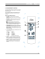
1
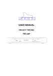
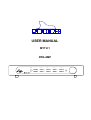
1.
USER MANUAL
MYTH 1
PRE-AMP
PHONES
CD
LINE 1
LINE 3
VIDEO
MUTE
TUNER
LINE 2
LINE 4
TAPE / MON
STANDBY
SPHINX
Myth 1
1. UNPACKING .......................................................................................................................................3
2. SPHINX WARRANTY CARD ..............................................................................................................3
3. THE PRE-AMP AT A GLANCE...........................................................................................................4
Front panel................................................................................................................................................... 4
Rear panel ................................................................................................................................................... 5
4. INSTALLATION AND CONNECTIONS ..............................................................................................6
Installation.................................................................................................................................................... 6
Connecting the mains cable ........................................................................................................................ 6
Audio connections ....................................................................................................................................... 6
Connecting the power amp .......................................................................................................................... 6
Connecting a recorder ................................................................................................................................. 6
Connecting the inputs .................................................................................................................................. 6
Connecting a tuner ...................................................................................................................................... 6
Connecting a CD player............................................................................................................................... 6
Connecting other signal sources ................................................................................................................. 6
Connecting a video source .......................................................................................................................... 6
Connecting a turntable................................................................................................................................. 6
Connecting the optical cables...................................................................................................................... 7
5. OPERATION........................................................................................................................................8
Power on...................................................................................................................................................... 8
Selecting an input ........................................................................................................................................ 8
Adjusting the volume level ........................................................................................................................... 8
Temporarily set volume to ‘zero’ .................................................................................................................. 8
Power off...................................................................................................................................................... 8
6. SPHINX REMOTE CONTROL ............................................................................................................9
Buttons and LED indication ......................................................................................................................... 9
Operation ................................................................................................................................................... 10
Selecting without switching ........................................................................................................................ 10
Batteries..................................................................................................................................................... 10
Encountering problems.............................................................................................................................. 10
7. CARE AND MAINTENANCE.............................................................................................................11
8. TECHNICAL SPECIFICATIONS .......................................................................................................11
2
SPHINX
Congratulations on your purchase of the Sphinx
Myth 1!
You are now a member of an ever-increasing group
of quality-conscious audiophiles using Sphinx
products.
We are very proud of the tradition connected with
the SPHINX name, especially concerning audio
quality perfection.
This manual will help you to gain a maximum
amount of pleasure and quality from your new
Sphinx Myth 1 Pre-Amp.
This pre-amp uses the newest technologies and
refined designs and is extremely simple to operate.
Designs that successfully have been used in the
award winning Project Eight.
Such as the ultra-linear extremely low-noise
Class-A audio circuits, built from the finest handselected parts.
The signal path is completely balanced from input
to output, and left and right are totally separated.
The power supply is of a unique design (fully ClassA!) and consists of three completely separate and
independent sections: one for the digital control,
plus one each for the left and right channel.
Input selection is done by means of precision
relays. The ALPS volume control is motor-driven.
All settings and controls can also be done via the
supplied Sphinx Remote Control.
Myth 1
1. UNPACKING
Before leaving the factory every Myth 1 is subjected
to stringent and extensive technical and exterior
quality inspection.
This ensures you will enjoy many years of high
quality audio from a perfect-looking product.
After unpacking your Myth 1, we therefore
recommend you carefully check it for any transport
damage.
In case of damage: please contact your Sphinx
dealer immediately and retain all packing materials
for possible proof of damage and possible claims.
Even if the component is in perfect condition you
should still keep the packing materials. If you need
to transport your Myth 1 at a later time it will be best
protected by the original packing materials.
2. SPHINX WARRANTY CARD
Please take this opportunity to fill out the enclosed
warranty card now!
Follow the instructions on the card or consult your
dealer.
Please send the card as soon as possible to the
return address (within 14 days after purchase).
To obtain the maximum quality from this power amp
it is necessary to use it with top quality audio
components, preferably with other Sphinx
components.
Please read this manual carefully before you
install or use the Myth 1. It is important to
familiarise yourself with the special
functions, operation and possibilities of the
Sphinx Myth 1.
Your local dealer will be able to answer any
questions concerning other Sphinx audio
components.
3
SPHINX
Myth 1
3. THE PRE-AMP AT A GLANCE
Front panel
1
PHONES
6
2
3
4
5
CD
LINE 1
LINE 3
VIDEO
MUTE
TUNER
LINE 2
LINE 4
TAPE / MON
STANDBY
7
8
9
10
11
12
13
1.
CD: To select the CD input. The red LED will
light.
8.
LINE 2: To select the Line 2 input. The red LED
will light.
2.
LINE 1: To select the Line 1 input. The red LED
will light.
9.
LINE 4: To select the Line 4 input. The red LED
will light.
3.
LINE 3: To select the Line 3 input. The red LED
will light.
10. TAPE / MON: To select the TAPE IN input. The
red LED will light.
4.
VIDEO: To select the Video line input. The red
LED will light.
5.
MUTE: Press this button to temporarily mute
the sound. The red LED will light.
11. STANDBY: To switch the component on and
off:
on
LED is off
off
LED is red
6.
PHONES: To connect dynamic stereo
headphones.
7.
TUNER: To select the Tuner input. The red
LED will light.
12. Receptor window for the IR signals from the
Remote Control.
13. VOLUME: This rotary knob adjusts the volume
level.
4
SPHINX
Myth 1
Rear panel
2
1.
TUNER: To connect the signal cable from the
tuner.
9.
2.
CD: To connect the signal cable from the CD
player.
10. Control Out: To connect the optical cable(s) to
other Sphinx component(s).
3.
TAPE OUT: Connect this output to the input of
the recorder.
11. OUT 1 and 2 L+R: Connect this output with a
signal cable to the input of your power amp.
4.
TAPE IN: Connect this input to the output of the
recorder.
5.
LINE 4: To connect the signal cable from the
signal source for LINE 4.
12. Manufacturer’s label: This shows important
data for the component, such as serial number
and mains power voltage.
6.
3
4
5
6
7
8
9
1
10
LINE 3: To connect the signal cable from the
signal source for LINE 3.
7.
LINE 2: To connect the signal cable from the
signal source for LINE 2.
8.
LINE 1: To connect the signal cable from the
signal source for LINE 1.
11
12
13
14
VIDEO: To connect the signal cable from the
audio output of the video source.
13. Warning!: This shows important information
about the safety regulations for the Myth 1.
14. AC Power: Connect the mains cable to a mains
power outlet (100 - 240 VAC).
The mains fuse is placed behind the cover.
5
SPHINX
Myth 1
4. INSTALLATION AND CONNECTIONS
Installation
Connecting the power amp
The Myth 1 will not become very hot, so placement
is not critical, although you should not place it on
top of or near other heat-radiating equipment (such
as power amps) or in direct sunlight.
If you need to use the pre-amp in a closed cabinet
or on a bookshelf, you should definitely provide
unrestricted ventilation around the component.
There are two outputs: OUT 1 and OUT 2.
Both can be used simultaneously.
To prevent any possible interference keep power
supply cables away from all audio cables.
If all these conditions are met, the Myth 1 will
perform to the extremely high standards it is
designed for.
Connecting the mains cable
Before you connect the cable please check
whether the mains voltage indicated on the
manufacturer’s label on the rear panel is the
same as your local mains voltage.
If not: please contact your dealer and do not
connect the component to the mains.
You switch the pre-amp on or off with the
m STANDBY button. This way the electronic circuits
will be kept at optimum working temperature so you
can enjoy maximum audio quality immediately after
switching on. Additionally it significantly increases
the life span of the component.
Connect the mains cable after you have connected
all other components in the system and have
double-checked all connections (see Chapter 5.)
Use a normal cinch cable (but of top quality!) to
connect OUT 1 to the corresponding inputs of the
power amp.
Use a normal cinch cable to connect OUT 2 to the
corresponding inputs of another component, such
as an extra power amp or surround processor.
Connecting a recorder
Connect the recorder's inputs to the TAPE OUT
outputs.
Connect the recorder's outputs to TAPE IN.
Connecting the inputs
The seven unbalanced inputs may be used for any
unbalanced line-level signal.
Connecting a tuner
Connect the output of a tuner to TUNER.
Connecting a CD player
Connect the unbalanced output of a CD player to
CD.
You may connect more than one CD player: the
other(s) may be connected to one of the LINE
inputs.
Connecting other signal sources
LINE 1 to LINE 4 are available for other signal
sources.
Audio connections
Before you start connecting equipment it is always
wise to check whether all the mains power cables of
all components are disconnected from the mains
outlets!
This will prevent any damage to the loudspeakers
and amplifiers caused by incorrect wiring or
settings.
Make sure you connect L and R properly. Most
cinch cables use Red for the Right channel and
White or Black for Left.
All cinch connectors on the Myth 1's rear panel
have a red centre for the right channel and a white
one for the left channel.
Connecting a video source
Connect the audio output of video source to the
VIDEO input.
Connecting a turntable
There is no specific RIAA phono-input. When using
a turntable you should pre-amplify the signal with a
separate phono pre-amp (or pre-pre-amp).
Connect the output of a phono pre-amp to one of
the inputs LINE 1 to LINE 4.
You may connect different pre-amps
simultaneously.
When making the connections please refer to the
descriptions for parts 14. to 25. on page 5.
6
SPHINX
Myth 1
Connecting the optical cables
The Myth 1 has two CONTROL OUT optical
connectors so it can remotely switch other Sphinx
components to stand-by.
When the CONTROL IN of a component is
connected to the CONTROL OUT of the Myth 1 with
an optical cable, you do not have to use that
component's ON/OFF switch. As soon as the Myth
1 is selected to stand-by the other component is
also selected to stand-by.
CONTROL OUT: These outputs are activated as
soon as the Myth 1 is switched on.
Ensure proper connection of the optical cables
(from CONTROL OUT to CONTROL IN), otherwise
the LED next to the m STANDBY button (11) on the
front panel will not light although the stand-by mode
is activated.
7
SPHINX
Myth 1
5. OPERATION
Selecting an input
Connect the mains cable to a mains outlet.
Once you have finished connecting all components,
you can power on the Myth 1 with the mains switch
O / I (29) .
You may select an input with one of the m buttons
2. to 9.: the LED will illuminate.
The new input becomes active after you have
selected it. You will hear a 'click'. This is caused by
the precision relays for the inputs: the 'old' one is
released while the new one is energised.
The volume control will then automatically turn
counter-clockwise and for a while the STANDBY
LED will blink red, after which it will remain red. The
pre-amp is now in standby mode.
Adjusting the volume level
From now on you should switch the amp on or off
with the m STANDBY button (11).
That way, all circuits will remain at optimum
operating temperatures and the audio quality will be
100% immediately after switching on. Additionally it
significantly increases the life span of the
component.
The Myth 1 is now in stand-by mode.
Power on
The large VOLUME control to the right adjusts the
volume level from OFF to maximum (fully
clockwise). The level change is immediate.
Temporarily set volume to ‘zero’
Press the m MUTE button (10) temporarily mutes
the sound. The red LED will light. Another press on
this button un-mutes the output.
Power off
You switch the Myth 1 off (to stand-by) with the
m STANDBY button (11).
Switch the Myth 1 on with the m STANDBY button.
The pre-amp will select the CD input after which it
un-mutes the output.
8
SPHINX
Myth 1
6. SPHINX REMOTE CONTROL
This single Sphinx Remote Control lets you control
all functions: not only of the Myth 1, but of all other
Sphinx equipment.
Only the following buttons and indications on the
Remote apply to the Myth 1 (the others will not
function):
Buttons and LED indication
1. PRE-AMP: To select the amp. All buttons
pressed hereafter will control only the pre-amp
functions.
The buttons TUNER and CD will have no effect.
2. STANDBY: Use this red button to switch the
Myth 1 to stand-by.
3.
: Pressing this green button mutes the
outputs (temporarily) and you will not hear any
sound. The red LED will be illuminated. Another
press on this button un-mutes the outputs
4. TAPE/MONITOR: Use this button to select the
Tape IN input. Pressing this button has the same
effect as pressing the TAPE/MON button (9) on
the front panel.
Note: The LED of the selected input (see 5.) will
remain illuminated.
5. 1 - 7: To select inputs CD to VIDEO (Note: 8 to 0
do not function):
1 CD
CD input
2 TUNER
Tuner
3 LINE 1
Line input 1
4 LINE 2
Line input 2
5 LINE 3
Line input 3
6 LINE 4
Line input 3
7 Video
Audio from video source
6. Volume ñ: Pressing this button has the same
effect as rotating the VOLUME control on the
front panel clockwise. You increase the volume.
7. Volume ò: Pressing this button has the same
effect as rotating the VOLUME control on the
front panel anti-clockwise. You decrease the
volume.
9
SPHINX
Operation
The Sphinx Remote is used with several different
models and can therefore transmit different control
codes, depending on which model has been
selected with the select buttons (1).
Important: Always press the m PRE-AMP button
before you send a command (even if you only have
one Sphinx component).
Otherwise it is possible that, although the Remote
sends a signal, nothing happens because the
transmitted signal is not 'recognised' by the
component.
Indoors the Remote may be used up to a distance of
7 meter, provided there is no strong sunlight in the
room and if you aim the Remote at the component.
Always aim the Remote straight at the front panel of
the component, the maximum offset angle is 30°.
Myth 1
Encountering problems...
Remote Control does not work
Wrong component selected
Select the correct one
Distance to component
exceeds 7 m
Use Remote at closer
range
Angle between Remote and
component exceeds ±30°
Decrease angle
Sensor window on front dirty
Clean window
Batteries empty or incorrectly
placed
Use new batteries or
replace the old ones
correctly
Strong (sun)light in room
Shade off light source
Component is not switched on
(!)
Switch it on
Selecting without switching
Suppose, for instance, that you would like to select
the Tuner to Radio 4 without interrupting CD
playback.
In that case you momentarily depress (not longer
than 0.5 sec) the m TUNER button and the m '4'
button. The same procedure is used for the other
system components.
Component reacts differently than expected or
not at all
How to operate the Remote Control with the different
Sphinx components will be explained in the
corresponding User Manual of each component.
Wrong component selected
Select the correct one
Component or Remote does
not function
Check component with
its original remote
Batteries
Batteries in Remote empty
Use new batteries
The four batteries have a life span of approximately
one year during normal use, but shorter when used
more intensely.
Replacement batteries: 1.5 V, model micro or penlite
or LR03 or AAA or AM4 (one of these codes is
indicated on the packaging and the batteries). You
may also use rechargeable 1.5 V batteries.
Note: Position the new batteries exactly as shown in
the illustration at the bottom of the battery
compartment, otherwise the Remote will not
function!
10
SPHINX
Myth 1
7. CARE AND MAINTENANCE
Clean the exterior with a soft, lint-free, anti-static
cloth. Do not use force while wiping the surface.
To remove difficult stains use a few drops of
detergent on a moist cloth, sweep carefully and
wipe dry afterwards.
Do not use polishing or cleaning agents: they
may damage the sensitive acrylic finish.
Do not use aerosol cleaning agents.
Most contain solvents which might actively react
with and damage the acrylic finish.
If some scratching occurs, please consult your
Sphinx dealer first. He can give you advice about
possible solutions.
8. TECHNICAL SPECIFICATIONS
Bandwidth
Phase response error
Gain
THD+N (IHF-A)
IMD
S/N ratio (IHF-A)
Channel separation
0 - 111,000 Hz (+0/-3 dB)
<2° ( from 0 - 20,000 Hz )
9.5 dB max. 3 times.
<0.020% / 0.002% (IHF-A) (2nd harm., 10 - 20,000 Hz)
<0.003%
>84dB / 100 dB (IHF-A)
>98 dB
Inputs
Level, nominal (for 1 V output)
impedance
8x cinch (gold-plated)
0.13 V (-18 dBV)
74 kΩ
Outputs
level
impedance
2x cinch Out 1, Out 2 (gold-plated)
1x cinch Tape (gold-plated)
10.5 V max. (20.42 dBV) (1 - 100,000 Hz, THD <0.002%)
<10 Ω
Volume control
channel imbalance
ALPS motorised
less than 2 dB
Sphinx Control
2x optical out
Remote control
Full function
Power supply
Supply capacitance
Power consumption
Dimensions (h x w x d)
Weight
External, completely stabilized
16,280 µF total
11 W (9 W stand-by)
75 x 434 x 350 mm
7 kg
This unit conforms to the EMC interference regulations issued by the EU and to the CE standards.
This unit complies with safety regulation VDE 0860 and therefore with international safety regulation IEC 65.
Technical specifications may be changed by SPHINX without prior notice if technical developments make this
necessary.
©1999 Audioscript BV
11