1
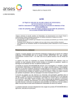
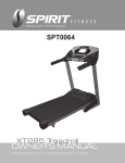
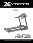
-ESP0033-
Esprit X5 Cross Trainer
OWNER’S MANUAL
PLEASE CAREFULLY READ THIS ENTIRE MANUAL BEFORE
OPERATING YOUR ELLIPTICAL!
Safety Hints
WARNING - Read all instructions before using this appliance.
■
■
■
■
■
■
■
■
■
Do not operate elliptical on deeply padded, plush or shag carpet. Damage
to both carpet and elliptical may result.
Keep children away from the elliptical. There are obvious pinch points and
other caution areas that can cause harm.
Keep hands away from all moving parts.
Never operate the elliptical if the elliptical is not working properly; call your
dealer.
Never drop or insert any object into any openings.
Do not use outdoors.
Do not attempt to use your elliptical for any purpose other than for the
purpose it is intended.
The pulse sensors are not medical devices. Various factors, including the
user’s movement, may affect the accuracy of heart rate readings. The pulse
sensors are intended only as exercise aids in determining heart rate trends
in general.
Wear proper shoes. High heels, dress shoes, sandals or bare feet are not
suitable for use on your elliptical. Quality athletic shoes are recommended
to avoid leg fatigue.
SAVE THESE INSTRUCTIONS - THINK SAFETY!
CAUTION!! Please be careful when un-packing the carton.
ESP0033/ X5_ver. A
1
Assembly Pack Check List
STEP 1.
#43- 5/16" × 3/4" Button
Head Socket Bolt (13pcs)
#44- 5/16” Flat
Washer (8pcs)
#53- M5 × 12 mm Phillips
Head Screw (4pcs)
#45- 5/16" Curved
Washer (1pc)
#89- M5 × 65m/m Phillips
Head Screw (1pcs)
#46- 5/16" Split
Washer (9pcs)
STEP 2.
#43- 5/16" × 3/4" Button
Head Socket Bolt (1pc)
STEP 3.
#43- 5/16" × 3/4" Button
Head Socket Bolt (1pc)
#55- 5/16"
Nyloc Nut (2pcs)
#92- 8.5x23x1.5T
Flat Washer (1pc)
#56- 5/16" ×1-3/4" Button
Head Socket Bolt (2pcs)
#55- 5/16"
Nyloc Nut (2pcs)
#56- 5/16" ×1-3/4" Button
Head Socket Bolt (2pcs)
2
#92- 8.5x23x1.5T
Flat Washer (1pc)
Assembly Pack Check List
STEP 4.
#91- 5/16" × 1" Button
Head Socket Bolt (2pcs)
#44- 5/16” Flat
Washer (2pcs)
#29- 1/2" × 70mm
Carriage Bolt (2pcs)
#68- 19m/m Wrench (1pc)
#67- Combination M5 Allen Wrench &
Phillips Head Screw Driver (2pcs)
3
#46- 5/16" Split
Washer (2pcs)
#30- 1/2" Nyloc
Nut (2pcs)
Assembly Instructions
STEP 1:
1.
2.
3.
4.
5.
6.
Install the Steel Cable Assembly (59) on the Console Mast (2) using 1pcs of M5 ×
65m/m Phillips Head Screw (89) to tighten.
Locate the Console Mast (9) and slide on Console Mast Cover (79). Make sure the
cover is facing the correct direction, as shown below, before sliding onto mast. Install
the wiring harness (90) into the bottom of the mast and out the top. Be careful when
installing the console mast to the mainframe so as not to pinch or cut the wiring
harness; damage to the console may occur.
Install the console mast on the mainframe using the M5 Allen Wrench (67) to tighten
5pcs of 5/16” Button Head Socket Bolts (43), 4pcs of 5/16” Flat Washers (44), 5pcs of
5/16" Split Washers (46) and 1pc of 5/16" Curved Washer (45). Snap the Console
Mast Cover (79) in place on the body of the elliptical.
Route the hand pulse wires (90) from the stationary handle bars (10, 11) through
Console Mast (9) as shown below. Use M5 Allen Wrench (67) to tighten 4pcs of 5/16”
Button Head Socket Bolts (43) to secure both handles on the Console Mast (9).
Connect the cables (62, 90) to the Console (58) and install console onto the Mast (9)
with 4pcs of M5 × 12L Phillips head screws (53) by using the Phillips Head Screw
Driver (67).
Secure Front Stabilizer (12) and Rear Stabilizer (13) with 4pcs of 5/16” Button Head
Socket Bolts (43), 4pcs of 5/16" Split Washers (46) and 4pcs of 5/16” Flat Washers (44)
by using M5 Allen Wrench (67).
4
5
STEP 2:
1.
Locate the Right Swing Arm (Upper) (8) and install it through the Swing Arm Bushing
(23) and secure to the Lower swing arm (6). Use M5 Allen Wrench (67) to tighten 2pcs
of 5/16” Button Head Socket Bolts (56) and 2pcs of 5/16" Nyloc Nuts (55) to the swing
arm assembly.
2.
Locate the Swing Arm Axle (22) and slide it through the console mast bushings then
through the Lower swing arm (6). Use the M5 Allen Wrench (68) to tighten the 5/16”
Button Head Socket Bolt (43) and 8.5mm x 23 Flat Washer (92) to secure to the Swing
Arm Axle (22).
6
STEP 3:
1.
Locate the Left Swing Arm (Upper) (7) and install it through the Swing Arm Bushing (23)
and secure to the Lower swing arm (5). Use M5 Allen Wrench (67) to tighten 2pcs of
5/16” Button Head Socket Bolts (56) and 2pcs of 5/16" Nyloc Nuts (55) to the swing
arm assembly.
2.
Slide the swing arm onto the axle (22). Secure the swing arm to the axle using the M5
Allen Wrench (67) to tighten the 5/16” Button Head Socket Bolt (43) and 8.5mm x 23
Flat Washer (92) on the Swing Arm Axle (22).
Check if there is a gap at location A as shown in the inset picture below. If there is a
gap then insert one of the provided C washers in the gap to prevent noise issues.
3.
7
STEP 4:
1. Locate Right side Pedal Arm Assembly (2) and install onto the pedal axle at the
large rotating wheel at the rear of the elliptical. Use the M5 Allen Wrench (67) to
tighten the 5/16” Button Head Socket Bolt (91), 5/16" Split Washer (46) and 5/16”
Flat Washer (44).
2. Locate the 1/2" × 2-3/4” Carriage Bolt (29) and slide through the bracket at the front
of the Pedal Arm Assembly (2) and Lower swing arm (6). Use the19m/m Wrench (68)
to tighten the 1/2" Nyloc Nut (30) to the carriage bolt (29).
3. Repeat steps 1&2 above for the left side pedal arm assembly.
8
Console
FUNCTION BUTTONS
MODE
SET
RESET
1. Press Mode button to select hour, minute, year, month and date when
batteries are installed.
2. Press the mode button to select TIME, DISTANCE, CALORIES or
PULSE to preset a goal value.
3. Press the mode button during exercise to select which data will be
displayed in large LCD window.
4. Press the button to confirm setting value of gender, age, height and
weight in the Body fat mode.
5. Press the button and hold for 2 seconds to reset all value to zero and
return to idle mode. (When the user replace batteries, all the values will
reset to ZERO automatically.)
1. Press to set the hour, minute, year, month and date after choosing
each one using the Mode key (this function operates only when batteries
are first installed or replaced)
2. To set the target value of Time, Distance, Calories and Pulse in idle
mode. You can hold the button to increase the value fast.
3. To set up the personal data of gender, age, height and weight for
Body fat test.
1. Press the Reset button to reset values while inputting data.
2. Press the button and hold for 2 seconds to reset all values to zero.
9
BODY FAT
RECOVERY
Press this button to enter Body Fat measure function then press MODE
key to enter setup of your personal data of Gender, Age, Height and
Weight. After completing data entry press it again to measure your Body
fat ratio (FAT%) and BMI.
Press to enter the heart rate recovery function.
LCD display
LCD FUNCTIONS
SCAN
TIME
RPM
SPEED
DISTANCE
CALORIES
PULSE
CALENDAR
CLOCK
Press the Mode button until Scan icon lights. Automatically scans through
each data in sequence every 6 seconds. The display loop is RPM –
Speed – Time – Distance – Calorie - Pulse on the main screen.
Accumulates time from 0:00 up to 99:59. The user may preset target time
by pressing MODE then SET button. Each increment is 1 minute.
Displays the Revolutions per Minute (RPM). The RPM and SPEED
numbers will alternate every 6 seconds during exercise.
Displays current training speed. Maximum speed is 99.9 km/h or mile/h.
Accumulates total distance from 0.00 up to 99.99 km or mile. The user
may preset a target distance goal by pressing MODE then SET button.
Each press of the button increments the setting 0.5 km or mile.
Accumulates calorie consumption during training up to a maximum of 999
calories. The user may also preset a target calorie goal before training by
pressing MODE then SET button. Each press of the button increments
the setting 10 cal.
Note : This data is a rough guide for comparison of different
exercise sessions and can not be used for medical purposes.
The monitor will display the user's heart rate in beats per minute during
training. You may set a target heart rate goal by press the MODE then
SET button.
The monitor will display date, month, and year when the monitor is in
sleep mode.
The monitor will display current clock time when the monitor is in sleep
mode.
10
TEMPERATURE Displays current room temperature from 10
monitor is in sleep mode.
℃ to 60℃ when the
MONITOR OPERATION:
1.
Power on:
Install two 1.5V UM-3 or AA batteries. The monitor will perform an LCD segment test
indicated by a long beep sound. (Whenever batteries are removed, all the data values
will be reset to zero or default value.)
2.
Setting the clock:
Press the MODE and SET buttons to set the clock time, year, month, and day.
After the initial setting the time and calendar will be updated automatically until the
batteries are changed again.
3.
Select and preset target goal values:
Access the setting function for Time, Distance, Calories and Target Pulse by pressing
the Mode button. Press the SET button to adjust the value of each function. Press the
MODE button for confirmation and skip to next setting. The setting for Distance &
Calories operates the same as Time setting.
4.
After a speed signal is detected each data reading SPEED, RPM, TIME, DISTANCE,
CALORIES and PULSE will begin.
5.
You can press the MODE button to select single reading to be displayed in the main
screen.
6.
If you have preset any target, the value will begin to count down from the target setting
when the training starts. Once the target is achieved, the monitor will beep and the
function will count up from zero automatically if training continues.
7.
Pulse measurement –
Hold the two handgrip sensors for a few seconds and the monitor will display your
current heart rate in beats per minute. To ensure proper heart rate readings
please place both hands on the sensors and try not to change grip strength; hold in a
relaxed manner. You may preset a heart rate limit alarm before training starts. Once
your heart rate reaches the limit value the console will beep to let you know you are at
the limit. This is used to make sure you do not exceed your desired heart rate.
8.
Recovery –
Press the “RECOVERY” button to start the recovery test function. The monitor will
count down from 0:60 second to 0:00. The heart Icon will blink during count-down to
“0:00”, during the count-down period please keep your hands on the heart rate sensors.
When the time reaches zero the screen will display “F1 to F6” indicating your recovery
status. F1 is the highest, and the F6 the lowest score. You may keep exercising to
improve your heart rate recovery status, and check it by using the Recovery function.
11
9.
Body Fat 9-1. Press BODY FAT key to enter body fat measurement.
9-2. Press MODE and SET buttons to input your personal data. Each personal data
setting is described as the following:
AGE:
10 ~ 99 years
HEIGHT:
100 ~ 250 cm (or 3’03” ~ 8’02“)
WEIGHT:
10 ~ 200 kg (or 22 ~ 440 lb)
9-3. After all personal data have been input, you can press BODY FAT button and hold
the grip sensors to start the body fat testing.
9-4. It takes few seconds to measure the body fat. If you do not hold the sensors during
the testing procedure the LCD will show an error ‘Err’ after a 10 second period.
9-5. After the measurement is finished the display will show your Body Fat reading in
percentage, and BMI calculation (body mass Index) in the main LCD window. The
measurements will alternate in scan mode.
BODY FAT % : Calculated from your personal data and is shown as a value from
5%~50%.
BMI : Calculated from your personal data and is shown as a value from 1.0~99.99.
9-6.Press any key to return to the main display.
Note
1. If you Stop training for 4 minutes, the screen will show room temperature, clock, and
calendar display automatically.
2. If the computer is operating abnormally, please re-install the batteries and try again.
3. Battery Spec: 1.5V UM-3 or AA (2PCS).
4. The batteries must be removed from the appliance before it is scrapped. Please
dispose of batteries properly.
Note :
1.
Do not dispose of electrical appliances as unsorted municipal waste,
use separate collection facilities.
2.
Contact your local government for information regarding the collection
systems available.
3.
If electrical appliances are disposed of in landfills or dumps, hazardous substances
can leak into the groundwater and get into the food chain, damaging your health and
well-being.
12
Parts List
NO.
DESCRIPTION
O'TY
1
2
3
Main Frame
Pedal Bar Assembly (R)
Pedal Bar Assembly (L)
1
1
1
4
5
6
Cross Bar
Lower Handle Bar (L)
Lower Handle Bar (R)
2
1
1
7
8
9
Left Swing Arm (Upper)
Right Swing Arm (Upper)
Console Mast
1
1
1
10
11
12
Hand Pulse Sensor Arm (L)
Hand Pulse Sensor Arm (R)
Front Stabilizer
1
1
1
13
14
15
Rear Stabilizer
Crank Axle
Pedal Axle Bushing Assembly
1
1
2
16
17
19
Flywheel
Flywheel Magnets Mounting Plate
Drive Pulley
1
1
1
20
21
22
Idler Bracket
Idler Wheel
Swing Arm Axle
1
1
1
23
24
25
Swing Arm Bushing
Ø38.1 × 34.1 × 16 × 21L_Bushing
Pedal Axle Spacer
2
4
2
26
27
28
15.9 × 22.2m/m_Podwer metallurgy Bushing
12.7 × 18m/m_Podwer metallurgy Bushing
6004_Flywheel Bearing
6
4
2
29
30
31
1/2" × 70L_Carriage Bolt
1/2" × 8T_Nyloc Nut
Belt
2
2
1
32
33
35
M8 × 170L_J Bolt
M8 × 7T_Nyloc Nut
3/8" × 27L_Carriage Bolt
1
1
1
36
3/8" × 7T_Nyloc Nut
1
13
NO.
DESCRIPTION
O'TY
37
38
39
Sleeve
5/16" × 20L_Carriage Bolt
20m/m_C Ring
1
1
2
40
41
42
M10 × 1.25_Nut
3/8"-26UNF × 4T_Nut
3/8"-26UNF × 11T_Nut
2
2
2
43
44
45
5/16" × 3/4"_Button Head Socket Bolt
5/16" × 18 × 1.5T_Flat Washer
5/16" × 19 × 1.5T_Curved Washer
15
13
1
46
47
48
5/16" × 1.5T_Split Washer
1/4" × 5/8"_Hex Head Bolt
1/4" × 5.5L_Nyloc Nut
11
4
4
49
50
51
1/4" × 13 × 1T_Flat Washer
1/4"_Split Washer
5 × 16L_Tapping Screw
4
4
6
52
53
54
4 × 12L_Sheet Metal Screw
M5 × 12L_Phillips Head Screw
M5 × 30L_Phillips Head Screw
17
5
8
55
56
57
5/16" × 6T_Nyloc Nut
5/16" × 1-3/4"_Button Head Socket Bolt
5/16" × 2-1/2"_Button Head Socket Bolt
8
4
3
58
59
60
Console
Steel Cable Assembly
Magnet
1
1
1
61
62
63
Handpulse Sensor (w/o wire)
2400m/m_Sensor W/Cable
Ø31.8 × 3T × 400L_Handgrip Foam
2
1
2
64
65
66
Ø32-3T_Button Head Plug
Ø25.4 × 3T × 150L_Handgrip Foam
Ø25.4-3T_Button Head Plug
2
2
2
67
68
69
Combination M5 Allen Wrench & Phillips Head Screw Driver
19m/m_Wrench
Left Stabilizer End Cap (Front)
2
1
1
70
71
72
Right Stabilizer End Cap (Rear)
Left Stabilizer End Cap (Front)
Right Stabilizer End Cap (Rear)
1
1
1
73
Front Shroud (R)
1
14
NO.
DESCRIPTION
O'TY
74
75
76
Front Shroud (L)
Rear Shroud (R)
Rear Shroud (L)
1
1
1
77
78
79
Round Disk
Round Disk Cover
Console Mast Cover
2
2
1
80
81
82
Pedal (L)
Pedal (R)
Power Bracket
1
1
1
83
84
85
Console Mast Cover
M5-75L_Phillips Head Screw
M5-5T_Nyloc Nut
1
1
1
86
87
88
5.5 × 15 × 1.5T_Flat Washer
3.5 × 20L_Sheet Metal Screw
5 × 16L_Tapping Screw
8
2
8
89
90
91
M5 × 65L_Phillips Head Screw
600m/m_Hand Pulse Sensor Assembly W/Cable
5/16" × 1"_Button Head Socket Bolt
1
2
2
92
8.5 × 23 × 1.5T_Flat Washer
2
15
16
WARRANTY, SAFETY AND ASSEMBLY INFORMATION
ESP0033 – X5
IMPORTANT
Please read and retain this manual as it will assist with identification for parts and service.
-----------------------------------------------------------------------------------------------------------BOYLES FITNESS warrants their Cross Trainer to be free from defects in material and
workmanship under normal use and service conditions.
The various components of the Cross Trainer are warranted against defects and
workmanship for the time periods specified as follows:
ESP0033 – X5
Domestic use
Lifetime frame & 1 year on all other parts.
All warranty coverage extends only to the original retail purchaser from the date of
purchase. BOYLES FITNESS’ obligation under this Warranty is limited to replacing or
repairing, at BOYLES’ option, the product or parts therein. Any enquiries relating to
warranties or spare parts must be directed to 07 3272 7010
For efficient processing of your enquiry please have relevant date of purchase, retailer
name you purchased the item from and the brand on the product. This warranty does not
extend to any damage to a product caused by abuse, improper or abnormal usage (as
detailed in this instruction manual), or repairs not provided by BOYLES. Nor does this
warranty extend to products used for commercial or rental purposes. This warranty does
not cover ordinary wear, tear and weathering, failure to follow directions, improper
installation, improper maintenance or acts of God (such as damage caused by storms,
lightning and by snow or ice). No other Warranty beyond that specifically set forth above is
authorised by BOYLES.
Our sales and service centre has been set up to provide assembly assistance, replacement
parts and accessories, and to efficiently handle all warranty related matters.
Freecall
Hours
Website
07 3272 7010
9:00am – 4:30pm Mon-Fri (excluding public holidays),
9:00am – 3:00pm Sat
www.bfe.net.au
17
WARRANTY INFORMATION
ESP0033
Congratulations on your purchase!
st
As of January 1 2012, new legislation under the Australian Consumer Law requires
certain information to be included in any product warranty issued in Australia. This
warranty compliments the warranty found in the manual and has been developed in
line with the Australian Consumer Law. If the warranty periods offered in the two
documents are different then the greater of the two shall be honoured.
This Esprit X5 Cross Trainer is warranted to be free from defects in material and
workmanship under normal use and service conditions for a period of 6 months from
the date of purchase of this article. Evidence of unfair usage or incorrect adjustment by
the owner will void this promise.
The benefits conferred by this manufacturer's warranty are in addition to all rights and
remedies conveyed by the Competition and Consumer Act 2010 (Commonwealth),
and any other statutory rights to which you may already be entitled, and this warranty
does not exclude, restrict or modify any such rights or remedies that are implied by
law.
Our goods come with guarantees that cannot be excluded under the Australian
Consumer Law. You are entitled to a replacement or refund for a major failure and for
compensation for any other reasonably foreseeable loss or damage. You are also
entitled to have the goods repaired or replaced if the goods fail to be of acceptable
quality and the failure does not amount to a major failure.
Conditions of Warranty
All warranty coverage extends only to the original retail purchaser from the date of
purchase. Please keep your receipt, tax invoice or other proof of purchase.
This warranty does not extend to any damage to a product caused by abuse, improper
or abnormal usage, or repairs not provided by us or our Service Centre. Nor does this
warranty extend to products used for commercial or rental purposes. This warranty
does not cover ordinary wear, tear and weathering, failure to follow directions,
improper installation, improper maintenance or acts of God (such as damage caused
by storms, lightning, heavy winds and by snow or ice).
Making A Warranty Claim
In order to make a claim under this warranty please direct your enquiries to our
Service Centre. You can contact them on 07 3272 7010 or email
[email protected]
18
A service representative will then assist you in the appropriate action to be taken. For
efficient processing of your enquiry please have proof of purchase, the date of
purchase and the retailer name you purchased the item from, and the brand on the
product. Photos of the product, and scans of receipts, may be requested to assist with
your claim.
The service centre representative will assess the claim. If:
1) there is a minor fault, they can offer either a replacement spare part,
replacement unit, repair or other suitable remedy;
2) there is a major fault, they can offer a replacement, repair or suggest you
return to the store you purchased it from for a full refund.
Please note – a request for compensation will need documentary evidence of
the loss or damage suffered. It will also need to be evidenced that such a loss
was a reasonably foreseeable result of a failure by Boyles Fitness to comply
with a consumer guarantee under the Australian Consumer Law.
3) The product was damaged through abnormal use, no refund or repair can
be offered.
The sending of replacements, spare parts or the cost of repair carried out by the
Service Centre will be organized and covered by Boyles Fitness. If collection of the
item is required this will be organized by the Service Centre and at our expense. Do
not return any products without authorization as this will be at your expense.
Our sales and service centre has been set up to provide assembly assistance,
replacement parts and accessories, and to efficiently handle all warranty related
matters. Please note upon receiving your warranty claim our Service Centre will send,
via post or email, a repair and refurbished goods or parts notice.
SERVICE CENTRE
Contact details and hours of operation.
Freecall
07 3272 7010
9:00am – 4:30pm Monday to Friday (excluding Public Holidays)
9:00am – 3:00pm Saturday
This product is warranted by Boyles Fitness Equipment Pty Ltd 130 Carrolls Road,
Menangle NSW 2568 Phone 02 4636 6680
19