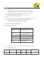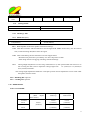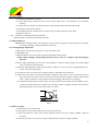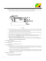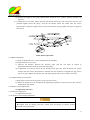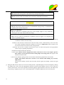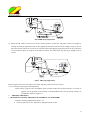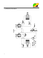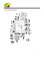
1
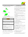
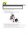
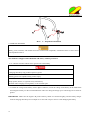
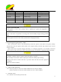
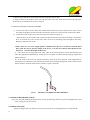
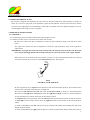
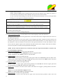
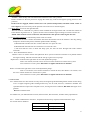
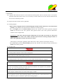
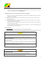
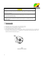
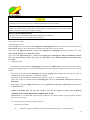
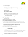
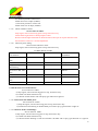
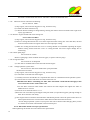
Operator’s Manual
R
WYZ 52/60
Zero Turn Mower
Worldlawn Power Equipment, Inc.
422 Turnbull Canyon Road, City of Industry, CA 91744
Toll Free Number:1-866-9-Mowers(1-866-966-9377)
OPERATOR’S MANUAL
This manual contains assembly, operating, maintenance, adjustment and safety instructions for your
WYZ52/ WYZ60 lawn mower.
Before operating your mower, carefully read this manual in its entirety.
By following the operating, maintenance, adjustment and safety instructions, you will prolong the life of your
mower, maintain its maximum efficiency and promote safe operation.
Keep this mower Owner’s Manual when lent or transferred.
Should this mower Operator’s Manual become lost, damaged or illegible, replace immediately, replacements
may be ordered through our sales department. If additional information is needed, contact our sales
department or a dealer. Always give the model number and serial number.
To improve the quality, maneuverability and security of our products, we may make changes of our products.
Sorry for the inconvenience if you find the products in hand a bit different from the manual.
POTENTIAL HAZARD
· This product is a piece of power equipment
WHAT CAN HAPPEN
· Failure to follow safe operating practices can result in serious operator injury or even death
HOW TO AVIOD THE HAZARD
· Keep all shields, guards and safety devices (especially the grass discharge system)in place and in
proper working condition.
· Stop machine and wait for all moving parts to stop ,remove spark plug wires or remove key
before adjusting ,servicing, or performing maintenance.,
· If mower deck becomes clogged, stop machine and wait for all moving parts to stop. Remove
spark plug wire or remove key before cleaning blockage .
· Keep hands ,feet ,and clothing away from power driven parts ,
· Keep others off mower.
POTENTIAL HAZARD
· Gasoline is harmful or fatal if swallowed.Long-term exposure to vapors have been known to
caused cancer in laboratory animals .
WHAT CAN HAPPEN
· Failure to use caution may cause serious injury or illness,
HOW TO AVIOD THE HAZARD
· Avoid prolonged breathing of vapors .
· Keep face away from nozzle and gas tank opening
· Keep away from eyes and skin.
· Never siphon by mouth .
TABLE OF CONTENTS
1. SAFETY……………………………………………………………………………………
1.1
1
Safety Alert Symbol…………………………………………………………………
1
1.2 Training…………………………………………………………………………….
1
1.3
Preparation………………………………………………………………………….
1
1.4
Operation…………………………………………………………………………...
2
1.5
Maintenance & Storage……………………………………………………………...
5
1.6 Safety Signs………………………………………………………………………...
6
2. SPECIFICATIONS…………………………………………………………………………
9
2.1
Model Number……………………………………………………………………
9
2.2 Engine…………………………………………………………………………….
9
2.3
Fuel System……………………………………………………………………….
9
2.4
Electrical System………………………………………………………………….
9
2.5.
Operator Controls………………………………………………………………..
9
2.6.
Seat……………………………………………………………………………….
10
2.7
Hydrostatic Ground Drive System………………………………………………..
10
2.8.
Tires And Wheels………………………………………………………………...
10
2.9. Cutting Deck………………………………………………………………………
11
2.10. Dimension………………………………………………………………………...
11
2.11. Torque Requirements……………………………………………………………..
12
3. ASSEMBLY INSTRUCTIONS…………………………………………………………
12
3.1
Uncrate Mower…………………………………………………………………....
12
3.2
Initial Instructions ………………………………………………………………...
12
3.3
Service Battery…………………………………………………………………….
14
3.4 CHECK TIRE PRESSURE…………………………………………………………………….
15
3.5 INSTALL SEAT………………………………………………………………………………….
15
3.6 INSTALL MOTION CONTROL LEVERS………………………………………………………
16
3.7 Position Discharge Chute……………………………………….............................................
16
3.8 Service Engine……………………………………………………………................................
16
3.9. Service Hydraulic Oil…………………………………………………………….………….
17
4. OPERATION INSTRUCTIONS………………………………………………………………………
17
4.1 Controls………………………………………………………………………………
17
4.2
Pre-Start…………………………………………………………………………….
19
4.3
Mowing…………………………………………………………….………………
20
4.4
Transporting…………………………………………….……………………….…
21
5. MAINTENANCE & ADJUSTMENTS………………………………………………………..……..
22
5.1
Periodic Maintenance………………………………………………………………
5.2 ADJUSTMENTS……………………………………………………………..………………..
22
29
6. TROUBLE SHOOTING……………………………………………………………………..
33
7. HYDRAULIC DIAGRAM…………………………………………………………….……..
36
8. ELECTRICAL DIAGRAM……………………………………………………………………………
37
WARRANTY…………………………………………………………………………………………….
38
operator or user is responsible for accidents or
hazards occurring to other people or their property.
1. SAFETY
1.1 SAFETY ALERT SYMBOL
This SAFETY ALERT SYMBOL
1.3 PREPARATION
is used
both in this manual and on the machine to identify
important safety messages which must be followed to
avoid accidents. This symbol means:
ATTENTION! BECOME ALERT!
YOUR SAFETY IS INVOLVED!
The safety alert symbol appears above
information which alerts you to unsafe actions or
situations and will be followed by the word
DANGER, WARNING, or CAUTION.
: White lettering/Red background.
Indicates an imminently hazardous situation
Which, if not avoided, WILL result in death or
serious injury.
: Black lettering/Orange background.
Indicates a potentially hazardous situation which,
if not avoided, COULD result in death or serious
injury.
: Black lettering/Yellow background.
Indicates a potentially hazardous situation which,
if not avoided, MAY result in minor or moderate
injury.
1.2 TRAINING
1.2.1 Regard the Mower as a piece of power
equipment and teach this regard to all who operate
this unit.
1.2.2 Read the instructions carefully. Familiarize
yourself with the controls and the proper use of the
equipment.
1.2.3 Do not allow operation of this machine by
untrained personnel. Never allow children,
teenagers, or anyone unfamiliar with these
instructions to use the mower.
1.2.4 Avoid mowing while people, especially
children, or pets, are nearby. Keep in mind that the
1.3.1 Evaluate the terrain to determine what
accessories and attachments are needed to properly
and safely perform the job. Only use accessories and
attachments approved by
Worldlawn Power Equipment, Inc.
1.3.2 The use of personal protective equipments,
such as (but not limited to) protection for the eyes,
ears, feet, and head is recommended.
POTENTIAL HAZARD
· This machine produces sound levels in excess of
85 dBA at the operator’s ear when in operation.
WHAT CAN HAPPEN
· Exposure to sound levels of 85dBA or above for
extended periods of time can cause hearing loss.
HOW TO AVOID THE HAZARD
· Wear hearing protection when operating this
machine.
1.3.3 While mowing, always wear substantial
footwear and long trousers. Do not operate
equipment when barefoot or when wearing open
sandals.
1.3.4 Thoroughly inspect the area where the
equipment is to be used and remove all stones, sticks,
wires, bones, and other foreign objects which may
damage the equipment or cause personal injury to
operator or bystanders.
POTENTIAL HAZARD
· Engine exhaust contains carbon monoxide, which
is an odorless deadly poison.
WHAT CAN HAPPEN
· Carbon monoxide can kill you.
HOW TO AVOID THE HAZARD
· Do not run engine indoors or in a small confined
area where dangerous carbon monoxide fumes can
collect.
1
POTENTIAL HAZARD
· In certain conditions gasoline is extremely
flammable and highly explosive.
WHAT CAN HAPPEN
· A fire or explosion from gasoline can burn you,
others, and cause property damage.
HOW TO AVOID THE HAZARD
· Do not smoke while refueling, and stay away from
an open flame or where gasoline fumes may be
ignited by spark.
· Refuel only outdoors.
· Store gasoline in an approved container and keep
it out of the reach of children.
· Add fuel before starting the engine. Never remove
the cap of the fuel tank or add fuel when engine is
running or when the engine is hot.
· Never fill the fuel tank so that gasoline level rises
above a level that is 10(mm) below the bottom of
the filler neck to allow for gasoline expansion and
prevent fuel spillage.
· If fuel is spilled, DO NOT attempt to start the
engine. Move away from the area of the spill and
avoid creating any source of ignition fuel until
vapors have dissipated.
· Do not operate without entire exhaust system in
place and in proper working condition.
POTENTIAL HAZARD
· In certain conditions gasoline is extremely
flammable and highly explosive.
WHAT CAN HAPPEN
· A static charge can ignite gasoline vapors. A fire
or explosion from gasoline can burn you, others,
and cause property damage.
HOW TO AVOID THE HAZARD
· Purchase and store gasoline only in an approved
container.
2
· Always place gasoline containers on the ground
away from your vehicle while filling.
· Do not fill gasoline containers inside a vehicle or
on a truck or trailer bed because interior carpets or
plastic truck bed liners may insulate the container
and slow the loss of any static charge.
· When practical, remove gas-powered equipment
from the truck or trailer and refuel the equipment
with its wheels on the ground.
· If this is not possible, then refuel such equipment
on a truck or trailer from a portable container,
rather than from a gasoline dispenser nozzle.
· If a gasoline dispenser nozzle must be used, keep
the nozzle in contact with rim of the fuel tank or
container opening at all times until fueling is
complete.
POTENTIAL HAZARD
· Gasoline vapor can collect inside enclosed trailers
and may be ignited by electrical sparks or hot
engine/exhaust components.
WHAT CAN HAPPEN
· Explosion and fire may occur, resulting in
property damage, personal injury, and/or death.
HOW TO AVOID THE HAZARD
· Provide adequate ventilation of any enclosed
trailer to prevent build up of gasoline vapors,
especially at floor level.
· Refuel only outdoors, never inside an enclosed
trailer.
· Be sure all fuel tanks and gasoline storage
containers have proper caps installed to prevent
spillage and minimize vapor escaping into the
trailer.
· Do not place any equipment that is leaking
gasoline in an enclosed trailer.
1.4 OPERATION
Although hazard control and accident prevention
partially are dependent upon the design and
configuration of the equipment, these factors are also
dependent upon the awareness, concern, prudence,
and proper training of the personnel involved in the
operation, transport, maintenance and the storage of
the equipment. It is essential that all Operator Safety
Mechanisms be connected and in operating condition
prior to use for mowing.
POTENTAL HAZARD
· Operating engine parts, especially the muffler,
becomes extremely hot.
WHAT CAN HAPPEN
· Severs burns can occur on contact.
· Debris, such as leaves, grass, bush, etc. can catch
fire.
HOW TO AVOID THE HAZARD
· Allow engine parts, especially the muffler, to cool
before touching.
· Remove accumulated debris from muffler and engine
area.
· Install and maintain in working order a spark arrester
before using equipment on forest-covered,
grass-covered, or brush-covered unimproved land.
NEVER carry passengers. DO not operate the mower
when children or others are in the area!
1.4.3 When feasible, avoid operating the equipment in
wet grass.
1.4.4 Use mower caution when mowing and/or turning
on slopes as loss of traction and/or tip-over could
occur. The operator is responsible for safe operation
on slopes.
POTENTIAL HAZARD
· Mowing on wet grass or steep slopes can cause
sliding and loss of control.
WHAT CAN HAPPEN
· Wheels dropping over edges, ditches, steep banks,
or water can cause rollovers, which may result in
serious injury, death or drowning.
HOW TO AVOID THE HAZARD
· Do not mow on slopes when grass is wet.
· Do not mow near drop-offs or near water.
· Do not mow on slopes greater than 15 degrees.
· Reduce speed and use extreme caution on slopes.
· Avoid sudden turns or rapid speed changes.
z
z
POTENTIALHAZARD
· Hands, feet, hair, clothing, or accessories can become
entangled in rotating parts.
z
WHAT CAN HAPPEN
· Contact with rotating parts can cause traumatic
amputation or severe lacerations.
z
HOW TO AVOID THE HAZARD
· Do not operate the machine without guards, shields,
and safety devices in place and working properly.
· Keep hands, feet, hair, jewelry, or clothing away
from rotating parts.
z
1.4.1 Give complete, undivided attention to the job at
hand.
1.4.2 Mow only in daylight or good artificial light,
keeping away from holes and hidden hazards.
z
z
See inside the back cover to determine the
approximate slope angle of the area to be mowed.
Use a walk behind mower /or a hand trimmer
near drop-offs, ditches, steep banks or water. This
area can be dangerous, see Figure1.
Progressively greater care is needed as the slope
increases.
Always avoid sudden starting or stopping on a
slope. If tires lose traction, disengage the blades
and proceed slowly off the slope.
Avoid sudden starts when mowing uphill. Mower
may tip backwards.
Be aware that loss of traction may occur going
downhill. Weight transfer to the front wheels may
cause drive wheels to slip and cause loss of
braking and steering.
Watch for ditches. Holes, rocks, dips, and rises
that change the operating angle, as rough terrain
could overturn the machine.
3
z
Use extreme care with grass catchers or
attachments. These can change the stability of the
machine and cause loss of control.
Danger
Zone
Safe
Zone
FIG 1
SAFE ZONE FOR MOWING
1.4.5 A Rollover Protection System (roll bar) is
installed on the unit.
POTENTIAL HAZARD
· There is no rollover protection when the roll bar is
down.
WHAT CAN HAPPEN
· Wheels dropping over edges, ditches, steep banks, or
water can cause rollovers, which may result in
serious injury, death or drowning.
HOW TO AVOID THE HAZARD
· Keep the roll bar in the raised and locked position
and use seat belt.
· lower the roll bar only when absolutely necessary.
· Do not wear seat belt when the roll bar is down.
· Drive slowly and carefully.
· Raise the roll bar as soon as clearance permits.
· Be certain that the seat belt can be released quickly if
the machine is driven or rolls into ponds of water.
· Check carefully for overhead clearance. (i.e.
branches, doorways, and electrical wires) before
driving under any objects and do not contact them.
1.4.6 Use caution when backing up.
4
LOOK BEHIND YOU!!
1.4.7 Stop the blades when transporting the mower
to and from the area to be mowed.
1.4.8. Never operate the mower with defective
guards, shields, or covers. Always have safety shields,
guards, switches, and other devices in place and in
proper working condition.
1.4.9. DO NOT change the engine governor setting
or overspend the engine. Operating an engine at
excessive speed may increase the hazard of personal
injury.
1.4.10 Disengage PTO before starting engine.
1.4.11 Start the engine carefully with feet well away
from the blades.
1.4.12 Keep hands, feet, and clothing away from
rotating parts while the mower is being operated.
1.4.13 Stop engine, wait for all mowing parts to stop ,
and remove key:
z Before checking, cleaning or working on the
mower.
z After striking a foreign object (inspect mower for
damage and make repairs before restarting and
operating the mower).
z Before clearing blockages.
z When ever you leave the mower.
Stop the engine and wait for all moving parts to stop:
z Before refueling.
z Before dumping the grass catcher.
1.4.14.Before stopping the engine, place the throttle
control midway between the “slow” and “fast”
positions. Allow the engine to run a minimum of 15
seconds,then stop the engine.
1.4.15 The fuel system is provided with a shut-off
valve, CLOSE VALVE:
z When the machine will not be used for a few
days.
z During transport to and from the job.
z When parked inside a building.
z TO remove the fuel tank.
1.4.16 This mower was designed for one operator only.
Keep all others away from mower during operation.
1.4.17 DO NOT mow with the discharge deflector
raised, removed, or altered unless there is a grass
collection system or mulch kit in place and working
properly.
1.4.18 Be aware of the mower discharge and direct
discharge away from others.
1.4.19. DO NOT operate the mower under the
influence of alcohol and / or drugs.
1.4.20 Use extra care when approaching blind corners,
shrubs, trees, or other objects that may obscure vision.
1.4.21 If jump starting is required:
a)
Connect the positive (+) power cable to the
positive terminal post on the starter solenoid switch
b)
Connect the negative (-) power cable to
any engine deck ground, preferably the
engine block as far away from the
battery as possible.
c) Disconnect battery cables in the reverse
order after starting.
1.5 MAINTENANCE AND STORAGE
1.5.1 For engine maintenance, follow the engine
manufacture’s recommendations precisely as stated in
the engine manual.
1.5.2 Disconnect the battery cable form the negative
battery post when the unit will be allowed to sit for
more than 30 days without use.
1.5.3 Allowing batteries to stand for an extended
period of time without recharging them will result in
reduced performance and service lift. To preserve
optimum battery performance and lift, recharge
batteries in storage when the open circuit voltage
drops to 12.4 volts.
1.5.4 Keep engine, engine area, free from
accumulation of grass, leaves, excessive grease, or oil
and other debris, which can accumulate in this areas.
These materials can become combustible and may
result in a fire.
1.5.5. Store fuel in a container specifically designed
for this purpose in a cool, dry place.
1.5.6. Keep the mower and fuel container in locked
storage to prevent children from playing or tampering
with them.
1.5.7. Gasoline powered equipment or fuel containers
should not be stored in a basement or any enclosed
area where open pilot lights or heat appliances are
present.
1.5.8. Maximum mowing results and safety can only
be achieved if the mower is properly maintained and
operated correctly.
1.5.9. Check all bolts frequently to maintain proper
tightness.
1.5.10. Keep all guard, shields and all safety devices
in place and in safe working condition.
1.5.11. Frequently check for worn or deteriorating
components that could create a hazard.
1.5..12. All replacement parts must be the same as or
equivalent to the parts supplied on original
equipment.
POTENTIAL HAZARD
· Hydraulic fluid escaping under pressure can
penetrate skin and cause injury.
WHAT CAN HAPPEN
·Fluid accidentally injected into the skin must be
surgically removed within a few hours by a doctor
familiar with this form of injury or gangrene may
result.
HOW TO AVOID THE HAZARD
·Make sure all hydraulic fluid hoses and lines are in
good condition and all hydraulic connections and
fitting are tight before applying pressure to
hydraulic system.
· Keep body and hands always from pinhole leaks or
nozzles that eject high pressure hydraulic fluid.
· Use cardboard or paper, not your hands, to find
hydraulic leaks.
· Safely relieve all pressure in the hydraulic system by
placing the motion control levers in neutral and
shutting off the engine before performing any work
on the hydraulic system.
5
1.6 SAFETY SIGNS
1.6.1 Keep all safety signs legible. Remove all grease,
dirt, and debris from safety signs and instructional
labels.
1.6.2 Safety signs must be replaced if they are missing
or illegible.
1.6.3 When new components are installed, be sure that
current safety signs are affixed to the replaced
components
1.6.4 New safety signs may be obtained from your
authorized equipment dealer or distributor or from
Worldlawn Power Equipment, Inc.
1.6.5 Safety signs may be affixed by peeling off the
backing to expose the adhesive surface. Apply only to
clean, dry surface. Smooth to remove any air bubbles.
1.6.6 Familiarize yourself with the following safety
signs and instruction labels. They are critical to the
safe operation of your machine.
1. on the Front Frame
2. On the inner height adjustment plate
3. On the belt shields, LH and RH
4. under the belt shields, LH and RH
6
5. on the mower deck, RH
6. on the mower deck, LH
10.on the mower deck
11. on the mower deck, LH
12. On the switch panel
13.On the switch panel
14.On the switch panel
8.on the lower roll bar
15.on the back of the fuel tank
7.On the front frame
9.Top left on the back of
the front frame
16.On the front of the console, LH
7
21..On the outer height adjustment plate
17. on the back of the fuel tank
22. Top of the console, LH and RH
DANGER
18. Rear of the engine deck, top right hand
To avoid serious injury or death:
Avoid blades unless engine and
blades are stopped.
23. On of the console, LH and RH
24. Front of the 52’’mower deck
19. Front of the mower deck
25. Front of the 60’’mower deck
20.on the mower deck, RH
26.on the console, RH
27.Center of the console
8
2.SPECIFICATIONS
2.1 MODEL NUMBER:
WYZ5222KW-H
WY5222KW-H
H----Hydro-gear
KH----Kohler
KW----Kawasaki
2.2 ENGINE:
2.2.1 Engine specifications: See Your Engine Owner’s Manual
2.2.2 RPM: Full Speed:3600RPM(No Load) Idle:1500RPM
2.3 FUEL SYSTEM
2.3.1 Capacity: 10.5 gal(40L)
2.3.2 Type of Fuel: Regular unleaded gasoline, 87 octane or higher.
2.3.3. Fuel Shut-Off Valve: left tank, & right tank
2.4
ELECTRICAL SYSTEM
2.4.1 Charging System: Flywheel Alternator
2.4.2 Charging Capacity: 15 amps
2.4.3 Battery Type:12V/33AH
2.4.4 Polarity: Negative Ground
2.4.6 Fuses: Two 20 amp blade type
2.4.7 Safety Interlock System:
◆ PTO must disengaged, brake engaged, and motion control levers out (neutral lock) to start engine.
(It is necessary for the operator to be in the seat to start the engine.)
◆ Operator must be in the seat when PTO is engaged, brake is disengaged, or motion control levers
are moved in ,or engine will stop.
◆ Engine will stop if the left, the right, or both levers are moved from neutral lock position while
brake is engaged.
2.5
OPERATOR CONTROLS
2.5.1 Steering and Motion Control:
9
. Separate levers, on each side of the console, control speed and direction of travel of the respective
drive wheels.
.Steering is controlled by varying the position of the levers relative to each other.
.Moving motion control levers outward (in slots) lock the drive system in neutral.
2.5.2 PTO Switch: Engine electric clutch ( to drive belt)which engages mower blades.
2.5.3 Parking Brake Lever: Engages parking brakes.
2.5.4 Deck Height Adjustment Lever: Sets cutting height to desired position.
Foot pedal that assists in raising the deck.
2.6 SEAT
2.6.1 Type: Standard seat: high back, foam padded(internal spring suspension) with arm rests.
2.6.2 Armrests: Standard seat: foam padded flip-up armrests with height adjustment.
2.6.3 Seat Safety Switch: Incorporated into the Safety Interlock System..
Time delay seat switch eliminates rough ground cut-outs.
2.7
HYDROSTATIC GROUND DRIVE SYSTEM
2.7.1 Hydraulic System Specification
Hydro Gear
2.7.2.
Two 100cc
Displacement pumps.
Hydraulic
Motors
Two 250cc displacement
With 31.75mm tapered shafts
Hydrostatic Oil Type
Synthetic Mobil 1 SAE 15W-50
Hydrostatic Oil Capacity
3.2qt.(3.0L.)
Hydraulic Filter
Replaceable cartridge type.
Flow: 7L/min, Precision: 25μm
Speeds
0-14.5(km/hr)forward
0-8.1(km/hr)reverse
Drive wheel release valves allow machine to be moved when the engine is not running.
2.8
10
Hydraulic
pump
TIRES AND WHEELS
Tires
Size(inch)
Qty
(Units)
Tread
Ply
Inflation
Drive
Tires
23*10.5-12
2
Turf
4
20psi(138kPa)
Caster
Tires
13*5.00-6
2
Smooth
4
40psi(276kPa)
2.9 CUTTING DECK
2.9.1 Cutting Width:
WYZ52 deck
WYZ60 deck
52.8in(1342mm)
60.9in(1546mm)
2.9.2
Discharge: Side
2.9.3
Blade Size:(3ea.)
WYZ52 deck
WYZ60 deck
18in(457mm)
20.5in(520mm)
2.9.4 Blade Spindles: Solid steel spindles with 25mm bearings.
2.9.5 Deck Drive: Electric clutch mounted on vertical engine shaft. Blades are driven by one “B” Section
belt (w/self-tensioning idler)direct from the engine.
2.9.6
Deck: Full floating deck is attached to out-front support frame.
Maximum turf protection is provided by five anti-scalp rollers on deck.
Deck design allows for bagging, mulching, and side discharge.
Cutting Height Adjustment: an extra-long cushioned lever (a foot operated deck lift assist lever to
aid in raising the deck) used to adjust the cutting height from 1.5” (38mm) to 4.5”(114mm)in
0.25”(6.4mm)increments.
The cutting height adjustment handle has a transport position and all adjustments can be made while
the operator remains seated.
2.9.7
2.9.8
2.9.9
2.10
Mulching Kit: Optional.
Catching Kit: Optional.
DIMENSIONS
2.10.1 Overall Width:
Without deck
(With
Hydro
Gear motors)
WYZ52
Deck
WYZ60
Deck
44.4in.
(1128mm)
Discharge
Chute Up
Discharge
Chute Down
52.8in
(1342mm)
62.7in.
(1592mm)
60.9in.
(1546mm)
70.7in.
(1796mm)
11
2.10.2 Overall Length: Roll Bar-up: :62.7in.(1952mm)
Roll Bar-back: :84.3in.(2141mm)
2.10.3 Overall Height: Roll Bar-up: 70.7in.(1796mm)
Roll-Bar-down: 51.7in.(1313mm)
2.10.4 Tread Width : Drive Wheels(center of center of tires):39in.(992mm)
Front Casters (center of center of tires):37in.(940mm)
2.10.5 Wheel Base: 48.6in.(1235mm)
2.10.6 Overall Weight: WYZ52 is 1025Lbs (465 Kg)
WYZ60 is 1080Lbs (490Kg)
2.11 TORQUE REQUIREMENTS
Bolt Location
Cutter Housing Spindle Nut
Blade Mounting Bolt
Engine deck/front frame mount bolts:
Nylon rollover bolts:
Hydraulic motor mount bolts
Wheel hub slotted nut:
Rollover protection system (roll bar) mounting bolts:
Drive Wheel Mount Bolts:
Torque
190-197N-m
156-163N-m
41-47 N-.m
54-61 N-m
98-104N-m
169 N-m
41-47 N-m
128N-m
3. ASSEMBLY INSTRUCTIONS
3.1 UNCRATE MOWER
3.2 INSTALL ROLLER PROTECTION SYSTEM (ROLL BAR)
3.2.1 Disassemble roll bar from the crate.
Loosen Rollover protection system (roll bar) mounting bolts in the crate. Take the roll bar with its bolts
out.
3.2.2 Raise the rear of the unit and support it with jack stands or equivalent support.
POTENTIAL HAZARD
· Raising the rear of the unit for assembly relying solely on mechanical or hydraulic jacks could
be dangerous.
WHAT CAN HAPPEN
·The mechanical or hydraulic jacks may not be enough support or may malfunction allowing the
12
unit to fall, which could cause injury.
HOW TO AVOID THE HAZARD
· DO NOT rely solely on the mechanical or hydraulic jacks for support. Use adequate jack stands
or equivalent support.
3.2.3 Remove the drive wheels from both sides of the unit.
3.2.4 Install the two lower roll bar tubes.
a) Locate the left and right lower roll bar tubes.
b) Align lower roll bar tubes along wheel motor channels as show in Figure 2.
c) LOOSELY install lower roll bar hardware.
FIG 2.
Lower Roll Bar Installation
3.2.5 Install the upper u-shaped section of the roll bar. (As show in Figure 3)
a) Locate the latch pin assemblies(pin and hairpin connected with a lanyard)
b) Locate the upper u-shaped section of the roll bar. Install the upper roller section using the bolts and lock
nuts. Do not over tighten .Make sure upper roll bar can pivot freely.
c) Torque all lower roll bar hardware attached to the machine frame to 41-47 N-m.
d) Assembly the diver wheels on both sides, Torque all the nuts attached to the drive wheel to 128N.m.
13
FIG3.
U – Shaped Bar Installation
3.3 SERVICE BATTERY.
Battery posts, terminals, and related accessories contain lead compounds, chemicals known to cause cancer
and reproductive harm.
The machine is shipped with a filled lead acid battery without protection.
3.3.1 Unhook seat latch and tilt seat to gain access to the battery.
POTENTIAL HAZARD
·Charging the battery may produce explosive gasses.
WHAT CAN HAPPEN
·Battery gasses can explode causing serious injury.
HOW TO AVOID THE HAZARD
·Keep sparks, flames, or cigarettes away from battery.
Ventilate when charging or using battery in an enclosed space.
3.3.2 Check the voltage of the battery with a digital voltmeter, Locate the voltage of the battery in the table below
and charge the battery for the recommended time interval to bring the charge up to a full charge of 12.6Volts or
greater.
IMPORTANT: Make sure the negative & positive battery cables are connected rightly, and the battery charger
used for charging the battery has an output of 16 volts and 7 amps or less to avoid damaging the battery.
14
Voltage Reading
Percent Charge
Maximum Charger settings
Charging Interval
12.6 or greater
100%
16Volts/7 amps
No charging Required
12.4-12.6
75%-100%
16Volts/7 amps
30 Minutes
12.2-12.4
50%-75%
16Volts/7 amps
1 Hour
12.0-12.2
25%-50%
14.4Volts/4 amps
2 Hours
11.7-12.0
0-25%
14.4Volts/4 amps
3 Hours
11.7 or less
0%
14.4Volts/4 amps
6 Hours or more
POTENTIAL HAZARD
·If the ignition is in the “ON” position, there is potential for sparks and engagement of
components.
WHAT CAN HAPPEN
·Sparks could cause an explosion or moving parts could accidently engage causing personal
injury.
HOW TO AVOID THE HAZARD
· Be sure ignition switch is in the “OFF” position before charging the battery.
3.3.3Connecting the negative battery cables:
Note: If the positive cable is also disconnected, connect the positive (red) cable to the positive battery
terminal first, then the negative (black) cable to the negative battery terminal. Slip insulator boot over the
positive terminal.
Note: If time does not permit charging the battery, or if charging equipment is not available, connect the
negative battery cables and run the vehicle continuously for 20 to 30 minutes to sufficiently charge the battery.
· Battery contains sulfuric acid, avoid contact and always shield eyes, face, skin and clothing
from battery ,cigarettes, flames or sparks could cause battery to explode
·.Do not charge or use booster cables or adjust post connection without proper training;
·If battery acid comes in contact with skin or eyes then flush with water and call a physician
immediately.
· Keep out of reach of children.
3.4 CHECK TIRE PRESSURE
3.4.1 Check tire pressure in drive tires. Proper inflation for tires is20 psi (138kpa)
Check tire pressure in front tires. Proper inflation for tires is 40 psi (276kpa)
3.5 INSTALL SEAT
3.5.1 a) Remove seat assembly from the crate
15
b) Remove four M8 nuts from the bottom of the seat. Retain for use later.
c) Align the bolts on the bottom of the seat with the holes in the seat frame .Place seat on the top of the
frame and secure with four nuts remove in step b.
3.6 INSTALL MOTION CONTROL LEVERS
a)
Loosen and remove the two bolts and washers which attach the motion control levers to the control
arm shafts for shipping and the two bolts and washers which are screwed into the control arms shafts.
b) Install the motion control lever onto the control arm shaft (see Figure 4)
Place the lever on the outside of the control arm shaft and secure with bolts and washers .Position the
lever so the bolts are in the center of the slots on the lever mounting plate and tighten until snug.
Repeat on opposite side of unit.
NOTE: There are two lever height options available. Place the levers in the first and the third
hole (from the top) to increase height of the levers, or in the first and the third hole(from the
bottom) to decrease the height of the levers.
c) If the levers do not align with each other, when in the neutral position, loosen the hardware and
make the appropriate adjustment by sliding the lever forward or backward until properly aligned and
tighten hardware.
d) If the ends of the levers hit against each other, while in the drive position, make adjustment by
moving the lever outwards to the neutral lock position and carefully bending them outward. Move them
back to the drive position and check for clearance, repeat if necessary.
FIG4.
MOTION CONTROL LEVER ASSEMBLY
3.7 POSITION DISCHARGE CHUTE
Loose two nuts M8 attaching discharge chute. Lower the discharge chute into position. Retighten nuts until
chute is snug but can pivot freely.
3.8 SERVICE ENGINE
Engine is shipped with oil, check oil lever and if necessary fill to the appropriate lever with 10W-40
16
3.9. SERVICE HYDRAULIC OIL
The machine is shipped with hydraulic oil in the reservoir. Run the machine for approximately 15 minutes to
allow any extra air to purge out of the hydraulic system. Check hydraulic reservoir and if necessary fill the
reservoir to the appropriate level with Mobil 1 SAE 15W-50 synthetic motor oil. Replace hydraulic reservoir
cap and tighten until snug. Do not over tighten.
4. OPERATION INSTRUCTIONS
4.1 CONTROLS
4.1.1 Familiarize yourself with all controls before operating the mower.
4.1.2 Motion Control Levers: Located on each side of the console.
The left lever controls the flow of hydraulic oil from the left hydrostatic pump to the left drive wheel
motor.
The right lever controls the flow of hydraulic oil from the right hydrostatic pump to the right drive
wheel motor.
IMPORTANT: To begin movement (forward or backward), the operator must be in the seat, the brake
lever must be disengaged before the motion control levers can be moved in or the engine will kill.
When the levers are centered in the T-slot the drive system is in the neutral position. With levers moved
out in the T-slot the drive system is in the neutral lock position. See Figure 5.
FIG 5
NEUTRAL LOCK POSITION
By moving both levers an equal amount forward or back from the neutral position, the machine can be
caused to move forward or backward in a straight line.
Movement of the left lever forward will cause the left drive wheel to rotate in a forward direction.
Movement of the right lever forward will cause the right drive wheel to rotate in a forward direction
To stop forward travel, pull the lever back to the neutral position.
To turn left while moving forward, move the left lever back toward neutral to slow the left drive wheel.
To turn right while moving forward, move the right lever back toward neutral to slow the right drive
wheel.
To make a zero turn to the left, pull the left lever back beyond neutral while holding the right lever
slightly ahead of neutral.
To make a zero turn to the right, pull the right lever back beyond neutral while holding the left lever
17
slightly ahead of neutral.
Pulling the levers back from the neutral position will cause the respective drive wheels to rotate in a
reverse direction (when tension can be felt when moving into reverse from neutral).
To turn to the left while backing, move the left lever forward toward neutral. To turn to the right while
backing, move the right lever forward toward neutral.
POTENTIAL HAZARD
· Machine can spin very rapidly by positioning one lever too much ahead of the other.
WHAT CAN HAPPEN
· Operator may lose control of the machine, which may cause damage to the machine or injury.
HOW TO AVOID THE HAZARD
· Use caution when making turns.
· Slow the machine down before making sharp turns.
4.1.3 Tracking Adjustment Knob: Located under the seat on the LH pump control link. See FIG 11
Rotating this knob allows fine turning adjustments so that the machine tracks straight with the drive levers in
the full forward position.
Stop machine and wait for all moving parts to stop. Engage park brake. Unhook seat latch and tilt seat
forward to gain access to the tracking knob .Rotate the knob counterclockwise (as viewed from the rear of
the machine) to cause the machine to track more to the right and clockwise to cause the machine to track
more to the left. Adjust in quarter-turn increments until the machine tracks straight. Check that the machine
does not creep when in neutral with the park brakes disengaged.
NOTE : Do not rotate the knob too far, as this may cause the creep in neutral; Refer to section 5.2.11
for control linkage adjustment.
4.1.4 PTO Engagement Switch : Locate on the right fuel tank.
Switch must be pulled out to the “ROTATE” position to engage the blades.
Switch is pushed in to the” STOP” position to stop the blades.
4.1.5 Choke Control: Located on the right fuel tank.
Choke is used to aid in starting a cold engine. Moving the choke lever forward will put the choke in the
“ON’ position and moving the choke lever to the rear will put the choke in the” OFF” position. DO NOT
run a warm engine with choke in the “ON” position.
4.1.6 Throttle Control: Located on the right fuel tank.
Throttle is used to control engine speed. Moving throttle lever forward will increase engine speed and
moving throttle lever to the rear will decrease engine speed..
4.1.7 Brake Lever: Located on left side of the console. The brake lever engages a parking brake on the drive
wheels.
Pull the lever up and rearward to engage the brake.
Push the lever forward and down to disengage the brake.
4.1.8 Ignition Switch: Located on the right fuel tank.
Ignition Switch is used to start and stop the engine. The switch has three positions “OFF”,”ON” and
18
“START” .Insert the key into switch and rotate clockwise to the “ON” position.
Rotate clockwise to the next position to engage the starter (key must be held against spring pressure in this
position)
Brake must be engaged, motion control levers out (neutral lock position) and PTO switch “OFF” to
start engine.(It is not necessary for the operator to be in the seat to start the engine)
4.1.9 Hour Meter: Locate on the right fuel tank.
The hour meter is connected to a pressure switch installed in the engine block and it records the number of
hours that the engine has run .If ignition switch is left on without engine running, hour meter will not run.
NOTE: This switch is not a low oil sensor and will not alert the operator if the engine oil is low.
4.1.10 Fuel Shut-Off Valve: Locate directly below center of console.
The fuel shut-off valve is used to shut off the fuel when the machine will not be used for a few days, during
transport to and from the jobsite, and when parked inside a building.
a) ROTATE The fuel shut-off valve counter-clockwise is to open the valve.
b) ROTATE The fuel shut-off valve clockwise is to close the valve.
c) The fuel shut-off valve on both side keep open, the fuel can flow through both tanks without
restriction.
4.1.11. Drive Wheel Release Valves:
Release valves are used to release the hydrostatic drive system to allow the machine to be pushed without
the engine running. Unhook seat latch and tilt seat up to gain access to pumps.
Hydra-Gear : Located on the right front corner of the hydrostatic pumps .
With a 5/8 wrench, turn both valves one turn counter-clockwise to release drive system.
Turn clockwise to reset system. DO NOT over tighten. DO NOT tow machine.
White: Located on the right front corner of the hydrostatic pumps .
With a 11/16wrench, turn counter-clockwise to loosen the nuts, then With a 5/16 wrench,. turn
the valve counter-clockwise to release drive system.
Turn clockwise to reset system. DO NOT over tighten. DO NOT tow machine.
4.2 PRE-START
4.2.1 Fill fuel tanks .For best results use only clean, fresh regular grade unleaded gasoline with an octane rating
of 87 or higher. Regular grade leaded gasoline may also be used; however, combustion chamber and
cylinder head will require more frequent service; see Engine Owner’s Manual, DO NOT add engine oil to
gasoline.
Do Not overfill fuel tank.
4.2.2 Make sure you understand the controls, their locations, their functions, and their safety requirements.
4.2.3
Refer to Maintenance. Section 5, and perform all necessary inspection and maintenance steps.
4.2.4 Check the tire inflation:
wheels
Inflation
Drive wheels
20psi(138kPa)
Caster wheels
40psi(276kPa)
19
4.3 MOWING
4.3.1 Operate units with all roll bars in the raised and locked position and use seat belt; there is no rollover
protection when the roll bar is down. If it is necessary to lower roll bar do not wear seat belt. Raise the roll
bar as soon as clearance permits.
4.3.2 Open fuel shut-off Valve (left or right tank).
4.3.3 Starting Engine
Brake must be engaged, the PTO switch disengaged, and the motion control levers out (neutral lock
position). (The operator does not need to be in the seat to start the engine)
On a cold engine, place the throttle midway between the “SLOW” and “FAST” positions and push
choke lever forward to the “ON” position. Turn ignition switch to the “start” position. Release the
switch as soon as engine starts.
IMPORTANT: DO NOT crank the engine continuously for more than 10 seconds at a time. If the
engine does not start, allow a 60 seconds cool-down period between starting attempts. Failure to
follow these guidelines can burn out the starter motor.
After starting a cold engine, gradually return choke to the “OFF” position as the engine warm up.
On a warm engine, place the throttle midway between the “SLOW” and “FAST” positions and leave the
choke in the “OFF” position.
4.3.4 Engage PTO
POTENTIAL HAZARD
·The rotating blades under the mower deck are dangerous.
WHAT CAN HAPPEN
. Blade contact can cause serious injury or kill you.
HOW TO AVOID THE HAZARD
. DO NOT put hands or feet under the mower or mower deck when the blades are engaged.
POTENTIAL HAZARD
· An uncovered discharge opening will allow objects to be thrown in an operator’s or bystanders’
direction. Also contact with the blade could occur.
WHAT CAN HAPPEN.
· Thrown objects or blade contact can cause serious injury or death.
HOW TO AVOID THE HAZARD
. Never operate the mower with the discharge deflector raised, removed, or altered unless there is a
grass collection system or mulch kit in place and working properly.
20
The PTO clutch push-pull switch engages the cutting blades. Be sure that all persons are clear of
mower deck and discharge area before engaging PTO.
IMPORTANT: Operator must be in seat before the PTO can be engaged.
Set throttle to “midway” position. Pull outward on the switch to the “ROTATE” position. Accelerate to
full throttle to begin mowing.
4.3.5 Stopping PTO: Set the throttle to the “midway” position, push in on the switch to the “STOP” position
and stopping the PTO.
4.3.6 Stopping engine: Bring unit to a full stop .Disengage the PTO, move motion control levers to the neutral
lock position and engage parking brake.
Rotate ignition switch to “OFF” position. Remove the key to prevent children or other unauthorized
persons from starting the engine.
Close fuel shut-off valve when the machine will not be used for a few days, when transporting, and
when the unit is parked inside a building.
4.4 TRANSPORTING
4.4.1 Transporting a unit: Use a heavy-duty trailer or truck to transport the machine.
Lock brake and block wheels. Securely fasten the machine to the trailer or track with straps, chains, cable,
or ropes .Be sure that the trailer or track has all necessary lighting and marking as required by law.
POTENTIAL HAZARD
· This unit does not have proper turn signals, lights, reflective markings, or a slow moving
vehicle emblem. These items are required to drive on a public street or roadway.
WHAT CAN HAPPEN
· Driving on a street or roadway without such equipment is dangerous and can lead to accidents
causing personal injury.
· Driving on a street or roadway without such equipment may also be a violation of state laws
and the operator may be subject to traffic tickets and /or fines.
HOW TO AVOID THE HAZARD
· Do not drive a unit on a public street or roadway.
POTENTIAL HAZARD
· Loading a unit on a trailer or truck increases the possibility of backward tip-over.
WHAT CAN HAPPEN
·Backward tip-over of the unit could cause serious injury or death.
21
HOW TO AVOID THE HAZARD
· Use extreme caution when operating a unit on a ramp.
· Use only a single, full width ramp: DO NOT use individual ramps for each side of the unit.
· If individual ramps must be used, use enough ramps to create an unbroken ramp surface wider
than the unit.
· DO NOT exceed a 150 angle between ramp and ground or between ramp and trailer or truck.
· Avoid sudden acceleration while driving unit up a ramp to avoid tipping backward.
· Avoid sudden deceleration while backing unit down a ramp to avoid tipping backward.
4.4.2 Loading a Unit:
Use extreme caution when loading units on trailer or trucks.
One full width ramp that is wide enough to extend beyond the rear tire is recommended instead of individual
ramps for each side of the unit. The lower rear section of the tractor frame extends back between the rear wheels
and serves as a stop for tipping backward. Having a full width ramp provides a surface for the frame members to
contact if the unit starts to tip backward. If it is not possible to use one full width ramp, use enough individual
ramps to simulate a full width continuous ramp.
Ramp should be long enough so that the angles between the ramp and the ground and the ramp and the trailer or
truck do not exceed 15 0 .
DO NOT attempt to turn the unit while on the ramp, you may lose control and drive off the side.
Avoid sudden acceleration when driving up a ramp and sudden deceleration when backing down a ramp. Both
maneuvers can cause the unit to tip backward.
5. MAINTENANCE &ADJUSTMENTS
5.1PERIODIC MAINTENACE
5.1.1Check the engine oil level:
Service Interval: Daily
a) Stop engine, wait for all moving parts to stop and make sure unit is on a level surface.
b) Check with engine cold.
c) Clean area around dipstick. Remove dipstick and wipe oil off. Reinsert the dipstick. Do not
screw into place. Remove the dipstick and read the oil level.
d) If the oil level is low, add oil to bring the oil level up to the “FULL” mark on the dipstick. Use
oil as specified in the Engine Owner’s Manual.
Do not overfill.
IMPORTANT: DO NOT operate the engine with the oil level below the “LOW”( or
“ADD” )mark on the dipstick, or over the “FULL” mark.
5.1.2 Clean engine cooling system:
Service Interval: Daily or more often in dry conditions
22
POTENTIAL HAZARD
·Excessive debris can cause the engine and hydraulic system to overheat.
WHAT CAN HAPPEN
·Excessive debris around the engine cooling air intake and inside of the pump
compartment can create a fire hazard.
HOW TO AVOID THE HAZARD
· Clean all debris from around the engine and hydraulic pumps daily.
a) Stop engine, wait for all moving parts to stop, and remove the key.
b) Clean all debris from rotating engine air intake screen and from around engine shrouding
5.1.3 Check battery charge:
Service Interval: Monthly
Allowing batteries to stand for an extended period without recharging them will result in reduced
performance and service life. To preserve optimum battery performance and life, recharge them in
storage when the open circuit voltage drops to 12 Volts.
Note: To prevent damage due to freezing, battery should be fully charged before putting away for
winter storage.
a) Check the voltage of the battery with a digital voltmeter. Locate the voltage reading of the
battery in the table(See chart 3.3.2 ) and charge the batter for the recommended time interval to
bring the charge up to a full charge of 12.6 Volts or greater.
IMPORTANT: Make sure the negative &positive battery cables are connected rightly, and the battery charger
used for charging the battery has and output of 16 volts and 7 amps or less to avoid damaging the battery.(see
chart 3.3.2 for recommended charger settings.)
5.1.4 Clean grass build-up under deck.
Service Interval: Daily
a) Stop engine, wait for all moving parts to stop, and remove key.
b) Raise deck to the transport position. Lift the front of unit and support unit using jack stands or equivalent
support.
23
POTENTIAL HAZARD
· Raising the mower deck for service or maintenance relying solely on mechanical or hydraulic
jacks could be dangerous.
WHAT CAN HAPPEN
· The mechanical or hydraulic jacks may not be enough support or may malfunction allowing the
unit to fall, which could cause injury.
HOW TO AVOID THE HAZARD
· DO NOT rely solely on mechanical or hydraulic jacks for support. Use adequate jack stands or
equivalent support.
c) Clean out any grass build-up from underside of deck and in discharge chute.
5.1.5 Check mower blades
Service Interval: Daily
a)
b)
c)
d)
Stop engine, wait for all moving parts to stop, and remove the key.
Lift deck and secure in raised position as stated in Section 5.1.4.
Inspect blades and sharpen or replace as required.
Re-install the blades(if they were removed)by placing a block of wood between the front or rear baffles and
the blade then torque the blade bolts to 115-120ft.lbs(156-163 N-M).Be sure the spring disk washer cone is
installed toward the bolt head.(See Figure 6).
FIG6
BLADE INSTALLATION
24
POTENTIAL HAZARD
· Operating a mower deck with loose or weakened blade bolts can be dangerous.
WHAT CAN HAPPEN
· A loose or weakened blade could allow a blade rotating at a high speed to come out from under
the deck, causing serious injury or property damage.
HOW TO AVOID THE HAZARD
· DO NOT lubricate the threads of the bolt or spindle before assembly.
· Torque the blade bolt to 115-120ft.lbs (156-163 N-M).
5.1.6 Check safety interlock system.
Service Interval: Daily
a) Check starting circuit.
Starter should crank with parking brake Engaged, PTO Disengaged and motion control levers moved out in the
Neutral Lock position .The operator does not need to be in the seat to start the engine.
Try to start with Operator In Seat, parking brake Engaged, PTO Engaged and motion control levers in the
Neutral Lock position-starter Must Not Crank.
Try to start with Operator In Seat , parking brake Engaged, PTO Disengaged, and the Left Motion Control
Lever In , start must not crank , repeat again with the right lever in , then with both levers in starter must
not crank.
c) Check kill circuit.
Run engine at one-third throttle, Disengaged parking brake and Raise Off of seat (but not get off machine)
Engine Must Stop after approx.1.5 second has elapsed (seat has time delay kill switch to prevent cut-outs on rough
terrain).
Run engine at one-third throttle, Engaged parking brake, Engage PTO and Raise Off seat (but do not get off
machine) Engine Must Stop after 1.5 second has elapsed.
Run engine at one-third throttle, with brake engaged, move levers in ----Engine must stop.
Again, run engine at one-third throttle, brake Engaged, and move Left Motion Control Lever In-engine
Must Stop.
Repeat again moving the Right Lever In, then moving Both Levers In-Engine Must Stop whether operator
is On Seat or Not.
NOTE: If machine does not pass any of these tests, do not operate. Contact your authorized
WORLDLAWN POWER EQUIPMENT SERVICE DEALER.
IMPORTANT: It is essential that operator safety mechanisms be connected and in proper operating condition
prior to use for mowing.
5.1.7 Check rollover protections systems (roll bar)
Service Interval: Daily
a)
Make sure latch pin and hair pin are fully installed and lanyard is in good condition.
25
5.1.8 Check for loose hardware.
Service Interval: Daily
a) Stop engine, wait for all moving parts to stop , and remove key.
b) Visually inspect machine for any loose hardware or any other possible problem. Tighten hardware or
correct the problem before operating.
5.1.9 Service air cleaner.
Service Interval: 50 hrs.
More often under severe conditions.
See Engine manual for additional information.
a) Stop engine, wait for all moving parts to stop, and remove the key.
b) Loosen retaining clips and remove air cleaner compartment cover.
c) Remove paper element. Check the condition of the paper element.
Replace if dirty, bent or damaged.
d) DO NOT wash or use pressurized air to clean paper element or inner element.
5.1.10
Change engine oil.
Service Interval: 100 hrs.
NOTE: Change oil and filter after first five (5)hrs. of operation.
a) Stop engine, wait for all moving parts to stop, and remove key.
b) Drain oil while engine is warm from operation.
c) Oil drain valve is located on left hand side of Kohler engine /on the right hand side of Kawasaki engine..
Place pan under machine to catch oil and open valve with 10mm wrench. Allow oil to drain then close valve.
d) Replace the oil filter Every Other oil change. Clean around oil filter and unscrew filter to remove. Before
reinstalling new filter, apply a thin coating of oil on the surface of the rubber seal. Turn filter clockwise until
rubber seal contacts the filter adapter then tighten filter an additional 2/3 to 3/4 turn.
e) Clean around oil fill cap and remove cap .Fill to specified capacity and replace cap. Use oil recommended in
engine owner’s manual. DO NOT overfill.
f) Start the engine and check for leaks. Stop engine and recheck oil lever.
5.1.11
5.1.12
26
Check hydraulic oil level:
Service Interval: 40hrs.
a) Stop engine and wait for all moving parts to stop.
b) Clean area around hydraulic reservoir cap and remove cap.
c) Oil level should be to the 2/3 top inside the tank. If not add oil. Use only Mobil 1 SAE15w-50
synthetic motor oil. Replace hydraulic reservoir cap and tighten until snug .Do not over tighten.
Check tire pressures:
Service Interval: 40hrs.
a) Stop engine, wait for all moving parts to stop, and remove key.
5.1.13
5.1.14
b) Check tire pressure in drive tires.
Inflate drive tires to 20psi (138kPa).
c) Check tire pressure in Caster tires.
Inflate caster tires to 40psi (276kPa).
Check condition of belts:
Service Interval: 40hrs.
Stop engine, wait for all moving parts to stop, and remove key.
Check under engine deck to check pump drive belt.
Remove left and right belt shields on deck and lift out floor pan to inspect deck drive belt.
See Sections5.2.3and 5.2.4. for belt adjustment.
Lubricate grease fitting:
Service Interval: Refer to chart.
Stop engine, wait for all moving parts to stop, and remove key.
LUBRICATION CHART
FITTING
LOCATIONS
INITIAL PUMPS
NO. of PLACES
SERVICE
INTERVAL
1
2
yearly
Front Caster Pivots
1
2
Yearly
Height
adjustment
Shaft Bearing
1
5
40hours
Deck Drive Belt Idler
Arm
1
1
40hours
Brake Brackets
1
2
200hours
Pump Drive Belt Idler
Arm
1
1
40hours
Deck Rear Struts
1
2
40hours
Front
hubs
Caster
wheel
5.1.15Lubricate seat switch actuator:
Service Interval: 160hrs.
a) Stop engine, wait for all moving parts to stop, and remove key.
b) Unhook seat latch and tilt seat up.
c) Lubricate switch actuator rod with spray type lubricant or light oil.
5.1.16. Lubricate brake handle pivot:
Service Interval: 160hrs.
a) Stop the engine, wait for all moving parts to stop, and remove key.
b) Lubricate bronze bushing on brake handle pivot with a spray type lubricant or light oil.
5.1.17 Lubricate brake rod bushings:
Service Interval: 160hrs.
a) Stop engine, wait for all moving parts to stop, and remove key.
b) Unhook seat latch and tilt seat up.
c) Lubricate bronze bushing on each end of brake rod shafts with a spray type lubricant or a light oil.
27
One shaft is located under the console .The other is below and behind the seat.
5.1.18
Lubricate motion control bronze bushing:
Service Interval: 160hrs.
a) Stop engine, wait for all moving parts to stop, and remove key.
b) Unhook seat latch and tilt seat up.
c) Lubricate bronze bushings on flange bearing securing the motion control arm shafts with a light oil or
a spray type lubricant.
5.1.19. Remove engine shrouds and clean cooling fins:
Service Interval: 80hrs.
a) Stop engine, wait for all moving parts to stop, and remove key.
b) Remove cooling shroud clean-out covers from engine and clean cooling fins .Also clean dust, dirt and
oil from external surface of engine which can cause improper cooling.
c) Make sure cooling shroud clean-out covers or cooling shrouds are reinstalled. Operating the engine
without cooling shroud clean-out covers or cooling shrouds will cause engine damage due to
overheating.
5.1.20. Check spark plugs:
Service Interval: 160hrs.
Remove spark plugs, check condition and reset gaps, or replace with new plugs.
5.1.21.Change fuel filter:
Service Interval: As Required
a) A fuel filter is installed between the fuel tanks and the engine.
5.1.22. Change hydraulic system filter:
Service nterval: After First 250hrs.Then yearly thereafter
NOTE: Filter Oil: 25um.
a) Stop engine, wait for all moving parts to stop, and remove key.
b) Locate filter on the left side of the engine.
c) Carefully clean area around filter. It is important that no dirt or contamination enter hydraulic system.
d) Unscrew filter to remove and allow oil to drain from reservoir.
IMPORTANT: Before reinstalling new filter, fill it with Mobil 1 SAE 15W-50 and apply a thin
coat of oil on the surface of the rubber seal.
Turn the filters clockwise until rubber seal contacts the filter adapter then tighten the filter an
additional 2/3 to 3/4 turn.
e) Fill reservoir as stated in Section 5.1.11.
f) Raise the rear of machine up and support with jack stands (or equivalent support) just high enough to
allow drive wheels to turn freely.
g) Start engine and move throttle control ahead to full throttle position. Move the speed control levers to
the full speed and run for several minutes .Shut down machine and recheck oil level.
Do not change hydraulic system oil (except for what can be drained when changing filter), unless
it is felt the oil has been contaminated or been extremely hot.
5.1.23. Wheel hub-slotted nut torque specification.
When tightening the slotted nut on the wheel motor tapered shaft:
28
a) Torque the slotted nut to 169N.m.
b) Check distance from bottom of slot in nut to inside edge of hole. .Two threads or less should be
showing.
c) If more than two threads are showing remove nut and install washer between hub and nut.
d) Torque the slotted nut to 169N.m.
e) Then tighten the nut until the next set of slots line up with the cross hole in the shaft.
f) Replace cotter pin.
5.1.25 Fuel Tank- mounting hardware specification.
Install the bolts on the nuts onto the fuel tank studs
5.2 ADJUSTMENTS
IMPORTANT: Disengage PTO, shut off engine, wait for all moving parts to stop, and remove key before
servicing, cleaning or making adjustments to the unit.
5.2.1 Cutting Height Adjustment.
a) Stop engine, wait for all moving parts to stop, and remove key.
b) Disengage PTO.
c) Raise the deck lever to the transport position (the highest lock position)
NOTE: When changing cutting height positions, always come to a complete stop and disengage
the PTO.
d) Insert height adjustment pin into hole corresponding to desired cutting height and install hairpin
cotter .See decal on deck lift plate.
e) Tread the high adjustment pedal, push the button which is on the top of the high adjustment lever.
Loosen to the selected position.
f) To transport, move lever back up to transport position. (The highest lock position)
g) Adjust anti-scalp rollers for Normal Operating Conditions. Stop engine, wait for all moving parts to
stop, and remove key. Place rollers in one of the Position shown in Figure 7.Rollers will maintain
3/4 in. (19mm) clearance to the ground to minimize gouging and roller wear or damage.
For Maximum Deck Flotation, place rollers one hole position lower. Rollers should maintain 1/4 in.
(6.4mm) minimum clearance to ground. Do Not adjust rollers to support the deck. Be sure bolt is
tightened properly or loss of anti-scalp roller may result.
FIG 7
5.2.2 Deck Leveling:
a) Position mower on a flat surface.
b) Stop engine, wait for all moving parts to stop, and remove key.
c) Check tire pressure in drive tires. Proper inflation pressure for tires is 20psi (138kPa). Adjust if
necessary.
d) Check tire pressure in Caster tires. Proper inflation pressure for tires is 40psi (276kPa)
29
e) Set anti-scalp rollers to top holes or remove them completely for this adjustment.
f) Raise the deck to the highest lock position and take as much force as possible off of the two large
deck lift springs by loosening the nuts at the front of each spring. See Figure 8.
FIG 8
g) Lower the deck to the 1-1/2” (3.8cm) height position. Place two 1-5/16 (3.3cm) thick blocks under
the rear edge of cutting deck skirt; one on each side of the cutting deck. Place a 2.7cm block under
the center front edge, but not under the anti-scalp roller brackets.
h) Recheck that blocks fit just snugly under the deck skirt and that the tension on all the chains are
approximately equal. Make sure all chain attachment bolts are tight.
i) Raise deck lift lever to the highest lock position. Adjust spring compression turning the nut at the
front of each spring . NORMALLY the length of the spring should be adjusted to 280mm.
j) Reposition anti-scalp rollers and tighten securely.
NOTE: When above adjustments have been made, the front of the deck will be slightly lower
than the rear of the deck, approximately 6mm.
5.2.3 Pump Drive Belt Tension.
Self-tensioning- No adjustment necessary.
5.2.4 Deck Belt Tension.
Self-tensioning- No adjustment necessary.
5.2.5 Adjust Seat Switch.
If necessary, adjust the seat actuator rod length to where the machine will shut off when the operator
raises off the seat (with brake disengaged or PTO engaged) but will continue to run with operator
in seat. Normal adjustment is when length of spring is 4.5cm.
NOTE: To prevent rough ground cut-outs the unit is equipped with a time delayed seat switch. When
the operator raises off the seat with either the brake disengaged or the PTO engaged, the engine
should stop after4-5 second has elapsed.
5.2.6 Brake Link Adjustment.
Check to make sure brake is adjusted properly.
a) Disengage brake lever (lever down).
30
b) Measure the length of the spring. Measurement should be 2.75” (70mm) between washers (see
Figure 9).
d) If adjustment is necessary, tighten the lock nut directly below the yoke and loosen the two nuts
jammed together below the spring. Turn the nut directly below the washer until the correct
measurement is obtained. Tighten the two jam nuts below the spring together and repeat on opposite
side of unit.
FIG9. Brake Adjustment
5.2.7 Brake Adjustment.
a) Check for brake link 2.75” (7.0cm) measurement as described
b) Engine brake lever (lever up).
c) Measure the distance between the trunnion roller and the rod collar as shown in
Figure9.Measurement should be 5mm with shim gauge.
d) If adjustment is necessary, loosen the nut directly below the yoke. Turn the bottom nut (below
washer) until the correct measurement is obtained turn nut clockwise to lengthen the gap (screws
rod out of yoke).Tighten nut against yoke and check opposite side of unit, repeat if necessary.
5.2.8 Adjust Throttle Lever Tension.
a) Stop engine wait for all moving parts to stop, and remove key.
b) Tension in throttle lever can be adjusted by adjusting the tightness of the lever pivot bolt, which is
located under the console.
5.2.9 Electric Clutch Adjustment:
No adjustment necessary.
5.2.10 Reverse Adjustment:
No adjustment necessary.
5.2.11 Motion control linkage adjustment.
POTENTIAL HAZARD
◆ Engine must be running and drive wheels must be turning so motion control
adjustment can be performed.
31
WHAT CAN HAPPEN
◆ Contact with moving parts or hot surface may cause personal injury.
HOW TO AVOID THE HAZARD
◆ Keep fingers, hands, and clothing clear of rotating components and surfaces.
POTENTIAL HAZARD
◆ Raise the mower deck for service or maintenance relying solely on mechanical or
hydraulic jacks could be dangerous.
WHAT CAN HAPPEN
◆ The mechanical or hydraulic jacks may not be enough support or may malfunction
allowing the unit to fall, which could cause injury.
HOW TO AVOID THE HAZARD
◆ Do not rely solely on mechanical or hydraulic jacks for support. Use adequate jack
stands or equivalent support.
a) This adjustment must be made with the drive wheels turning. First raise the frame and block up
so that drive wheels can rotate freely.
b) Remove the electrical connection from the seat safety switch, located directly to the left of the
seat switch assembly beside the hydraulic oil reservoir. Temporarily install a jumper wire
across the terminal in connector of the wiring harness.
c) Run the unit at least 5 minutes with the drive levers at full forward speed to bring hydraulic
system oil up to operating temperature.
d) Unhook seat latch and tilt seat forward.
e) Start engine. Brake must be engaged and motion control levers out to start engine .operator
does not have to be in the seat because of the jumper wire being used. Run engine at full
throttle and release brake.
f) The reverse indicator spring must be correct before the following adjustments can be made.
NOTE: The motion control lever needs to be in neutral while making any necessary
adjustments.
The left rod assembly controls the left wheel and the right rod assembly controls the right
wheel.
g) Bring the RH motion control lever into the neutral position. Adjust RH pump control rod length by rotating
the double nuts on the rod on the appropriate direction until the wheels slightly creep in reverse. Move the
motion control lever to the reverse position and while applying slight pressure to the lever. The wheel must
stop turning or slightly creep in reverse. When adjustment is complete, tighten lock nuts onto ball joints.
32
FIG 10.RH Pump Adjustment
h) Bring the LH motion control lever into the neutral position. Adjust the LH pump control rod length by
rotating the tracking adjustment knob in the appropriate direction until the wheels slightly creep in reverse.
Move the motion control lever to the reverse position and while applying slight pressure to the lever allow the
reverse indicator spring to bring the levers back to neutral. The wheel must stop turning or slightly creep in
reverse.
FIG11. LH Pump Adjustment
Remove jumper wire from wire harness connector and plug connector into seat switch.
5.2.12 Caster pivot bearing pre-load adjustment.
Remove dust cap from caster and tighten nylon nut until washers are flat and back off 1/4 of a turn to
properly set the preload on the bearings .If disassembled make sure the spring washers are
reinstalled as shown in Figure 12.
6
TROUBLE SHOOTING
6.1 MOWER PULLS LEFT OR RIGHT (W/LEVERS FULLY FORWARD).
a) Refer to tracking Adjustment Section 4.1. 3.
c) Check air pressure in tires: 20psi/drive, 40psi/pneumatic casters.
33
FIG12. Caster Adjustment
6.2 MOWER CUTS UNEVENLY.
a) Check air pressure in tires; 20psi/drive, 40psi/penumatic casters.
b) Check deck support chains.
c) Check deck leveling (See Adjustments Section 5.2.2)
Note: The front of the mower deck will be approximately 6 mm lower than the back of the mower
deck; this is the “rake” of the deck.
d) Check blades tip to tip for straightness
6.3 ENGINE WILL NOT START
a) Make sure battery is at a full charge.
b) Be sure the throttle control is midway between the “SLOW” and “FAST” positions, and the choke
is in the “ON” position for a cold engine or the “OFF” position for a warm engine.
c) Make sure there is fuel in the fuel tank and that the fuel valve is open.
d) Be sure the seat switch is properly adjusted. See Section 5.2.5.
e) Make sure the parking brake is set and motion control levers are moved out (neutral lock position).
f) Check that the PTO is disengaged.
g) Check that the spark plug wires are properly connected.
h) Check for loose or faulty wiring connections.
i) Check for corrosion at all wiring connections. Even minor corrosion may cause a faulty connection.
Clean connector terminals thoroughly with electrical contact cleaner, apply dielectric grease and
reconnect.
.
NOTE: After carefully checking the above steps, attempt to start the engine. If it does not
start, contact your authorized machine service dealer.
IMPORTANT: It is essential that all operator safety mechanisms be connected and in proper
operating condition prior to mower use.
When a problem occurs, do not overlook the simple causes .For example, starting problems
could be caused by an empty fuel tank.
The following table lists some of the common causes of trouble. Do not attempt to service or
replace major items or any items that call for special timing of adjustments procedures. Have
this work done by your Engine Service Dealer.
ENGINE TROUBLESHOOTING TABLE
34
PROBLEM
Will
Start
not
NO
IMPROPE
FUEL
R FUEL
×
Hard
starting
×
Stops
suddenly
×
×
DIRT IN
DIRTY
FAULTY
FUEL
AIR
SPARK
LINE
FILTER
PLUG
×
×
×
BLOCKED
INCORRECT
OVERLOADED
FUEL FILTER
OIL LEVER
×
×
×
×
×
×
×
×
×
×
×
×
×
×
×
×
Lacks power
×
×
×
×
×
×
Operates
erratically
×
×
×
×
×
×
Knock
pings
or
Skin
misfires
or
×
×
×
Backfires
×
×
×
Overheats
×
×
×
SCREEN
×
×
×
×
×
AIR
×
×
×
High
fuel
consumption
×
DIRTY
ENGINE
×
×
×
×
×
35
7、HYDRAULIC DIAGRAM
36
8、ELECRICAL DIAGRAM
37
LIMITED WARRANTY
WORLDLAWN POWER EQUIPMENT, INC
52/60” MOWER
under this warranty is limited only to repairing or
Worldawn Power Equipment, Inc, (“Worldlawn”)
replacing the mower or a defective part thereof, and
warrants that the worldlawn 52/60” Mower(“Mower”)
no claim of breach of warranty shall be cause for
will be free from defects in material and workmanship
recision , cancellation ,or voiding the contract of sale
for a period of one year commercial from the original
of the Mower.
date
of
purchase.
During
the
warranty
This warranty does not extend to any Mower or part
period ,Worldlawn will repair or replace, at its option,
thereof which has been misused, neglected, damaged,
any Mower or part thereof which is found to be
abused , not properly installed or maintained , altered
defective in material or workmanship. This warranty
or which has been operated in any way contrary to the
specifically excludes wear items, including but not
operating instructions as specified in the
limited to belts ,blades and tires. This warranty also
Owner/Operator Manual. This warranty does not
specifically excludes parts covered by another
extend to any repair or replacement made necessary
manufacturer’s warranty, which parts are covered only
by normal use. This warranty does not extend to the
by that manufacturer’s warranty.
engine which is warranted separately by the engine
This limited warranty extends only to the original
manufacturer.
retail purchaser (“Owner”) of a Mower. It is not
THE WARRANTY EXPRESSED HEREIN IS IN
transferable. This warranty extends only to those
LIEU OF OTHER WARRANTIES ,EXPRESSED OR
Mowers purchased for private residential and
IMPLIED , INCLUDING, WITHOUT LIMITATION,
commercial use . A Mower purchased for any other
ANY
IMPLIED
WARRANTY
OR
reason, for example as a rental unit, shall have a
MERCHANTIBILITY OR FITNESS FOR A
ninety (90) day warranty under the same terms and
PARTICULAR USE , AND IS IN LIEU OF ANY
conditions as set forth herein.
AND ALL OTHER OBLIGATIONS OR LIABILITY
Proof of purchase will be required to substantiate all
ON WORLDLAWN’S PART.
warranty claims. All warranty work must be
UNDER ANY AND ALL CIRCUMSTANCES ,
performed by an authorized Worldlawn Dealer. Any
WORLDLAWN’S TOTAL LIABILITY TO OWNER
work done on or to the Mower by anyone other than
FOR ANY AND ALL CLAIMS, LOSSES OR
an authorized Worldlawn Dealer, including the
DAMAGES, INCLUDING LOSS OF PROFITS,
original purchaser, voids all provisions of this
ARISING OUT OF ANY CAUSE WHATSOEVER,
warranty except those provisions which limit
WHETHER
BASED
IN
Worldlawn’s liability (as set forth below).
CONTRACT ,NEGLIGENCE OR OTHER TORT,
Any Mower or part thereof which , in worldlawn’s
STRICTLIABILITY, BREACH OF WARRANTY OR
sole discretion, is deemed defective shall be repaired
OTHERWISE, SHALL IN NO EVENT EXCEED
or replaced , at worldlawn’s option, without charge for
THE PURCHASE PRICE OF THE MOWER . IN NO
parts or labor. To take advantage of this warranty, the
EVENT
SHALL
WORLDLAWN
BE
Mower must be returned to an authorized worldlawn
RESPONSIBLE FOR
SPECIAL, INCIDENTAL,
Dealer within the warranty period. The cost of
CONSEQUENTIAL OR EXEMPLARY DAMAGES
delivering the Mower to the authorized Dealer and
return delivery shall be the responsibility of the
Owner.
Worldlawn’s sole responsibility with any claim made
38
R
Worldlawn Power Equipment, Inc.
422 Turnbull Canyon Road, City of Industry, CA 91744
Phone:(626) 934-8552
Fax: (626) 934-8162
E-mail: [email protected]
Form NO.
52102-20080703