1
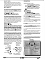
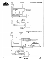
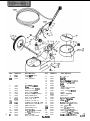
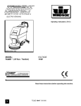
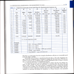
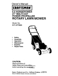
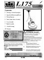
Contents:
1
Warnings - Product Description
2
Operation / Maintenance / Service
4
Wiring Diagrams
5
Motor, Frame, Driver Assembly
6
Cover Assembly
7
Handle Assembly
9
Trouble Shooting
10 Warranty
A
WARNING OF
POTENTIAL INJURY:
This product contains moving parts. To
reduce the risk of injury unplug the
machine before servicing.
Whenever repairs are made ensure electrical
connections are correct and wiring matches
APPROPRIATE diagram before plugging
machine into an electrical outlet.
Record model and serial number located on
data label. Refer to these numbers when calling
Windsor dealer for parts or service.
MODEL :
SERIAL NO. :
PURCHASE DATE :
CAUTION:
See the Owner’s Guide for
1.)
complete operating instructions.
2.)
Maintenance and repairs must only
be done by qualified personnel.
3.)
Using non-Windsor parts to repair
this machine will void the warranty.
0 80110 USA 303-762-1800*FAX3
98116
Rev.1 512/94
OPERATION
INSPECTION
Please carefully unpack and inspect your machine
for shipping damage. Each unit is operated and thoroughly inspectedbefore shipment, and any damage is
the responsibility of the delivering carrier who should
be notified immediately.
CAUTION: For indoor U s e Only.
To prevent possible damage to the floor
when using the Brush optlon, use water or other
approved cleanlng solution while operating.
When using the pad optloln, always keep
the machine moving when In contact with the
ELECTRICAL
This rotary polisher is designed to operate on a standard 15
, amp, 115 volt, 60 hz, AC household curtent. Check that the
voltage shown on the serial number plate is suitable for the
supply available. Voltages below 105 volts or above 125volts
could cause damage to the motor.
NOTE: 230/250 volt 50 hz models are available.
WARNING:
HIGH STARTINQ TORQUE.
HOLD MACHINE FIRMLY WITH BOTH HANDS.
Ensurethat the paddriver or brush is installedcorrectly and in good shape. Install or change pad if necessary
(See Page 3 for detall of Installation).
1.)
GROUNDING INSTRUCTIONS
This appliance must be grounded. If it should malfunction or break down, grounding provides a path of least
resistance for electric current to reduce the risk of electric shock. This appliance is equipped with a cord having an equipment-groundingconductor and grounding
plug. The plug must be insertedinto an appropriateoutlet that is properly installed and grounded in accordance with all local codes and ordinances.
2.) Plugthe machine into a wall outlet as described in the
grounding instructions.
3.) Lower the handle by unlockingthe adjustment handle
and moving the handle into position. Relock the handle
when it is in a comfortable position.
4.) Check to be sure the pad driver or brush is installed
before starting.
WARN1NG:
Improper connection of the equipment-grounding
conductor can result in a risk of electric shock.
Check with a qualified electrician or service person
if you are in doubt as to whether the outlet is properly grounded. Do not modify the plug provided
with the appliance if it will not fit the outlet, have
a proper outlet installed by a qualified electrician.
-
This appliance is for use on a nominal 120-volt circuit,
and has a grounded plugthat looks like the plug in “Fig.
A below. A temporary adaptor that looks like the adaptor in “Fig . C“ below may be used to connect this plug
to a 2-pole receptacle as shown in “Fig. B below, if a
properly grounded outlet is not available. The temporary adaptor should be used only until a properly
grounded outlet (Fig. A) can be installed by a qualified
electrician. The green colored rigid ear, lug, or the like
extendingfrom the adaptor must be connected to a permanent ground such as a properly grounded outlet box
cover. Whenever the adaptor is used, it must be held
in place by a metal screw.
GROUNDING
PROPER GROUNDING
CONNECTION
CONNECTION
USING AN
Grounding Pin
ADAPTOR
\\
floor.
With the switch lock@)rotated forward, squeeze one
of the switch levers, turning the machine on. (These levers
can be operated independently of each other)
5.)
6.) To stop the machine, release the switch lever and
switch lock.
NOTE The machine is equipped with a circuit breaker to
protect the motor in the event an overload condition
occurs. The circuit breaker is located at the bottom of the
switch housing. Push the reset button to restart the machine. If the breaker trips again, correct the cause of overloading before proceeding.
7.) Do not let machine rest on pad. When finishedwith the
machine for the day return handle to the storage position.
Be sure to leave machine in a safe place where there is no
risk of being tipped over.
CONTROLS
I-
Metal Screw
Grounded
Outlet
Rg. A
Tab For Groundina
Screw
-
ADAPTOR
-6
‘
Fig. C
Page 2
/
Grounded Outlet Box
flg. B
NOTE: Adaptors are
not allowed In Canada.
R0v.l
y2/94
L175”
I
.. . .
1
NOTE: In the following instructionsall letter
will be shown in the up-
DAILY MAINTENANCE:
(At the end of each working day):
MAINTENANCE INSTRUCTIONS FOR THE
L175 SERIES OF FLOOR SCRUBBERS
1.
WARNING:Remove machine power cord from electrical
source before making any adjustments or repairs to the
machine. Only qualified maintenance personnel are to
perform repairs.
3.
2.
PADS:
Only standard 1/2 inch thick pads suitable for low
speed burnishing are recommended.
MOTOR
1.
2.
Remove (4) screws holding motor cover to A B S
housing.
Use compressed air to remove lint and dust
accumulation from motor windings.
PAD DR IV ER/B R USH I NSTALLAT10N :
1.
2.
MOTOR-GEAR UNIT ASSEMBLY
1.
2.
Inspect power cord for wear. To prevent electrical
shock replace cords with frayed or cracked insulation
immediately.
Place machine in the storage position.
Check pad condition. Change if soiled or torn,
Lay machine back on the ground, exposing the
underside.
Place pad driver or brush on the motor lug and rotate
clockwise until engaged. To remove, turn Counterclockwise.
Remove (4) bolts holding handle bracket
aside. Lift off plastic motor shroud.
Tip machine back and remove (4) bolts holding brush
cover and gear unit to chassis. Lift out motor and gear
unit assembly.
NOTE: The machine has a vulcanized steel drive coupling
located between the motor and gear unit. The coupling can
usually be replaced by removing the motor cover and lifting
out the armature. If the lower armature bearing remains in
gear unit adapter plate, it will have to be removed from the
gear box
to access the bearing for removal.
3. Remove (4) motor thru bolts
and lift off motor
cover. Remove armature and field from gear unit adapter
plate.
GEAR UNIT
1.
Remove (6) screws from adapter plate.
Use pry bars to seperate gear unit fiom
3. Remove (6) s a w s fnnn gear unit cover.
Remove cover. Repair as needed.
NOTE: The maximum capacity of the gear unit is 10 ozs.
Use gearbox grease Dubois MPG #2 or COOR’s Coorplex
#3.
2.
NOTES:
WHEELS
1.
Remove wheels every 2 to 3 moths. Clean axle an
apply a small amount of silicone lubricant. Reinstall
wheels.
L1%
Rev.1 5/2/94
3
-
SWITCH
115V WIRING DIAGRAM
CIRCUIT BREAKER
fi
I
POWER ON
INDICATOR LAMP
I
I
SWITCH
11
$APACITOR
-
CIRCUIT BREAKER
230V & 250V WIRING DIAGRAM
SWITCH
MO.TOR COVER
w
GUN
b
CAPACITOR
4
20
m
Rev.1 512/94
Ll%
.
Aun.
1
2
3
4
5
6
7
8A
8B
9A
9B
1OA
1OB
11A
11B
12
13
14
15
16
17
18
19
20
21
22
23
z+t 24
L175
25
34171
70335
87016
87025
70329
87067
70083
14608
14561
2007 1
20070
73306
73304
02108
02107
02106
70043
36103
36102
09040
09042
36100
36101
09038
27353
09043
27351
27352
73392
Frame
Screw, 10-32 x 1/2 PHTF
Washer, #lo Star
Washer, 114 Star
screw, 1/4-20 x 314 PHTF
Washer, 5/16 Star
screw, 5/16-18 x 1HHMS
. _ B ~ m p ~L175-17
r,
B u m p . L175-20
clnmp, L175-17
Clamp, L175-20
Shroud. L175-17
Shroud, L175-20
Pad Driver, L175-17
Pad D I ~ v cL175-20
~,
Plate,Clutch L175
Screw, 10-32x 5/8 FHMS
Gear Unit Assembly
Gear, CoverDrive (131T)
Bearing, Drive Cover
Bearing, Motor Lower
Gear. m e t (58-0
Gear, Pinion (13T)
Bearing, Motor Lower
cage. 3 Planet Gear
Bearing, Rotating Cover
Cover, Rotating
coupling
Spacer. B h g
Rev. 1 5/2/94
26
27
28
29A
29B
30A
30B
31
32
33
34
35
36
37
38
39
40
41A
41B
42A
42B
44
45
46
47
48
49A
49B
70353
3609
7035
53179
53180
73391
73393
87013
70354
31060
62262
70323
87105
87106
72064
70234
09039
7207 1
72065
67199
67200
27358
14639
70351
27357
14624
53168
53168
Screw, 10-32 x 314 SHCS
Gear End Shield
Screw, 10-32 x 1.25 SHCS
Motor, 115V w/o Gearbox
Motor, 220-24OV w/o Gearbox
Stator Asm. 115V
stator krm, 220-25ov
Washer, 114 ID x 5/8 OD
Screw. 1/4-28 x 7.50 HHCS
End Shield
Plate,Motor Access
Screw. 10-32 x 114PHTP
Washer, 1.56 OD
Washer, Thrust 1S O OD
Switch, Staionary
Screw, 10-32 x 3B PHST
Bearing, Upper Motor
Switch, Centrifugal 115V
Switch, Centrifugal 220-25OV
Rotor Asm, 11N(w/SW &BRG)
Rotor Asm,220-25OV (w/SW & BRG)
Capacitor, 240V 6OHz 20MFD run
Bracket, Capacitor
Screw, 10-32 x 3/8 HHTF w/star
Capacitor, llOV 6OHz 341 MFD start
Bracket, Capacitor
Motor, ll5V 1.5Hp wKieprbox
Motor.240V 1 S P wKitarbox
5
KEY
PART NO.
DESCRIPTION
1
2A
57040
27331
27355
Nut, 1/2 NPT Conduit
cover, 115v
Cover, 220-25OV
2B
6
7
8
9
10
11
12
13
14
15A
15B
16
17
18
19
20A
20B
6
21
22
73195
70347
70083
87083
7007 1
14603
14532
70177
20069
70330
70482
51114
27340
73307
87086
88445
88553
87067
70345
KEY
PART NO.
DESCRIPTION
23
24
25
26
27
28
29
30
31
32
33
34
35
36
37
38
39
40A
4OB
41
42
43A
43B
66114
36081
41143
57118
03055
89064
87008
87025
70020
38153
50401
27338
70086
57028
87018
70187
57104
88557
88808
70162
87010
23169
23167
Pin, 114 x 1.75
G
e
a
r
m
Shaib Relief. 1/2 NFT
Screw, 1/2-13 x 3 HHCS
Screw, 5/16-18 x 1 H H M S
Washer, 5/16 Split Lock
Screw, 4.40 x 1/2 PHST
Bumper, L175 Handle Bracket
Bracket, Handle Pivot
Screw, 10-32 x 1/2 FHMS
Clamp, Cord
Set Screw, 5/16-18 x 1/2
Set Screw, 5/16-18 x 314 (L175)
Handle Position Lock
Handle Lock Cable
Spring, Polisher Lock
Washer, M10 x 30
Wire Asm, 115V L175 Handle
W i r e A m . 220-25OV L175
Washer. 5/16 Star
Screw, 5/16-18 x 2 SHCS
Rev., 5/2/94
Housing, Handle Pivot w/Hook
Nut, 1/2-13 UNC Nylock
Axle
Wheel
Washer, 1/4 ID x 1.25 OD
Washer, 1/4 Star
screw. 1/4-20 x 1/2 HHMS
Handle
Label, 175 Lightning
Motor Cover
Screw, 10-24 x 1/2 PHMS
Nut, 10-24 li~m
Washer, #lo Flat
Screw, 10-24 x 1/2 PHST -FNut, 10-32 Hex w/ Star washer
Wire. ll5V Ground
Wire, 220-25OV Ground
Screw, 10-32 x 3/8 PHMS
Washer, .578 ID x 1.060 DX .63
Cord Set, 15MM Euro x 50'Blk
cord set, 1413 std x 50' n w .
208
230V 250V
Switch and
Terminal Block Asm
*Use for both sides (2)
7
KEY
PART #
DESCRIPTION
1A
1B
2
3
4
5
6
7A
14700
14312
27558
50649
57024
70384
57006
41234
41246
41244
41243
51188
66187
76ll2
36139
51192
51191
73571
70242
70451
70455
73400
73402
72123
72119
70351
20054
70335
87016
57003
99627
23167
23169
78288
73572 ._
62251
62344
78270
66199
62399
51187
Breaker 15A 25OVAC 50VDC
Breaker, 7A Circuit
Collar, C i t Breaker
Label, Circuit Breaker
Nut, 3/8-27 Panel
S C ~ ,1/4-20 x 1/2 PHTR Pltd.
Nut, 1/4-20 Hex Pltd
Housing, POL Handle (Logo)
Housing, POL Handle Rear Mach’d
Housing, POL Handle Top
Housing, POL Handle Bottom
Lever, Height Polisher Handle
pin, POL Handle
Terminal Block, 3 position
Grip, Handle
Lock,Switch Lt. POL Handle
Lock, Switch Rt. POL Handle
Spring, Handle Lock
Scr, 4-40 x 1/4 PHMS Pltd.
Scr, 1/4-20 x 1.62 SHCS Pltd
Scr, #6-32 x 1.00 P P m Pltd.
Spacer, UL Switch
Spacer, Adj. Handle
Switch, 25A SPST 125-25OV Snap
Switch, Snap POL Handle 230V
Scr, 10-32 x 3/8 HHTR w/SW
Clamp, 318 Nylon W C S A
Scr, 10-32 x 1/2 PHTR Gm/Gmd
Washer, #10 Lock Ext Star SS
Nut, Yellow Wire
Electric Tape, 3/4 w/UL-CSA
Cord Set, 14/3 Std x 50’ Yellow
Cord Set, 1.5mm Euro x 50’ Blk
Tube,Polisher Handle Merit
Spring, Switch Handle
Plate, Handle Lever
Plate, Lever Plug
Tube,Handle Polisher
Pin, Polisher Handle
Plate,Retainer 230V
Lever, Switch Polisher handle
7B
7c
7d
8
9
10
11
12
13
14
15
16
17
18
19
20A
20B
21
22
23
24
25
26
27A
27B
28
29
30
31
32
33
34
35
QTY. NOTES
1
1
1
1
1
4
2
2
1
1
1
1
3
1
2
1
1
2
2
2
2
1
1
1
2
1
1
1
1
1
1
1
1
1
1
1
1
1
2
1
1
All 230V “I” & 250V ‘?A”
Qty.1 on 230V ”I” machines.
Used on 230V ”I” machines only.
Used on 250V “LA” machines
Used on 250V “IA” machines
All 230V “I” & 250V “IA”
Used on ll5V machines only.
A11 ll5V machines.
All 23OV ”I” & 250V “IA”
All ll5V machines.
All ll5V machines.
All ll5V machines.
All 230V ”I” & 250V “IA”
All 230V ”I”
._
8
1M
Rev. 1 5/2/94
1175
TROUBLE SHOOTING CHART :
PROBLEM
POSSIBLE CAUSE
No power to
Dead electrical circuit Check building circuit
breaker or fuse box.
machine
Electrical shock
Power switch failure
Test switch for continuity and replace if
necessary.
Faulty circuit breaker
Replace.
Faulty power cord
Replace.
Equipment not
grounding
Follow grounding instructions exactly.
Receptacle not
grounded
Internal wiring
problem
Circuit breaker
tripping
SOLUTION
Have an electrician inspect building’s
wiring.
Ensure that the machines wiring
matches the appropriate wiring diagram.
Replace any wires or components which
are short circuiting.
Faulty circuit breaker
Test circuit breaker for continuity.
Replace circuit breaker if necessary.
Mechanical problem
Higher amp draws indicate a mechanical
problem, find the parts which are not
moving as freely as they should, and repair
or replace.
NOTES:
TM
LJ75
Rev.1 5/2/94
9