1
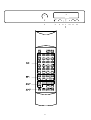
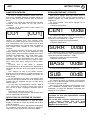
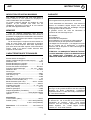
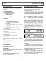
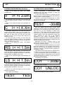
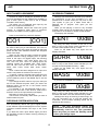
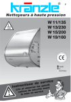
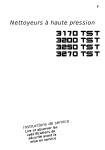
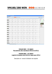
NOTICE D'UTILISATION
3
OWNER'S MANUAL
9
AVP
2
1
3
2
4
5
6
7
8
9
10
11
12
AVP
INSTRUCTIONS
F
Cher Client,
Nous vous remercions pour l'achat de votre AVP Micromega.
Nous vous incitons à une lecture attentive du présent manuel avant de procéder à l'installation
d'AVP.Les diverses informations contenues ci-après sont nécessaires au réglage optimal d'AVP et
vous permettront de tirer le meilleur parti de cet appareil.
VERIFICATION
RACCORDEMENTS
Vérifiez avec attention l’état du carton d’emballage.
Si vous aviez le moindre doute à ce sujet, n’hésitez pas
à contacter votre revendeur.
Après avoir vérifié que la tension secteur d’ AVP
est identique à celle qui dessert votre habitation,
raccordez le cordon secteur au bloc secteur de
l’appareil et à la prise murale.
Raccordez les sorties analogiques de vos sources
Audio-Vidéo aux entrées analogiques d’AVP AN1 et
AN2. Ces entrées décodent les signaux codés en
Dolby Pro-Logic.
Raccordez les sorties numériques de vos sources
Audio-Vidéo aux entrées numériques d’AVP COAX-1,
COAX-2, OPTO-1, OPTP-2. Ces entrées décodent
les signaux en données compressées.
Raccordez le cordon Cinch Stereo entre les sorties
FRONT L+R d’AVP aux entrées de votre amplificateur
principal. Si vous utilisez Minium AMP comme
amplificateur principal, raccordez le cordon Stéréo à
l’entrée AUX2/PRO de Minium AMP.
Si vous possédez un caisson de grave amplifié,
raccordez son entrée à la sortie SUB d’AVP et référez
vous au manuel de votre caisson pour sa mise en
oeuvre.
Si vous avez une enceinte de voie centrale,
raccordez la aux sorties haut parleur CENTER
CHANNEL OUTPUT d’AVP.
Raccordez l’enceinte d’effets arrière gauche aux
sorties haut parleur LEFT SURROUND OUTPUT
d’AVP et l’enceinte d’effets arrière droite aux sorties
haut parleur RIGHT SURROUND OUTPUT.
DEBALLAGE
Retirez avec le plus grand soin votre appareil de son
carton. Nous vous conseillons de conserver la totalité
de l’emballage dans un endroit sûr et sec. Si vous
deviez retourner votre appareil chez votre revendeur, il
vous faudrait impérativement le renvoyer dans son
emballage d’origine car la garantie ne s’applique qu’à
cette seule condition.
ACCESSOIRES
En ouvrant le carton vous trouverez les accesoires
suivants :
• Un cordon secteur.
• Un cordon Cinch Stéréo.
• Une télécommande.
TENSION SECTEUR
Vérifiez que la tension secteur indiquée sur le coté
du carton d’emballage et au dos de l’appareil est bien
la même que celle qui dessert votre habitation.
Dans le cas contraire, veuillez contacter votre
revendeur.
Le connecteur marqué TO EXTERNAL VIDEO
SWITCHER situé à gauche des entrées analogiques
d’AVP se raccorde au boîtier de commutation Vidéo
AVS. Veuillez contacter votre revendeur pour toute
information à ce sujet.
INSTALLATION
Afin de profiter au maximum de tous les avantages
d’AVP il est impératif de suivre les instructions de ce
manuel.
Dans la mesure du possible nous vous
recommandons d'installer AVP sur un meuble hi-fi ou
sur tout autre meuble présentant une ventilation
suffisante.
ATTENTION!
Si pour des raisons esthétiques vous optiez pour
l’empilement de vos appareils, AVP devra
impérativement se trouver sur le dessus de la pile. Ne
placez jamais aucun appareil sur AVP. Il est
recommandé de laisser un espace d’au moins 30cm
au dessus d’AVP. Si vous utilisez Minium AMP
comme amplificateur principal, placez AVP sur une
tablette différente. N’empillez jamais AVP et AMP.
3
AVP
INSTRUCTIONS
FACE AVANT
FACE AVANT (Suite)
Les numéros qui suivent correspondent aux chiffres
placés sur le dessin situé en page 2 de ce manuel.
11 – TOUCHE MODE :
F
Pour accéder aux menus de configuration.
Pour accéder aux réglages fins de chaque canal
Pour accéder aux réglages fins en écoute.
1 - ENCODEUR :
Assure les fonctions suivantes :
♦ Controle de Volume principal.
♦ Ajustage des différents canaux.
♦ Réglage du retard.
♦ Assignation des noms des sources.
♦ Sélection des modes
12 –TOUCHE STANDBY :
Met l’appareil en fonction ou en veille.
MISE SOUS TENSION
Après avoir basculé le commutateur ON/OFF situé
sur le bloc secteur de l’appareil, appuyez sur la
touche STANDBY d’AVP ou sur le bouton AVP de
votre télécommande pour mettre AVP en fonction.
Si vous uilisez Minium AMP comme amplificateur
principal, mettez le en fonction maintenant en vous
référant à son manuel d’utilisation.
Si vous avez choisi de mettre AVP en fonction par
la télécommande, et que votre amplificateur soit un
Minium AMP, ce dernier a reconnu le code d’AVP et
doit indiquer alternativement Au2 In / Pro Y. Vous
devez alors confirmer votre choix en appuyant une
fois encore sur la touche AVP de votre télécommande
et Minum AMP indique alors "Pro On"
Si votre amplificateur principal est d'un autre type,
mettez le en fonction maintenant.
L'afficheur d'AVP indique maintenant:
2 - AFFICHEUR :
L’afficheur indique
♦ En Mode Normal :
• Sur la gauche la source sélectionnée.
• Sur la droite le niveau d’écoute.
♦ En Mode Test :
• Le niveau relatif de chaque canal en
séquence.
♦ En Mode Réglage :
• Le niveau relatif de chaque canal.
3 - LED STANDBY :
La diode Led indique que l’appareil est en veille.
4 – TOUCHE INPUT :
Pour sélectionner les entrées.
CO1
5 – TOUCHE STEREO :
Pour forcer la reproduction en stéréo sur les voies
principales.
- 30dB
Puis après quelques secondes:
CO1 UNLOC
6 - LED DTS :
La diode Led indique que l’appareil décode un signal
DTS.
S'il n'y a pas de signal sur l'entrée COAX-1.
7 - LED DOLBY DIGITAL :
AVP
étant
entièrement
télécommandable,
l'utilisation de la télécommande vous permettra
d'effectuer des réglages optimals à partir de votre
place d'écoute sans avoir à vous déplacer.
Cependant pour les premiers réglages nous vous
conseillons de les faire en utilisant les touches et
l'encodeur de l'appareil .
La télécommande sera mieux appropriée lorsqu'il
s'agira de faire des réglages en temps réel et ce à
partir de votre position d'écoute.
La diode Led indique que l’appareil décode un signal
DOLBY DIGITAL.
8 - LED STEREO :
La diode Led indique que l’appareil est forcé en
Stéréo.
.
9 - LED PRO-LOGIC :
La diode Led indique que l’appareil décode un
DOLBY PRO-LOGIC.
10 - LED MPEG :
La diode Led indique que l’appareil décode un signal
MPEG.
4
AVP
INSTRUCTIONS
F
CONFIGURATION DU SYSTEME
CONFIGURATION DU SYSTEME (Suite)
Vous allez maintenant configurer AVP pour
l'adapter à votre environnement.
Le schéma suivant représente une pièce d'écoute
type équipée d' un système Home Cinéma.
Vous ne devez noter que les distances des
enceintes que vous avez. Si vous n'avez pas de voie
centrale la dimension DIM C est inutile.
Vous êtes prêts à configurer AVP. Pressez la
touche MODE jusqu'à ce que l'afficheur indique:
ECRAN VIDEO
C
L
DIM F
SUB
R
DIM C
NO
Si vous possédez un caisson de grave amplifié
tournez l'encodeur et l'afficheur indique alors:
DIM F
SUB
YES
AVP a pris en compte votre caisson de grave.
Appuyez une fois sur la touche MODE. L'afficheur
indique alors:
LS
DIM LS
ZONE D'ECOUTE
DIM LR
RS
CENT
Pour vous aider à configurer AVP, nous avons
réalisé un petit tableau que nous vous demandons de
compléter avant de commencer la configuration
d'AVP proprement dite. Vous pourrez alors passer à
la configurationde l'appareil.
Si vous N'AVEZ PAS de voie centrale tournez
l'encodeur et l'afficheur indiquera:
CENT
VOTRE SYSTEME EST-IL EQUIPE DE?
CAISSON DE GRAVE AMPLIFIE
OUI
Appuyez une fois encore sur la touche MODE.
L'afficheur indique alors:
NON
SURR
ENCEINTES D'EFFETS
OUI
NO
AVP fonctionne désormais en mode Phantom.
NON
VOIE CENTRALE
OUI
YES
NON
YES
Si vous N'AVEZ PAS d'enceintes d'effets tournez
l'encodeur et l'afficheur indiquera:
DANS VOTRE PIECE D'ECOUTE QUELLES
SONT LES DISTANCES SUIVANTES ?
DIM F = ______m
SURR
exemple : 2.5m or 3.8m
NO
DIM C = ______m
AVP fonctionne désormais en mode 3-STEREO.
DIM RS = ______m
Vous devez maintenant indiquer à AVP les
distances que vous avez mesurées et reportées sur le
tableau. AVP considère que les distances des
enceintes principales à votre point d'écoute sont
identiques.
DIM LS = ______m
5
AVP
INSTRUCTIONS
F
CONFIGURATION DU SYSTEM (Suite)
REGLAGE DES NIVEAUX
Appuyez une fois sur la touche MODE. L'afficheur
indique alors:
F
AVP est équipé d’un générateur de bruit séquentiel
qui permet de régler les niveaux relatifs de chaque
enceinte avec une grande simplicité.
Si vous ne souhaitez pas entrer en mode TEST
tournez l’encodeur pour que l’afficheur indique NO et
appuyez de nouveau sur la touche MODE pour
revenir au mode de fonctionnement normal.
Cependant, nous vous recommandons vivement
de passer par la procédure de Test.
Appuyez de nouveau sur la touche MODE.
L'afficheur indique alors:
I< >I 3.0m
En utilisant l’encodeur, affichez la distance DIM-F
que vous avez reportée sur le tableau des distances.
Appuyez de nouveau sur la touche MODE.
L'afficheur indique alors:
C
I< >I X.Xm
TEST
La valeur par défauf X.Xm est la valeur de DIM-F
que vous venez d’assigner à AVP.
Pour un fonctionnement correct de votre système,
la voie centrale ne peut en aucun cas se trouver à
une distance supérieure à celle de vos enceintes
principales.
Dans tous les cas la distance DIM-F – DIM-C ne
peut être supérieure à 1.5m
En utilisant l’encodeur, affichez la distance DIM-C
que vous avez reportée sur le tableau des distances.
Appuyez de nouveau sur la touche MODE.
L'afficheur indique alors:
Vous pouvez alors ajuster le niveau du
séquenceur de bruit pour obtenir un niveau sonore
confortable. Dès que vous aurez réglé le niveau
optimal une boucle de bruit de 2 secondes par
enceinte commencera par l’enceinte principale
gauche, puis l’enceinte centrale, l’enceinte principale
droite, l’enceinte d’effets arrière droite puis enfin
l’enceinte d’effets arrière gauche. Cette boucle
continuera aussi longtemps que vous l’estimerez
nécessaire pour parfaire un équilibre idéal entre les
différentes enceintes. Le temps de 2 secondes a été
calculé de façon précise et représente le temps
optimal de perception auditive.
Nous vous conseillons de faire ce réglage de
niveau de votre point d’écoute et d’utiliser les touches
Main ∆∇ de votre télécommande.
Vous avez une latitude de réglage de ± 10dB sur
chaque enceinte.
Si vous souhaitez que la séquence soit manuelle,
appuyez une fois sur la touche MODE et passez
d’une enceinte à l’autre par pressions successives sur
la touche MODE.
Lorsque vous estimez avoir atteint le parfait
équilibre, appuyez sur la touche INPUT de la section
AVP de votre télécommande.
L'afficheur indique alors:
RS I< >I 1.5m
En utilisant l’encodeur, affichez la distance
DIM-RS que vous avez reportée sur le tableau des
distances.
Appuyez de nouveau sur la touche MODE.
L'afficheur indique alors:
LS I< >I 1.5m
En utilisant l’encodeur, affichez la distance DIM-LS
que vous avez reportée sur le tableau des distances.
Dans tous les cas la distance (DIM-F – DIM-RS)
ou (DIM-F – DIM-LS) ne peut être supérieure à 4.5m
Appuyez de nouveau sur la touche MODE.
L'afficheur indique alors:
TEST
-30dB
CO1
- 30dB
Puis après quelques secondes:
CO1 UNLOC
YES
AVP est prêt pour un fonctionnement normal.
6
AVP
INSTRUCTIONS
F
NOMS DES ENTREES
REGLAGE PENDANT L’ECOUTE
De façon à simplifier l’utilisation d’AVP nous vous
donnons la possibilité d’affecter à chaque entrée un
nom à partir d’une liste contenue dans la mémoire
d’AVP.
Chaque nom affecté est mémorisé mais peut être
modifié à votre gré autant de fois que vous le
souhaitez.
Appuyez sur la touche INPUT d’AVP jusqu’à ce
que l’afficheur indique :
Bien que le réglage idéal soit obtenu avec la
procédure de test, il est bon de pouvoir accéder à
certains réglages de niveau pendant l’écoute d’un
programme.
En cours d’écoute, vous pouvez appuyer sur la
touche MODE.
L’afficheur indique alors :
CO1
CENT
[CO1]
00dB
En utilisant l’encodeur de l’appareil ou les touches
Main ∆∇ de la télécommande, vous pouvez ajuster le
niveau de la voie centrale de ± 10dB.
Appuyez à nouveau sur la touche MODE.
L’afficheur indique alors :
AVP indique sur la partie gauche de l’afficheur
l’entrée sur laquelle vous vous trouviez avant
d’exercer la pression longue sur la touche INPUT. Ce
nom correspond à celui qui est imprimé sur la face
arrière de l’appareil. Sur la partie droite de l’afficheur
AVP indique entre crochets le nom assigné en
mémoire.
En tournant l’encodeur, les noms entre crochets
défilent affichant tous les noms disponibles pour
chaque entrée. Pour les entrées numériques les noms
suivants sont disponibles : OFF, DVD, DVD1, DV2,
LD, LD1, LD2, CD, CD1, CD2. Pour les entrées
analogiques les noms disponibles sont : OFF, DVD,
DVD1, DV2, LD, LD1, LD2, CD, CD1, CD2, TV, SAT,
SAT1, SAT2, VCR, VCR1, VCR2, AUX, AUX1, AUX2,
GAME.
Lorsqu’un nom a été utilisé, il disparait
automatiquement de la liste des noms disponibles à
l’exception du nom OFF et du nom original de chaque
entrée.
Pour assigner un nom à une entrée suivante,
pressez sur la touche INPUT. Lorsque la sélection est
finie appuyez sur la touche MODE pour revenir en
mode normal.
Si vous assignez le nom OFF à une entrée, cette
entrée ne sera plus présente lors de la sélection des
entrées soit sur l’appareil soit par le biais de la
télécommande.
Si vous avez fait l’assignation suivante : DVD à
CO-1, OFF à CO-2, LD à OP-1, OFF à OP-2, VCR à
AN-1 et SAT à AN-2, la sélection d’entrées sera la
suivante:
DVD puis LD, puis VCR, enfin SAT.
Cette fonction est extrèmement utile lorsque vous
avez un petit nombre de sources.
SURR
00dB
En utilisant l’encodeur de l’appareil ou les touches
Main ∆∇ de la télécommande, vous pouvez ajuster le
niveau des enceintes arrières de ± 10dB.
Appuyez à nouveau sur la touche MODE.
L’afficheur indique alors :
BASS
00dB
si vous n’avez pas de caisson de grave ou
SUB
00dB
dans le cas contraire.
En utilisant l’encodeur de l’appareil ou les touches
Main ∆∇ de la télécommande, vous pouvez diminuer
le niveau de grave de 10dB.
Bien que la plage de réglage soit importante, nous
vous conseillons d’utiliser cette possibilité avec
modération au risque de dégrader l’ensemble des
qualités de votre système.
NOTE : Les valeurs de réglage de la
procédure de test sont considérées comme
valeurs de référence.
De ce fait AVP reviendra systématiquement
à ces valeurs chaque fois que vous
changerez d’entrée ou que vous mettrez
l’appareil en mode Veille.
INDICATION DU SYSTEME DE CODAGE
AVP détecte automatiquement le type de signal
entrant et l’indique au moyen des diodes Led en face
avant de l’appareil.
Si vous envoyez sur AVP un signal stéréo, analogique
ou numérique, il sera décodé comme un signal Pro
Logic sauf si vous appuyez sur la touche STEREO.
7
AVP
INSTRUCTIONS
F
GARANTIE
INDICATION DE NIVEAU MAXIMUM
AVP indique sur l’afficheur que vous avez atteint le
niveau maximum de votre système en remplaçant la
valeur d’atténuation par le mot MAX.
Ce niveau maximum dépend du réglage de votre
système. Si par exemple vous avez lors de
l’installation augmenté le niveau de la voie centrale
par 6db, MAX apparaitra dès –6db.
AVP est garanti 2 ans à partir de sa date d’achat.
Si AVP nécessitait une intervention, vous devriez le
ramener au revendeur auprès duquel vous aviez
effectué votre achat, dans son emballage d’origine
accompagné de la facture d’achat.
La garantie couvre les vices de fabrication à
l’exclusion de tout dommage tel que :
MEMOIRE
Tous les réglages spécifiques ainsi que les
données que vous avez entrées dans AVP lors de la
procédure de réglage sont stockés dans une mémoire
non-volatile qui ne s’efface pas même si l’appareil est
débranché du secteur.
De la même façon à chaque mise sous tension ou
sortie du mode Veille, AVP retrouvera sa dernière
entrée et le niveau auquel il était resté. Cependant,
pour éviter toute mauvaise surprise, AVP reviendra au
niveau –30db si le dernier niveau d’écoute était
supérieur à cette valeur.
- Un accident.
- Une négligence.
- Une erreur de manipulation.
- Une installation non conforme au présent manuel.
- Une intervention par des personnes inhabilitées.
- Les dégats lors du transport. ( Les dégats ne seront
pris en compte par le transporteur à condition
d’effectuer dès la réception du colis endommagé les
réserves d’usage).
ATTENTION : LA GARANTIE S’ANNULE D’OFFICE
SI VOTRE APPAREIL N’EST PAS EXPEDIE DANS
SON EMBALLAGE D’ORIGINE OU SI SON
NUMERO DE SERIE A ETE EFFACE OU MODIFIE
CARACTERISTIQUES TECHNIQUES
Performances Audio Typiques.
Entrées Stereo Analogiques : …….............................2
Niveau d’entrée analogique maximum(rms) : ….......2V
Résolution A/N : …………….…...........................20 bit
Entrées Numériques Coaxiales : …............................2
Entrées Numériques Optiques : . …............................2
Format des entrées numériques : …..............IEC1937
Fréquence d’échantillonage : ……....32 - 44.1 - 48Khz
Résolution N/A : …………..….........................6 x 20bit
Sortie Ligne : ……………............................................3
Impédance de Sortie : …………….……………< 600Ω
Gain Avant (L+R) : …..........................................14 dB
Gain Sub : …….....................................................24dB
Niveau maximum de sortie Ligne (rms) : ……….......5V
Puissance Voie Centrale ( 4Ω ) : ……….............60 W
Bande Passante (40W / 8Ω) : …….......20 Hz - 30 kHz
Puissance canaux Surround ( 4Ω ) : ……….....2x60 W
Impédance de sortie : ………………….. < 0.1 Ω / 1kHz
THD ( 20Hz-20kHz ) : …………….................. < 0.1 %
Réserve dynamique : …………..........................> 15dB
Rapport Signal/Bruit ( Pondéré A) : ……..........> 85 dB
Type de Décodeur : ………..........Dolby Digital / MPEG
Options : ………….................................................DTS
Fabriqué sous licence de Dolby Laboratories. "Dolby",
"Pro-Logic" et le symbole double-D sont des marques
déposées de Dolby Laboratories. Confidential
Unpublished Works. ©1992-1997 Dolby Laboratories,
Inc. Tous Droits réservés.
Alimebtation.
Consommation ( Max ) : …….............................220 W
Fusible ( 5x20 ) : ……….............1.6A / 250V (Retardé)
3.15A / 130V (Retardé)
Fabriqué sous licence de Digital Theatre Systems,
Inc. Brevet US No. 5,451,942 et tout autre brevet
international en instance. "DTS", "DTS Digital
Surround" sont des marques déposées de Digital
Theatre Systems, Inc. ©1996 Digital Theatre
Systems, Inc. Tous droits réservés.
Dimensions : L x P x H en mm : ………430 x 295 x 70
Poids : …...........................................................6.5 kg
8
AVP
INSTRUCTIONS
E
Dear Customer,
Thank you for purchasing Micromega AVP.
Please pay close attention to this instruction manual, and read it fully before attempting to operate
AVP. It is designed to ensure that you maximise your pleasure and familiarise you with its many
unique functions.
CHECKING
CONNECTIONS
Check that the carton has no damage. Should you
have any doubt about its condition, please do not
hesitate to contact your dealer.
Having verified that the mains voltage indicated on
the rear of the unit corresponds to your local power
supply mains voltage, connect the mains leads
provided to the rear of the unit and to the wall sockets.
Connect the analog audio outputs of your AudioVideo sources to the analog inputs of AVP. labelled
AN-1 and AN-2.These inputs handle Analog Stereo
Dolby Pro-Logic encoded signals.
Connect the digital audio outputs of your AudioVideo sources to the digital inputs of AVP. labelled
COAX-1, COAX-2, OPTO-1, OPTO-2.These inputs
handle compressed data encoded signals.
Connect the stereo Cinch-Cinch (Phono) cable
between the front channels outputs labelled FRONT
L + R to the Inputs of your Front channel power
amplifier. If you are using a Minium AMP as main
amplifier, you should connect the cable from the AVP
to the AU2/PRO input of Minium AMP.
If you have an amplified Sub-woofer AVP provides
a suitable output for it. Connect the input of your
amplified Subwoofer to the AVP SUB output
connector and refer to your sub-woofer instruction
manual for adjustment.
If you have a center channel speaker connect it to
the + and - binding posts of the CENTER CHANNEL
OUTPUT terminals.
If you have Surround speakers connect your left
rear speaker to the + and - binding posts of the LEFT
SURROUND OUTPUT terminals and the right rear
speaker to the + and - binding posts of the RIGHT
SURROUND OUTPUT terminals.
UNPACKING
Very carefully remove the unit from the box, taking
care to preserve all the packing material. It is good
practice to put the carton and its contents into an outer
plastic bag and deposit it somewhere safe and dry. In
the unlikely event that your unit needs to be sent back
to either your dealer or distributor, it must be sent in the
original packing material. Failure to observe this will
invalidate your warranty.
ACCESSORIES
Upon opening the carton, you will find:
• Mains lead cable
• Stereo Cinch-Cinch cable.
• Remote control handset
MAINS VOLTAGE
Check that the mains voltage indicated on both the
carton and the rear of the unit correspond to your
local power supply
If you are in any doubt, consult your dealer.
INSTALLATION
In order to obtain the maximum performance of
AVP, it is important to follow the installation
instructions.
Wherever possible, we recommend that AVP be
installed in an audio rack or other suitable furniture
that provides sufficient ventilation.
The Video Extension connector located at the right
hand side of the input connectors is to be used with
AVP optional Video switcher AVS. Please contact
your dealer for more information.
WARNING!
If for aesthetic or ease of use reasons, you choose to
stack the units of your system, it is imperative that you
place AVP on the top. Never place any unit on top of
AVP. We recommend that you provide a space of at
least 30cm above AVP in order to ensure adequate
ventilation. If you are using a Minium AMP as main
amplifier, please place AVP on a separate shelf.
Never place AVP on top of Minium AMP.
9
AVP
INSTRUCTIONS
AVP FRONT PANEL
AVP FRONT PANEL (Continue)
The following numbers refer to the numbers located
on the drawing of the Front panel of AVP on page 2 of
this manual.
11 - STANDBY KEY:
E
To switch the unit in and out of Standby mode.
SYSTEM POWER-UP
1 - ROTARY ENCODER :
After having turned on the ON/OFF switch located
at the rear of the unit press the STANDBY key of the
unit or the AVP key of the Minium system remote
control handset to bring AVP into operational mode.
If you are using a Minium AMP as main amplifier
for the front speakers, you should turn it on now and
put it in Processor mode. (Refer to Minium AMP
owner's manual for this operation).
If you have chosen to turn on AVP with the AVP
key of the remote control handset, and you are using
a Minium AMP as main amplifier, the Minium AMP
has automatically recognised the command and is
now indicating alternatively Au2 In / Pro Y. You should
confirm your request by pressing again on the AVP
key of your Minium remote control handset. Minium
AMP is now indicating "Pro on" in fixed mode.
If you have decided to use another type of
amplifier for the front speakers you should turn on this
amplifier now.
AVP Display now indicates :
Provides the following functions :
♦ Master Volume Control.
♦ Channel trimming.
♦ Delay time adjustment.
♦ Input name assignment
♦ Mode selection
2 - DISPLAY :
The display indicates
♦ In Normal Mode :
• On the left side the selected source.
• On the right side the volume level.
♦ In Test Mode :
• The relative level of each channel in
sequence.
♦ In Adjust Mode :
• The relative level of each channel.
3 - STANDBY LED :
The Led indicator is On when the unit is in Standby.
CO1
4 - INPUT KEY:
To switch between the different inputs.
- 30dB
and after a few seconds:
5 - STEREO KEY:
CO1 UNLOC
To force the reproduction in Stereo mode
6 - DTS LED :
if there is no signal on the CO-1 input.
The Led indicator is On when the unit has detected
DTS.
With AVP being fully remote controlled, the use of
the remote control handset will ease all operation and
allow you to make more accurate adjustment as you
will be able to do them from your listening position
without having to move back and forth to your
equipment.
The TEST key is the only key that do not have a
corresponding key on the remote control handset.
This has been done on purpose in order to avoid to go
into the test mode by accident.
However for the few first steps of the AVP
configuration it is easier to use the keys and the rotary
encoder directly on the unit itself.
The remote control handset will be mostly useful
when you will need to make adjustment in real time.
Off course, in normal use, the remote control
handset will be always more convenient to control
AVP from the center of the viewing area.
7 - DOLBY DIGITAL LED :
The Led indicator is On when the unit has detected
DOLBY DIGITAL signal.
8 - PRO-LOGIC LED :
The Led indicator is On when the unit has detected
DOLBY PRO-LOGIC signal.
.
9 - MPEG LED :
The Led indicator is On when the unit has detected
MPEG Multichannel signal.
10 - MODE KEY:
To access the configuration menus.
To access the trimming function for each output.
To access In session trimming.
10
AVP
INSTRUCTIONS
E
SYSTEM CONFIGURATION
SYSTEM CONFIGURATION (Continue)
You are now going to configure AVP to match your
actual equipment.
The following represent a typical room layout for
5-channel sound.
You are now ready to start configuring AVP. Press
on the MODE key until the display is indicating:
SUB
VIDEO SCREEN
C
L
DIM F
If your system is fitted with an amplified SubWoofer, turn the rotary encoder and the display will
then indicate:
R
DIM C
NO
SUB
DIM F
YES
AVP is now set for Sub-woofer operation.
Press on the Mode key again. The display now
indicates:
LS
DIM LS
VIEWING AREA
DIM LR
CENT
RS
YES
If you DO NOT HAVE a center speaker, turn the
rotary encoder and the display will indicate:
Before you start with AVP configuration we have
made a little chart to help you define the parameters
required by AVP to adapt to your system. You must fill
in the boxes below depending upon you system
configuration and after having fully completed the
information required you will then proceed with the
configuration.
CENT
NO
AVP is now set for Phantom mode operation.
Press on the Mode key again. The display now
indicates:
IS YOUR SYSTEM EQUIPED WITH?
AMPLIFIED SUB-WOOFER
YES
SURR
NO
CENTER SPEAKER
YES
NO
If you DO NOT HAVE Surround speakers, turn the
encoder and the display will indicate:
SURROUND SPEAKERS
YES
YES
NO
SURR
FROM YOUR ROOM LAYOUT WHAT ARE THE
FOLLOWING DISTANCES IN METERS?
NO
AVP is now set for 3-STEREO mode operation.
DIM F = ______m
You must enter now the measured distances from
the center of the viewing area to each of the speakers
of your system. AVP is set-up in such a way that it is
assumed that DIM-F is equal for left and right Front
speakers.
AVP will only ask you to enter the distances of the
speakers that are present in your system. If you DO
NOT HAVE a center speaker DIM-C is irrelevant.
exemple : 2.5m or 3.8m
DIM C = ______m
DIM RS = ______m
DIM LS = ______m
11
AVP
INSTRUCTIONS
E
SYSTEM CONFIGURATION (Continue)
SYSTEM LEVELS ADJUSTMENT
Press on the Mode key again. The display
indicates now:
AVP incorporates a semi-automatic noise
sequencer that has been designed to make this
adjustment remarkably easy.
If you do not want to enter the Test then turn the
Rotary encoder to get NO and press the Mode key
again to revert to normal operation.
However, we strongly recommend that you enter
the Test procedure. Press on the MODE key and the
display will now indicate:
F
I< >I 3.0m
By using the rotary encoder, you will enter the
measured distance noted as DIM-F in the previous
chart.
Press on the mode key again and the display will
indicate:
C
TEST
I< >I X.Xm
You can adjust now the level of the noise
sequencer until you reach the appropriate level for
your system. You will only be able to reach –10db, as
AVP will give you the possibility to adjust each
channel by ± 10db. Right after the correct level will
have been set a 2 seconds noise sequence on each
speaker starts by Front left, followed by Center and
going clockwise on each one of the speakers
according to your system configuration. The 2
seconds is the optimum value for the ear to remember
the last level and to perceive most accurately the level
difference between two channels.
Whenever you enter a different level on one
channel this new level will stay on for 2 seconds and
the sequence will then resume.
You can stop the automatic sequencer by a single
press on the Mode key. The sequencer stops where it
was and you have then the possibility to move from
channel to channel in clockwise mode by pressing on
the Mode key again.
The relative level of each channel is adjusted using
the Main ∆∇ keys on the remote control handset.
Once the perceived level from the center of the
viewing area is equal on all channels you may exit the
noise test sequence in pressing on the input key of
the remote control handset.
The display now indicates :
The default value X.Xm is the value you had just
entered as the DIM-F value for your system. For
proper operation the Center speaker SHOULD NOT
BE more far away than the front left and right
speakers are but can be closer than these by a
maximum of 1.5m.
By using the rotary encoder, you will enter the
measured distance noted as DIM-C in the previous
chart. As explained this distance should vary between
DIM-F and DIM-F minus 1.5m.
Press on the Mode key again. The display
indicates now:
RS I< >I 1.5m
By using the rotary encoder, you will enter the
measured distance noted as DIM-RS in the previous
chart. For proper operation this distance should vary
between DIM-F and DIM-F minus 4.5m.
Press on the mode key again and the display will
indicate:
LS I< >I 1.5m
CO1
By using the rotary encoder, you will enter the
measured distance noted as DIM-LS in the previous
chart. For proper operation this distance should vary
between DIM-F and DIM-F minus 4.5m.
- 30dB
and after a few seconds:
CO1 UNLOC
Press on the mode key again to enter the level
adjustment procedure.
The display now indicates:
TEST
-30dB
AVP is now ready for normal operation.
YES
12
AVP
INSTRUCTIONS
E
INPUT NAMES ASSIGNMENT
IN SESSION TRIMMING
However in order to simplify the operation of AVP
we have embedded into the software the possibility to
give to each input a name from a list of names
included in AVP memory.
This allows you to designate each input by the
name of the equipment attached to it.
A list of standard names that covers the great
majority of equipment types used in consumer
electronics is loaded into AVP program memory.
Although you will reach an ideal set-up by following
the instructions of the Test procedure it is very
possible that in certain cases you may wish to trim
your system to give you a better result with a
particular film or program. AVP gives you this
possibility.
While you are playing a movie or any encoded
material, press one time on the Mode key on the AVP
front panel or on the Minium remote control handset.
The display now indicates :
Press on the INPUT key until AVP displays:
CO1
CENT
[CO1]
00dB
By using the rotary encoder of the unit or the
Main ∆∇ keys of the remote control handset you can
trim the Center speaker level by ± 10dB.
Press on the Mode key once again and the
displays indicates :
If you were on a different input, AVP will indicate
the name of the input you had selected. The name on
the left is the name of the input as printed on the back
panel and the name between brackets the assigned
name of this input.
When you turn then the rotary encoder the names
between brackets change assigning then a specific
name to this input. For Digital inputs, the following
names are available : OFF, DVD, DVD1, DV2, LD,
LD1, LD2, CD, CD1, CD2. For Analog inputs the
following names are available OFF, DVD, DVD1,
DV2, LD, LD1, LD2, CD, CD1, CD2, TV, SAT, SAT1,
SAT2, VCR, VCR1, VCR2, AUX, AUX1, AUX2,
GAME.
Once a name has been assigned to an input, this
name is not present in the list for the next input.
To assign a name to another input press the input
key again and the next input will be displayed. Once
you are finished, press on the MODE key to exit the
procedure.
If you assign the OFF name to any input, this input
will not be selected anymore when you select the
different inputs via the unit or the remote control
handset INPUT key.
For example, if you had assigned DVD to CO-1,
OFF to CO-2, LD to OP-1, OFF to OP-2, VCR to AN-1
and SAT to AN-2, the input selection will display :
DVD then LD, then VCR, then SAT.
This function is extremely useful when you have a
small number of inputs.
SURR
00dB
By using the rotary encoder of the unit or the
Main ∆∇ keys of the remote control handset you can
trim the Surround speakers level by ± 10dB.
Press on the Mode key once again and the
displays indicates :
BASS
00dB
if you have no amplified Sub-woofer or
SUB
00dB
By using the rotary encoder of the unit or the
Main ∆∇ keys of the remote control handset you can
trim down the Bass or the Sub-woofer level by 10dB.
Although the range of trimming is rather large, we
can only encourage you to use this feature with
moderation, as the overall sounding results will be
affected by this trimming.
DECODING SYSTEM INDICATION
AVP automatically detects the type of signal present
at the different inputs and displays this on the system
indicators located between the keys of the Front
panel.
If you feed AVP with a pure Stereo signal you have
the possibility to listen in Stereo mode by pressing on
the Stereo key.
NOTE : The Test procedure values are
considered as Reference values. The unit will
automatically revert to the Test procedure
values any time you enter the Standby mode
or when you change Input.
13
AVP
INSTRUCTIONS
E
WARRANTY
MAX LEVEL INDICATION
AVP indicates on its display that you have reached
the maximum level of your system by replacing the
attenuation indication (e.g. –8db) by the word MAX.
This MAX indication depends of your set-up
configuration. If, for instance, you have raised any of
the channels by +3db the MAX indication will come as
soon as you will reach the step following –4db.
Micromega S.A. warrant the product contained herein
to be guaranteed against manufacturing faults and
defects for a period of 2 years from the purchase
date.
For warranty work the unit must be returned to the
vendor with a copy of the original sales receipt.
MEMORY
All of your specific adjustments as well as all of
your different set-ups are automatically stored in an
EEPROM that keeps them intact even if AVP is
disconnected from the mains.
At power-on or when you come out of standby
AVP will recover the input and the volume that were
set during your last listening session. If the volume
was below -30dB, AVP will revert the volume level
previously set and if the volume was above -30dB,
AVP will revert to -30dB in order to avoid any too loud
unexpected reproduction.
The warranty will be invalid should the unit be :
- Damaged by accident.
- Damaged by negligence.
- Damaged by miss - use.
- Damaged by miss - installation.
- Damaged by tempering by a non - appointed agent.
- Damaged by transit.
You should contact your vendor in your country of
purchase with regards to specific local warranty
details.
AVP TECHNICAL CARACTERISTICS
Typical Audio Performance.
Stereo Analog Inputs : ..............................................2
Maximum analog input level (rms): ........................2V
Analog A/D resolution : ......................................20 bit
Coaxial Digital Inputs : .............................................2
Optical Digital Inputs : ..............................................2
Digital Input Format : ....................................IEC1937
Digital input sampling frequency : ....32 - 44.1 - 48Khz
D/A resolution : .............................................6 x 20bit
Line-out audio Outputs : ........................................... 3
Output impedance : ........................................ < 600Ω
Front Gain (L+R) : .............................................14 dB
Sub Gain : ..........................................................24 dB
Maximum line output level (rms): ...........................5V
Center channel power ( 4Ω ) : ........................... 60 W
Bandwidth (40W / 8Ω) : ...................... 20 Hz - 30 kHz
Surround channels power ( 4Ω ) : .................. 2x60 W
Output impedance( all amplifiers) : ...... < 0.1 Ω / 1kHz
THD ( 20Hz-20kHz ) ( all outputs) : ................ < 0.1 %
Power Headroom : .......................................... > 15dB
Signal to noise ratio "A weighted" : ................ > 85 dB
Decoder type : ..........................Dolby Digital / MPEG
Options : .............................................................DTS
Manufactured under licence from Dolby Laboratories.
"Dolby", "Pro-Logic" and the double-D symbol are
trademarks of Dolby Laboratories. Confidential
Unpublished Works. ©1992-1997 Dolby Laboratories,
Inc. All rights reserved.
Power supply.
Power consumption ( Max ) : ........................... 220 W
Fuse type ( 5x20 ).................. 1.6A / 250V (Slow blow)
3.15A / 130V (Slow blow)
Manufactured under licence from Digital Theatre
Systems, Inc. US Pat No. 5,451,942 and other worldwide patents issues and pending. "DTS", "DTS Digital
Surround" are trademarks of Digital Theatre Systems,
Inc. ©1996 Digital Theatre Systems, Inc. All rights
reserved.
Dimensions : W x D x H in mm .......... 430 x 295 x 70
Weight : .......................................................... 6.5 kg
14
N° DE SERIE / SERIAL NUMBER
1, Rue VERMONT, 78700 CONFLANS STE HNE, FRANCE
TEL: 33(0)1 3490 2503
FAX : 33(0)1 3919 8323