Download Runco LIGHTSTYLE LS-HB Specifications

Transcript
I NSTALLATION/ O PERATION M ANUAL
LS-HB
LS-HB Ultra
High-Brightness, Full-HD Home Theater Projector
RuncoCare™ Standard Two Year Limited
Warranty
Congratulations on your purchase of a Runco® product! With proper installation, setup and care, you should enjoy many years
of unparalleled video performance.
Y
This Limited Warranty is provided free of charge by Runco International, LLC (“Runco”) with the purchase of a covered Runco
product. This Limited Warranty is applicable to all Runco projectors, processors, LCD display and plasma display products,
with the exception of the following models: XP-103DHD, SC-1 and SC-1a1. This Limited Warranty applies to purchases of
covered Runco products occurring on or after June 1, 2011.
EL
IM
IN
A
R
RuncoCare™ Limited Warranty Coverage
Runco warrants its products to be free from defects in material and workmanship during the warranty period provided below. If
a product proves to be defective in material or workmanship during the warranty period, Runco will repair the product, replace
the product with a substantially similar new or like-new product, or refund a prorated share of the purchase price (calculated
based on the remainder of the warranty period and the then-current, most-recent MSRP2 of a similar product), if repair or
replacement of the product is determined by Runco to not be feasible.
Length of RuncoCare™ Warranty Period
PR
Runco products are warranted for two (2) years from the date of shipment from Runco. Lamps are warranted six (6) months
from the date of shipment or 1000 hours of use, whichever comes first. A replacement lamp is warranted for the remaining
portion (if any) of the original warranty period or ninety (90) days from the date it was shipped to you, whichever is longer. All
other accessories, which include but are not limited to cables, remotes, carrying cases, lens cap and other peripherals sold
with the Runco product, are warranted for ninety (90) days from the date of shipment.
RuncoCare™ Eligibility
This Limited Warranty is valid only in the country where the Product was originally purchased and for the buyer who originally
purchased the covered product from the authorized Runco dealer or distributor. This warranty is not transferable; it is not valid
for any subsequent buyer (if any). You may be required to provide proof of purchase in order to receive warranty services.
1. Runco may update this list of products excluded from this warranty from time to time at Runco’s sole discretion, but updates will
not apply on a retroactive basis.
2. MSRP is defined as the most recent product price listed on Runco’s price list.
Runco LS-HB/LS-HB Ultra Installation/Operation Manual
iii
RuncoCare™ Standard Claim Procedure
• In the event of a product defect, please follow the claim procedure provided below:
A. Register your product if you have not yet done so. Visit http://www.runco.com/support/product-registration/ to
register the product.
B. Contact your original authorized dealer or distributor who sold the product.
C. The dealer/distributor will contact Runco Technical Support via email at [email protected] or via phone at 1-80023-RUNCO (1-800-237-8626).
• The dealer/distributor will provide to Runco proof of purchase, serial number, product model number, description of the
problem and any troubleshooting steps already attempted.
EL
IM
IN
A
R
Y
• Runco’s technical support staff will attempt to assist the dealer/distributor in troubleshooting any technical issues that might
be causing the product to malfunction. If Runco is unable to resolve the problem through troubleshooting, a Return Material
Authorization (RMA) number will be issued for the exchange of the defective product if it is determined that the claim is
covered by the warranty. Once an RMA has been created, RMA status is available at [email protected].
• If an RMA is issued, the dealer or customer will need to return the defective product to the Runco repair depot location
specified by the Runco technical support representative. The dealer or customer will need to properly package the defective
product in a suitable shipping container consisting of the product only, and not include any accessories (e.g., cables,
remotes, carrying cases, lens, lens cap and other peripherals). Boxes may be purchased from a Runco technical support
representative.
• The dealer or customer is responsible for paying freight charges and insurance to ship the defective product to the Runco
repair depot location. If there are any shipping damages, the dealer or customer will need to address and resolve any
shipping damage claims directly with the shipping company.
• Runco will not accept a returned product unless an RMA has been issued by Runco.
• For in-warranty repairs, Runco will pay freight charges to return the repaired/replacement product to the dealer/distributor
from the Runco repair depot. For select countries or geographies Runco will ship via an economy express service. Return
delivery time and availability may vary based on origin and destination, and Runco is unable to deliver to PO Box and FPO
Box addresses.
PR
• Note: in the 48 contiguous United States, other options for on-site service or advance exchange for the product may apply,
if you purchased the Runco PremierCare™ Service Plan.
What to Include with Your Return
1. Return only the defective product with the lamp (if applicable).
2. Runco will not be responsible for returning or replacing any accessories (e.g., cables, remotes, carrying cases, lens, lens
cap and other peripherals sold with the Runco product) that are returned with the defective product.
3. Repaired or replacement products will be shipped with a lamp (if applicable) but without any accessories.
RuncoCare™ Warranty Exclusions
This Limited Warranty does not include and is limited by the following:
1. Products not purchased from an authorized Runco dealer
2. Rental costs incurred by the customer in the event of product defect or failure
3. Any product with a defaced, modified, or removed serial number
iv
Runco LS-HB/LS-HB Ultra Installation/Operation Manual
4. Damage, deterioration, or malfunction resulting from:
A. Accident, abuse, misuse, neglect, improper ventilation, fire, water, disaster, lightning, or other acts of nature, smoke
exposure (cigarette or otherwise), unauthorized product modification (including use of an unauthorized mount), or
failure to follow instructions supplied with the product
B. Repair or attempted repair by anyone not authorized by Runco
C. Any damage to the product due to shipment
D. Removal or installation of the product
E. Causes external to the product, such as electric power fluctuations or failure
F. Use of supplies or parts (including lamps) that are not purchased from Runco or do not meet Runco’s specifications
Y
G. Normal wear and tear
EL
IM
IN
A
R
H. Expected lamp degradation and normal decrease in lamp output over a period of time or as the lamp is consumed
I.
Customer caused defects, including but not limited to, scratched/defaced/altered plastics
J.
Failure to follow maintenance procedures as outlined in the product’s user guide where a schedule is specified for
regular cleaning of the product
K. Opening the product and/or tampering with internal circuitry
L. Products lost, stolen or discarded
M. Any damage or dissatisfaction associated with latent images, “burnin,” or any other damage determined by Runco to
be the result of customer use patterns
N. Any other cause, which does not relate to a product defect in material or workmanship
5. Removal, installation, and set-up service charges are excluded from the warranty.
6. Black uniformity issues or other LCD issues associated with usage outside the Runco recommended guidelines and
specifications for the product.
PR
7. Bright or dark sub pixels that are characteristic of LCD technology and considered by Runco to be acceptable and within
Runco’s manufacturing specifications.
Specifically, it is not uncommon for one or more sub pixels to become bright or dark during or after the manufacturing
process. A bright sub pixel is one that remains in the on position, and a dark sub pixel is one that appears black or off. The
sub pixels are usually hard to see and will not detract from the display quality or usability at normal viewing distance. The
following are Runco’s criteria for identifying bright or dark sub pixels that would be considered unacceptable: a) the
number of bright or dark sub pixels; b) the location of the bright or dark sub pixels; c) the color of the bright sub pixels; and
d) the Runco model size. If sub pixels have been identified as unacceptable by Runco the LCD will be deemed faulty and
will be replaced if reported within the warranty period.
Other Terms and Conditions
1. If the defective product is not properly packaged and is damaged in transit during its return to Runco, you may be invoiced
for either the repair costs, if repairable, or the MSRP of a replacement product and shipping costs incurred by Runco.
2. The repaired or replaced product will assume the remainder of your original product’s warranty term or 90 days from the
date the repaired or replaced product is shipped, whichever is longer.
3. If a replacement product is sent, the replacement becomes the property of the customer and the defective product
becomes the property of Runco.
Runco LS-HB/LS-HB Ultra Installation/Operation Manual
v
RuncoCare™ Extended Service Options
Runco offers extended and expanded service plans. For information on additional product protection, please ask your
authorized Runco dealer, email [email protected] or call (toll free) (800) 23RUNCO (800-237-8626).
Exclusion of Implied Warranties
Y
RUNCO PROVIDES NO WARRANTIES, EXPRESS OR IMPLIED, EXCEPT THOSE EXPRESSLY PROVIDED IN THIS
DOCUMENT. RUNCO EXPRESSLY DISCLAIMS AND EXCLUDES ALL OTHER WARRANTIES, INCLUDING THE IMPLIED
WARRANTIES OF TITLE, NONINFRINGEMENT, MERCHANTABILITY AND FITNESS FOR A PARTICULAR PURPOSE.
EL
IM
IN
A
R
Limitation of Liability; Exclusion of Damages
RUNCO’S MAXIMUM AGGREGATE LIABILITY IS LIMITED TO THE COST OF REPAIR, REPLACEMENT OR REFUND OF THE
PRODUCT.
RUNCO WILL NOT BE LIABLE FOR DAMAGE TO OTHER PROPERTY OR FOR DAMAGES BASED UPON INCONVENIENCE,
LOSS OF USE OF THE PRODUCT, LOSS OF TIME, LOSS OF PROFITS, LOSS OF BUSINESS OPPORTUNITY, LOSS OF
GOODWILL, INTERFERENCE WITH BUSINESS RELATIONSHIPS, OR OTHER COMMERCIAL OR FINANCIAL LOSS, EVEN IF
RUNCO IS AWARE OF THE POSSIBILITY OF SUCH DAMAGES AND EVEN IF A REMEDY HAS FAILED OF ITS ESSENTIAL
PURPOSE.
RUNCO WILL NOT BE LIABLE FOR ANY CONSEQUENTIAL, INCIDENTAL, INDIRECT, EXEMPLARY, SPECIAL, PUNITIVE OR
ANY OTHER TYPE OF DAMAGES, WHETHER THE CLAIM IS BASED ON CONTRACT, TORT, PRODUCT LIABILITY,
NEGLIGENCE, STRICT LIABILITY OR ANY OTHER LEGAL OR EQUITABLE THEORY.
RUNCO WILL NOT BE LIABLE FOR ANY CLAIM AGAINST THE CUSTOMER BY ANY OTHER PARTY.
PR
Effect of Local Law
This Limited Warranty gives you specific legal rights, and you may have other rights, which vary from locality to locality. Some
localities do not allow limitations on implied warranties and/or do not allow the exclusion of incidental or consequential
damages, so the above limitations and exclusions may not apply to you.
COPYRIGHT AND TRADEMARKS:
© Copyright 2011 Runco International, LLC (“Runco”). This document contains proprietary information protected by copyright,
trademark and other intellectual property laws. All rights are reserved. No part of this manual may be reproduced by any
mechanical, electronic or other means, in any form, without prior written permission of Runco.
The trademarks reproduced in this Runco Owner’s Manual and used on the Runco Products are either owned by Runco or are
licensed by Runco. You may not reproduce or use the trademarks without the prior written consent of Runco.
Runco Products are manufactured under one or more of the following patents: US. Patent 6755540 and Other Patents
Pending.
vi
Runco LS-HB/LS-HB Ultra Installation/Operation Manual
Important Safety Instructions
Thank you for your purchase of this quality Runco video product! For the best performance, please read this manual carefully
as it is your guide through the menus and operation.
1. Read these instructions.
2. Keep these instructions.
3. Heed all warnings.
4. Follow all instructions.
This symbol is intended to alert the user to the presence of
important operating and maintenance (servicing) instructions in the
literature accompanying the appliance.
EL
IM
IN
A
R
CAUTION:
TO REDUCE THE RISK OF ELECTRIC SHOCK
DO NOT REMOVE COVER (OR BACK)
NO USER SERVICEABLE PARTS INSIDE.
REFER SERVICING TO QUALIFIED
SERVICE PERSONNEL.
Y
CAUTION
RISK OF ELECTRIC SHOCK
DO NOT OPEN
WARNING
This symbol is intended to alert the user to the presence of
uninsulated “dangerous voltage” within the product’s enclosure
that may be of sufficient magnitude to constitute a risk of electric
shock.
5. Do not use this apparatus near water.
6. Clean only with a dry cloth.
7. Do not block any of the ventilation openings. Install in accordance with the manufacturer’s instructions.
8. Do not install near any heat sources such as radiators, heat registers, stoves, or other apparatus (including amplifiers) that
produce heat.
PR
9. Do not defeat the safety purpose of the polarized or grounding type plug. A polarized plug has two blades with one wider
than the other. A grounding type plug has two blades and a third grounding prong. The wide blade or the third prong is
provided for your safety. When the provided plug does not fit into your outlet, consult an electrician for the replacement of
the obsolete outlet.
10. Protect the power cord from being walked on or pinched particularly at plugs, convenience receptacles and the point
where they exit from the apparatus.
11. Only use the attachments/accessories specified by the manufacturer.
12. Use only with a cart, stand, tripod, bracket or table specified by the manufacturer or sold with the apparatus.
When a cart is used, use caution when moving the cart/apparatus to avoid injury from tip-over.
13. Unplug this apparatus during lightning storms or when unused for long periods of time.
14. Refer all servicing to qualified service personnel. Servicing is required when the apparatus has been damaged in
any way, such as power supply cord or plug is damaged, liquid has been spilled or objects have fallen into the apparatus,
the apparatus has been exposed to rain or moisture, does not operate normally, or has been dropped.
15. The +12V trigger only outputs 12Vdc signal for triggering. Do not connect to any other power input or output. This could
cause damage to this unit.
16. Keep the packing material in case the equipment should ever need to be shipped.
17. The lamp becomes extremely hot during operation. Allow the projector to cool down for approximately 45 minutes prior to
removing the lamp assembly for replacement.
18. Do not operate lamps beyond the rated lamp life. Excessive operation of lamps beyond rated life could cause them to
explode in rare occasions.
19. Never look directly into the lens when the lamp is on.
Runco LS-HB/LS-HB Ultra Installation/Operation Manual
vii
Compliance Information
DECLARATION OF CONFORMITY:
Manufacturer’s Name: Runco International, LLC
Manufacturer’s Address: 1195 NW Compton Drive, Beaverton, OR 97006-1992
hereby declares that the Products’ Model Numbers:
EL
IM
IN
A
R
conform with the provisions of:
Y
LS-HB and LS-HB Ultra
Council Directive 2004/108/EC on Electromagnetic Compatibility;
EN 55022 “Limits and methods of measurements of radio interference characteristics of information technology equipment”
1998;
EN 55024 “Limits and methods of measurements of immunity characteristics of information technology equipment” 1998;
Including:
• EN 61000-4-2 “Electromagnetic compatibility (EMC) Part 4: Testing and measurement techniques Section 2:
Electrostatic discharge immunity test”
• EN 61000-4-3 “Electromagnetic compatibility (EMC) Part 4: Testing and measurement techniques Section 3: Radiated,
Radio-Frequency, Electromagnetic Field Immunity Test”
• EN 61000-4-4 “Electromagnetic compatibility (EMC) Part 4: Testing and measurement techniques Section 4: Electrical
fast transient/burst immunity test”
PR
• EN 61000-4-5 "Electromagnetic compatibility (EMC) Part 4: Testing and measurement techniques Section 5: Surge
immunity test"
• EN 61000-4-6 "Electromagnetic compatibility (EMC) Part 4: Testing and measurement techniques Section 6: Conducted
disturbances induced by radio-frequency fields immunity test"
• EN 61000-4-8 "Electromagnetic compatibility (EMC) Part 4: Testing and measurement techniques Section 8: Conducted
disturbances induced by power frequency magnetic fields immunity test"
• EN 61000-4-11 "Electromagnetic compatibility (EMC) Part 4: Testing and measurement techniques Section 11: Voltage
dips, short interruptions and voltage variations immunity tests"
And:
• EN 61000-3-2 "Electromagnetic compatibility (EMC) Part 3, Section 2: Limits for harmonic current emissions (equipment
input current up to and including 16 A per phase)" 2000;
• EN 61000-3-3 "Electromagnetic compatibility (EMC) Part 3, Section 3: Limitations of voltage changes, voltage
fluctuations and flicker in public low-voltage supply systems, for equipment with rated current up to and including 16 A
and not subject to conditional connection" 1995;
Council Directive 2006/95/EC and amended by M1 and C1 on Low Voltage Equipment Safety;
EN 60950 “Safety of information technology equipment, including electrical business equipment”
The Technical Construction file required by this Directive is maintained at the corporate headquarters of Runco International,
LLC, located at 1195 NW Compton Drive, Beaverton, OR 97006-1992.
Date of Declaration: October 2011
viii
Runco LS-HB/LS-HB Ultra Installation/Operation Manual
FCC PART 15:
NOTE: This equipment has been tested and found to comply with the limits for a Class B digital device, pursuant to Part 15 of
the FCC Rules. These limits are designed to provide reasonable protection against harmful interference in a residential
installation.
• Reorient or relocate the receiving antenna.
EL
IM
IN
A
R
• Increase the separation between the equipment and receiver.
Y
This equipment generates, uses and can radiate radio frequency energy and, if not installed and used in accordance with the
instructions, may cause harmful interference to radio communications. However, there is no guarantee that interference will not
occur in a particular installation. If this equipment does cause harmful interference to radio or television reception, which can be
determined by turning the equipment off and on, the user is encouraged to try to correct the interference by one or more of the
following measures:
• Connect the equipment into an outlet on a circuit different from that to which the receiver is connected.
• Consult the dealer or an experienced radio/TV technician for help.
INDUSTRY CANADA (ICES-003):
This Class B digital apparatus complies with Canadian ICES-003.
Cet appareil numérique de la classe B est conforme à la norme NMB-003 du Canada.
PRODUCT DISPOSAL:
PR
The Product contains small amounts of tin, lead and/or mercury. Disposal of these materials may be regulated due to
environmental considerations.
IMPORTANT RECYCLE INSTRUCTIONS
Lamp(s) inside this product contain mercury. This product may contain other electronic waste that can be
hazardous if not disposed of properly. Recycle or dispose in accordance with local, state, or federal Laws.
For more information, contact the Electronic Industries Alliance at WWW.EIAE.ORG.
For lamp specific disposal information check WWW.LAMPRECYCLE.ORG.
DISPOSAL OF OLD ELECTRICAL AND ELECTRONIC EQUIPMENT (Applicable throughout the European
Union and other European countries with separate collection programs)
This symbol found on your product or on its packaging, indicates that this product should not be treated as
household waste when you wish to dispose of it. Instead, it should be handed over to an applicable collection
point for the recycling of electrical and electronic equipment. By ensuring this product is disposed of correctly,
you will help prevent potential negative consequences to the environment and human health, which could
otherwise be caused by inappropriate disposal of this product. The recycling of materials will help to conserve
natural resources. This symbol is only valid in the European Union. If you wish to discard this product, please
contact your local authorities or dealer and ask for the correct method of disposal.
Runco LS-HB/LS-HB Ultra Installation/Operation Manual
ix
PR
EL
IM
IN
A
R
Y
Notes:
x
Runco LS-HB/LS-HB Ultra Installation/Operation Manual
1
Table of Contents
RuncoCare™ Standard Two Year Limited Warranty ................................................... iii
Important Safety Instructions ....................................................................................... vii
Compliance Information .............................................................................................. viii
1. Introduction ...............................................................................................................1
Y
About This Manual .......................................................................................................1
EL
IM
IN
A
R
Target Audience .....................................................................................................1
If You Have Comments About This Manual... ..........................................................1
Textual and Graphic Conventions ...........................................................................1
Using This Manual ........................................................................................................2
Description, Features and Benefits ...............................................................................3
Key Features and Benefits ......................................................................................4
Parts List ................................................................................................................4
2. Controls and Functions ............................................................................................5
LS-HB at a Glance .......................................................................................................5
LS-HB Rear Panel ........................................................................................................9
LS-HB Remote Control ..............................................................................................10
PR
3. Installation ...............................................................................................................13
Remote Control ..........................................................................................................13
Notes on Batteries ................................................................................................13
Notes on Remote Control Operation .....................................................................13
Quick Setup ...............................................................................................................15
Installation Considerations ..........................................................................................16
Installation Type ....................................................................................................16
Ambient Light .......................................................................................................17
Throw Distance.....................................................................................................17
Vertical and Horizontal Position.............................................................................18
Lens Shift .............................................................................................................19
Folded Optics .......................................................................................................20
Other Considerations ............................................................................................20
Runco LS-HB/LS-HB Ultra Installation/Operation Manual
xi
Table of Contents
Installing the Primary Projection Lens (LS-HB Ultra only) .............................................21
Removing the Projector Front Cover .....................................................................21
Installing the Lens .................................................................................................22
Re-Assembling the Projector ................................................................................23
Installing the Optional Anamorphic Lens Mount ..........................................................24
Installing the Movable Anamorphic Lens Transport Assembly ...............................24
Installing the Fixed Anamorphic Lens Base Plate...................................................29
Mounting the LS-HB ..................................................................................................30
Y
Floor Mounting (Upright) .......................................................................................30
EL
IM
IN
A
R
Ceiling Mounting (Inverted)....................................................................................30
Installing the Projector in an Enclosure ..................................................................30
Adjusting the Projection Angle ..............................................................................31
Connections to the LS-HB .........................................................................................32
Connector Panel Access.......................................................................................32
Connecting Source Components to the LS-HB ....................................................33
RS-232 Controller Connection ..............................................................................38
Connecting 12-Volt Trigger Output to External Theater Equipment .......................39
Connecting an External IR Receiver ......................................................................40
Connecting to AC Power ......................................................................................40
Turning on the Power .................................................................................................41
PR
Primary Lens Adjustments ..........................................................................................41
Focus and Zoom ..................................................................................................41
Lens Shift .............................................................................................................41
Changing the OSD Language .....................................................................................42
Adjusting the Picture Orientation ................................................................................42
Rear Projection .....................................................................................................42
Ceiling Mode.........................................................................................................42
Installing and Adjusting the Anamorphic Lens .............................................................43
Fixed Anamorphic Lens ........................................................................................43
Movable Anamorphic Lens ...................................................................................45
xii
Runco LS-HB/LS-HB Ultra Installation/Operation Manual
Table of Contents
4. Operation .................................................................................................................47
Selecting Video Memory .............................................................................................47
Selecting an Aspect Ratio ..........................................................................................47
Selecting An Input Source ..........................................................................................47
Using Picture-In-Picture (PIP) .....................................................................................48
Using the On-Screen Menus ......................................................................................49
Main .....................................................................................................................50
Advanced .............................................................................................................60
Y
System .................................................................................................................64
EL
IM
IN
A
R
Control .................................................................................................................68
Language .............................................................................................................69
Service .................................................................................................................70
5. Maintenance and Troubleshooting ........................................................................73
Lamp Replacement ....................................................................................................73
Troubleshooting Tips ..................................................................................................74
6. Serial Communications ..........................................................................................77
RS-232 Connection and Port Configuration ...............................................................77
Serial Command Syntax .............................................................................................77
Key Commands....................................................................................................77
Operations Commands.........................................................................................80
PR
RS-232 Error Codes .............................................................................................87
7. Specifications ..........................................................................................................89
LS-HB Specifications .................................................................................................89
LS-HB Dimensions .....................................................................................................92
Supported Timings .....................................................................................................93
Runco LS-HB/LS-HB Ultra Installation/Operation Manual
xiii
Table of Contents
PR
EL
IM
IN
A
R
Y
Notes:
xiv
Runco LS-HB/LS-HB Ultra Installation/Operation Manual
1
List of Figures
2-1. LS-HB Front/Side View ................................................................................................5
2-2. LS-HB Rear/Bottom/Top View .....................................................................................7
2-3. LS-HB Rear Panel ........................................................................................................9
3-1. IR Reception Angles ...................................................................................................14
Y
3-2. Estimating Throw Distance .........................................................................................17
EL
IM
IN
A
R
3-3. Projector Placement ...................................................................................................19
3-4. Vertical Lens Shift (Example Only)...............................................................................19
3-5. Folded Optics.............................................................................................................20
3-6. Projector with Fixed Anamorphic Lens Base Plate - Bottom View...............................29
3-7. Mounting Angle Ranges (Side-to-Side and Front-to-Back)..........................................31
3-8. HDMI/DVI Source Connections ..................................................................................33
3-9. RGB Connections ......................................................................................................34
3-10. SCART RGBS Connection .......................................................................................35
3-11. Component Video Connections................................................................................36
3-12. Composite and S-Video Connections.......................................................................37
3-13. RS-232 Control System Connection.........................................................................38
3-14. 12-Volt Trigger Output Connection ...........................................................................39
PR
3-15. External IR Receiver Connection...............................................................................40
3-16. Anamorphic Lens Mounting Assembly - Exploded View ...........................................43
3-17. Attaching the Anamorphic Lens to the Lens Mount ..................................................45
4-1. LS-HB OSD Menu Structure.......................................................................................49
4-2. LS-HB Main Menu......................................................................................................50
4-3. Typical PLUGE Pattern for Adjusting Brightness .........................................................55
4-4. Typical Gray Bar Pattern for Adjusting Contrast ..........................................................55
4-5. Typical Test Pattern for Adjusting Sharpness..............................................................56
4-6. Overscan Examples....................................................................................................58
4-7. Source Select Sub-Menu ...........................................................................................59
4-8. LS-HB Advanced Menu..............................................................................................60
4-9. RGB Adjust Sub-Menu ...............................................................................................62
4-10. Fine Sync Sub-Menu ................................................................................................63
4-11. LS-HB System Menu................................................................................................64
4-12. Source Enable Sub-Menu ........................................................................................65
4-13. PIP and PBP areas for 1080p Display.......................................................................66
4-14. PIP Split-Screen Mode .............................................................................................67
Runco LS-HB/LS-HB Ultra Installation/Operation Manual
xv
List of Figures
4-15. LS-HB Service Menu ................................................................................................70
PR
EL
IM
IN
A
R
Y
7-1. LS-HB Dimensions .....................................................................................................92
xvi
Runco LS-HB/LS-HB Ultra Installation/Operation Manual
Introduction
1. Introduction
This Owner’s Manual describes how to install, set up and operate a Runco LS-HB or
LS-HB Ultra Digital Light Processing (DLP™) Projector. Throughout this manual, both
products are referred to as the “LS-HB,” unless otherwise indicated.
1.1
About This Manual
Runco has prepared this manual to help home theater installers and end users get the
most out of the LS-HB.
Target Audience
EL
IM
IN
A
R
Y
Runco has made every effort to ensure that this manual is accurate as of the date it was
printed. However, because of ongoing product improvements and customer feedback, it
may require updating from time to time. You can always find the latest version of this and
other Runco product manuals on-line, at www.Runco.com.
Runco welcomes your comments about this manual. Send them to [email protected].
If You Have Comments
About This Manual...
Text Conventions: The following conventions are used in this manual, in order to clarify
the information and instructions provided:
Textual and Graphic
Conventions
• Remote and built-in keypad button identifiers are set in upper-case bold type; for
example, “Press EXIT to return to the previous menu.”
• Computer input (commands you type) and output (responses that appear on-screen) is
shown in monospace (fixed-width) type; for example: “To change the aspect ratio to
Letterbox, type op aspect = 1 <Enter>. ”
PR
• All keys with functional names are initial-capped, set in bold type and enclosed in angle
brackets. These keys are the following: <Enter>, <Spacebar>, <Control>,
<Esc> and <Tab>.
• <Enter> indicates that you may press either the RETURN or ENTER key on your
keyboard if it has both keys.
In addition to these conventions, underlining, boldface and/or italics are occasionally used
to highlight important information, as in this example:
Note
A carriage return must be used after each command or string.
Runco LS-HB/LS-HB Ultra Installation/Operation Manual
1
Introduction
Graphic Conventions: These symbols appear in numerous places throughout the
manual, to emphasize points that you must keep in mind to avoid problems with your
equipment or injury:
Note
NOTES emphasize text with unusual importance or special
significance. They also provide supplemental information.
Caution
CAUTIONS alert users that a given action or omitted action can
degrade performance or cause a malfunction.
Y
TIPS highlight time-saving short cuts and helpful guidelines for using
certain features.
EL
IM
IN
A
R
1.2
Using This Manual
Tip
WARNING
WARNINGS appear when a given action or omitted action can result
in damage to the equipment, or possible non-fatal injury to the user.
DANGER!
DANGER appears when a given action can cause severe injury or
death.
Use the following table to locate the specific information you need in this manual.
PR
If you need...
... Turn to page:
Information about obtaining service
iv
General information about the LightStyle™ Series LS-HB/LS-HB
Ultra Home Theater Projector
3
Installation instructions
13
First-time configuration instructions
41
Advanced configuration instructions
60
Troubleshooting tips
74
Specifications for the LightStyle™ Series LS-HB/LS-HB Ultra
Home Theater Projector
89
2
Runco LS-HB/LS-HB Ultra Installation/Operation Manual
Introduction
Elegant and electrifying, the LightStyle™ Series LS-HB/LS-HB Ultra Home Theater
Projector is Runco’s first-ever 1080p projector designed for both performance and
esthetics. Where sleek design encompasses incredible performance, this stylish
combination of legendary Runco engineering and impactful design yield a powerhouse
that elevates the bar for affordable home theater projection.
Designed inside and out by Runco’s award-winning engineering and design team, the
LS-HB incorporates Runco’s proprietary engineering, advanced features and
performance enhancements to achieve an elevated home theater experience.
EL
IM
IN
A
R
Y
The LS-HB is equipped with a precision optics package offering zoom, focus and lens
shift controls and a throw range of 1.89:1 to 2.40:1. For installations requiring shorter
throw distances, the LS-HB is optionally available with a lens that offers a throw range of
1.59:1 to 1.86:1. For installations requiring long throw distances, the LS-HB Ultra is
equipped with a lens that offers a throw range of 2.40:1 to 4.00:1.
To ensure a perfect fit in any room at any time, the LS-HB incorporates the ISF™ (Imaging
Science Foundation) calibration suite for optimal performance in various rooms and
lighting conditions. These calibration tools feature day and night calibration memory
settings, individual sharpness and noise reduction controls, programmable image memory
selection keys, built-in test patterns and a dark room-optimized remote.
Runco’s advanced ViVix™ digital video processing enhances the LS-HB picture quality
and provide artifact-free scaling. Rounding out this impressive projector are discrete input
source, aspect ratio and power on/off, as well as an RS-232 interface for seamless
integration with automation control systems.
PR
For uncompromised widescreen reproduction of movies originally filmed in the
CinemaScope™ 2:35:1 format, the LS-HB can also be paired with one of Runco’s
award-winning anamorphic lens solutions. Through an ingenious combination of software,
electronics and precision anamorphic optics, the Runco anamorphic lens system
maintains constant image height on the screen just as in a movie theater. When a viewer
transitions from 1.78:1 (16:9) program material to superwide 2.35:1, the image simply
gets wider while image height is maintained. The projection system is able to use the full
pixel array, thereby producing a 2.35:1 image with enhanced resolution and increased
brightness. No resolution or image area is lost to those black bars that contain no picture
information.
Note
An anamorphic lens requires the use of a 2.35:1 (or similar aspect ratio),
“superwide” format screen.
Runco LS-HB/LS-HB Ultra Installation/Operation Manual
3
1.3
Description, Features
and Benefits
Introduction
Key Features and Benefits ➤
The LS-HB offers these key features and benefits:
• Native Resolution: 1920 x 1080 (16:9 Native Aspect Ratio)
• DLP system using high-performance Digital Micromirror Device (DMD)
• Customized color wheel produces wide dynamic range and rich grayscale
• Picture in Picture function allows you to display two inputs on the screen at the same
time
• Two (2), HDMI Inputs with High-bandwidth Digital Content Protection (HDCP)
• HDTV Compatible
Your LS-HB is shipped with the following items. If any items are missing or damaged,
please contact your Runco dealer or Runco Customer Service at (800) 23RUNCO.
Y
Parts List ➤
EL
IM
IN
A
R
• LS-HB DLP Projector
• Remote Control Unit and two (2), AA-size batteries
• AC Power Cord (North America)
• 5.0-mm Hex wrench (for lens shift adjustment)
• Runco LS-HB Quick Setup Guide
Optional Accessories:
• Secondary anamorphic lens and lens mount
• Ceiling mount kit (part number 997-4214-00)
• Short-throw lens, 1.59:1-1.86:1
• Long-throw primary lens, 2.40:1-4.00:1 (LS-HB Ultra only)
PR
• Replacement Lamp (part number 997-5268-00)
4
Runco LS-HB/LS-HB Ultra Installation/Operation Manual
Controls and Functions
2. Controls and Functions
2.1
LS-HB at a Glance
Figure 2-1 and Figure 2-2 show the key LS-HB components.
Top IR Sensor
Intake
Vent
Front
IR Sensor
Y
Exhaust Vent
(on side)
EL
IM
IN
A
R
System
Keypad
Power Button/
Status LED
Focus Ring
Projection Lens
Zoom Ring
Figure 2-1. LS-HB Front/Side View
PR
• TOP IR SENSOR
Receives infrared signals from the remote control unit.
• POWER BUTTON/STATUS LED
Indicates projector status as follows:
• Solid green = AC power present, ready to turn on (lamp not lit)
• Flashing green = lamp is warming up or cooling down; keypad functions not allowed
• Off = Lamp lit, projector functioning normally
• Alternating green/red = Lamp problem (door open, unable to strike, end of life), user
intervention likely to fix problem
• Flashing red = Over temperature, user intervention (clear vents, turn on AC) may fix
problem
• Solid red = Error that requires servicing (fan fail, Power-on self-test fail etc.)
• EXHAUST VENT
Warm air exits the projector through this vent. Ensure that it is not blocked.
• FOCUS RING
Rotate this to focus the projected image.
Runco LS-HB/LS-HB Ultra Installation/Operation Manual
5
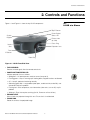
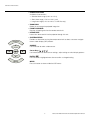
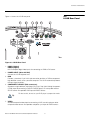
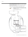
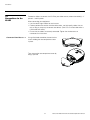
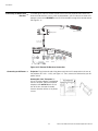
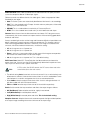
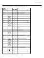
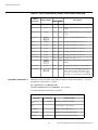
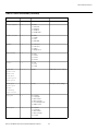
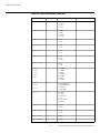
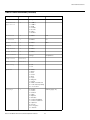
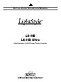
Controls and Functions
• PROJECTION LENS
Available in three versions:
• Standard throw range (1.89:1 to 2.40:1);
• Short throw range (1.59:1 to 1.86:1); and
• Long throw range (2.40:1 to 4.00:1; LS-HB Ultra only).
• ZOOM RING
Rotate this to change the projected image size.
• FRONT IR SENSOR
Receives infrared signals from the remote control unit.
Y
• INTAKE VENT
Internal fans draw cool air into the projector through this vent.
SOURCE
▲
EL
IM
IN
A
R
• SYSTEM KEYPAD
Provides an alternative to using the remote control unit to select a source or navigate
the on-screen display (OSD) controls.
SOURCE
Use this button to select a video source.
◄
►
▲
Cursor Keys ( , , , )
Use these buttons to select items or settings, adjust settings or switch display patterns.
ENTER (
)
Press to select a highlighted menu item or confirm a changed setting.
MENU
Press this button to show or hide the OSD menus.
PR
MENU
6
Runco LS-HB/LS-HB Ultra Installation/Operation Manual
Controls and Functions
3
EL
IM
IN
A
R
2
PR
4
5
Y
1
6
7
Figure 2-2. LS-HB Rear/Bottom/Top View
Runco LS-HB/LS-HB Ultra Installation/Operation Manual
7
Controls and Functions
1. RUNCO LOGO BADGE
Remove to access the vertical
lens shift control.
Y
2. REAR COVER
Remove to access connectors.
Vertical Lens Shift
EL
IM
IN
A
R
3. LAMP MODULE COVER
Remove this cover to access the lamp compartment.
4. CABLE OPENING
Pass cables through this opening.
5. CEILING MOUNT HOLES
Use these to attach the ceiling bracket to the projector. Use M4 screws with a
maximum screw depth of 10 mm (0.39 inch).
6. ADJUSTABLE FEET
Use these when the projector is installed in a table-top configuration to level the image
and/or adjust the projection angle.
PR
7. PROJECTION LENS
The inside of the lens barrel is threaded to accommodate a standard, 72-mm lens
filter. For example, with a smaller screen you can install a neutral-density filter to
reduce the overall light output.
8
Runco LS-HB/LS-HB Ultra Installation/Operation Manual
Controls and Functions
2.2
LS-HB Rear Panel
Figure 2-3 shows the LS-HB rear panel.
HDMI
2
2
S-VIDEO
VIDEO
COMPONENT1 - SCART
Y
IR INPUT
EL
IM
IN
A
R
HDMI
1
1
2
4
RGB
HDMI
1
5
S-VIDEO
12V TRIGGER
6
VIDEO
RS-232
7
COMPONENT1 - SCART
RS-232
12V TRIGGER
HDMI
8
IR INPUT
9
RGB
3
Figure 2-3. LS-HB Rear Panel
PR
1. HDMI 1 (Digital)
HDMI 2 (Digital)
HDCP-compliant digital video inputs for connecting an HDMI or DVI source.
2. POWER INPUT (100 to 240 VAC)
Connect the LS-HB to power here.
3. RGB
Provides a standard, 15-pin VGA-style connection to either an RGB or component
high-definition source, or to a personal computer. The LS-HB automatically detects
the input signal resolution.
4. COMPONENT 1/SCART (RCA connectors)
Standard- or high-definition (480i/480p/576i/576p/720p/1080i/1080p) Component
(YPrPb) input for connecting a DVD/HD-DVD/BD player, HD set-top box or other
SD/HD source. Also provides RGB input for RGBS sources.
For best results, do not run your DVD player in progressive mode.
Tip
5. VIDEO
Standard composite video input for connecting a VCR, laser disc player or other
composite video source. Also provides composite sync input for RGBS sources.
Runco LS-HB/LS-HB Ultra Installation/Operation Manual
9
Controls and Functions
6. S-VIDEO
A standard S-Video input for connecting a DVD player, satellite receiver or Super VHS
(S-VHS) VCR.
7. IR INPUT
Wired input from a Niles- or Xantech-compatible, infrared (IR) repeater system.
8. TRIGGER 1
Provides 12 (+/- 1.5) volt switched output for screen relays with 250mA current
capacity and short protection.
1. ON
Use this button to turn
the projector on.
2. OFF
Use this button to turn
the projector off.
1
PR
3. Source Selection
Buttons (1-5):
Press to select a video
source. By default, these
buttons are assigned as
follows:
1 = HDMI 1; 2 = HDMI 2;
3 = Component;
4 = S-Video; 5 = Video.
However, you can assign
each button to any
source you wish.
4. Cursor Keys
( , , , )
Use these buttons to
select items or settings,
adjust settings or switch
display patterns.
4
6
ON
10
OFF
2
SOURCE
1
2
4
3
5
3
▲
ENTER
▼
5
MENU
USER MEMORY
M1
8
POWER
l
▼
2.3
LS-HB Remote Control
▲
EL
IM
IN
A
R
Y
9. RS-232
A female, 9-pin D-sub connector for interfacing with a PC or home theater
automation/control system.
M2
M3
7
SHARP
GAMMA
OS
NR
PIP
SWAP
LIGHT
9
ENTER
Press to select a
highlighted menu item or
confirm a changed
setting.
10
Runco LS-HB/LS-HB Ultra Installation/Operation Manual
Controls and Functions
5. Aspect Ratio Selection Button
Press this button repeatedly to select one of the following aspect ratios:
16 : 9: For viewing 16:9 DVDs or HDTV programs in their native aspect ratio.
Letterbox: For viewing LaserDisc movies or non-anamorphic DVDs on a 16:9
screen.
4 : 3: Scales the input signal to fit 4:3 sources in the center of the screen.
4:3 Narrow: Scales the input signal to fit 4:3 sources in the center of the screen when
using an anamorphic lens.
Native: Displays source image in its native resolution without re-sizing or overscan.
Y
6. MENU
Press this button to show or hide the OSD controls.
EL
IM
IN
A
R
7. Memory Preset Buttons (M1 / M2 / M3)
Press to recall settings for the current input from one of three memory presets. By
default, these buttons are assigned as follows: M1 = User Memory 1; M2 = User
Memory 2; 3 = ISF Night. However, you can assign each button to any memory
preset you wish.
8. Picture Adjustment Buttons:
PR
Contrast
Press to adjust white level.
Brightness
Press to adjust black level.
Sharpness (SHARP)
Press to adjust sharpness.
Gamma (GAMMA)
Press to select a gamma curve.
Overscan (OS)
Press to select an overscan mode.
Noise Reduction (NR)
Press to adjust noise reduction level.
9. LIGHT
Press momentarily to activate remote backlighting. Press and hold for five (5) seconds
to illuminate the projector rear panel, to facilitate connecting cables in a dark room.
10. Picture-In-Picture (PIP) Controls:
PIP
Press repeatedly to activate/deactivate PIP mode or select the desired PIP image
source.
SWAP
Press to swap the PIP image with the active source image.
Runco LS-HB/LS-HB Ultra Installation/Operation Manual
11
Controls and Functions
PR
EL
IM
IN
A
R
Y
Notes:
12
Runco LS-HB/LS-HB Ultra Installation/Operation Manual
Installation
3. Installation
To install batteries in the remote control:
1. Slide the battery compartment cover in the direction of the arrow to remove it.
3.1
Remote Control
2. Install two AA batteries with the correct polarity.
3.
2.
EL
IM
IN
A
R
1.
Y
3. Replace the cover.
• Make sure that the battery polarities are correct when installing the batteries.
Notes on Batteries
• Do not mix an old battery with a new one or different types of batteries.
• If you will not use the remote control for a long time, remove the batteries to avoid
damage from battery leakage.
• Do not expose batteries to excessive heat such as from sunshine, fire or the like.
PR
• In most situations, you can simply point the remote control at the screen which will
reflect the IR signal from the remote back toward the IR receiver on the projector. In
some cases, however, ambient conditions may prevent this. If so, point the remote
control at the projector and try again.
• If the effective range of the remote control decreases, or it stops working, replace the
batteries with new ones.
• The remote control may fail to operate if the infrared remote sensor is exposed to bright
sunlight or fluorescent lighting.
Runco LS-HB/LS-HB Ultra Installation/Operation Manual
13
Notes on Remote Control
Operation
Installation
• The projector’s front IR receiver has a range of approximately 40 feet (12.19 meters);
the top IR receiver has a range of approximately 20 feet (6.10 meters). Figure 3-1
shows the reception angles of the front and top IR receivers.
EL
IM
IN
A
R
Y
90.0°
90.0°
135.0°
PR
Figure 3-1. IR Reception Angles
14
Runco LS-HB/LS-HB Ultra Installation/Operation Manual
Installation
Table 3-1 gives a quick overview of the LS-HB installation process. The sections following
this one provide detailed instructions.
Note
Installation should be performed by a qualified custom video
installation specialist.
For Details, Refer
to page...
Procedure
EL
IM
IN
A
R
Step
Y
Table 3-1. Installation Overview
Choose a location for the projector
16
2
Install primary projection lens
21
3
Install anamorphic lens mounting assembly (optional)
24
4
Mount the projector
30
5
Connect signal sources to the LS-HB
33
6
Connect external controller to RS-232 port and/or IR repeater
system (optional)
38
7
Connect 12-volt trigger output to retractable screen or other,
+12V trigger-activated equipment (optional)
39
8
Apply power to the projector
40
9
Primary lens adjustments: projected image size (zoom), position
(shift) and focus
19, 41
10
Change the OSD Language (optional)
42
11
For rear-screen and/or ceiling-mount installations, select the
proper picture orientation
42
12
Install and adjust secondary anamorphic lens (optional)
43
50
13
Projector calibration: adjust the following for each input; save
settings when finished:
• Aspect ratio
• Brightness
• Contrast
• Color level
• Tint
• Sharpness
• White Balance
PR
1
Runco LS-HB/LS-HB Ultra Installation/Operation Manual
15
3.2
Quick Setup
Installation
3.3
Installation
Considerations
Proper installation of your projector will ensure the quality of your display. Whether you are
installing a projector temporarily or permanently, you should take the following into
account to ensure your projector performs optimally.
Installation Type ➤
Choose the installation type that best suits your needs: front or rear screen, floor mount or
inverted mount. Table 3-2 compares these various installation methods.
Table 3-2. Projector Installation Options
Considerations
Y
Advantages
EL
IM
IN
A
R
Front Screen, Floor Mount Installation
• Easy to set up
• Can be moved or changed quickly
• Easy to access
• Shares floor space with audience
Front Screen, Inverted Mount (ceiling) Installation
• Does not take up audience space
• Projector is unobtrusive
• Projector cannot be accidentally moved
• Installation is more permanent
• Projector access is more difficult
Rear Screen, Floor Mount Installation
• Projector is completely hidden
• Projector is easily accessed
• Usually good ambient light rejection
• Requires separate room
• Installation cost is usually higher
PR
Rear Screen, Inverted Mount (ceiling) Installation
• Projector is completely hidden
• Usually good ambient light rejection
• Requires separate room
• Installation cost is usually higher
Rear Screen, Floor Mount with Mirror
• Projector is completely hidden
• Usually good ambient light rejection
• Requires less space behind screen than
other rear screen installations
16
• Requires separate room
• Installation cost is usually higher
Runco LS-HB/LS-HB Ultra Installation/Operation Manual
Installation
In general, minimize or eliminate light sources directed at the screen. Contrast ratio in your
images will be noticeably reduced if light directly strikes the screen, such as when a shaft
of light from a window or floodlight falls on the image. Images may then appear washed
out and less vibrant.
Ambient Light
Throw distance is the distance measured from the front of the projector to the screen.
This is an important calculation in any projector installation as it determines whether or not
you have enough room to install your projector with a desired screen size and if your
image will be the right size for your screen.
Throw Distance
EL
IM
IN
A
R
Y
You can quickly estimate the throw distance by taking the width of the screen and
multiplying it by the lens throw ratio; see Figure 3-2. The result of this calculation tells you
roughly how far back the projector should be positioned from the screen in order to
project a focused image large enough to fill the screen.
Estimating Throw Distance
Throw Distance (TD) =
Screen Width (w) x Lens Throw Ratio
Scr
een
wid
th (
PR
TD
Figure 3-2. Estimating Throw Distance
Runco LS-HB/LS-HB Ultra Installation/Operation Manual
17
w)
Installation
Table 3-3 lists the available LS-HB lens options and their associated throw ratios.
Table 3-3. LS-HB Lens Options and Throw Ratios (Note)
LS-HB + Standard
Lens
1.89 – 2.40
LS-HB +
Standard Lens +
Fixed Anamorphic
Lens
Throw Range in
inches, with
72.6x40.8-inch
(1.78:1) Screen
Throw Ratio
Throw Range in
with
inches, with
Primary
96x40.8-inch (2.35:1)
Lens and
Screen
Anamorphic
Minimum Maximum
Minimum Maximum
Lens
137.21
EL
IM
IN
A
R
(n/a)
174.24
Y
Projector Model
Throw
Ratio with
Primary
Lens Only
LS-HB +
Standard Lens +
Movable
Anamorphic Lens
1.89 - 2.40
137.21
174.24
LS-HB +
Short-Throw
Primary Lens
1.59 - 1.86
115.43
135.04
PR
LS-HB +
Short-Throw
Primary Lens +
Fixed Anamorphic
Lens
(n/a)
LS-HB +
Short-Throw
Primary Lens +
Movable
Anamorphic Lens
1.59 - 1.86
115.43
135.04
LS-HB Ultra
2.40 – 4.00
174.24
290.40
LS-HB Ultra +
Fixed Anamorphic
Lens
LS-HB Ultra +
Movable
Anamorphic Lens
(n/a)
2.40 – 4.00
174.24
290.40
(n/a)
1.89 – 2.40
181.44
230.40
1.42 – 1.80
136.32
172.80
(n/a)
1.59 - 1.86
152.64
178.56
1.19 - 1.40
114.24
134.40
(n/a)
2.40 – 4.00
230.40
384.00
1.80 – 3.00
172.80
288.00
Note: Due to normal manufacturing variances, throw distance can vary by up to +/- 5 percent from
these specifications.
Vertical and Horizontal ➤
Position
Proper placement of the projector relative to the screen will yield a rectangular,
perfectly-centered image that completely fills the screen.
Ideally, the projector should be positioned perpendicular to the screen and in such a way
that the lens center is aligned with either the top or bottom edge of the screen area, and
centered horizontally. See Figure 3-3.
18
Runco LS-HB/LS-HB Ultra Installation/Operation Manual
Installation
Ceiling Installation
Height
Ceiling
Projection Distance
x
Lens Center
Lens Center
Screen
Screen
EL
IM
IN
A
R
Height
Y
Floor Installation
Lens Center
Lens Center
x
Projection Distance
Floor
Figure 3-3. Projector Placement
PR
You can use the lens shift controls on the projector to center the image on the screen.
Lens shift is generally expressed as a percentage of the screen height or width, as shown
in Figure 3-4.
Screen Center
0%
50% Height
Lens Shift
(0.5 x H)
100% Height
Lens Shift
(1.0 x H)
Note: This is a general example of lens shift. Lenses vary in their shift capabilities. No particular
lens or projector is used in this example.
Figure 3-4. Vertical Lens Shift (Example Only)
Vertical Lens Shift — LS-HB: The LS-HB provides up to 25% of upward vertical
lens shift and up to 60% of downward vertical lens shift. For example, with a 100 x
56 inch (1.78:1) screen, you can shift the image up to 14.00 inches (0.36 meters) above or
33.60 inches (0.85 meters) below the screen center.
Runco LS-HB/LS-HB Ultra Installation/Operation Manual
19
Lens Shift
Installation
Vertical Lens Shift — LS-HB Ultra: The LS-HB Ultra provides up to 25% of
upward vertical lens shift and up to 35% of downward vertical lens shift. For
example, with a 100 x 56 inch (1.78:1) screen, you can shift the image up to 14.00 inches
(0.36 meters) above or 19.60 inches (0.50 meters) below the screen center.
1. With no vertical lens shift, the lens center and screen center are
aligned with each other.
Note
2. Vertical shift limits are percentages of the screen height.
In rear-screen applications where space behind the projector is limited, a mirror may be
used to fold the optical path, as shown in Figure 3-5. The position of the projector and
mirror must be accurately set. If you are considering this type of installation, contact your
dealer for assistance.
EL
IM
IN
A
R
Folded Optics ➤
Y
3. Vertical lens shift figures are for ceiling mount
configurations. For floor installations (where the projector is
upright), reverse the up/down vertical lens shift percentages.
Screen
PR
Mirror
Figure 3-5. Folded Optics
Tip
For best performance, always use “first-surface” mirrors in your
rear-projection installation (as opposed to conventional,
“second-surface” mirrors with the reflective surface behind a transparent
substrate such as glass or acrylic).
First-surface mirrors provide a strict reflection without the “ghosting”
effect seen with a second surface mirror, where a faint secondary
reflection could be observed coming from the front surface of the glass.
Other Considerations ➤
Other considerations and tips that can help improve your installation:
• Keep the ambient temperature constant and below 35°C (95°F). Keep the projector
away from heating and/or air conditioning vents. Changes in temperature may cause
drifts in the projector circuitry, which may affect performance.
• Keep the projector away from devices that radiate electromagnetic energy such as
motors and transformers. Common sources of these include slide projectors,
speakers, power amplifiers and elevators.
20
Runco LS-HB/LS-HB Ultra Installation/Operation Manual
Installation
The LS-HB Ultra primary projection lens is shipped separately from the projector. Proceed
as follows to install it:
Removing the Projector
Front Cover
EL
IM
IN
A
R
Y
1. Using a Phillips
screwdriver, remove the
two screws holding the
projector front cover in
place.
3.4
Installing the Primary
Projection Lens
(LS-HB Ultra only)
2. Gently pull the cover away from the projector at
each side to detach it.
PR
3. Remove the cover and set it aside.
4. Remove the foam plug from the lens cavity.
Runco LS-HB/LS-HB Ultra Installation/Operation Manual
21
Installation
Installing the Lens ➤
5. Carefully remove the lens and other installation hardware (in a small plastic bag) from
the shipping container.
6. Remove the rear cap from the lens. This protective cap is only used during shipping to
protect the lens from damage.
7. Remove the front cap from the lens.
EL
IM
IN
A
R
Y
8. Install the spring clip (provided with the lens) on the lens shift adjuster retaining slot, as
shown. The clip reduces backlash in the vertical offset mechanism to keep it from
inadvertently moving after adjustment.
PR
9. Insert the lens into the lens cavity. Ensure that the notch on the vertical lens shift
adjuster mates with the retaining slot on the projector, as shown below. Otherwise,
the adjuster won’t work correctly.
10. Install the two (2), black plastic retaining clips (also provided with the lens) on either
side of the lens cavity. Each clip is held in place with two (2), captive Phillips screws.
The white, plastic standoffs serve as “handles” to make removing the clips easier.
22
Runco LS-HB/LS-HB Ultra Installation/Operation Manual
Installation
Re-Assembling the
Projector
Y
11. Attach the black wire to the stray light shield.
PR
EL
IM
IN
A
R
12. Replace the projector front cover that you
removed in Steps 1 through 3.
Runco LS-HB/LS-HB Ultra Installation/Operation Manual
23
Installation
3.5
Installing the Optional
Anamorphic Lens
Mount
If you are installing a standard LS-HB (without an anamorphic lens), skip this step and
proceed with Mounting the LS-HB (page 30).
If you are installing an LS-HB with a fixed anamorphic lens, proceed with
Installing the Fixed Anamorphic Lens Base Plate (page 29).
EL
IM
IN
A
R
Y
If you are installing an LS-HB with a movable anamorphic lens, proceed
as follows to install the lens mount and transport assembly.
Note
1. Do not install the anamorphic lens yet, only the transport
assembly and/or lens mount. You will install the anamorphic lens
after you install the projector and adjust the primary lens.
2. Some components shipped with your projector may differ slightly
from what is shown in these instructions.
Installing the Movable ➤
Anamorphic Lens
Transport Assembly
Package Contents: The LS-HB movable anamorphic lens mount kit consists of the
following items. Some components shipped with your projector may differ slightly from
what is shown in these instructions. If any items are missing or damaged, please contact
your Runco dealer or Runco Customer Service at (800) 23RUNCO.
• Transport Assembly Attachment Plate
PR
• Attachment plate hardware (screws,
washers and spacers)
• Attachment plate security hooks and
related hardware (chain, chain ends,
nuts and washers)
• Transport Assembly
• Transport mounting hardware
• Lens bracket mounting hardware
• Power supply
• Remote control unit and batteries
24
Runco LS-HB/LS-HB Ultra Installation/Operation Manual
Installation
• Anamorphic lens and mounting bracket
1. Place the projector upside down on a blanket or other soft surface.
EL
IM
IN
A
R
2. Position the attachment plate as shown here.
Y
Attaching the Transport Assembly Attachment Plate:
PR
Attachment Points
for Security Hooks
Attachment Points
for Transport Assembly Attachment Plate
and Ceiling Mount Plate
Runco LS-HB/LS-HB Ultra Installation/Operation Manual
25
Installation
3. If you are mounting the projector on a ceiling: Line up the holes on the Ceiling
Mount Plate (included with the projector ceiling mount kit) with those on the bottom of
the projector and attachment plate.
4. Secure the Transport Assembly Attachment Plate and Ceiling Mount Plate to the
projector using the hardware provided with the attachment plate, as shown.
Caution
1. Do not use the mounting screws provided with the ceiling
mounting kit. Use only the hardware provided with the Transport
Assembly Attachment plate.
EL
IM
IN
A
R
Y
2. DO NOT OVER-TIGHTEN THE SCREWS.
PR
Attachment Points
for Security Hooks
Hardware for Attachment Plate
and Ceiling Mount Plate (4 Places):
Screw, Phillips PH,
M4 x 30mm
Lock Washer
Flat Washer
Ceiling Mount Plate
Attachment Plate
5/8" Nylon Spacer
Projector (bottom)
26
Runco LS-HB/LS-HB Ultra Installation/Operation Manual
Installation
Installing the Anamorphic Lens Transport Assembly: After installing the Transport
Assembly Attachment Plate and Ceiling Mount Plate, proceed as follows to install the
Anamorphic Lens Transport Assembly.
Install Transport Pivot Screw Here
Hardware for Lens Transport Assembly:
Pivot Screw, Phillips PH,
#10-32 x 5/8" (1)
Nut, #10-32 (1)
Lock Washer, #10-32 (1)
Pivot Screw,
as assembled
Attachment
Plate
Transport Assembly
EL
IM
IN
A
R
Screw, Phillips PH,
#6-32 x 3/8" (4)
Y
Flat Washer, #10-32 (1)
Transport Assembly
Attachment Points
1. Position the flat side of the motorized transport against the bottom side of the
Attachment Plate so that the center “M” hole in the Attachment Plate is aligned with
the front recessed transport hole.
2. Insert the #10-32 pivot screw up through the transport and Attachment Plate and
loosely complete the assembly with the corresponding washer, lock washer and nut.
3. Loosely insert the four small 3/8” screws through the four remaining “M” slots through
the top of the Attachment Plate and down into the transport.
PR
4. Separate the Anamorphic Lens and lens bracket. Locate the lens bracket mounting
screws and use them to attach the bracket to the transport assembly. Observe the
sticker on the plate showing the correct sequence for installing and tightening the
screws.
Runco LS-HB/LS-HB Ultra Installation/Operation Manual
27
Installation
Attaching the Security Hooks: To help stabilize and support the added weight of the
Anamorphic Lens and Lens Transport Assembly, the attachment plate includes two
security hooks and related hardware for attaching the front part of the plate to the ceiling
above.
Proceed as follows to attach the security hooks. This requires the following tools and
materials:
• Pliers
• Scissors
EL
IM
IN
A
R
Y
• Ceiling Hooks (not supplied)
1. Install the Plate Hook Assemblies in the
two “H” holes of the Attachment Plate
(see diagram on page 26) with the hook
ends on the ceiling side as shown above.
PR
2. Use pliers to bend the closed hooks apart
just enough to install a Chain End at a
later time.
3. Attach the plate hooks to the ceiling as
described in the section entitled Ceiling
Mounting (Inverted) on page 30.
28
Runco LS-HB/LS-HB Ultra Installation/Operation Manual
Installation
To install the base plate on an LS-HB with a fixed anamorphic lens:
Installing the Fixed
Anamorphic Lens Base
Plate
1. Place the projector upside down on a blanket or other soft surface.
2. Secure the base plate and Ceiling Mount Plate (if used) to the projector with the four,
M4 x 0.7 x 14mm screws provided with the anamorphic lens base plate.
Caution
1. Do not use the mounting screws provided with the ceiling
mounting kit. Use only the hardware provided with the
anamorphic lens base plate.
2 Anamorphic
Lens Base Plate
PR
1 Screw,
Phillips
Pan-Head,
M4 x 0.7 x
14mm (4x)
EL
IM
IN
A
R
Ceiling Mount Plate
(part of Ceiling Mount Kit)
Y
2. DO NOT OVER-TIGHTEN THE SCREWS.
Figure 3-6. Projector with Fixed Anamorphic Lens Base Plate - Bottom View
Runco LS-HB/LS-HB Ultra Installation/Operation Manual
29
Installation
3.6
Mounting the LS-HB
There are several methods for mounting the projector. Depending on your chosen
installation, one method may be more suitable than another.
Floor Mounting (Upright) ➤
For fixed installations, and for those that want the projector out of sight or have a limited
space for projector and audience, you can invert the LS-HB and suspend it from the
ceiling using a specially-designed ceiling mount fixture.
Y
Ceiling Mounting ➤
(Inverted)
In typical front and rear screen installations, the projector can be mounted to a secure and
level surface such as a table or cart. Carts are useful when moving a projector during a
presentation or from site to site. If possible, lock the wheels when it’s in position to prevent
it from being moved during a presentation.
For ceiling installations, use Runco-approved mounting hardware
and M4 screws with a maximum screw depth of 10 mm (0.39 inch).
EL
IM
IN
A
R
Note
Install the ceiling mount kit according to the instructions provided with it.
If you are ceiling-mounting an LS-HB with a movable anamorphic lens: Perform
these additional steps to secure the plate Security Hooks to the ceiling (refer to Attaching
the Security Hooks on page 28).
1. Install ceiling hooks (not supplied) into the ceiling directly above the Plate Hooks. The
ceiling hooks should be small enough to accept a Chain End but strong enough when
installed to each support 40 pounds or more.
2. Attach a Chain End to the Chain and then connect it to one of the ceiling hooks.
PR
3. Cut the Chain to a length equal to or slightly greater than the distance between the
ceiling hook and the corresponding Plate Hook.
Installing the Projector in ➤
an Enclosure
4. Attach a Chain End to the other end of the Chain. Then, use the Chain to connect the
ceiling hook and the Plate Hook.
5. Repeat Steps 2 through 4 for the other ceilling hook/Plate Hook pair.
The projector can also be inverted and placed in an enclosure above and behind the
viewing area. Install four feet on the inside bottom surface of the enclosure on which the
projector can rest. A variety of materials can be used for this purpose (for example, rubber
crutch tips or turntable feet).
30
Runco LS-HB/LS-HB Ultra Installation/Operation Manual
Installation
If the screen is significantly higher or lower than the projector, you can also tilt the
projector at a slight angle. In a ceiling installation, you do this by adjusting the ceiling
mount.
Adjusting the Projection
Angle
For a floor installation, turn the adjustable feet at the bottom of the projector to adjust the
projection angle.
EL
IM
IN
A
R
Y
The projector can be rotated (side-to-side) up to 360 degrees and mounted without it
affecting performance. However, to ensure optimal performance of the lamp, limit the
front-to-back tilt of the projector to ±20 degrees; see Figure 3-7.
± 360º
Figure 3-7. Mounting Angle Ranges (Side-to-Side and Front-to-Back)
PR
If you do this, you may need to vertically shift the image to compensate. For detailed
instructions, refer to Primary Lens Adjustments on page 41.
Runco LS-HB/LS-HB Ultra Installation/Operation Manual
31
± 20º
Installation
3.7
Connections to the
LS-HB
Proceed as follows to connect the LS-HB to your video sources, external controller(s) – if
present – and AC power.
When connecting your equipment:
• Use the correct signal cables for each source.
• For best performance and to minimize cable clutter, use high-quality cables that are
only as long as necessary to connect two devices. (Don’t use a 20-foot cable when a
6-foot cable will suffice.)
Using a flat-blade screwdriver, loosen the two
screws holding the rear compartment cover
in place.
EL
IM
IN
A
R
Connector Panel Access ➤
Y
• Ensure that the cables are securely connected. Tighten the thumbscrews on
connectors that have them.
Then, remove the rear compartment cover by
tilting it upward.
PR
32
Runco LS-HB/LS-HB Ultra Installation/Operation Manual
Installation
Connect your video sources to the LS-HB as shown and described in the sections that
follow.
HDMI/DVI Connections: See Figure 3-8.
S-VIDEO
VIDEO
S-VIDEO
VIDEO
COMPONENT1 - SCART
RGB
HDMI
RGB
2
HDMI
1
PR
2
IR INPUT
COMPONENT1 - SCART
HDMI
EL
IM
IN
A
R
RS-232
12V TRIGGER
1
12V TRIGGER
IR INPUT
HDMI
RS-232
Y
Use the HDMI inputs whenever possible. This ensures the highest
video quality because the signal is carried in the digital domain
throughout the entire signal path, from source component output
into the projector.
Tip
HDMI
AV OUT
HDMI
AV OUT
HDMI/DVI sources (BD, DVD,
DTV Set-Top Box, Game Console etc.)
Figure 3-8. HDMI/DVI Source Connections
Runco LS-HB/LS-HB Ultra Installation/Operation Manual
33
Connecting Source
Components to the LS-HB
Installation
RGBHV Connections: Connect your personal computer or other RGB source to the
RGB input. See Figure 3-9.
S-VIDEO
VIDEO
COMPONENT1 - SCART
HDMI
RGB
2
HDMI
1
EL
IM
IN
A
R
Y
S-VIDEO
RGB
2
VIDEO
HDMI
IR INPUT
COMPONENT1 - SCART
RS-232
12V TRIGGER
1
12V TRIGGER
IR INPUT
HDMI
RS-232
RGB Camcorder
Computer
PR
or
Figure 3-9. RGB Connections
34
Runco LS-HB/LS-HB Ultra Installation/Operation Manual
Installation
SCART RGBS Connection: If the source outputs RGB with composite sync, connect
the green, blue and red outputs to the Y, Pb and Pr terminals on the
COMPONENT 1/SCART input and the sync output to the VIDEO input. See Figure
3-10.
S-VIDEO
VIDEO
COMPONENT1 - SCART
HDMI
HDMI
EL
IM
IN
A
R
RGB
1
SCART-to-RGBS
adapter
Sync
DVD/DTV STB
Green
PR
Blue
Red
Gaming Console
Figure 3-10. SCART RGBS Connection
Runco LS-HB/LS-HB Ultra Installation/Operation Manual
35
Red
RGB
Blue
2
Green
HDMI
Sync
1
2
VCR
Y
S-VIDEO
VIDEO
HDMI
IR INPUT
COMPONENT1 - SCART
RS-232
12V TRIGGER
2V TRIGGER
IR INPUT
RS-232
Installation
Component Video Connections: Connect your component video sources to the
COMPONENT 1/SCART or RGB inputs as shown in Figure 3-11.
S-VIDEO
VIDEO
COMPONENT1 - SCART
Y
S-VIDEO
VIDEO
HDMI
RGB
2
RGB
2
HDMI
1
PR
EL
IM
IN
A
R
HDMI
IR INPUT
COMPONENT1 - SCART
RS-232
12V TRIGGER
1
2V TRIGGER
IR INPUT
HDMI
RS-232
COMPONENT
VIDEO OUT
Y
PB
PR
DTV-Set-Top Box
(DTV-STB)
BD/DVD
Figure 3-11. Component Video Connections
36
Runco LS-HB/LS-HB Ultra Installation/Operation Manual
Installation
Composite/S-Video Connections: Connect your Composite and S-Video sources to
the LS-HB as shown in Figure 3-12.
S-VIDEO
VIDEO
S-VIDEO
VIDEO
COMPONENT1 - SCART
HDMI
RGB
2
RGB
2
HDMI
1
Composite
S-Video
VCR
EL
IM
IN
A
R
Y
HDMI
IR INPUT
COMPONENT1 - SCART
RS-232
12V TRIGGER
1
2V TRIGGER
IR INPUT
HDMI
RS-232
S-Video
Camcorder
Composite
PR
Gaming Console
Figure 3-12. Composite and S-Video Connections
Runco LS-HB/LS-HB Ultra Installation/Operation Manual
37
Installation
RS-232 Controller ➤
Connection
Connect a PC or home theater control/automation system (if present) to the RS-232 port
on the LS-HB; see Figure 3-13. Use a standard, 9-pin serial cable, wired straight-through.
For more information about using this connection, refer to Serial Communications on
page 77.
IR INPUT
Y
RS-232
12V TRIGGER
12V TRIGGER
IR INPUT
RS-232
VIDEO
COMPONENT1 - SCART
EL
IM
IN
A
R
S-VIDEO
VIDEO
COMPONENT1 - SCART
S-VIDEO
HDMI
HDMI
2
HDMI
1
1
to Automation/
Control System
or PC
2
RGB
HDMI
RGB
5
4
9
3
8
1
2
7
6
2 Transmit Data
3 Receive Data
5 Ground
(none of the other pins are used)
PR
Figure 3-13. RS-232 Control System Connection
38
Runco LS-HB/LS-HB Ultra Installation/Operation Manual
Installation
If your LS-HB is equipped with a movable anamorphic lens, OR if your home theater
contains a retractable screen, screen mask or other 12-volt trigger-activated equipment,
connect these devices to the TRIGGER 1 output as shown in Figure 3-14.
+12V Trigger Input
EL
IM
IN
A
R
Y
3.5-mm
mini plug
IR INPUT
S-VIDEO
VIDEO
NENT1 - SCART
S-VIDEO
VIDEO
COMPONENT1
RGB
RS-232
12V TRIGGER
HDMI
2
HDMI
1
RGB
PR
Retractable Screen or other
12-volt trigger-activated
device
IR INPUT
IR INPUT
2
RS-232
HDMI
12V TRIGGER
1
12V TRIGGER
12V TRIGGER
IR INPUT
HDMI
RS-232
RS-232
Sleeve = Ground
Tip = +12V
Figure 3-14. 12-Volt Trigger Output Connection
Runco LS-HB/LS-HB Ultra Installation/Operation Manual
39
Connecting 12-Volt
Trigger Output to External
Theater Equipment
Installation
If infrared signals from the remote control cannot reach the projector due to excessive
distance or obstructions such as walls or cabinet doors, you can connect an external IR
repeater system to the IR INPUT on the LS-HB to extend the range of the remote control.
See Figure 3-15.
NR
M3
SHARP
LIGHT
Y
SWAP
MEMOR
OS
M1
USER
M2
PIP
▲
ENTER
▼
MENU
IR Sensor
GAMMA
E
2
SOURC
l
▲
4
1
ON
▼
POWER
5
3
OFF
Connecting an External IR ➤
Receiver
Remote Control
Y
IR Repeater
EL
IM
IN
A
R
(3.5-mm, mini
phono plug)
IR INPUT
S-VIDEO
VIDEO
COMPONENT1 - SCART
RS
12V TRIGGER
12V TRIGGER
IR INPUT
232
S-VIDEO
VIDEO
COMPONENT1 - SCART
Figure 3-15. External IR Receiver Connection
PR
Connecting to AC Power ➤
Projector: Plug the female end of the power cord into the AC receptacle on the rear of
the projector (AC 100V ~ 240V); see Figure 2-3. Then, connect the other end to your AC
power source.
Anamorphic Lens Transport: An
AC-to-DC power adapter is provided for
the lens transport. Connect the power
adapter to the +9V DC In jack on the
rear of the lens transport assembly.
Connect the other end to an AC power
source.
40
Runco LS-HB/LS-HB Ultra Installation/Operation Manual
Installation
1. Turn on your source components.
ON
2. Press the ON l button on the remote control to turn on the LS-HB. The LED
flashes green to indicate that it is warming up.
3.8
Turning on the Power
3. When the projector is ready for use, the LED turns off.
EL
IM
IN
A
R
To focus the projected image, grasp the lens
by the front ring and rotate it.
Y
The LS-HB gives you a great deal of control over the picture size, position and focus.
3.9
Primary Lens
Adjustments
Focus and Zoom
Zoom Out
To make the picture smaller (zoom out) or
larger (zoom in), rotate the zoom ring in the
appropriate direction.
Focus
Zoom In
To access the lens shift controls:
PR
1. Locate the Runco badge at the top of the
projector. Press on the side of the badge
nearest the “R” to release it.
2. Carefully lift the badge up, then away from
the projector.
Vertical Lens Shift: To shift the projected
image vertically, insert the provided hex
wrench into the hole at the top of the projector
(directly above the lens). Then, turn the
wrench as shown to shift the lens in the
desired direction.
When you have finished adjusting the lens position, re-install the Runco badge.
Runco LS-HB/LS-HB Ultra Installation/Operation Manual
41
Lens Shift
Installation
3.10
Changing the OSD
Language
When you turn on the LS-HB for the first time, the OSD Language Menu appears.
PR
EL
IM
IN
A
R
Y
The LS-HB can display the menus in English, French, German, Italian, Spanish, Swedish,
Traditional Chinese, Simplified Chinese, Japanese, Korean, Portuguese or Russian.
3.11
Adjusting the Picture
Orientation
Press
or
to select a language. Then, press ENTER to confirm your selection.
If the LS-HB is installed behind the screen, you must change the picture orientation to
match the installation method. To do this, press MENU on the remote control. Then,
select System from the Main Menu.
Rear Projection ➤
If the projector is used in a rear-projection application (see Figure 3-5), press repeatedly
to select Rear Projection from the System Menu. Press
or
to set it to On.
Ceiling Mode ➤
If the projector is ceiling-mounted, the LS-HB automatically inverts the image. If this
automatic inversion is not desired, select Ceiling Mode from the System Menu and set it to
Off.
42
Runco LS-HB/LS-HB Ultra Installation/Operation Manual
Installation
If you are installing an LS-HB with an anamorphic lens, proceed as follows to install and
adjust that lens.
It is extremely important that the primary lens is properly
adjusted before you install the anamorphic lens. Ensure that
the image from the primary lens is perfectly centered on the
screen.
Note
6
Anamorphic Lens
Base Plate
Swell
Latch
Assembly
(2x)
1
Anamorphic Lens
PR
4
EL
IM
IN
A
R
Y
The fixed anamorphic lens mount kit consists of everything shown in Figure 3-16. Some
components shipped with your projector may differ slightly from what is shown in these
instructions.
2
5
Washer (4x)
3
Anamorphic Lens
Mounting Bracket
Height/Pitch Adjustment
Screw, 4-40 x 1/4" (4x)
Figure 3-16. Anamorphic Lens Mounting Assembly - Exploded View
Runco LS-HB/LS-HB Ultra Installation/Operation Manual
43
3.12
Installing and
Adjusting the
Anamorphic Lens
Fixed Anamorphic Lens
Installation
1. Use the Height/Pitch Adjustment Screws (3) and Washers (2) to attach the Lens
Mounting Bracket (5) to the Anamorphic Lens (1).
2. Remove the nut and rubber collar from each Swell Latch Assembly (4).
3. Secure the lens (with the mounting bracket attached) to the Lens Base Plate (6) using
the swell latches.
Tip
To avoid clipping the corners of the image, position the anamorphic
lens as close as possible to the primary lens.
1. Project a white field on the screen.
Y
Adjusting the Lens Height and Angle:
EL
IM
IN
A
R
2. Loosen the four Height/Pitch Adjustment Screws just enough to allow vertical
movement of the lens assembly.
3. Slowly move the anamorphic lens into place so that there are no shadows on the top
or bottom of the screen:
PR
Too Low
Correct position
Too High
44
Runco LS-HB/LS-HB Ultra Installation/Operation Manual
Installation
4. Then, adjust the anamorphic lens angle so that the projected image is rectangular:
EL
IM
IN
A
R
Incorrect Lens Angle
Y
Correct Lens Angle
The anamorphic lens will almost always be angled with respect to the projector; this is
normal.
5. When the height and angle are properly set, tighten the Height/Pitch Adjustment
Screws to secure the lens in place.
Note
There may be some pincushion distortion even after the lens is
properly adjusted, especially at shorter throw distances. If this is the
case, Runco recommends that you slightly over-scan the image into
the screen frame area to mask the distortion.
PR
Attach the movable anamorphic lens to the bracket using the plastic knobs supplied with
the lens. See Figure 3-17.
Figure 3-17. Attaching the Anamorphic Lens to the Lens Mount
Runco LS-HB/LS-HB Ultra Installation/Operation Manual
45
Movable Anamorphic
Lens
Installation
Set Trigger Output to “Letterbox”: The LS-HB anamorphic lens solution maintains
constant image height independent of the aspect ratio, while using the full display
resolution of the projector. It accomplishes this by moving the anamorphic lens in front of
the primary lens when widescreen material is being viewed. When the viewer transitions
back to 16:9 or 4:3 source material, the anamorphic lens moves out of the light path.
Proceed as follows to confirm that the +12V trigger output to which the lens transport is
connected is configured for proper operation.
1. Project a 2.35:1 aspect ratio test pattern or other image on the screen.
2. Press MENU on the remote control.
or
to select Control from the Main Menu.
Y
3. Press
EL
IM
IN
A
R
4. If the +12V trigger output is set to Letterbox, skip to Step 7. Otherwise, continue with
Step 5.
5. Press
or
to highlight Trigger 1.
6. Press
or
to select Letterbox.
7. Select the Letterbox aspect ratio to move the anamorphic lens into position, if it isn’t
already. To do this, press the aspect ratio (
) button repeatedly (refer to LS-HB
Remote Control on page 10).
Adjusting the Lens Position:
1. Adjust the vertical position and tilt of the lens so that the projector beam is passing
through the center of the lens and any residual pincushion distortion is about the
same at the top and bottom of the image. This typically results in the anamorphic lens
being below the center of the primary lens and tilted slightly downward.
PR
2. Tighten the knobs.
Note
There may be some pincushion distortion even after the lens is
properly adjusted, especially at shorter throw distances. If this is the
case, Runco recommends that you slightly over-scan the image
into the screen frame area to mask the distortion.
3. Adjust the rotation of the Lens Transport Assembly so that the left and right sides of
the image are an equal distance from their respective screen borders.
4. Tighten the Pivot Screw and the four mounting screws holding the transport to the
Attachment Plate.
5. For optimum multiple aspect ratio performance, adjust the projector’s zoom so that a
1.85:1 aspect ratio movie is just masked by the top and bottom of the screen border
when the anamorphic lens is not in front of the primary lens. This way 1.85:1, 16:9
and 2.35-2.4:1 aspect ratio movies are all presented to fill the screen at a constant
height.
6. Remove the protective film from the
front of the anamorphic lens.
46
Runco LS-HB/LS-HB Ultra Installation/Operation Manual
Operation
4. Operation
Press M1, M2 or M3 to recall settings from a memory preset. Then, press ENTER to
confirm your selection. Or, to cancel the operation, press
to select Cancel and press
ENTER.
You can assign each of these three buttons to any of four
memory presets. For more information, refer to M1 Key /
M2 Key / M3 Key on page 68.
4.1
Selecting Video
Memory
USER MEMORY
M2
M3
Y
M1
EL
IM
IN
A
R
SHARP
Press the aspect ratio (
) button to select the appropriate aspect ratio for the type of
program material being viewed.
4.2
Selecting an Aspect
Ratio
When you turn on the LS-HB, it switches to the last
selected input and looks for a valid signal.
4.3
Selecting An Input
Source
SOURCE
1
PR
Use these buttons on the remote control to select an
input source directly. You can assign each of these five
buttons to any input. The default assignments are:
1 = HDMI 1, 2 = HDMI 2, 3 = Component, 4 = S-Video,
5 = Video.
2
4
5
▲
For more information, refer to 1 Key / 2 Key / 3 Key / 4 Key / 5 Key on page 68.
Runco LS-HB/LS-HB Ultra Installation/Operation Manual
47
3
Operation
For PIP purposes, there are three groups of inputs
4.4
separated by their display modes:
Using
Picture-In-Picture (PIP) • Video (SD) group: Video, S-Video and SCART
PIP
SWAP
LIGHT
inputs.
• Graphic (HD) group: Component 1 and RGB inputs.
• Digital Video group: HDMI 1 and HDMI 2 inputs.
PIP shows one input from any of these groups within or beside one input from either of the
other two groups.
Y
• Press PIP to enable the PIP function. Once enabled, press PIP repeatedly to select the
desired PIP source or turn PIP off.
EL
IM
IN
A
R
• Press SWAP to swap the main and PIP images.
For more information, refer to PIP Position on page 66.
For each source, Table 4-1 shows which of the other sources are available as a PIP
source.
Table 4-1. Available Main and PIP Source Combinations
HDMI 1 HDMI 2 RGB COMP 1 SCART S-VIDEO VIDEO
Main Input Source
PR
PIP Input Source
VIDEO
S-VIDEO
SCART
COMP 1
RGB
HDMI 2
HDMI 1
–
–
–
√
√
√
√
–
–
–
√
√
√
√
–
–
–
√
√
√
√
√
√
√
–
–
√
√
√
√
√
–
–
√
√
√
√
√
√
√
–
–
√
√
√
√
√
–
–
Notes:
1. “√” means that that source is available as a PIP source with a given main source; “–” means that
it is not.
2. Disabled sources (refer to Source Enable on page 65) are not available as PIP sources.
48
Runco LS-HB/LS-HB Ultra Installation/Operation Manual
Operation
1. Press the MENU button on the remote control or system keypad to display the Main
Menu.
2. There are six menus. Press
3. Press
or
or
to select a sub-menu.
4.5
Using the On-Screen
Menus
to select a sub-menu item.
4. For each sub-menu item, the currently-selected value appears in white text or is
otherwise highlighted. Press
or
to choose a setting for that item, or press
ENTER to go to another sub-menu.
6. From the Main Menu, press MENU to turn off the OSD menu.
Y
5. Press MENU to return to the previous menu.
Aspect Ratio
Memory
Brightness
Contrast
Color
Color Tint
Sharpness
16:9, 4:3, Letterbox, 4:3 Narrow
or Native
Recall Memory
Save Settings
Save ISF
System
0 ... 50* ... 100
Sharpness
Sharpness Mode
(Simple or Advanced)
Horizontal Sharpness
Vertical Sharpness
Diagonal Sharpness
Sharpness Overshoot
Horizontal Texture
Vertical Texture
Diagonal Texture
Texture Overshoot
Noise Threshold
Noise Reduction
Noise Reduction Mode
(Simple or Advanced)
General Noise Reduction
Block Artifact Reduction
Mosquito Noise Reduction
Off, Crop or Zoom
HDMI 1, HDMI 2, RGB, Comp. 1,
Video, S-Video or SCART
Off, HDMI 1, HDMI 2, RGB,
Comp. 1, Video, S-Video or
SCART
(press ENTER to execute)
Auto, REC709, REC601,
RGB-PC or RGB-Video
Auto, NTSC, PAL or SECAM
2.5, 2.2, Video or 2.0
Auto, 48 Hz, 50 Hz or 60 Hz
High, Low or Off
On or Off
Red / Green / Blue Offset
Red / Green / Blue Gain
V. Position
H. Position
Phase
Tracking
Sync Level
Control
PR
Main
EL
IM
IN
A
R
The LS-HB OSD menus are arranged hierarchically, as shown in Figure 4-1. Depending
on the selected input source and signal characteristics, some menu options may not be
available.
Noise Reduction
Overscan
Source Select
PIP Select
Resync
Color Space
Advanced
Video Standard
Gamma
DLP Frame Rate
SatCo
Adaptive Contrast
RGB Adjust
Fine Sync
PIP Position
Menu Position
Translucent Menu
Blank Screen
Auto Power Off
Auto Power On
Rear Projection
Ceiling Mode
Power On Chime
1 Key
2 Key
3 Key
4 Key
5 Key
M1 Key
M2 Key
M3 Key
Language
Service
49
On or Off for each source
Top Left, Top Right, Bottom Left,
Bottom Right, Picture-by-Picture
or Split Screen
Top Left, Top Right, Bottom Left,
Bottom Right or Center
0% (opaque), 25%, 50% or 75%
Black, Blue or White
On or Off
Auto, On or Off
On or Off
HDMI 1, HDMI 2, RGB, Comp. 1,
Comp. 2, Video, S-Video or
SCART
User Memory 1, User Memory 2,
ISF Day or ISF Night
Lamp, 16:9, Letterbox, 4:3,
4:3 Narrow or RS-232
Remote Code Set
Set 1 or Set 2
Auto Source
On or Off
English, French, German, Italian, Spanish, Swedish,
Traditional Chinese, Simplified Chinese, Japanese, Korean,
Portuguese or Russian
Model Name
Unit Serial Number
Software Version
Active/PIP Source
(read-only)
Pixel Clock
Signal Format
H/V Refresh Rate
Lamp Hours
Lamp Hour Reset
Reset? (Yes or No)
Reset Everything?
Factory Reset
(Yes or No)
Blue Only
On or Off
Test Patterns
On or Off
Altitude
Auto or High
Trigger 1
Figure 4-1. LS-HB OSD Menu Structure
Runco LS-HB/LS-HB Ultra Installation/Operation Manual
Source Enable
Operation
Main ➤
The LS-HB Main Menu, shown in Figure 4-2, provides access to the most
commonly-used projector functions.
Image controls only operate on the active source. To adjust the PIP
source, switch to the PIP source (thereby making it the active source),
adjust the controls and then switch back.
PR
EL
IM
IN
A
R
Y
Note
Figure 4-2. LS-HB Main Menu
50
Runco LS-HB/LS-HB Ultra Installation/Operation Manual
Operation
Aspect Ratio: To change the aspect ratio (size and shape) of the projected image, press
or
to highlight Aspect Ratio. Use the
or
buttons to select the appropriate
aspect ratio for your screen size, installed lens configuration and the type of program
material being viewed, then press ENTER; refer to Table 4-2.
Table 4-2. Aspect Ratio Settings
Aspect
Ratio of
Source
Signal
Description
Geometry of Projected Image
With Standard Lens
(1.78:1 Screen)
With Anamorphic Lens (2.35:1 Screen)
EL
IM
IN
A
R
Y
Aspect
Ratio
Setting
16:9
16:9
16:9 linearly scales the
source active image
horizontally and vertically
to fill a 16:9 screen.
PR
4:3
4:3
16:9
4:3 linearly scales the
source active image
horizontally and vertically
to fill a 4:3 screen.
4:3
Runco LS-HB/LS-HB Ultra Installation/Operation Manual
51
Operation
Table 4-2. Aspect Ratio Settings (continued)
Aspect
Ratio
Setting
Aspect
Ratio of
Source
Signal
Description
Geometry of Projected Image
With Standard Lens
(1.78:1 Screen)
With Anamorphic Lens (2.35:1 Screen)
16:9
Y
EL
IM
IN
A
R
Letterbox
Letterbox mode scales
(zooms in on) a 4:3
image linearly (by the
same amount on all
sides) to fill a 16:9
display, cropping the top
and bottom of the image.
4:3
16:9
PR
4:3
Narrow
4:3 Narrow linearly scales
the source active image
horizontally, so that a 4:3
source has the correct
aspect ratio when using
an anamorphic lens.
4:3
52
Runco LS-HB/LS-HB Ultra Installation/Operation Manual
Operation
Table 4-2. Aspect Ratio Settings (continued)
Aspect
Ratio of
Source
Signal
Description
Native
With Standard Lens
(1.78:1 Screen)
With Anamorphic Lens (2.35:1 Screen)
1080i HDTV Image
1080i HDTV Image
16:9
EL
IM
IN
A
R
Select Native to display
the source signal in its
native resolution,
centered in the display
area with no re-sizing or
overscan.
Geometry of Projected Image
Y
Aspect
Ratio
Setting
This means, for example,
that 720p HDTV
programs will display with
unused pixels on all
sides: 320 on the left and
right sides and 180
above and below.
720p HDTV Image
480i SDTV Image
480i SDTV Image
1024x768 PC Image
1024x768 PC Image
4:3
PR
With SDTV and EDTV
sources, the LS-HB
scales the image
horizontally to achieve a
16:9 aspect ratio.
720p HDTV Image
Runco LS-HB/LS-HB Ultra Installation/Operation Manual
53
Operation
Memory: Select Memory from the Main menu, then press ENTER to recall image quality
settings previously saved, or to save changed settings in any of four memory locations.
• Recall Memory: Select Recall Memory from the Memory menu to recall saved image
quality settings. Unless you select Default (see below), this control affects all sources,
not just the active source.
• User Memory 1 and User Memory 2 contain the factory default settings when the
projector is initially turned on.
Y
• When you recall the ISF Day or ISF Night memory settings, all settings associated
with these stored values are grayed out. This prevents unintended adjustments from
being made. To remove this restriction, choose User Memory 1 or User Memory
2.
EL
IM
IN
A
R
ISF Day and ISF Night are grayed out unless these custom settings have already
been saved.
• Choose Default to restore the factory-default settings for the active source only.
The other sources are unaffected.
• Save Settings: Select Save Settings from the Memory menu to save any
image-related settings you have changed to User Memory 1 or User Memory 2.
The following items are saved (for all sources, not just the active source):
• Brightness / Contrast
• Color / Color Tint
• Sharpness (all settings in sub-menu)
• Noise Reduction (all settings in sub-menu)
• Color Space
• Video Standard
PR
• Gamma
• DLP Frame Rate
• SatCo
• Adaptive Contrast
• RGB Adjust (all settings in sub-menu)
• Save ISF: Select Save ISF from the Memory menu to save any image-related settings
you have changed to the ISF Day or ISF Night memory location.
Note
You must enter a passcode to access the Save ISF
sub-menu.
The settings that are saved are the same as those saved with the Save Settings
command (see above).
54
Runco LS-HB/LS-HB Ultra Installation/Operation Manual
Operation
Above Black
EL
IM
IN
A
R
Below Black
Y
Brightness: On your external test pattern source, select a PLUGE pattern. (PLUGE is an
acronym for “Picture Line-Up Generation Equipment.”) Figure 4-3 shows a typical PLUGE
pattern.
Figure 4-3. Typical PLUGE Pattern for Adjusting Brightness
PLUGE patterns vary but generally consist of some combination of black, white and gray
areas against a black background. The example above includes two vertical bars and four
shaded boxes.
Select Brightness from the Main menu. Use the
or
buttons to adjust the level so that:
• The darkest black bars disappear into the background.
• The dark gray areas are barely visible.
• The lighter gray areas are clearly visible.
• The white areas are a comfortable level of true white.
PR
• The image contains only black, gray and white (no color).
Contrast: On your external test pattern source, select a stepped, gray-bar pattern like the
one shown in Figure 4-4.
Figure 4-4. Typical Gray Bar Pattern for Adjusting Contrast
Select Contrast from the Main menu. Use the
or
buttons to adjust the contrast up
until the top two bars become almost the same brightness, then down just until the
brightness change between these bars is consistent with the other bars.
Runco LS-HB/LS-HB Ultra Installation/Operation Manual
55
Operation
Note
Brightness and Contrast controls are interactive. A change to one
may require a subtle change to the other in order to achieve the
optimum setting.
Color: To adjust the overall color intensity, select Color from the Main menu. Decrease
this setting if colors are overly saturated; increase it if colors appear muted or washed out.
Like the Brightness and Contrast controls, the color and tint controls
are interactive. A change to one may require a subtle change to the
other in order to achieve the optimum setting.
EL
IM
IN
A
R
Note
Y
Color Tint: Tint or “hue” is the ratio of red to green in the color portion of the image. To
adjust the tint, select Color Tint from the Main menu. Decrease this setting to shift the hue
toward red; increase it to shift the hue toward green.
PR
Sharpness: “Sharpness” is the amount of high-frequency detail in the image. To adjust
this, select Sharpness from the Main menu and press ENTER. On your external test
pattern source, select a pattern like the one shown in Figure 4-5.
Figure 4-5. Typical Test Pattern for Adjusting Sharpness
• Sharpness (Simple Mode): Adjust as needed, looking for white edges around the
transitions from black to gray and differently-sized lines in the “sweep” patterns at the
top and bottom. Lower the sharpness setting to eliminate them.
56
Runco LS-HB/LS-HB Ultra Installation/Operation Manual
Operation
• Sharpness Mode: Sharpness Mode allows or prevents access to the detailed
sharpness controls in this menu.
In most cases, Simple mode provides a sufficient level of control to produce the best
picture from the most popular sources. In Simple mode, only the Sharpness (top-most)
slider is adjustable; the others are grayed out.
Choose Advanced mode if you need more precise control over sharpness. In
Advanced mode, only the top slider is grayed out.
• Horizontal Sharpness / Vertical Sharpness / Diagonal Sharpness: Use these
controls to enhance image detail along horizontal, vertical and diagonal edges
respectively.
EL
IM
IN
A
R
Y
• Sharpness Overshoot: Use the Sharpness Overshoot control to minimize or eliminate
rings or shadows on dominant edges that cannot be removed using the “simple”
Sharpness control.
• Horizontal Texture / Vertical Texture / Diagonal Texture / Texture Overshoot:
Use these controls to remove artifacts from textured areas that cannot be removed
using the “simple” Sharpness control.
• Noise Threshold: The Noise Threshold setting adjusts the frequency below which the
Sharpness controls have an effect. Frequencies above the threshold are considered
“noise.”
Generally, the higher the setting, the more noticeable the effect of any adjustments will
be.
Noise Reduction: To apply noise reduction to the source signal, select Noise Reduction
from the Main menu and press ENTER. Noise Reduction is useful for clearing up noisy
images from interlaced SD sources.
PR
• Noise Reduction (Simple Mode): Use the
or
button to adjust as desired,
keeping in mind that reducing noise (which reduces high frequencies) may also soften
the image.
• Noise Reduction Mode: Noise Reduction Mode allows or prevents access to the
detailed noise reduction controls in this menu.
In most cases, Simple mode provides a sufficient level of control to produce the best
picture from the most popular sources. In Simple mode, only the Noise Reduction
(top-most) slider is adjustable; the others are grayed out.
Choose Advanced mode if you need more precise control over noise reduction. In
Advanced mode, only the top slider is grayed out.
• General Noise Reduction: General Noise Reduction is temporal and spatial noise
reduction for all types of inputs. The scene is analyzed for differences from frame to
frame and reduces those differences that are not determined to be motion.
• Block Artifact Reduction: Use this control to reduce or eliminate so-called “block
artifacts” in MPEG-compressed video signals (digital broadcasts or DVDs). Set it as
needed to minimize distortion within horizontal and vertical block boundaries.
• Mosquito Noise Reduction: Use this control to reduce or eliminate so-called
“mosquito noise” in MPEG-compressed video signals. Set it as needed to minimize
distortion around the edges of moving objects, moving artifacts around edges and/or
blotchy noise patterns superimposed over the objects.
Runco LS-HB/LS-HB Ultra Installation/Operation Manual
57
Operation
Overscan: Some television programs are produced based on the assumption that older
television sets may not display the outer edges of the broadcast picture area. Overscan
effectively hides these inactive, outer edges of the image. Choose one of the following:
• Off: This setting leaves the image as-is.
• Crop: This setting adds a mask at the left and right edges of the source active image
equal to 3% of the displayed horizontal resolution, and at the top and bottom edges
equal to 3% of the displayed vertical resolution.
When the Aspect Ratio is set to Native, set Overscan to Off or Crop.
EL
IM
IN
A
R
Note
Y
• Zoom: This setting adds a factor to the scaling of the source active image so that the
vertical and horizontal resolutions are 106% of the size determined by the aspect ratio
function. Anything outside of the original image area is removed.
Figure 4-6 illustrates the effect of each overscan setting for each aspect ratio.
Off
Crop
Zoom
PR
4:3
16:9
= Source Image Area
= Edge Noise
= Screen (16:9)
Figure 4-6. Overscan Examples
Source Select: To select a video source, press
or
to highlight Source Select, then
press ENTER. This displays the Source Select sub-menu, shown in Figure 4-7.
The default source selection is HDMI 1. All sources that are not available per the source
enable function (refer to Source Enable on page 65) are grayed out.
58
Runco LS-HB/LS-HB Ultra Installation/Operation Manual
EL
IM
IN
A
R
Y
Operation
Figure 4-7. Source Select Sub-Menu
PIP Select: To select a PIP (secondary) video source, press
Select, then press ENTER. The default PIP selection is Off.
or
to highlight PIP
PR
All sources that are not available per the source enable function (refer to Source Enable
on page 65) are grayed out.
All sources that cannot be used for PIP due to a shared electronic path with the Active
source are grayed out. The PIP source is a saved setting for each source, like brightness
and contrast.
If for some reason the current PIP source becomes invalid (by disabling it in the source
enable menu, for instance), PIP Select automatically resets to Off.
Resync: If the projected image becomes unstable or degraded, press or to highlight
Resync, then press ENTER. This causes a re-acquisition of the active source and the PIP
source, if present. It also changes any Fine Sync settings (described on page page 63) for
this timing to the default setting.
Runco LS-HB/LS-HB Ultra Installation/Operation Manual
59
Operation
Use the controls in the Advanced menu, shown in Figure 4-8, to perform advanced image
adjustments.
EL
IM
IN
A
R
Y
Advanced ➤
Figure 4-8. LS-HB Advanced Menu
PR
Color Space: Select Color Space from the Advanced menu to choose the color space of
the source signal for HDMI, RGB, and component connections.
• The default setting, Auto, functions as follows:
• HDMI: If the Auxiliary Video Information (AVI) infoframe contains color space and/or
range data, the LS-HB uses that information. Otherwise, for RGB sources, the
LS-HB uses the RGB-Video color space. For component SDTV and EDTV
resolutions, REC601 is used. For other component video resolutions, REC709 is
used.
• RGB: If Hsync or Vsync signals are present, the LS-HB uses the RGB-PC color
space. Otherwise, REC601 is used for SDTV and EDTV sources, and REC709 for
all other sources.
• Component: For SDTV and EDTV resolutions, the LS-HB uses the REC601 color
space. For all other resolutions REC709 is used.
In most cases, the Auto setting determines the correct color space to use. If it does not,
you can force the LS-HB to use a specific color space. Choose one of the following:
• REC709 sets the color space matrix to that defined in ITU-R BT.709.
• REC601 sets the color space matrix to that defined in ITU-R BT.601.
• RGB-PC uses RGB color space and sets black at 0,0,0 RGB and white at
255,255,255 RGB, assuming an 8-bit image.
• RGB-Video uses RGB color space and sets black at 16,16,16 RGB and white at
235,235,235, assuming an 8-bit image, to correspond to the luminance values defined
in digital component standards.
60
Runco LS-HB/LS-HB Ultra Installation/Operation Manual
Operation
Video Standard: Select Video Standard from the Advanced menu to specify the color
system for composite video or S-Video input signals.
Different countries use different formats for video signals. Select the appropriate Video
Standard for your region:
• Auto: The color systems are automatically identified and the format is set accordingly.
• PAL: This is the standard used in Europe, Australia and many other parts of the world,
typically with a 50Hz frame rate.
• SECAM: This is a standard format used mainly in France and Russia.
• NTSC: This is the standard format used mainly in the United States and Japan.
EL
IM
IN
A
R
Y
Gamma: Select Gamma from the Advanced menu to choose a DLP de-gamma curve.
Used correctly, the Gamma control can improve contrast while maintaining good details
for blacks and whites.
If excess ambient light washes out the image and it becomes difficult or impossible to see
details in dark areas, lower the gamma setting to compensate. This improves contrast
while maintaining good details for blacks. Conversely, if the image is washed out and
unnatural, with excessive detail in black areas, increase the setting.
• 2.5 sets the gamma to a 2.5 power law.
• 2.2 sets the gamma to a 2.2 power law.
• Video is similar to 2.2 gamma but differs in dark areas of the image to correspond to
the function that video cameras use to create images.
• 2.0 sets the gamma to a 2.0 power law. This is the default setting.
DLP Frame Rate: Select DLP Frame Rate from the Advanced menu to choose the
output frame rate. You can have the LS-HB automatically determine the optimum frame
rate, or you can force it to use a specific frame rate.
If PIP is active, the LS-HB converts the PIP source frame rate to the
same frame rate as the main source.
PR
Note
• The default setting, Auto, frame locks to the main source if it has a vertical refresh rate
of between 48 and 62Hz. Vertical refresh rates of from 24 to 31Hz are doubled. Frame
rates between 31 and 48Hz and greater than 62Hz are converted to 60Hz.
• Select 48Hz to force the output frame rate to 48Hz. Use this setting to eliminate 2:3
pull-down judder with 60Hz film-based sources.
• 50Hz and 60Hz force the output frame rate to 50Hz and 60Hz respectively.
SatCo: SatCo controls the lamp waveform and affects the output image as follows:
• Off (Red Boost): Reduced yellow and white, slightly increased red.
• Low (White Boost): Increased yellow and red.
• High (White Boost): Increased yellow and white. This is the default setting.
Adaptive Contrast: Adaptive Contrast enhancement expands the light and dark portions
of an output image according to the mean luminance of the input image.
Runco LS-HB/LS-HB Ultra Installation/Operation Manual
61
Operation
EL
IM
IN
A
R
Y
RGB Adjust: To remove any trace of color from the white areas of the projected image,
choose RGB Adjust from the Advanced menu and press ENTER. This displays the RGB
Adjust sub-menu, shown in Figure 4-9.
PR
Figure 4-9. RGB Adjust Sub-Menu
• Gain: Use the Gain controls to correct color imbalances in the bright areas of the
image. A good way to do this is to use a test pattern consisting mostly of solid white
areas, such as an 80 IRE “window” pattern. If the white areas contain traces of red,
green or blue, decrease the Gain for that color.
• Offset: Use the Offset controls in the RGB Adjust sub-menu to correct color
imbalances in the dark areas of the image. A good way to do this is to use a test
pattern consisting mostly of dark gray areas, such as a 30 IRE “window” pattern. If the
gray areas contain traces of red, green or blue, decrease the Offset for that color.
The Gain controls increase or decrease the full-scale input range; the Offset controls
shift the entire range, resulting in a change in brightness.
Note
Generally, higher Gain settings reduce the image contrast; higher
Offset settings reduce the image brightness.
62
Runco LS-HB/LS-HB Ultra Installation/Operation Manual
Operation
EL
IM
IN
A
R
Y
Fine Sync: To fine-tune the position and other image attributes, choose Fine Sync from
the Advanced menu and press ENTER. This displays the Fine Sync sub-menu, shown in
Figure 4-10.
Figure 4-10. Fine Sync Sub-Menu
PR
• V Position: This control adjusts the vertical position of the image within the designated
image area, up to 25 per cent of the image height up or down.
• H Position: This control adjusts the horizontal position of the image within the
designated image area, up to 25 per cent of the image width left or right.
• Phase (RGB or Component sources): This control adjusts the phase of the pixel
sampling clock relative to the incoming signal. Adjust the phase when an RGB or
Component image still shows shimmer or “noise” after Tracking has been optimized.
Tip
Adjust the Phase after adjusting Tracking (see below). If some
shimmer from a video or HDTV source persists, use the Noise
Reduction controls (described on page page 57) to remove
high-frequency noise from the signal.
For best results, use a good test pattern such as a smooth gray consisting of a clear
pattern of black and white pixels, or a similar “half on, half off” graphic image. Adjust the
slidebar until the image stabilizes and each pixel is clearly defined. You may notice that
you can stabilize the image at more than one point. Use either setting in such cases.
• Tracking (RGB or Component sources): Tracking determines the frequency of the
pixel sampling clock, indicated by the number of incoming pixels per line, so that all
pixels generated by a particular source are sampled.
Steady flickering or several soft vertical stripes or bands across the entire image
indicates poor pixel tracking. Proper pixel tracking helps ensure that the image quality
Runco LS-HB/LS-HB Ultra Installation/Operation Manual
63
Operation
is consistent across the screen, that aspect ratio is maintained and that pixel phase
(see above) can be optimized.
• Sync Level (Component sources only): Select Sync Level to adjust the voltage level
of the LS-HB Sync signal detection circuitry.
Sync Level adjustment is occasionally necessary when a DVD player or HDTV source
signal drops “below black” (for example, during scenes with explosions or when
subtitles are present) and causes the projector to temporarily lose sync. If the Sync
Level from the source is persistently too low, the projector won’t sync with the source
at all.
Use the controls in the System menu, shown in Figure 4-11, to change the display
orientation and perform other, common installation tasks.
PR
EL
IM
IN
A
R
System ➤
Y
The range is from 50 to 256 millivolts (mV) inclusive. The default setting is 240 mV and
should rarely require adjustment.
Figure 4-11. LS-HB System Menu
64
Runco LS-HB/LS-HB Ultra Installation/Operation Manual
Operation
EL
IM
IN
A
R
Y
Source Enable: To enable or disable selection of a source, choose Source Enable from
the System menu and press ENTER. This displays the Source Enable sub-menu, shown
in Figure 4-12.
Figure 4-12. Source Enable Sub-Menu
PR
• HDMI 1/HDMI 2: Enables or disables the HDMI 1 and HDMI 2 sources.
• RGB: Enables or disables the RGB source.
• Comp 1: Enables or disables the Component 1 source.
• Video: Enables or disables the Composite video source.
Note
If either Component 1 or Video is enabled, SCART must be disabled.
• S-Video: Enables or disables the S-Video source.
• SCART: Enables or disables the SCART RGBS source.
Note
If SCART is enabled, both Component 1 and Video must be disabled.
Runco LS-HB/LS-HB Ultra Installation/Operation Manual
65
Operation
PIP Position: To change the position of the PIP image, choose PIP Position from the
System menu; see Figure 4-13. Choose one of the following:
• Top Left: This places the PIP source into a 644x362 designated image area at the top
left of the screen.
• Top Right: This places the PIP source into a 644x362 designated image area at the
top right of the screen.
• Bottom Left: This places the PIP source into a 644x362 designated image area at the
bottom left of the screen-safe area of the DMD.
• Bottom Right: This places the PIP source into a 644x362 designated image area at
the bottom right of the screen-safe area of the DMD.
EL
IM
IN
A
R
Y
• Picture-By-Picture: This reduces the designated image area of the Active source to
921x518 and places it next to the PIP source, which is also in a 921x518 image area.
These two images are centered on the screen.
• Split Screen: This is a special mode in which the active source is also used as the PIP
source and placed in a PIP area equal to half the display on the left side. This results in
the right half of the image being the active source and the left half is the PIP source.
The LS-HB applies the User Memory 2 settings to the PIP image.
Split-screen mode is useful for viewing “before” and “after” settings for Sharpness,
Noise Reduction and other advanced image parameters. See Figure 4-14.
DMD Area 1920x1080
PR
921x518
644x362
PIP
(top right)
921x518
PBP1
PBP2
Screen-Safe Area 1842x1036
Figure 4-13. PIP and PBP areas for 1080p Display
66
Runco LS-HB/LS-HB Ultra Installation/Operation Manual
EL
IM
IN
A
R
Y
Operation
Figure 4-14. PIP Split-Screen Mode
Menu Position: Select Menu Position from the System menu to change the OSD menu
position. The default setting is “ “ (top left).
Translucent Menu: Select Translucent Menu from the System menu to adjust the
degree of translucence (show-through) in the menus and message boxes. 0% means that
the menus are opaque. The default setting is 25%.
PR
Blank Screen: Select Blank Screen from the System menu to choose the color of the
blank screen that appears when no source signal is present. The options are Black, Blue
and White. The default is Black.
Auto Power Off: Set Auto Power Off to On to have the LS-HB turn itself off after 20
minutes of inactivity (no source signal present).
Auto Power On: Setting Auto Power On to On causes the projector to automatically
power up when AC power is present. If the projector is plugged into a switched AC outlet,
this allows the projector to be turned on using a wall switch instead of the remote control
unit. If you do not need this capability, set Auto Power On to Off (this is the default
setting).
Rear Projection: This control reverses all images and menus, and is necessary when the
projector is used in rear-projection applications. The default is Off.
Ceiling Mode: This control flips the image so the projector can be used in ceiling
mounted installations. The default setting, Auto, automatically determines the orientation
using an internal sensor.
Power On Chime: This controls the audible chime at startup.
Runco LS-HB/LS-HB Ultra Installation/Operation Manual
67
Operation
Select Control from the Main Menu to set various options related to control of the
projector.
EL
IM
IN
A
R
Y
Control ➤
PR
1 Key / 2 Key / 3 Key / 4 Key / 5 Key: These menu items assign the function of the
keys numbered 1 through 5 on the remote.
There are eight sources corresponding to the eight connections to the projector. When
you assign a source to a numbered key, the projector immediately goes to that source
when the key assigned to it is pressed.
If the chosen source is disabled via the Source Enable menu (refer to page 65), this setting
has no effect.
M1 Key / M2 Key / M3 Key: These menu items assign which memory setting to recall
when the M1, M2 or M3 key on the remote is pressed.
Trigger 1: Select Trigger 1 from the Control menu to specify when the Trigger 1 port
outputs 12 volts. There is a three-second delay before activation to prevent operation
while selecting an aspect ratio.
• Lamp causes the port to output 12 volts whenever the lamp is on.
• 16:9 causes the port to output 12 volts whenever the 16:9 aspect ratio is chosen.
• Letterbox causes the port to output 12 volts whenever the Letterbox aspect ratio is
chosen. The output stops if PIP is enabled (PIP source is set to anything other than off).
Choose this setting if your projector is equipped with a movable anamorphic
lens.
• 4:3 causes the port to output 12 volts whenever the 4:3 aspect ratio is chosen. The
output stops if PIP is enabled (PIP source is set to anything other than off).
• 4:3 Narrow causes the port to output 12 volts whenever the 4:3 Narrow aspect ratio is
chosen. The output stops if PIP is enabled (that is, the PIP source is set to anything
other than off).
68
Runco LS-HB/LS-HB Ultra Installation/Operation Manual
Operation
• RS232 causes the port to output 12 volts when an RS232 screen trigger 1 “on”
command is received and stop when a trigger 1 “off” command is received. The 12 volt
output also stops when the projector is turned off.
Remote Code Set: Select Remote Code Set from the Control menu to specify the
remote IR code set to which the LS-HB responds. The default is Set-1. Choose Set-2 if
other equipment in the theater responds to commands from the LS-HB remote control in
ways that are unexpected or undesirable.
Table 6-1 lists the IR codes associated with each remote control button.
Y
When you select a different remote code set on the LS-HB, you must re-program the
remote control unit to use that same code set. To do this, press and hold the LIGHT and
ENTER buttons simultaneously for approximately five seconds. When the code set has
changed, the remote control back-lighting “blinks” to visually confirm the change.
EL
IM
IN
A
R
Auto Source: This control chooses whether or not to scan for other active sources if the
current source is not available. The default setting is Off.
Select Language from the Main Menu to change the OSD Language.
PR
The LS-HB can display the menus in English, French, German, Italian, Spanish, Swedish,
Traditional Chinese, Simplified Chinese, Japanese, Korean, Portuguese or Russian.
Press
or
to select a language. Then, press ENTER to confirm your selection.
Runco LS-HB/LS-HB Ultra Installation/Operation Manual
69
Language
Operation
Service ➤
Access the Service Menu, shown in Figure 4-15, to view information that uniquely
identifies your projector and indicates its current operational status:
• Model Name
• Unit Serial Number
• Software Version
• Active/PIP Source
• Pixel Clock
• Signal Format
• H/V Refresh Rate
Y
• Lamp Hours (number of lamp hours elapsed since the last reset)
PR
EL
IM
IN
A
R
Should you ever need to contact Runco Technical Support, this information will help them
answer your questions and/or resolve product performance issues.
Figure 4-15. LS-HB Service Menu
You can also perform various maintenance tasks, such as resetting the lamp hour
counter, from this menu.
70
Runco LS-HB/LS-HB Ultra Installation/Operation Manual
Operation
Lamp Hour Reset: When you replace the projector lamp (refer to Lamp Replacement
on page 73), you should also reset the lamp hour counter. To do this, select Lamp Hour
Reset from the Service menu, then press ENTER. Press ENTER again to confirm the
reset. Or, to cancel the operation, press
on the remote to highlight No, then press
ENTER.
Reset the Lamp Hour counter ONLY after you replace the lamp.
Otherwise, the reported “Lamp Hours” will be inaccurate.
WARNING
Do not exceed the recommended lamp life. An old lamp becomes
increasingly fragile and prone to sudden failure.
Y
Note
EL
IM
IN
A
R
Factory Reset: Select Factory Reset from the Service menu to restore all projector
settings – except those listed below – to their factory-default values:
• Lamp Hours
• User Memory 1 / User Memory 2
• ISF Day
• ISF Night
• Model Name / Serial Number
• Language
Blue Only: This feature removes all red and green color information from the image, and
is useful for color-calibrating the projector or other video components.
PR
Test Patterns: The LS-HB has numerous internal test patterns that are useful to
technicians for advanced calibration, measurement and fault isolation purposes. To
access them, select Test Patterns from the Service menu and set it to On.
The available test patterns are:
• White
• Black
• Red
• Green
• Blue
• Cyan
• Magenta
• Yellow
• ANSI Checkerboard
• Horizontal Gray Ramp
• Focus Grid
Press
or
patterns.
Note
on the remote control unit or built-in keypad to cycle through the test
The OSD menus are not available when in “test pattern” mode.
Runco LS-HB/LS-HB Ultra Installation/Operation Manual
71
Operation
To turn test patterns off, press any key other than
built-in keypad.
or
on the remote control unit or
Altitude: Select Altitude from the Service Menu to control the operation of the projector’s
cooling fan.
PR
EL
IM
IN
A
R
Y
In most cases, the default setting (Auto) will maintain the correct operating temperature. If
the lamp frequently turns off due to overheating, or in certain high-altitude operating
environments, you may need to change this setting to High.
72
Runco LS-HB/LS-HB Ultra Installation/Operation Manual
Maintenance and Troubleshooting
5. Maintenance and Troubleshooting
The lamp should be replaced when it reaches the end of its life (typically 2000 hours), or
sooner if a noticeable degradation in brightness occurs. Contact your Runco dealer to
obtain a replacement lamp.
Y
1. Turn off the projector and unplug the power cord. Allow the projector to cool
down for approximately 60 minutes prior to removing the lamp assembly for
replacement.
EL
IM
IN
A
R
2. Using a flat-blade screwdriver, loosen
the two screws holding the rear
compartment cover in place.
3. Remove the rear compartment cover
by tilting it upward.
PR
4. Loosen the screw on the lamp cover
and pull the lamp cover out.
5. Loosen the two screws on the lamp
module.
6. Pull the lamp module handle firmly to
remove the lamp module.
7. Perform Steps 6 through 2 (in reverse
order) to install the new lamp module.
8. Turn on the power and reset the lamp
timer.
Runco LS-HB/LS-HB Ultra Installation/Operation Manual
73
5.1
Lamp Replacement
Maintenance and Troubleshooting
5.2
Troubleshooting Tips
Table 5-1 provides some general guidelines for troubleshooting problems you may
encounter with the LS-HB. If the suggested solutions fail to resolve the problem or if you
encounter an issue not described here, please contact Runco Technical Support.
Table 5-1. Troubleshooting Chart
Symptom
Solution
• The LS-HB is not plugged
in or the AC outlet is not
active.
• Lamp cover is not securely
attached.
• Ensure that the LS-HB is
plugged in and that the AC
outlet is active.
• Securely attach the lamp
cover.
PR
EL
IM
IN
A
R
Y
The projector does not turn
on.
Possible Cause(s)
The projector does not turn
back on after it was powered
off.
• The projector will not turn
on for two minutes after
power-off, to protect the
lamp.
• Wait until the LS-HB
completes its cool-down
(POWER LED lights solid
green).
The remote control does not
work correctly.
• The batteries have run out.
• IR code set mismatch
between remote control
unit and projector.
• Replace the batteries.
• Press and hold the LIGHT
and ENTER remote
control buttons
simultaneously until the
remote control
back-lighting “blinks”
(approximately five
seconds). Then, try again.
The projector is on and OSD
menus appear, but there is no
video image on-screen.
• Incorrect source selection.
• Source component is not
turned on.
• Source component is
connected incorrectly or
not at all.
• Select the correct source.
• Turn on the source.
A projected image from a
DVD is split or otherwise
scrambled.
• DVD player is connected
to the Component input
and set to progressive
scan mode.
• Turn off progressive scan
on the DVD player.
Image is blurred.
• The lens is not correctly
focused.
• Adjust the focus.
Image is too bright and/or
lacks definition in the bright
areas of the image.
• Contrast is set too high.
• Lower the contrast setting.
Image appears “washed out”
and/or dark areas appear too
bright.
• Brightness is set too high.
• Lower the brightness
setting.
• Check cable connection
from source component to
projector.
Note: You can obtain more detailed information about the cause of the error condition using
RS-232 commands. Refer to RS-232 Error Codes on page 87 for more information.
74
Runco LS-HB/LS-HB Ultra Installation/Operation Manual
Maintenance and Troubleshooting
Table 5-1. Troubleshooting Chart (continued)
Symptom
Possible Cause(s)
Solution
• The Red/Pr, Green/Y or
Blue/Pb outputs from the
source are connected to
the wrong inputs on the
LS-HB.
• Ensure that the source
outputs are connected to
the correct LS-HB input.
LED is flashing alternating
green and red.
• The lamp cover is open.
• The lamp has failed or
exceeded its usage life.
• Close the lamp cover.
• Replace the lamp with a
new one.
LED is flashing red.
• LS-HB internal
temperature is too high.
• Power off the LS-HB and
allow it to cool down.
Ensure that the intake and
exhaust vents are not
blocked. Turn the
projector back on. If the
problem persists, please
contact Runco Technical
Support for assistance.
LED lights solid red.
• Fans are not working
properly or power-on
self-test has failed (Note).
EL
IM
IN
A
R
Y
Colors in the image are
swapped; for example, reds
appear blue or vice versa.
• Please contact Runco
Technical Support for
assistance.
PR
Note: You can obtain more detailed information about the cause of the error condition using
RS-232 commands. Refer to RS-232 Error Codes on page 87 for more information.
Runco LS-HB/LS-HB Ultra Installation/Operation Manual
75
Maintenance and Troubleshooting
PR
EL
IM
IN
A
R
Y
Notes:
76
Runco LS-HB/LS-HB Ultra Installation/Operation Manual
Serial Communications
6. Serial Communications
To interface the LS-HB with a home theater automation/control system or a PC running
terminal emulation software:
1. Connect it to your control system or PC as shown in Figure 3-13.
6.1
RS-232 Connection
and Port Configuration
2. Start a terminal session on your PC using a terminal-emulation program, such as
HyperTerminal.
Y
3. Configure the RS-232 controller or PC serial port as follows: 38400 bps, no parity, 8
data bits, 1 stop bit and no flow control.
EL
IM
IN
A
R
4. Type ky or op followed by a command from among those listed in Table 6-1 or
Table 6-2 and press <Enter>. For example, to change the aspect ratio to Letterbox,
type op aspect = 1<Enter>.
Serial commands to the LS-HB take the following form:
• Commands are in ASCII format.
• Spaces and tabs can be used to improve readability and are ignored by the projector.
6.2
Serial Command
Syntax
• All commands must end with a carriage return (ASCII hex 0D) to signify that the
projector can now read and execute the command.
• Commands are not case-sensitive.
PR
The LS-HB supports two types of commands: key commands and operation commands.
Key commands mimic pressing a button on the remote control. Operation commands tell
the projector exactly what to do.
All commands start with 2 letters:
ky for key commands.
op for operations commands.
The syntax for key commands is simple:
Key Commands
ky <keyname>[CR]
Some key command examples:
ky menu[CR]
Bring up or cancel menu display.
ky mem.sw[CR]
Switch to next user memory.
ky asp.16.9[CR]
Apply 16:9 aspect ratio.
The response from the projector for key commands will be the same command in
UPPERCASE.
Input: ky mem.sw[CR]
Response: KY MEM.SW [CR]
Runco LS-HB/LS-HB Ultra Installation/Operation Manual
77
Serial Communications
Table 6-1 lists the serial command key names and IR codes.
Table 6-1. Serial Command Key Names and IR Codes
IR Code
Remote Button
Description
Set 1
Set 2
pow.on
l
0x01
0xB7
Turn power on.
src.sw
(none)
0x02
0xB8
Switch to the next source.
0x09
0xB9
Turn power off.
0x15
Y
RS232
Keyname
pow.off
0xBA
EL
IM
IN
A
R
menu
Bring up or cancel menu display.
MENU
enter
0x17
0xBB
Keypad enter.
0x18
0xBC
Keypad down arrow.
0x1A
0xBD
Keypad up arrow.
0x1D
0xBE
Keypad left arrow.
0x1F
0xBF
Keypad right arrow.
bright
0x80
0xC0
Bring up or cancel brightness slider.
contrast
0x81
0xC1
Bring up or cancel contrast slider.
SHARP
0x82
0xC2
Bring up or cancel sharpness slider.
NR
0x83
0xC3
Bring up or cancel noise reduction slider.
resync
(none)
0x84
0xC4
Force reacquisition of active and PIP
source
gam.sw
GAMMA
0x85
0xC5
Switch to the next gamma.
ENTER
cur.down
▼
cur.up
▲
cur.righ
▼
PR
▲
cur.left
sharp
nr
78
Runco LS-HB/LS-HB Ultra Installation/Operation Manual
Serial Communications
Table 6-1. Serial Command Key Names and IR Codes (continued)
RS232
Keyname
IR Code
Remote Button
Description
Set 1
Set 2
(none)
0x86
0xC6
Switch to CRT gamma (2.5).
gam.film
(none)
0x87
0xC7
Switch to Film gamma (2.2).
gam.vide
(none)
0x88
0xC8
Switch to Video gamma.
gam.brig
(none)
0x89
0xC9
Switch to Bright Room gamma (2.0).
1
0x8B
0xCB
Switch the active source to source 1.
2
0x8C
0xCC
Switch the active source to source 2.
0x8D
0xCD
Switch the active source to source 3.
0x8E
0xCE
Switch the active source to source 4.
0x8F
0xCF
Switch the active source to source 5.
0x90
0xD0
Toggles between blank screen and regular
display.
0x91
0xD1
Turn blank screen on.
0x92
0xD2
Turn blank screen off.
0x93
0xD3
Switch to the next Overscan mode.
src.2
src.3
src.4
src.5
3
4
5
bla.tog
(none)
bla.on
(none)
bla.off
(none)
osc.zoom
OS
PR
osc.sw
EL
IM
IN
A
R
src.1
Y
gam.crt
(none)
0x94
0xD4
Switch to Overscan Zoom.
(none)
0x95
0xD5
Switch to Overscan Crop.
(none)
0x96
0xD6
Switch to Overscan Off.
(none)
0x97
0xD7
Switch to the next user memory.
mem.1
M1
0x98
0xD8
Recall user memory associated with the M1
key.
mem.2
M2
0x99
0xD9
Recall user memory associated with the M2
key.
mem.3
M3
0x9A
0xDA
Recall user memory associated with the M3
key.
isf.day
(none)
0x9B
0xDB
Recall ISF Day user memory.
isf.nigh
(none)
0x9C
0xDC
Recall ISF Night user memory.
0x9D
0xDD
Switch to the next aspect ratio.
0x9E
0xDE
Apply 16:9 aspect ratio to the active
source.
osc.crop
osc.off
mem.sw
asp.sw
asp.16.9
(none)
Runco LS-HB/LS-HB Ultra Installation/Operation Manual
79
Serial Communications
Table 6-1. Serial Command Key Names and IR Codes (continued)
RS232
Keyname
IR Code
Remote Button
Description
Set 1
Set 2
(none)
0x9F
0xDF
Apply 4:3 aspect ratio to the active source.
asp.lett
(none)
0xA0
0xE0
Apply Letterbox aspect ratio to the active
source.
asp.narr
(none)
0xA1
0xE1
Apply 4:3 Narrow aspect ratio to the active
source.
0xA3
0xE3
Switch to next “PIP Select” state.
0xE4
Change “PIP Select” to source 1.
pip.sw
PIP
Y
asp.4.3
(none)
0xA4
pip.2
(none)
0xA5
0xE5
Change “PIP Select” to source 2.
pip.3
(none)
0xA6
0xE6
Change “PIP Select” to source 3.
pip.4
(none)
0xA7
0xE7
Change “PIP Select” to source 4.
pip.5
(none)
0xA8
0xE8
Change “PIP Select” to source 5.
pip.off
(none)
0xA9
0xE9
Change “PIP Select” to off.
SWAP
0xAA
0xEA
Swap the PIP image with the active source
image.
pow.tog
(none)
0xAC
0xEC
Toggles between power on and power off.
lit.tog
LIGHT
0xAD
0xED
Activates remote backlighting only when
pressed momentarily. When held for five
seconds or more, the IR code for toggling
the projector I/O panel light is transmitted.
EL
IM
IN
A
R
pip.1
PR
pip.swap
Operations Commands ➤
Operations commands allow more flexible and direct control of the projector. The syntax
for operations commands is as follows:
op <operation> <command>[CR]
(Precede <operation> and <command> with a space.)
The command type can be one of 5 functions:
Operations Control Commands
Function
Command
Action on unit
Set
= <value>
Makes the unit take that value.
Get
?
Asks what the current value is.
Increment
+
Adds 1 to the current value.
Decrement
-
Subtracts 1 from the current value.
(none)
Performs an action such as a reset.
Execute
80
Runco LS-HB/LS-HB Ultra Installation/Operation Manual
Serial Communications
Table 6-2 lists the valid operations commands. For all but Execute functions, the response
from the projector is the command and “= <value>” where <value> is the current value or
“NA” if the value is not available. For Execute functions the response is the same
command. All responses are in UPPERCASE.
Some operations command examples:
Input: op bright ? [CR]
Response: OP BRIGHT = 100 [CR]
Input: op bright + [CR]
Y
Response: OP BRIGHT = 101 [CR]
Input: op bright = 127 [CR]
Input: op bright - [CR]
EL
IM
IN
A
R
Response: OP BRIGHT = 127 [CR]
Response: OP BRIGHT = 126 [CR]
Input: op resync [CR]
Response: OP RESYNC [CR]
Input: op sharp.mode = 1 [CR]
Response: OP SHARP.MODE = 1 [CR]
Input: op sharp.simple = 50 [CR]
Response: OP SHARP.SIMPLE = NA [CR]
Input: op sharp.simple ? [CR]
PR
Response: OP SHARP.SIMPLE = NA [CR]
The last three commands show what happens when a control is grayed out. In this case,
the sharpness mode was set to advanced (value = 1) and then the simple sharpness slider
was attempted to be adjusted and queried. The response was “NA” or not available.
Table 6-2. Serial Commands
Operation
Commands
Values
aspect
= ?
0 = 16:9
1 = Letterbox
2 = 4:3
3 = 4:3 Narrow
4 = Native
memory
= ?
0 = User Memory 1
1 = User Memory 2
2 = ISF Day
3 = ISF Night
4 = Default
save.mem
=
0 = User Memory 1
1 = User Memory 2
Runco LS-HB/LS-HB Ultra Installation/Operation Manual
Notes
? only returns a value if
ISF Day or ISF Night is
active, otherwise it returns
NA
81
Serial Communications
Table 6-2. Serial Commands (continued)
Operation
Commands
Values
=
0 = ISF Day
1 = ISF Night
bright
contrast
saturat
tint
sharp.simple
= ? + -
0 - 200
sharp.mode
= ?
0 = Simple
1 = Advanced
PR
EL
IM
IN
A
R
Y
save.isf
Notes
horiz.sharp
vert.sharp
diag.sharp
sharp.over
horiz.text
vert.text
diag.text
text.over
noise.thresh
= ? + -
0 - 200
nr.simple
= ? + -
0 - 200
nr.mode
= ?
0 = Simple
1 = Advanced
nr.general
= ? + -
0 - 200
block.reduct
= ? + -
0 - 200
mosq.noise
= ? + -
0 - 200
overscan
= ?
0 = Off
1 = Crop
2 = Zoom
source.sel
= ?
0 = HDMI 1
1 = HDMI 2
2 = RGB
3 = YPrPb 1
5 = S-Video
6 = Video
7 = SCART
pip.select
= ?
0 = Off
1 = HDMI 1
2 = HDMI 2
3 = RGB
4 = YPrPb 1
6 = S-Video
7 = Video
8 = SCART
82
Advanced Sharpness
controls
Runco LS-HB/LS-HB Ultra Installation/Operation Manual
Serial Communications
Table 6-2. Serial Commands (continued)
Commands
Values
(execute)
color.space
= ?
0 = Auto
1 = REC709
2 = REC601
3 = RGB-PC
4 = RGB-Video
video.stand
= ?
0 = Auto
1 = NTSC
2 = PAL
3 = SECAM
gamma
= ?
dlp.frame
= ?
satco
= ?
red.off
green.off
blue.off
red.gain
green.gain
blue.gain
= ? + -
EL
IM
IN
A
R
resync
Notes
Y
Operation
0 = CRT (2.5)
1 = Film (2.2)
2 = Video
3 = Bright (2.0)
0 = Auto
2 = 48 Hz
3 = 50 Hz
4 = 60 Hz
0 = Off
1 = Low
2 = High
RGB Adjust menu settings
= ? + -
0-200
Fine Sync menu settings
pip.pos
= ?
0 = Top left
1 = Top right
2 = Bottom left
3 = Bottom right
4 = Picture by picture
5 = Split screen
menu.pos
= ?
0 = Top left
1 = Top right
2 = Bottom left
3 = Bottom right
4 = Center
vert.pos
horiz.pos
phase
tracking
sync.level
PR
0-200
Runco LS-HB/LS-HB Ultra Installation/Operation Manual
83
Serial Communications
Table 6-2. Serial Commands (continued)
Operation
Commands
Values
= ?
0 = 0%
1 = 25%
2 = 50%
3 = 75%
blank.screen
= ?
0 = Black
1 = Blue
2 = White
3 = Logo
auto.pow.off
= ?
0 = Off
1 = On
PR
EL
IM
IN
A
R
Y
trans.menu
Notes
auto.pow.on
= ?
0 = Off
1 = On
rear.proj
= ?
0 = Off
1 = On
ceil.mode
= ?
0 = Off
1 = On
2 = Auto
power.chime
= ?
0 = Off
1 = On
1.key
2.key
3.key
4.key
5.key
= ?
0 = HDMI 1
1 = HDMI 2
2 = RGB
3 = YPrPb 1
5 = S-video
6 = Video
7 = SCART
m1.key
m2.key
m3.key
= ?
0 = User Memory 1
1 = User Memory 2
2 = ISF Day
3 = ISF Night
trig.1
= ?
0 = Lamp
1 = 16:9
2 = Letterbox
3 = 4:3
4 = 4:3 Narrow
5 = RS232
remote.set
= ?
0 = Set 1
1 = Set 2
auto.source
= ?
0 = Off
1 = On
model.name
?
<string>
ser.number
?
<string>
84
Runco LS-HB/LS-HB Ultra Installation/Operation Manual
Serial Communications
Table 6-2. Serial Commands (continued)
Commands
Values
?
<string>
act.source
pip.source
?
0 = HDMI 1
1 = HDMI 2
2 = RGB
3 = YPrPb 1
5 = S-video
6 = Video
7 = SCART
h.refresh
?
<number>
v.refresh
?
pixel.clock
?
signal
?
lamp.hours
?
total.hours
?
environment
?
(execute)
fact.reset
(execute)
blue.only
=
language
PR
lamp.reset
pattern
kHz
EL
IM
IN
A
R
soft.version
Notes
Y
Operation
<number>
Hz
<number>
MHz
<string>
<number>
<number>
<string>
temperatures
0 = Off
1 = On
=
0 = White
1 = Black
2 = Red
3 = Green
4 = Blue
5 = Cyan
6 = Magenta
7 = Yellow
8 = ANSI Checkerboard
9 = Horizontal Gray Ramp
10 = Focus Grid
= ?
0 = English
1 = French
2 = German
3 = Italian
4 = Spanish
5 = Swedish
6 = Chinese-Simplified
7 = Chinese-Traditional
8 = Japanese
9 = Korean
10= Portuguese
11 = Russian
Runco LS-HB/LS-HB Ultra Installation/Operation Manual
OSD language only
85
Serial Communications
Table 6-2. Serial Commands (continued)
Operation
Commands
Values
?
0 = Standby
1 = Powering Up
2 = Displaying
3 = Cooling Down
4 = Error
errcode
?
Refer to RS-232 Error
Codes, below.
msgbox
= ?
0 = On
1 = Off
EL
IM
IN
A
R
Y
status
Up to 30 characters.
=
This control enables or
disables the display of
power off, source and
adjustment message
boxes (brightness, contrast etc.). Default value is
ON.
The LS-HB start-up
screen is customizable
with three lines of text of
up to 30 characters each.
This text appears below
the “CALIBRATED FOR:”
text in the logo screen.
The allowable characters
are all numbers, letters
(uppercase and lowercase), spaces, and symbols available in the ASCII
code set.
PR
cal.text1
cal.text2
cal.text3
Notes
86
Runco LS-HB/LS-HB Ultra Installation/Operation Manual
Serial Communications
If an errcode ? command returns one of the following values, you have encountered a
likely system error requiring the attention of a qualified service technician. Try resetting the
projector by powering it off, allowing it to cool and powering it on again. Refer to Table 6-3
and contact your dealer if the problem persists.
The specific code number identifies the source of the error detected, and is particularly
useful in cases where the projector is far away. For example, the code “7” means that
Fan 1 has failed.
Table 6-3. RS-232 Error Codes
Error Code
LED Indication
Description
Inlet NTC thermal sensor is over temperature.
1
DMD NTC thermal sensor is over temperature.
6
7
8
9
10
11
12
15
16
EL
IM
IN
A
R
4
Lamp 1 over temperature.
Ballast 1 over temperature.
Fan failure upon system power-up.
Fan 1 failed.
Fan 2 failed.
Fan 3 failed.
Fan 4 failed.
Fan 5 failed.
Fan 6 failed.
PR
2
Y
0
DDP3021 communication failure upon system
power-up.
Lamp failed to ignite (three attempts) upon system
power-up.
17
Lamp failed during operation.
18
Ballast UART communication failure.
19
PCF8575 external GPIO communication failure.
20
Lamp door is open.
21
Gennum SPI communication failure upon system
power-up.
22
System hardware I2C communication failure.
23
System software I2C communication failure.
24
EEPROM checksum error.
25
EDID checksum error.
Runco LS-HB/LS-HB Ultra Installation/Operation Manual
87
RS-232 Error Codes
Serial Communications
PR
EL
IM
IN
A
R
Y
Notes:
88
Runco LS-HB/LS-HB Ultra Installation/Operation Manual
Specifications
7. Specifications
7.1
LS-HB Specifications
Table 7-1 lists the LS-HB specifications.
Table 7-1. LS-HB Specifications
Signal Compatibility
HDMI and DVI with HDCP for digital video, Component
and RGB HDTV (1080p, 1080i, 720p), Component and
RGB EDTV (576p, 480p), Component, Composite and
S-Video SDTV (576i, 480i), RGB SCART with adapter,
NTSC/NTSC 4.43, PAL (B,G)/(D,K)/I/M/N, SECAM
Computer Support:
Communication:
EL
IM
IN
A
R
Y
Video Support:
Digital and Analog up to 1920x1080 @ 60Hz,
Macintosh®
RS-232, IR remote, on-board keypad
Connectivity
(2) HDMI with HDCP:
HDTV RGB and Component, EDTV, SDTV, HDMI (High
Definition Multimedia Interface) with HDCP (High
Bandwidth Digital Content Protection), DVI via adapter
(1) Component (3 x RCA, gold):
HDTV, EDTV, SDTV
SCART RGBS via component and composite inputs
(adapter not included)
(1) RGB (HD15):
HDTV, RGBHV, YUV, EDTV
PR
(1) S-Video (4-pin mini-DIN):
SDTV
(1) Composite (RCA, gold):
SDTV
(1) 3.5mm mini jack:
12V (+/-1.5V) screen trigger (250mA)
(1) 9 pin D-sub:
RS-232 for discrete commands and software upgrades
Communication Parameters: 38400 bps, no parity, 8
data bits, 1 stop bit, no flow control
(1) 3.5mm mini jack:
IR input for Niles/Xantech compatible IR repeater
systems
Communication Protocol: Conforms to NEC standard IR
protocol, 38-kHz carrier frequency, custom code =
0x06F9
Runco LS-HB/LS-HB Ultra Installation/Operation Manual
89
Specifications
Table 7-1. LS-HB Specifications (continued)
Performance
Texas Instruments DLP® 1080p DMD
Native Resolution:
Full HD, 1920 x 1080 (2,073,600 pixels)
Aspect Ratios:
Native (Pixel-to-Pixel), 16:9, Letterbox, 4:3, 4:3 Narrow,
Letterbox (Anamorphic lens compatible)
Picture Size (16:9 Screen):
Recommended Width: 63 in. (1.60 m) to 85 in. (2.16 m)
Maximum Width: 106 in. (2.69 m)
Throw Ratios:
Refer to Table 3-3
Vertical Lens Shift Range —
LS-HB
(Ceiling Mount):
25% of screen height above to 60% of screen height
below lens center (50% to 120% of one half of the
screen height)
Vertical Lens Shift Range —
LS-HB Ultra
(Ceiling Mount):
25% of screen height above to 35% of screen height
below lens center (50% to 70% of one half of the screen
height)
Light Output (SatCo = High):
2,700 ANSI lumens (average) calibrated at D65
IM
IN
A
R
Y
Microdisplay:
1,800:1 typical
Cooling Performance:
High efficiency adaptive voltage side-to-side cooling
with low system acoustic noise level and low light
pollution cabinet
PR
EL
Sequential Contrast (SatCo =
High):
Projection Modes:
Front, Rear, Ceiling (front/rear)
Lamp:
User replaceable 230W HPM; 2,000 hour lifetime
(typical)
Video Processing:
Runco advanced ViVix processing with 10 bit
independent dual channel image processing, true 1080i
deinterlacing, MPEG artifact reduction (block and
mosquito noise), latest motion adaptive processing, 3D
noise reduction, detail enhancement, rich color
processing and noise reduction, less than one frame
latency
Calibration:
Full RGB gain/offset control (White Balance), Gamma,
Contrast, Brightness
90
Runco LS-HB/LS-HB Ultra Installation/Operation Manual
Specifications
Table 7-1. LS-HB Specifications (continued)
General
20.8" (530mm) L x 17.9" (455mm) W x 7.8" (200mm) H
(see Figure 7-1)
Weight (without lens):
24.3 lbs. (11.00 kg)
Operating Temperature:
50°F to 95°F (10°C to 35°C)
Operating Altitude:
Sea Level - 10,000 feet (3,048m)
Operating Humidity:
0% to 85% non-condensing
Universal Power Supply:
100V - 240V at 50-60Hz (auto-ranging), true soft power
Power Consumption:
400 Watts (1365.2 BTUs/hour)
EL
IM
IN
A
R
Regulatory:
Y
Dimensions:
FCC Part 15 Class B, CE Class B, UL, cUL, CB, RoHS,
WEEE, local conformances as required
Menu Languages:
Limited Warranty:
English, French, Italian, German, Spanish, Swedish,
Traditional Chinese, Simplified Chinese, Japanese,
Korean, Portuguese, Russian
Projector: Two (2) years parts and labor from the date of
shipment from Runco. RuncoCare™ and Runco
RedCarpet™ plans are also available.
Lamp: 1000 hours or six (6) months, whichever comes
first.
PR
Specifications are subject to change without notice.
Runco LS-HB/LS-HB Ultra Installation/Operation Manual
91
Specifications
7.2
LS-HB Dimensions
Figure 7-1 shows the LS-HB dimensions, in inches and [millimeters].
6.00
.24
181.03
7.13
160.31
6.31
A
R
Y
86.32
3.40
426.82
16.80
522.62
20.58
PR
EL
IM
IN
12.50
.49 (MIN)
260.00
10.24
160.00
6.30
139.90
5.51
150.00
5.91
4X MOUNTING HOLES
M4-.7 (MAX 10mm DEEP)
2X
42.00
Ø 1.65
91.00
Ø 3.58
97.00
3.82
107.90
4.25
449.60
17.70
273.00
10.75
14.00
.55
Figure 7-1. LS-HB Dimensions
92
Runco LS-HB/LS-HB Ultra Installation/Operation Manual
Specifications
7.3
Supported Timings
Table 7-2 lists the signal types supported by each input on the LS-HB.
Table 7-2. Supported Signal Timings by Input
800x600
640x480
800x600
Supported? (√ = Yes, – = No)
Refresh
Rate (Hz)
Horizontal
Frequency
(kHz)
Pixel Frequency
(MHz)
RGB
Component
HDMI 1
HDMI 2
Composite
S-Video
60.00
31.469
25.175
√
–
√
–
66.59
35.892
29.862
√
–
√
–
75.00
37.500
31.500
√
–
√
–
85.00
43.269
36.000
√
–
√
–
60.00
37.879
40.000
√
–
√
–
75.00
46.875
49.500
√
–
√
–
85.00
53.674
56.250
√
–
√
–
Y
640x480
Resolution
EL
IM
IN
A
R
Format
832x624
832x624
74.54
52.849
60.036
√
–
√
–
848x480
848x480
48.00
25.270
27.089
√
–
√
–
60.00
31.020
33.750
√
–
√
–
60.00
48.363
65.000
√
–
√
–
75.00
60.023
78.750
√
–
√
–
85.00
68.677
94.500
√
–
√
–
1024x768
1024x768
1280x720
47.95
37.833
64.769
√
–
√
–
1280x1024
1280x1024
60.00
63.981
108.000
√
–
√
–
75.00
79.976
135.000
√
–
√
–
85.00
91.146
157.500
√
–
√
–
PR
1280x720
1600x1200
1600x1200
60.00
75.000
162.000
√
–
√
–
1680x1050
1680x1050
59.94
69.830
164.240
√
–
√
–
1920x1080
1920x1080
47.95
56.821
150.007
√
–
√
–
480/60i
720x487
59.94
15.734
13.500
–
√
√
√
480/60p
720x483
59.94
31.469
27.000
√
√
√
–
576/50i
720x576
50.00
15.625
14.750
–
√
√
√
576/50p
720x576
50.00
31.250
29.000
√
√
√
–
720/50p
1280x720
50.00
37.500
75.250
√
√
√
–
720/60p
1280x720
60.00
45.000
74.250
√
√
√
–
1080/50i
1920x1080
50.00
28.125/31.250
74.250/72.000
√
√
√
–
1080/60i
1920x1080 59.94/60.00 33.716/33.750
74.175/74.250
√
√
√
–
1080/24p
1920x1080 23.98/24.00 26.978/27.000
74.175/74.250
√
√
√
–
Runco LS-HB/LS-HB Ultra Installation/Operation Manual
93
Specifications
Table 7-2. Supported Signal Timings by Input (continued)
Format
Resolution
Supported? (√ = Yes, – = No)
Refresh
Rate (Hz)
Horizontal
Frequency
(kHz)
Pixel Frequency
(MHz)
RGB
Component
HDMI 1
HDMI 2
Composite
S-Video
50.00
56.250
148.500
√
√
√
–
148.350/148.500
√
√
√
–
1080/50p
1920x1080
1080/60p
1920x1080 59.94/60.00 67.433/67.500
–
59.94/60.00 15.734/15.750
3.580
–
–
–
√
NTSC 4.43
–
59.94/60.00 15.734/15.750
4.430
–
–
–
√
PAL-B/G
–
–
–
–
√
PAL-M
–
–
–
–
√
PAL-N
–
3.580
–
–
–
√
PAL-60
–
4.430
–
–
–
√
SECAM
–
4.250/4.410
–
–
–
√
15.625
4.430
59.94/60.00 15.734/15.750
50.00
15.625
59.94/60.00 15.734/15.750
13.500
PR
EL
IM
IN
50.00
3.580
A
R
50.00
Y
NTSC 3.58
94
Runco LS-HB/LS-HB Ultra Installation/Operation Manual
020-1093-01 Rev. A
October 2011
Runco International • (800) 23RUNCO • Fax (503) 748-8161 • www.runco.com