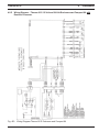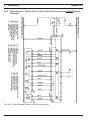
1
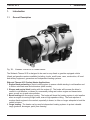
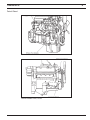
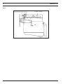
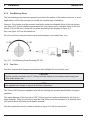
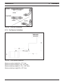
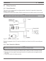
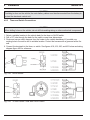
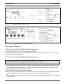
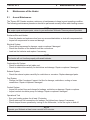
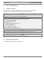
Thermo 90 S Installation / Operation Manual
Contents
Contents
1. Introduction
1.1 General Description ........................................................................................................ 101
1.2 Legal Provisions ............................................................................................................. 102
1.3 Meaning of Warning, Caution and Note.......................................................................... 102
2. Operating your Webasto Thermo 90 S
2.1 Switching On...................................................................................................................
2.2 Switching Off...................................................................................................................
2.3 Engine Preheating ..........................................................................................................
2.4 Engine and Sleeper Heating...........................................................................................
2.5 Operation with Digital Timer Models 1529 & 1531 .........................................................
2.6 Digital Timer Operating Instructions ...............................................................................
201
202
202
202
202
203
3. Technical Data
3.1 Technical Data................................................................................................................ 301
3.2 Enclosure Dimensions .................................................................................................... 302
3.3 Heater Dimensions ......................................................................................................... 303
4. Installation
4.1 General Information ........................................................................................................
4.2 Installation Locations ......................................................................................................
4.3 Mounting the Heater .......................................................................................................
4.4 Muffler and Exhaust Pipe Connection ............................................................................
4.5 Combustion Air Supply ...................................................................................................
4.6 Plumbing the System......................................................................................................
4.6.1 General Information .............................................................................................
4.6.2 Select Your Plumbing...........................................................................................
4.6.3 Sleeper and Engine Block Heating ......................................................................
4.6.4 Contents – Engine Connections...........................................................................
4.7 Fuel System....................................................................................................................
4.7.1 General Description .............................................................................................
4.7.2 Fuel Metering Pump.............................................................................................
4.7.3 Fuel Line ..............................................................................................................
4.7.4 Fuel System Limitations .......................................................................................
4.7.5 Fuel Stand Pipe....................................................................................................
4.7.6 Fuel Filter .............................................................................................................
4.8 Wiring Connections.........................................................................................................
4.8.1 General Information .............................................................................................
4.8.2 Power Connection to Batteries.............................................................................
4.8.3 Timer and Switch Connections ............................................................................
4.8.4 Sleeper Fan Wiring ..............................................................................................
4.8.5 Wiring Diagram- Thermo 90 S Enclosure and Compact Kit.................................
4.8.6 Wiring Diagram- Thermo 90 S German Version ..................................................
401
401
402
404
405
406
406
406
406
409
421
421
421
422
423
423
424
425
425
425
425
427
429
430
I
Contents
Thermo 90 S Installation / Operation Manual
Contents
4.9 Initial Operation............................................................................................................... 431
5. Maintenance of the Heater
5.1 Annual Maintenance ....................................................................................................... 501
6. Basic Troubleshooting
6.1 General Information ........................................................................................................
6.2 General Failure Symptoms .............................................................................................
6.3 Operational Failure Symptoms .......................................................................................
6.3.1 Operational Failure Symptoms (reading the flash code)......................................
6.4 Reading a Fault Code with 1531 “Comfort” Timer Installed ...........................................
6.4.1 Storing a Fault Code in Memory ..........................................................................
6.4.2 Reading and Removing Fault Codes Stored in Memory
using PC Diagnostics Kit P.N. 49440A ...............................................................
601
601
602
603
603
603
604
List of Figures
101
301
302
303
304
305
306
401
402
403
404
405
406
407
408
409
410
411
412
II
Thermo 90 S ...................................................................................................................
Enclosure Box Dimensions.............................................................................................
Enclosure Cover Dimensions .........................................................................................
Heater Dimensions .........................................................................................................
Control Unit Dimensions .................................................................................................
Fuel Pump Dimensions...................................................................................................
Muffler Dimensions .........................................................................................................
Installation Locations ......................................................................................................
Permissible Enclosure Box Mounting Positions..............................................................
Enclosure Box Mounting (Back Wall Shown) .................................................................
Perpendicular Mounting Brackets...................................................................................
Permissible Heater Installation (Compact and Basic Kits) .............................................
Muffler Mounting Detail...................................................................................................
Exhaust Discharge Positioning .......................................................................................
Parallel Plumbing Circuit.................................................................................................
Series Plumbing Circuit ..................................................................................................
Plumbing with Auxiliary Heat Exchanger ........................................................................
Engine Block Preheating and/or Boost Heating..............................................................
Typical Installation Parameters (Enclosure and Compact Kit) .......................................
101
302
302
303
304
304
304
401
401
402
402
403
404
405
406
407
407
408
421
Thermo 90 S Installation / Operation Manual
Contents
List of Figures
413
414
415
416
417
418
419
420
421
422
423
424
Fuel Metering Pump Mounting (DP 30) ..........................................................................
Fuel Line Connection......................................................................................................
Fuel System Limitations..................................................................................................
Fuel Stand Pipe ..............................................................................................................
Harness Connection Points ............................................................................................
On/Off Switch..................................................................................................................
72 Hour Quartz Timer with On/Off Switch ......................................................................
7 Day Digital Timer Model 1529 .....................................................................................
7 Day Digital Timer Model 1531 .....................................................................................
Sleeper Fan Wiring Using Interlock Harness P.N. 905.663 ...........................................
Wiring Diagram-Thermo 90 S Enclosure and Compact Kit ............................................
Wiring Diagram-Thermo 90 S German Version..............................................................
422
422
423
423
425
426
426
426
427
428
429
430
List of Tables
201
301
601
602
Digital Timer Instructions ................................................................................................
Technical Data................................................................................................................
General Failure Symptoms .............................................................................................
Operational Failure Symptoms .......................................................................................
203
301
601
602
First Edition Oct. 1997
P.N. 907505
III
Thermo 90 S
1.
Introduction
1.1
General Description
1
Introduction
Fig. 101: Webasto Thermo 90 S Coolant Heater
The Webasto Thermo 90 S is designed to be used on any diesel or gasoline equipped vehicle
(diesel and gasoline versions available) including: trucks, small buses, vans, construction, off-road
and military equipment, generators and independent heating systems.
Webasto Thermo 90 S Coolant Heater Applications:
1. Engine block preheating of liquid cooled engines to ensure reliable starting in cold weather and
to reduce cold start wear and emissions (white smoke).
2. Sleeper and engine block heating with the engine off. The heater will increase the driver’s
comfort in cold weather, cut down on unnecessary idling and reduce engine and transmission
wear, as well as, air and noise pollution.
3. Boost heating with the engine running. The heater will boost the heating system in cold weather
when an engine is running at light loads, even at high speeds or idling. The heat rejection of
modern diesel engines to the coolant, especially in buses, is often no longer adequate to heat the
vehicle’s interior.
4. Cargo heating - The heater can be used in independent heating systems to protect valuable
cargo (produce, beverages, paint) from freezing.
101
1
Introduction
Thermo 90 S
5. Marine - For use as an auxiliary or primary heat source for interior comfort or, as an engine
pre-heater.
Boat installations should only be performed by a Webasto authorized marine dealer.
It is the dealer’s responsibility that the installation complies with all applicable Coast Guard
regulations.
1.2
Legal provisions
Heater installation must be performed in accordance with the manufacturer`s installation
instructions.
Any deviation from these instructions are only permitted with the written approval from Webasto
Thermosystems Inc.
It is the dealer’s responsibility to approve installations not performed by Webasto trained
personnel.
Installation not complying with the installation instructions release Webasto Thermosystems Inc.
from any product liability.
OEM installations must be approved by Webasto Thermosystems Inc.
1.3
Meaning of Warning, Caution and Note
WARNING
This heading is used to highlight that non-compliance with instructions or procedures may cause
injuries or lethal accidents to personnel.
CAUTION
This heading is used to highlight that non-compliance with instructions or procedures may cause
damage to equipment.
NOTE
This heading is used to highlight and draw specific attention to information.
102
Thermo 90 S
2.
2
Operating the Webasto Thermo 90 S
Operating the Webasto Thermo 90 S
WARNING
Due to the risk of carbon monoxide poisoning and asphyxiation, the heater must not be operated in
enclosed spaces such as garages or workshops without adequate exhaust extraction.
WARNING
Do not operate any Webasto heater in an area where toxic or explosive materials or fumes may be
present. The heater must be switched “OFF” while refueling and at fueling stations.
NOTE
If heater is being switched on while the engine is at operating temperature, only the circulating
pump will run, coolant temperature must fall below 167°F. (75°C.) before heater will start.
NOTE
Restarting the heater during the after-run period is permitted.
Before switching on the Thermo 90 S, set vehicle heating system to the “heat” position and open any
shut off valves. Depending on the type of control installed in the dashboard of the vehicle, the
Thermo 90 S can be operated by the following methods.
2.1
Switching On
Using a timer:
Using a switch:
Timer
Switch
Pushing the “instant heat” button lights the “operation indicator” on the timer.
Or
When the switch is used for turning “ON” the Thermo 90 S, the operation indicator (toggle) lights up.
The coolant circulating pump, ceramic igniter and combustion air fan start operation and after
approximately 50 seconds combustion starts (audible combustion sound). After the coolant
temperature has reached the set point of 176°F (80°C) the Thermo 90 S will automatically adjust its
heat output to a lower operating range (variable heat output). If the temperature of the coolant
continues to rise and climb over 194°F (90°C) at the heater outlet it will cycle off. When the
temperature falls below 167°F (75°C) the heater will restart and repeat the cycle.
The Thermo 90 S will cycle on and off until:
201
2
1.
2.
3.
4.
5.
Operating the Webasto Thermo 90 S
Thermo 90 S
The Thermo 90 S is switched off.
Time has elapsed on the timer.
The vehicle battery voltage drops below 10.5V (20.5V).
The Thermo 90 S runs out of fuel.
A fault lock out occurs, indicated by a coded flashing signal on the operating indicator light during
the after run cycle of the heater or if equipped with a model 1531 7-Day Digital Comfort Timer a
fault code number (i.e. 07) will be displayed in the timer window until the fault is cleared.
(refer to Troubleshooting section of this manual for further information).
2.2
Switching Off
When heating is no longer required, switch the Thermo 90 S heater off. The indicator light turns off,
combustion extinguishes followed by an after run cycle of approximately 90 seconds.
2.3
Engine Preheating
1. Set the timer 30 min. to 1 hr. before you want to start engine. The heater will start up at set time.
(See timer operating instructions.)
Or switch the toggle switch or “instant on” switch on your timer in the vehicle dash to “ON”.
The heater will start up.
2. When the run time has elapsed on your timer the Thermo 90 S will automatically shut down.
Or, when engine preheat is no longer required, switch the Thermo 90 S heater “OFF”.
The Thermo 90 S will go through the after-run cycle.
2.4
Engine and Sleeper Heating
NOTE
To reduce battery discharge, turn off unnecessary equipment, i.e. radio, position lights, etc.
NOTE
Continuous fan operation over extended periods will run down the vehicles batteries.
1. Switch the toggle switch (or the “instant on” button of the timer) in the vehicle dash to “ON”.
The heater will start up if coolant temperature is below 167°F (75°C). Above this temperature only
the coolant circulation pump will run until coolant temperature drops below 167°F (75°C).
2. Switch on the thermostat and set to desired comfort range. The fan will cycle “ON” and “OFF” and
maintain selected comfort range.
3. When engine and sleeper heating is no longer required, switch the Thermo 90 S “OFF”.
The Thermo 90 S will go through the after-run cycle.
NOTE
Different blower interlock harnesses are available, check with your Webasto distributor/dealer for
options and application.
2.5
202
Operation with Digital Timer Models 1529 & 1531
Thermo 90 S
2
Operating the Webasto Thermo 90 S
Both timers enable you to preset the start time of the heater up to 7 days in advance.
It is possible to program 3 different starting times, of which only one can be activated at any one
time.
The model 1531 “Comfort” Timer features a wakeup alarm function and an error code display.
The Timer can be programmed in that all flashing symbols can be adjusted by means of the and
buttons. See table 201 below for setting reference or full instructions supplied with timer.
2.6
Digital Timer Operating Instructions
Note: For purposes of these instructions,1529 timer uses a
the 1531 timer uses a symbol button.
symbol button for programming where
Switching the heater on Manually: by pressing the button (continuous heating mode)
Automatically: by programming the heater starting time
Switching the heater off Manually: by pressing the button
Automatically: after the programmed operating time has elapsed.
With the heater running: by programming the remaining operating time.
Setting time / day of
the week
Press the button for more than 2 seconds - time of the day is flashing - and set the clock
using the and buttons. After 10 seconds, day of the week begins flashing - set the day
of the week in the same manner as the time.
Viewing the time
With the ignition switched off: press the
Programming heater
starting time
Press the button - the memory location is flashing - using the and buttons set start of
the heater operating time. After 10 seconds, day of the week begins flashing - set the day of
the week on which the heater is to turn on.
By repeatedly pressing the button, memory locations 2 and 3 can be programmed or the
time display mode can be reached.
Recalling / erasing
preset times
Repeatedly press the
preset time, press the
the memory location.
Programming duration
of operating time
The heater must be switched off. Press the button for 3 seconds - operating time is
flashing - and set the desired operating time (10 to 120 minutes) using the and buttons.
Setting the remaining
operating time
(Bus wiring Option)
Set the desired remaining operating time (1 to 120 minutes) using the and buttons. The
remaining operating time refers to the time the heater still continues to remain in operation
after the vehicle ignition is turned off. It can only be changed while the heater is in operation
and the ignition switched off.
Setting the wakeup
time
(Model 1531 Digital
Comfort Timer Only)
A wakeup time can only be programmed on the “1531” comfort digital timer. The wakeup
time is not bound to a specific day of the week. Repeatedly press the button until the bell
symbol appears on the display. Set the desired wakeup time using the and buttons.
The alarm clock turns off after 5 minutes or when one of the buttons is pressed.
Recalling / erasing the
wakeup time
To recall the wakeup time, repeatedly press the button until bell symbol appears on the
display - read off wakeup time. To erase the wakeup time: press the button until the bell
symbol is no longer visible on the display.
Remote control
Possible by means of an optional external signal.
button (bus wiring).
button until the desired memory location is displayed. To erase the
button several times until the time of the day is displayed instead of
Table 201: Digital Timer Instructions
203
Thermo 90 S
3.
Technical Data
3.1
Technical Data
3
Technical Data
The following data is subject to the normal tolerance for heaters, if no tolerance is specified.
This is approximately +/-10% in an ambient of 68°F (20°C) at nominal voltage.
Heater
Thermo 90 S Diesel (D)
Design
Coolant heater with evaporator burner (Ferro-Tech Technology)
Heat Output Btu/hr (kW)
Boost (Maximum 2 hours)
Variable Heat Output
From
To
Thermo 90 S Gasoline (B)
31,000 (9.1)
Not Applicable
6,100 (1.8)
26,000 (7.6)
6,800 (2.0)
26,000 (7.6)
Diesel #1 Diesel #2 and Arctic
Gasoline
0.28 (1.10)
Not Applicable
0.05 (0.19)
0.24 (0.90)
0.06 (0.25)
0.26 (1.00)
Rated Voltage
12 or 24
12 V only
Operating Voltage
10.5... 15 or 20.5... 30
10.5... 15
7.5 Amps or 90 Watts
Not Applicable
3.0 Amps or 37 Watts
6.9 Amps or 83 Watts
3.0 Amps or 37 Watts
6.9 Amps or 83 Watts
Fuel
Fuel Consumption gal/hr (l/hr)
Boost
Variable Heat Output
From
To
Power Consumption @ 12 Volts
Boost
Variable Heat Output
From
To
Operating Temperature Range of
Heater
Fuel Pump
– 40°... +230° F (– 40°... +110° C)
– 40°... +68° F (– 40°... +20° C)
Storage Temperature
– 40°... +130° F (– 40°... +54° C)
Min. Capacity of Coolant System
1.6 Gallons (6.0 Liters)
Permissible Operating Pressure
of Coolant System
6.0 ... 29 psi or 0.4 ... 2.0 bar
Flow Rate of Coolant Pump
7.25 gal/min. or 1650 l/hr against 0.15 bar pressure
CO in Exhaust Gas % by Vol.
10 ... 12 max.
CO in Exhaust Gas % by Vol.
0.1% max.
Bacharach Smoke Spot Number
<6
Dimensions of Heater
Length 14.0” (355 mm)
Width 05.24” (133 mm)
Height 08.66” (220 mm)
Dimensions of Enclosure
Length 15.75” (400 mm)
Width 07.50” (190 mm)
Height 14.0” (355 mm)
Weight incl. Enclosure
35.0 lb. (16 kg.)
Weight of Heater Incl. Control Unit
10.5 lb. (4.8 kg.)
Table 301: Technical Data
301
3
3.2
Technical Data
Enclosure Dimensions
Fig. 301:
302
Enclosure Box Dimensions
Thermo 90 S
Thermo 90 S
3
Technical Data
Fig. 302: Enclosure Cover Dimensions
3.3
Heater Dimensions
Fig. 303: Heater Dimensions
303
3
Technical Data
Fig. 304: Control Unit Dimensions
Fig. 305: Fuel Pump Dimensions
Fig. 306: Muffler Dimensions
304
Thermo 90 S
Thermo 90 S
4.
Installation
4.1
General Information
4
Installation
Webasto will take you step by step through the installation process to ensure successful operation
for years to come. The installation must be performed in accordance with the installation instructions
provided in this manual.
WARNING
The heater must not be installed in either the driver’s compartment or in the passenger area of
vehicles.
NOTE:
This manual does not cover all possible installations. For special applications use this manual as a
general guideline only. Contact an authorized Webasto dealer or Webasto Thermosystems directly
at USA: 1-800-555-4518 Canada: 1-800-667-8900
4.2
Installation Locations
Fig. 401: Installation Locations
1. Behind cab or sleeper.
2. On left/right side of the frame.
3. In an existing enclosure (tool box) on the vehicle.
The Thermo 90 S should be installed as low as possible in the cooling system to assure static
bleeding of the heater and the circulating pump.
NOTE
The circulating pump is not self priming.
401
4
Installation
Thermo 90 S
Fig. 402: Permissible Enclosure Box Mounting Positions
4.3
Mounting the Heater
A. Enclosure box frame rail mounting.
1. Remove the enclosure cover.
2. Pick 4 mounting holes in the back wall of enclosure, 2 on each side and mark frame rail.
Drill holes (Ø 1/2") on each side where marked.
3. With bolts supplied, fasten the enclosure box to frame frame rail.
Fig. 403:
Enclosure Box Mounting (Back Wall Shown)
CAUTION
Do not weld enclosure or angle brackets to the frame.
402
Thermo 90 S
4
Installation
Fig. 404: Perpendicular Mounting Brackets
NOTE
Brackets for perpendicular mounting are available. Order part # 905.822.
B. Enclosure box top frame bracket mounting (behind cab).
1. Drill and install top frame brackets with clamps provided (optional top frame mounting bracket
kit part no. 600.055).
2. Remove the enclosure cover.
3. Position enclosure box on brackets making adjustments where necessary to ensuring
adequate clearance for muffler and muffler attachment bracket.
4. Locate the 4 holes in base of enclosure and mark on mounting brackets.
5. Drill holes (Ø 1/2") on each bracket where marked.
6. With bolts supplied, fasten enclosure box to top frame brackets.
C. Basic and Compact heater kit mounting.
When ever the heater is installed in an existing enclosure box the installation template (provided with
heater kit) must be used and adequate ventilation [1 in² (6 cm²)] must be provided.
Heater must be protected from contaminates such as road splash, salt, mud and debris.
DO NOT mount heater inside passenger, sleeper or storage areas.
1. Ensure adequate clearance for heater and components in existing enclosure or mounting
area.
2. Lay out supplied mounting template and mark all holes for drilling keeping in mind location for
exhaust, coolant lines and wiring access. Once all requirements are met, drill holes.
3. Mount heater and components according to your plan, fasteners for mounting heater are
provided.
403
4
Installation
Thermo 90 S
Fig. 405: Permissible Heater Installation (Compact and Basic Kits)
4.4
Muffler and Exhaust Pipe Connection
WARNING
Exhaust pipes must be so routed that the possibility of exhaust fumes entering the vehicle is
unlikely.
CAUTION
Route the exhaust pipe in such a way as to prevent touching or being directed toward any part of
the vehicle that may be damaged by heat (i.e., brake lines, electrical wiring, hoses).
A. Enclosure and Compact Heater Kits.
1. Insert 2" (51mm) long coupler to heater exhaust port (no clamps required).
2. Insert end of muffler into coupler and fasten to bottom of enclosure box with supplied bracket
and bolts.
3. The discharge opening of the exhaust system must not point in the direction of travel, and so
located that any possible clogging caused by snow, mud or foreign materials are avoided.
404
Thermo 90 S
4
Installation
Fig. 406: Muffler Mounting Detail
B. General instructions for exhaust systems.
Modification to the exhaust system is permitted and must be done in accordance with the following
statements and instructions:
An optional exhaust pipe I.D. 1 1/2" (38 mm) can have a length up to 6.5’ (2 m) including muffler and
may have several bends (totaling 360°). It is mandatory to use the muffler. In installations where the
muffler is to be mounted other than on the enclosure box, it should be located as close to the heater
as possible.
Rigid exhaust pipe may be used, bends must be formed (smallest bending radius 3 3/8" (85 mm). Do
not weld pipe to make 90° corners. Any condensation water in the exhaust pipe must be discharged.
If necessary, drill a drain hole at the lowest point.
Route the exhaust system in such a way as to avoid touching or being directed towards any heat
sensitive materials or components (i.e., brake lines, electrical wiring, hoses).
Exhaust discharge must always be positioned straight down at point of exit plus or minus 10
degrees.
NOTE
Additional flexible exhaust tubing is available from your Webasto Distributor or Dealer under part
number 353 221.
C. Basic and Compact Heater Kits.
1. Mount muffler as close to heater as possible.
2. Run exhaust tubing from heater to muffler and from muffler to an appropriate discharge area.
3. Secure all exhaust connections with clamps provided.
4. Position exhaust discharge end of tubing straight down (see figure 407) and clamp securely
in place.
One meter (39 inches) of flexible exhaust tubing is supplied with Basic and Compact heater kits.
405
4
Installation
Thermo 90 S
Fig. 407: Exhaust Discharge Positioning
4.5
Combustion Air Supply
WARNING
Never draw combustion air from inside the vehicle, or from areas where fumes or gases can
accumulate. Drawing of combustion air from areas where people are present is strictly prohibited!
A combustion air intake tube I.D. 1.18" (30 mm) must be installed on the “Basic” and “Compact”
versions of the Thermo 90 S heater.
Combustion air intake tubing should be kept as short as possible and should not exceed 6.5’ (2m).
Bends in the combustion air tubing should not exceed 360° total. The smallest bending radius
allowed is 1.8" (45mm).
Combustion air should always be taken from a clean area, and should be routed in a gradual
downward slope away from heater allowing moisture to drain.
The intake opening of the combustion air tube must not point in the direction of travel to avoid any
possible clogging caused by snow, mud or foreign materials.
406
Thermo 90 S
4.6
Plumbing the System
4.6.1
General Information
4
Installation
The Thermo 90 S with coolant circulating pump must be mounted at least 6" (15 cm) below the
lowest permissible coolant level of the vehicles cooling system.
Minimum amount of coolant in the cooling system should be at least 1.6 gal. (6.0 l). Independent
heating systems require a minimum of 3.0 gal. (12.0 l). A minimum of 10% of a good quality
antifreeze should be maintained in the cooling system at all times.
Heater and water pump fit 3/4” (19 mm) I.D. heater hose meeting SAE 20 R3 specifications.
Silicone hose requires special hose clamps.
WARNING
When working on the coolant system, allow the engine to cool down and open the radiator cap
carefully.
NOTE
Heater hose must meet SAE 20 R3 specifications.
NOTE
Silicone hose requires special hose clamps.
NOTE
Hose clamps must be tightened to to 45 in/lb. (5 Nm) torque.
NOTE
Vehicles with a normally closed solenoid shut-off valve, require an additional relay and circuitry for
proper heater operation whenever vehicle is turned off.
4.6.2
Select your Plumbing
Instructions for options A - B - C - D
1. Remove radiator cap and release system pressure.
2. Close shut off valves for heating system, if equipped, or pinch off supply and return line with hose
clamping pliers or long nose vise-grip pliers.
3. Plumb the system depending on the vehicles particular set up as shown in plumbing options A, B, C
or D.
4. Remove hose clamping pliers and open shut off valves.
5. Top off engine coolant as per engine manufacturer’s recommendations and re-install the radiator
cap.
407
4
4.6.3
Installation
Thermo 90 S
Sleeper and Engine Block Heating
A: Parallel Plumbing Circuits
Fig. 408: Parallel Plumbing Circuit
Parallel plumbing circuits:
Vehicles equipped with heating/air conditioning units and normally closed solenoid coolant shut-off
valves require an additional relay and circuitry to overide the solenoid valve whenever the Webasto
heater is in operation.
This modification is necessary to ensure coolant circulation during Webasto heater operation.
408
Thermo 90 S
4
Installation
B: Series Plumbing Circuit
Fig. 409: Series Plumbing Circuit
C: Plumbing with Auxiliary Heat Exchanger Kit P.N. 905.670
NOTE
Recommended plumbing for Peterbilt, Navistar, Ford AeroMax and Volvo VN.
Fig. 410: Plumbing with Auxiliary Heat Exchanger
409
4
Installation
Thermo 90 S
Plumbing with auxiliary heat exchanger:
For vehicles with continuous fan operation or high amperage heat exchanger fans, Webasto
recommends the use of an auxiliary heat exchanger with low power consumption and a Webasto
room thermostat (P.N. 560.129).
Heat exchanger kit P.N. 905.670 provides everything necessary for this type of installation.
D: Engine Block Preheating and/or Boost Heating
Fig. 411: Engine Block Preheating and/or Boost Heating
Engine Block Preheating and/or Boost Heating:
1. Remove radiator cap and release system pressure.
2. Drain coolant from engine.
3. Plumb the Webasto system as shown above.
4. Refill engine coolant as per engine manufacturer’s recommendations and re-install the radiator
cap.
410
Thermo 90 S
5
4.6.4 Contents – Engine Connections
Caterpillar
3116 .............................................................................................................................
3176 .............................................................................................................................
3306 .............................................................................................................................
3406 .............................................................................................................................
3408 .............................................................................................................................
C-10/C-12 .......................................................................................................................
Cummins
B Series ..........................................................................................................................
C Series ..........................................................................................................................
KTA1150.........................................................................................................................
L10 .............................................................................................................................
M11 .............................................................................................................................
NT, BIG CAM II...............................................................................................................
NT, BIG CAM IV, N14.....................................................................................................
Detroit Diesel
Series 50.........................................................................................................................
Series 55.........................................................................................................................
Series 60.........................................................................................................................
6V92, 8V92 .....................................................................................................................
Mack
E6
.............................................................................................................................
411
411
412
412
413
413
414
415
415
416
416
417
417
418
418
419
419
420
411
Thermo 90 S
4
Caterpillar
Caterpillar 3116
Caterpillar 3176
413
Thermo 90 S
4
Caterpillar
Caterpillar 3306
Caterpillar 3406
414
Thermo 90 S
4
Caterpillar
Caterpillar 3408
Caterpillar C-10, C-12
415
Thermo 90 S
4
Cummins
Cummins B Series
416
Thermo 90 S
4
Cummins
Cummins C Series
Cummins KTA1150
417
Thermo 90 S
4
Cummins
Cummins L10
Cummins M11
418
Thermo 90 S
4
Cummins
Cummins NT, BIG CAM II
Cummins NT, Big Cam IV, N14
419
Thermo 90 S
4
Detroit Diesel
Detroit Diesel Series 50
Detroit Diesel Series 55
420
Thermo 90 S
4
Detroit Diesel
Detroit Diesel Series 60
Detroit Diesel 6V92, 8V92
421
Thermo 90 S
4
Mack
Mack E6
422
Thermo 90 S
4
4.
Installation
4.7
Fuel System
4.7.1
General Description
Installation
The metering pump, fuel line and fuel stand pipe are integral to the systems reliability and must be
installed according to these instructions to ensure proper heater operation.
CAUTION
If your installation exceeds the maximum allowable suction height or the fuel line as supplied is not
long enough, the fuel pump must be remotely mounted (see detailed instructions in sections 4.7.2
and 4.7.4)
CAUTION
If the fuel tank is higher than the fuel pump, the top of the tank may not be more than 20" above the
pump.
NOTE
Use supplied hose clamps to secure all fuel line connections.
Fig. 412: Typical Installation Parameters (Enclosure and Compact Kit)
Maximum suction height
Supplied fuel line length
(A) = 3’3" (1m)
(B) = 13’ (4m)
423
4
4.7.2
Installation
Thermo 90 S
Fuel Metering Pump
The fuel metering pump has been properly mounted to the bottom of the heater enclosure. In most
applications it will not be necessary to modify the manufacturer’s installation.
However, if the heater must be mounted outside the maximum allowable limits of the fuel system
(see figure 412, typical installation parameters) the fuel pump must be relocated closer to the fuel
source. If this is the case, mount the fuel pump according to the diagram in figure 413.
Also, see figure 415, fuel line limitations.
Do not mount fuel pump near heat sources (exhaust pipes, hot coolant lines, etc.)
Fig. 413: Fuel Metering Pump Mounting (DP 30)
4.7.3
Fuel Line
Fuel line, couplers and clamps are provided in the installation kit and must be used.
CAUTION
Fuel line must be secured every 12" (30cm) and kept away from hot exhaust and moving parts
(drive shaft, wheels, etc.
NOTE
Use supplied hose clamps to secure all fuel line connections.
The Thermo 90 S has been equipped with fuel line meeting the required specifications for proper
operation.
The inside diameter of this fuel line is 0.08" (2.0mm) and must not be substituted for fuel line of a
larger diameter. Doing so will result in improper fuel delivery and the formation of air pockets in the
fuel system which will interfere with heater operation.
Fuel line connections must be made as shown in figure 414, fuel line connection.
424
Thermo 90 S
4
Installation
Fig. 414: Fuel Line Connection
4.7.4
Fuel System Limitations
Fig. 415: Fuel System Limitations
Maximum suction height (A) = 3’3" (1m)
Maximum suction length (A + B) = 6’6" (2m)
Maximum delivery length (C + D) = 19’6" (6m)
Maximum delivery height (D) = 9’9" (3m)
425
4
4.7.5
Installation
Thermo 90 S
Fuel Stand Pipe
The fuel is drawn from the vehicles fuel tank through a fuel stand pipe. This stand pipe can be utilized on vehicles with a spare threaded port, or if no threaded port is available, a 1" hole can be
drilled into the tank and the universal tank boss installed as shown in figure 416. Keep the fuel stand
pipe 2" from the bottom of fuel tank.
Fig. 416: Fuel Stand Pipe
Fuel stand pipe installation:
1. Cut or extend fuel stand pipe to length, approx. 2" off fuel tank bottom. Remove burrs from cut
end.
2. Install the universal fuel stand pipe
- use 1/4" or 1/2" spare port on fuel tank (if available) and install fuel stand pipe
or
- drill 1" hole on top of tank (assemble tank-boss and fuel stand pipe) and install assembled
universal fuel stand pipe
3. Connect fuel line from fuel metering pump to fuel stand pipe using rubber connectors and clamps.
4. Route and secure fuel line from heater to fuel tank.
NOTE
Fuel stand pipe with universal tank boss can be installed from outside of tank. First assemble fuel
standpipe and tank-boss and simply work through 1” hole previously drilled into tank. Tighten
down with nut provided. Do not over-tighten.
4.7.6
Fuel Filter
The Thermo 90 S heater may be equipped with a fuel filter.
Fuel filters require changing at least annually and in cases of dirty fuel more often.
NOTE
If heater is equpped with a fuel filter, change filter at least annually
426
Thermo 90 S
4.8
Wiring Connections
4.8.1
General Information
4
Installation
The control unit is equipped with low voltage protection, therefore it is imperative to keep vehicle
batteries in good condition.
For sleeper and engine block heating, Webasto recommends a four battery system for best results.
NOTE
The Webasto heating system will not perform to your satisfaction with weak batteries.
Fig. 417: Harness Connection Points
Electrical components for the 12V version are labeled in red, those for the 24V version with green
labeling.
4.8.2
Power Connection to Batteries
NOTE
Clean battery terminals of corrosion before connecting the Webasto heater.
1. Route and secure wire harness from Webasto heater to battery box and cut harness to length.
2. Strip wires and crimp supplied ring tongue terminals to the positive (red) and negative (brown)
wire leads.
3. Connect the leads to the battery terminals.
427
4
Installation
Thermo 90 S
CAUTION
If welding is done on the vehicle, the main battery cables must be disconnected from the battery to
protect the electronic control unit.
4.8.3
Timer and Switch Connections
CAUTION
When drilling holes on the vehicle, do not drill into existing wiring or other mechanical components.
1. Select a suitable location in the vehicle dash for the timer or On/Off switch.
2. Drill a 1/2" hole through the dash for the switch or see timer dimensions.
3. Route and secure switch harness from the heater to the vehicle dashboard. If possible use
existing hole in fire wall or drill in suitable location. Protect the harness with a grommet at the fire
wall.
4. Connect the terminals to the timer, or switch. See figures 418, 419, 420, and 421 below and wiring
diagram figure 423 for reference.
Fig. 418: On/Off Switch
Fig. 419: 72 Hour Quartz Timer with On/Off Switch
428
Thermo 90 S
4
Installation
Fig. 420: 7 Day Digital Timer Model 1529
Fig. 421: 7-Day Digital Comfort Timer Model 1531
4.8.4
Sleeper Fan Wiring
A: Sleeper Fan is Cycled On/Off by Vehicle Thermostat
1. Turn ignition key to “ACC” position to power up sleeper.
2. Select desired temperature on thermostat and turn on sleeper fan to low position. Fan will cycle
On/Off to maintain temperature.
B: Sleeper Fan is Cycled On/Off by Webasto Thermostat
CAUTION
Leave waterproof connector uncoupled until completion of installation.
1. Install Webasto thermostat #129.560. Locate the thermostat in an area where routing of the wiring
is possible, about halfway between the ceiling and bed. Do not locate in direct air flow from the
heat exchanger nor mount to a cold surface.
2. Mount interlock relay near the heat exchanger.
3. Route one leg of the blower interface harness P.N. 905.663 from the relay to the Webasto heater
and the other leg to the thermostat and secure every 12 inches (30 centimeters).
4. Make wiring connections as shown in figure 422, sleeper fan wiring and figure 423, wiring diagram
- Thermo 90 S.
429
4
Installation
Thermo 90 S
C: Auxiliary Bunk Heat Exchanger Kit 905.670
Sleepers with continuous fan operation or high amperage heat exchanger fans.
1. Position the auxiliary heat exchanger in a suitable location under the bed, toolbox or other space
and secure as required.
2. Plumb coolant lines to the heat exchanger as shown in “C: Plumbing with Auxiliary Heat
Exchanger Kit P.N. 905.670” figure 410.
3. Make air duct connection at heat exchanger and route ducting into the sleeper.
4. Install Webasto thermostat #129.560. Locate the thermostat in an area where routing of the wiring
is possible, about halfwaybetween the ceiling and bed. Do not locate in direct air flow from the
heat exchanger or mount to a cold surface.
5. Mount interlock relay near the heat exchanger.
6. Route one leg of the included blower interface harness from the relay to the Webasto heater and
the other leg to the thermostat and secure every 12 inches (30 centimeters).
7. Make wiring connections as shown in figure 422, sleeper fan wiring and figure 423, wiring diagram
Thermo 90 S.
Fig. 422: Sleeper Fan Wiring Using Interlock Harness P.N. 905.663
430
Thermo 90 S
4.8.5
4
Installation
Wiring Diagram – Thermo 90 S 12 Volt and 24 Volt Enclosure and Compact Kit with
Deutsch Connector
Fig. 423: Wiring Diagram-Thermo 90 S Enclosure and Compact Kit
431
4
4.8.6
Installation
Wiring Diagram – Thermo 90 S 12 Volt and 24 Volt German Version without Deutsch
Connector
Fig. 424: Wiring Diagram-Thermo 90 S German Version
432
Thermo 90 S
Thermo 90 S
4.
Installation
4.9
Initial Operation
4
Installation
1. Check your installation for:
- loose nuts and bolts.
- exhaust system routing and clamp tightness.
- loose hose clamps.
- routing and securing of wiring and heater hoses.
- kinked or pinched hoses.
- routing and securing of fuel lines.
- battery connection and polarity.
2. Top off or refill cooling system with coolant as per engine manufacturers recommendations.
3. Open shut-off valves.
4. Set heater valve to max. heat position and turn off Air Conditioning in cab and sleeper.
5. Start the vehicle engine and run it at a fast idle for 10 minutes to purge air from the Thermo 90 S
and the heat exchanger. While the engine is running check:
- hose connections for leaks.
- coolant level in the expansion tank and add coolant as needed.
- Remove upper heater hose clamp and push screwdriver in between pipe and hose to let air
escape. Repeat this at least 4 times with engine running or use bleeder in the same manner
if so equipped.
6. Shut off the engine.
7. Re-connect hoses and tighten hose clamps used for bleeding system.
8. Connect power/switch extension harness to waterproof plug on side of heater enclosure
(Deutsch).
9. Switch on Webasto heater and check:
- green indicator light on.
- circulating pump in operation.
- initiation of start up sequence.
- successful start up and operation.
NOTE
Coolant temperature must be below 167°F (75°C) to start up.
433
4
Installation
Thermo 90 S
NOTE
Installation with long fuel lines may need a second start attempt to prime the fuel lines. Cycle
ON/OFF switch to reset control unit.
10. Temperature differential between water inlet and outlet should not exceed 10° C (18° F).
NOTE
The engine temperature gauge may read than actual heater output temperature. This is due to the
location of the temperature gauge sensor on the engine.
11. Vehicle equipped with sleeper heating option:
- turn vehicle ignition key to “ACC” position or switch Webasto thermostat “ON”.
- set thermostat in sleeper to highest heat position.
- the sleeper heat exchanger fan will blow warm air.
- turn thermostat down to lowest heat position and fan should cycle off.
12. Switch “OFF” Thermo 90 S heater and sleeper blower control.
13. Re-tighten hose clamps to 45 in/lb. (5 Nm) and inspect installation for leaks.
14. Complete the warranty card and send to Webasto Thermosystems.
NOTE
Necessary information to complete warranty card and ensure full warranty coverage can be found
on the heater name plate.
15. Install the stainless steel enclosure cover if equipped.
434
Thermo 90 S
5.
Maintenance of the Heater
5.1
Annual Maintenance
5
Maintenance of the Heater
The Thermo 90 S heater requires a minimum of maintenance to keep in good operating condition.
The following maintenance procedures should be performed annually before each heating season:
NOTE
For major repair and spare parts, return to your authorized Webasto Thermosystems Specialist.
Enclosure Box and Heater
- Clean the heater and enclosure box from any accumulated debris or dust with compressed air.
- Inspect all components for wear and damage.
Electrical System
- Check wiring harnesses for damage, repair or replace if damaged.
- Check the condition of the batteries and the connections.
- Load test the batteries and replace if necessary.
NOTE
The heater will not function properly with weak batteries.
Combustion Air System
- Check for obstructions at air intake port.
- Check air intake tube carefully for restrictions and damage. Repair or replace if damaged.
Exhaust System
- Check the exhaust system carefully for restrictions or corrosion. Replace damaged parts.
Fuel System
- Change fuel filter if equipped. Inspect fuel line for damage, restrictions, routing or loose
connections. Repair or replace if damaged.
Coolant System
- Inspect all coolant lines and clamps for leakage, restrictions or damage. Repair or replace.
- Inspect coolant circulation pump for leakage. Repair or replace if damaged.
Operational Test
- Run your heating system for at least 15 minutes.
- Check water and fuel connections for leakage. Re-tighten hose clamps if necessary.
- Check sleeper blower operation by turning on the thermostat, let the fan cycle on and off.
NOTE
Operate your Webasto at least once a month fo 20 minutes.
501
Thermo 90 S
5.
Basic Troubleshooting
5.1
General Information
6
Basic Troubleshooting
This section describes troubleshooting procedures for the Thermo 90 S coolant heater.
Troubleshooting is normally limited to the isolation of defective components.
CAUTION
Troubleshooting requires profound knowledge about structure and theory of operation of the heater
components and may only be performed by skilled personnel.
Before troubleshooting, check for and eliminate these defects:
- fuel supply (plugged fuel filter)
- corrosion on battery terminals
- blown fuses
- corrosion on electrical wiring and fuses
- corrosion on connectors
- loose contact on connectors
- wrong crimping on connectors
- shut down initiated by temperature limiter
NOTE
After any correction of a defect a functional test has to be performed in the vehicle.
NOTE
Coolant temperature must be below 167°F (75°C) to start up.
5.2
General Failure Symptoms
The following table lists possible failure symptoms.
601
6
Thermo 90 S
Basic Troubleshooting
Failure
Symptom
Probable Cause
Remedy
Coolant heater
switches off
automatically
(Fault lock-out)
No combustion after start
or automatic repeat start
Switch off heater momentarily and switch on once again
Flame extinguishes
during operation
Switch off heater momentarily and switch on once again
Heater overheats
Vehicle electrical system
voltage too low
Heater expels black
fumes from exhaust
Combustion air and/or
exhaust ducting blocked
Table 601:
5.3
Check coolant lines for obstructions, closed valves and kinks.
Check coolant level. Allow heater to cool down, reset over heat
limiter, switch off heater momentarily and switch on once again
Charge battery
Switch off heater momentarily and switch on once again
Check combustion and exhaust ducting for obstructions
General Failure Symptoms
Operational Failure Symptoms
Failure Symptom
Probable Cause
Check and Correct
No Function
-Electrical wiring, fuses
-Fuses
-Battery connections
-Positive on A5, negative on A3,
positive “ON” signal on A1
-Replace control unit
-Defective control unit
1X Flash (F 01)
No start no combustion after start
and repeat start
-Fuel system
-Combustion air
-Burner
2X Flashes (F 02)
Flame out during operation
-Fuel supply (shortage of fuel)
-Burner
3X Flashes (F 03)
Low voltage for more than
20 seconds
602
-Electrical system
-Fuel level
-Type of fuel being used
-Fuel filter
-Fuel line connections (air bubbles in
fuel lines)
-Air intake or exhaust, restricted or
plugged
-Clean burner pilot bores
-Restriction in the fuel system
-Fuel filter
-Fuel line connections (air bubbles in
fuel lines)
-Type of fuel being used
-Clean or replace burner
-Load test batteries
-Corrosion at connections
-Loose connections
Thermo 90 S
6
Basic Troubleshooting
4X Flashes (F 04)
Flame sensor permanently hot
-Defective flame sensor
-Replace flame sensor
5X Flashes (F 05)
Flame sensor
-Wiring
-Defective flame sensor
-Damaged wiring, open or short
circuit
-Replace flame sensor
6X Flashes (F 06)
Temperature sensor
-Wiring
-Defective temperature sensor
-Damaged wiring, open or short
circuit
-Replace temperature sensor
7X Flashes (F 07)
Fuel metering pump
-Wiring
-Defective fuel pump
-Damaged or corroded wiring, open
or short circuit
-Replace fuel pump
8X Flashes (F 08)
Combustion air fan
-Wiring
-Wrong RPM
-Defective combustion air fan
-Damaged wiring, open or short
circuit
-Replace combustion air fan
-Replace combustion air fan
9X Flashes (F 09)
Ceramic igniter
-Wiring
-Defective ceramic igniter
-Damaged wiring, open or short
circuit
-Replace ceramic igniter
10X Flashes (F 10)
Temperature limiter
-Overheat condition
-Coolant flow
CAUTION
-Wiring
-Defective temperature limiter
-Reset temperature
limiter
Troubleshooting
re-Coolant level quires
or flow restriction
profound knowl-Air trapped in coolant circuit
edge about structure
-Damaged or corroded wiring, open
or short circuitand theory of
operation
of the heater
-Replace temperature
limiter
-Damaged wiring, open or short
11X Flashes (F 11)
-Wiring
Table
602:
Operational
Failure Symptoms
circuit
Coolant circulating pump
-Defective coolant circulating pump
5.3.1 Operational Failure Symptoms (reading the flash code) -Replace coolant circulating pump
A flash code will be generated on the indicator light of the control
(on / off) switch in the event of an operational failure. In order to make a correct analysis it is necessary to understand the flash code event.
The flash code event is only visible during the after run (cool down)
period of operation.
During the flash code event you will see the following:
Five quick flashes followed by a slower sequence of flashes, the slower sequence of flashes is the
actual fault code. The first five quick flashes are only an indication that a fault
NOTE
code has been registered and will be displayed. Count only the slower seAfter
any
correction of
quence of flashes to
a defect a functional
obtain the current fault code.
test has to be perFor example (flashes = ¤):
Fault code 7X (F 07): ¤¤¤¤¤ ... ¤ ... ¤ ... ¤ ... ¤ ... ¤ ... ¤ ... ¤
The flash code sequence will be repeated until the Thermo 90 S
completes the after run (cool down) period after which, the fault code will be stored in memory.
603
6
5.4
Basic Troubleshooting
Reading a Fault Code with 1531 “Comfort” Timer
Installed
Thermo 90 S
CAUTION
Troubleshooting requires profound knowledge about structure
and theory of
operation of the heater
Where the Thermo 90 S installation includes the model 1531 “Comfort”
Digital Timer, you will be able to read the current failure fault code
directly from the timer display.
For example: fault code “07" (fuel pump) will be visible on the timer display.
Once the failure has been corrected, and the heater successfully starts and
runs, the error code will no longer be visible on the timer
CAUTION
display.
Diagnostics equipment
is intended for use by
5.4.1 Storing a Fault Code in Memory
Webasto trained personnel at authorized
Once the Thermo 90 S completes the after run (cool down) period
Webasto
initiated by a failure event, the current flash code will be downloaded
(stored) in memory.
The Thermo 90 S can store up to four fault codes.
NOTE
Once the memory is “full”, any additional fault code will replace the
After any correction of
earliest code stored thereby continually updating the fault codes
a defect a functional
stored in memory with the four most recent faults.
test has to be per5.4.2
Reading and Removing Fault Codes Stored in Memory
using PC Diagnostics Kit P.N.9009064C
It is possible to read and remove (reset) stored fault codes from the Thermo 90 S memory.
This is achieved through the use of a diagnostic interface kit
connected to the Thermo 90 S and an IBM compatible computer
having the necessary software installed.
The PC Diagnostic Interface Kit comes complete with instructions,
software and several interface connectors for use with Webasto
heaters equipped with internal diagnostics capabilities such as the
Thermo 90 S. (Order PC Diagnostics Kit under part number 9009064C)
Kit does not include required computer.
In addition to working with stored fault codes, the PC Diagnostics Kit allows you to do several other
functions such as reading values while the heater is in operation or testing individual components.
Printing out of fault codes is also available (User supplied printer required).
For further capabilities and instructions for use with the Thermo 90 S heater, see instruction manual
supplied with the PC Diagnostics Kit.
604