1
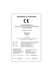
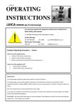
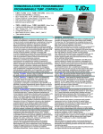
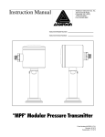
INDICATORE DA PANNELLO PROG. 2/4 AL.
PROGRAMMABLE PANEL METER 2/4 AL.
•
•
•
•
•
40.000 PUNTI DM500 , 120.000 PUNTI DM5000.
5 CIFRE ALTE 13,5mm / 1 CIFRA ALTA 10mm / 8 LEDS / 3 TASTI.
DIMENSIONI FRONTALI 48 X 96(orizz.) x 100(prof.) mm.
COMPLETAMENTE CONFIGURABILE A TASTIERA.
2 USCITE ALLARME A RELÈ / 4 USCITE ALLARME LOGICHE
♦
♦
♦
♦
♦
40,000 COUNTS DM500 , 120,000 COUNTS DM5000
5 DIGITS 13,5mm HEIGHT+1 DIGIT 10mm HEIGHT+8 LEDS+3 KEYS.
FRONTAL DIMENSIONS: 1/8 DIN (48 X 96horiz. x 100mm depth).
PUSH-BUTTON SET-UP.
2 ALARM RELAY OUTPUTS / 4 ALARM LOGIC OUPUTS.
DM500x
GENERALITA’
GENERAL DETAILS
Il DM500x è un indicatore/intercettatore digitale programmabile da
pannello totalmente configurabile da tastiera. E' possibile selezionare
il tipo di ingresso (tensione, corrente, termocoppia, termoresistenza,
ecc.), la scala, le corrispondenze di visualizzazione, gli allarmi, ecc...
La tastiera ridotta a soli tre tasti e l’ausilio di messaggi alfanumerici
facilitano l’operatore nella fase di programmazione.
La dimensione frontale è di soli 48x96mm ma il display è ben visibile
a distanza grazie ad un apposito filtro ottico ed a cifre alte 13,5mm
per il display principale (orange alta efficienza) e 10mm per il display
secondario (verde alta efficienza). La profondità è di soli 100mm.
Oltre a svolgere compiti di misura e visualizzazione risponde ad
esigenze di intercettazione grazie a 4 Set-Point di allarme con relative
uscite open collector (2 Set-Point di allarme nel caso di uscite a relè).
Permette inoltre la ritrasmissione della misura con uscita analogica
(es. 4÷20mA) oppure con uscita digitale mediante RS232 o RS485.
La sicurezza dei dati impostati ed acquisiti è salvaguardata mediante
chiave a tre livelli.
Sviluppato per rispondere a situazioni di vario tipo in sistemi di
regolazione e controllo è in grado di soddisfare le più disparate
esigenze sia per la completezza delle funzioni offerte , sia per
l’elevato numero di configurazioni disponibili.
Montaggio SMT, utilizzo di potente microcontrollore, flessibilità d’uso
e programmazione facilitata sono ulteriori elementi caratterizzanti.
The DM500x is a programmable digital panel meter which can be
programmed by using the push-buttons. It’s possible to select the
type of input (voltage, current, thermocouple, thermoresistance, etc.),
the ranges, the relationship between input variable and displayed
value, the alarms, etc...
Programming is simple thanks to the keyboard with only three pushbutton and alphanumeric helping messages.
The frontal dimensions are only 48x96mm but the display is visible
from far thanks to the optical filter and the size of the digits, 13,5mm
for the main display (high efficiency orange) and 10mm for the
secondary display (high efficiency green).The depth is 100mm only.
In addition to measuring and displaying functions, these instruments
are also able to support up to 4 (four) alarm Set-points with respective
open collector output(2 alarm Set-Points if relay output is requested).
They also allow the retransmission of measure with analog
(i.e. 4÷20mA) or digital output by RS232 or RS485.
There is a three levels’ key that protects the safety of setting
parameters and acquired data.
It was developed to satisfy the various requirement of regulation and
control systems, thanks to the completeness of the offered function
and the high number of available configurations.
SMT mounting, powerful microcontroller used, flexibility of use, easy
programming are further characteristics.
CARATTERISTICHE PRINCIPALI -CONFIGURAZIONI
MAIN CHARACTERISTICS - CONFIGURATIONS
CONFIGURAZIONE SCALE E INGRESSI
Sono previste molte possibilità , evidenziate nella tabella seguente :
RANGES AND INPUTS CONFIGURATION
Many possibilities are foreseen as shown in the following table:
CODE
IN
*
S.I.
UNIT
RANGE
min. IN. MAX IN.
DM500
min. dis. MAX dis.
DM5000
min. dis. MAX dis.
50 dc
mV
00,00
+50,00
-19999
20000
-19999
99999
1 dc
10 dc
V
V
-1,000
-10,00
+1,000
+10,00
-19999
-19999
20000
20000
-19999
-19999
99999
99999
20 dc
mA
-20,00
+20,00
-19999
20000
-19999
99999
5 dc *
A
-5,000
+5,000
-19999
20000
-19999
99999
CODE
IN
INPUT
SENSOR
min. k
MAX k
min. °C
MAX °C
RANGE
min. °F
MAX °F
Pt100
Pt 100
-199
500
Pt 100
-199,9
400,0
Pt100•
tc J
Tc J
0
900
Tc J
0
400,0
tc J•
tc k
Tc K
0
1.300
Tc K
0
400,0
tc k•
tc L
Tc L
0
900
Tc L
0
400,0
tc L•
tc n
Tc N
0
1.300
Tc N
0
400,0
tc n•
tc t
Tc T
0
400
Tc T
0
400,0
tc t•
tc r
Tc R
0
1.760
tc S
Tc S
0
1.760
tc b
Tc B
0
1.810
Nota: ogni sonda è linearizzata per ottenere una precisione teorica
migliore di 0,01°C per le termoresistenze e 0,1 °C per le termocoppie.
-328
932
74
773
-199,9
752,0
73,3
673,2
32
1652
273
1173
32,0
752,0
273,2
673,2
32
2372
273
1573
32,0
752,0
273,2
673,2
32
1652
273
1173
32,0
752,0
273,2
673,2
32
2372
273
1573
32,0
752,0
273,2
673,2
32
752
273
673
32,0
752,0
273,2
673,2
32
3200
273
2033
32
3200
273
2033
32
3290
273
2083
Note: each probe is linearised to obtain a theoretical precision better
than 0,01°C for RTDs and 0,1°C for thermocouples.
* Solo su richiesta ed esclude altri ingressi.
* Only on request and excludes other inputs.
Thermosystems s.r.l. , ITALY
DM 500x
Configurare l’ingresso significa predisporre lo strumento per il tipo di
segnale di ingresso e per le relative corrispondenze.
Nel gruppo “InPUt” troviamo le seguenti funzioni.
‘SEnSr’ Definisce l’ingresso vero e proprio.
‘InPLo’ Corrisponde al minimo della variabile di ingresso.
‘dISLo’ Corrisponde al minimo della visualizzazione.
‘InPHi’
Corrisponde al massimo della variabile di ingresso.
‘dISHi’
Corrisponde al massimo della visualizzazione.
Gli ingressi accettati possono essere di varia natura quali:
- tensione continua
- corrente continua
- temperatura a termoresistenza
- temperatura a termocoppia,
- resistenza
- potenziometro
- strain gauge
- ecc.
(gruppo “dISPL”)
CONFIGURAZIONE DISPLAYS
Permette di ottenere il formato di visualizzazione desiderato.
‘ OvEr’ La funzione ‘ OvEr’ corrisponde ad un limite logico max.
‘UndEr’ La funzione ‘UndEr’ corrisponde ad un limite logico min.
‘OFSEt’ Possibilità di correggere la misura.
‘dECIM’ Impostazione della posizione del punto decimale.
‘rOUnd’ Definisce l’arrotondamento della cifra meno significativa.
‘Unit’
Display dedicato all’indicazione dell’unità di misura.
Sono disponibili : ‘k’ , ‘°C’ , ‘°F’ , ‘U’ , ‘A’ , ‘g’ , ‘ ‘ .
(gruppo “AdCnv”)
CONFIGURAZIONE A/D CONVERTER
Configurare l’ A/D converter significa determinare il numero di
conversioni per unità di tempo, media e filtro.
‘t Cnv’
Il tempo di conversione = cadenza di lettura dell’ingresso.
‘n Avg’ Numero di letture per calcolare la media algebrica.
‘SCOSt’ Finestra simmetrica con compiti di filtro attivo.
CONFIGURAZIONE CHIAVE (SICUREZZA PARAMETRI)
Grazie alla chiave è possibile limitare l’accesso alla programmazione
delle funzioni così da evitare situazioni di manomissione o di
impropria impostazione da parte di personale non autorizzato.
Nel gruppo “kEyLk” troviamo la funzione:
‘LEvEL’ Tre diversi livelli che permettono tre diversi gradi di libertà:
OFF ---> corrisponde al minimo di sicurezza.
Lo ---> corrisponde ad un medio livello di sicurezza.
Hi ---> corrisponde al massimo livello di sicurezza.
(gruppo “rEtrS”)
CONFIGURAZIONE USCITA ANALOGICA
Vengono rese disponibili le funzioni che riguardano l’uscita analogica.
‘SPEEd’ Velocità di risposta dell’uscita rispetto all’ingresso.
Sono previste due possibilità:
Lo ---> 8.000 punti (tempo di ciclo pari a 20 ms).
Hi ---> 2.400 punti (tempo di ciclo pari a 6 ms).
‘An Lo’ Visualizzazione corrispondente al minimo dell’uscita anal.
‘OutLo’ Corrisponde al minimo dell’uscita analogica.
‘An Hi’
Visualizzazione corrispondente al massimo dell’uscita anal.
‘OutHi’ Corrisponde al massimo dell’uscita analogica.
CONFIGURAZIONE COMUNICAZIONE SERIALE (gruppo “rSCOM”)
Funzioni che riguardano l’interfaccia seriale per RS-232 o RS-485.
‘PrOtC’ Permette la scelta del protocollo di comunicazione.
Al momento sono possibili (altre possibilità in futuro):
OFF --->
comunicazione disabilitata.
thErM ---> protocollo di comunicazione Thermosystems.
‘ Addr’
Indirizzo assegnato allo strumento, compreso tra 1 e 255.
‘ bAUd’ Impostare il Baud rate scegliendo fra le seguenti possibilità:
300 , 600 , 1200 , 2400 , 4800 , 9600 .
‘ ModE’ definisce la precedenza operativa secondo due possibilità:
‘LOCAL’ ---> tastiera è totalmente operativa,
PC remoto solo per lettura dati e funzioni.
‘rEMOt’ ---> PC è totalmente operativo,
tastiera solo per lettura dati e funzioni.
CONFIGURAZIONE ALLARME 1 (Ch1)
Nel gruppo “ALrM1” sono disponibili i parametri con l’ordine seguente:
‘SOUrC’ Permette di definire qual’è l’ingresso del canale di allarme.
OFF --->
il canale di allarme è disabilitato (spento).
InPut ---> intercetta la variabile d’ingresso non filtrata.
FiLtr --->
intercetta la variabile d’ingresso filtrata.
‘ tyPE’
Allarme di massima oppure allarme di minima.
ALrHi ---> allarme di massima (superamento del Set).
ALrLo ---> allarme di minima (inferiore al Set).
‘Inhib’
Inibizione dell’allarme allo start (accensione).
OFF --->
funzione disabilitata.
On --->
funzione abilitata.
‘FUnCt’ Effettua o meno la negazione del livello logico d’allarme.
PoS --->
il livello logico dell’allarme resta invariato.
nEg --->
il livello logico dell’allarme viene invertito.
‘ rELE’ Effettua o meno l’inversione dello stato dell’uscita.
dir --->
lo stato dell’uscita resta invariato.
rEv --->
lo stato dell’uscita viene invertito.
‘rESEt’ Comportamento dell’uscita al cessare dell’allarme.
AUtOM ---> cambia stato al cessare dell’allarme
MAnUA ---> non cambia stato al cessare dell’allarme fino
all’intervento manuale dell’operatore.
DM500CII.DOC
Soggetto a modifiche senza preavviso.
CATALOG
To configure the input means to prearrange the instrument to the kind
of input signal and their correspondence.
In “InPUt” group we find these functions.
‘SEnSr’ To select the input.
‘InPLo’ It’s the minimum value of input.
‘dISLo’ It’s the minimum displayed value.
‘InPHi’
It’s the maximum value of input.
‘dISHi’
It’s the maximum displayed value.
There are many inputs like:
- d.c. voltage
- d.c. current
- thermoresistance
- thermocouple
- resistance
- potentiometer
- strain gauge
- etc.
(“dISPL” group)
DISPLAYS CONFIGURATION
It allows to get the required display format.
‘ OvEr’ The ‘ OvEr’ function corresponds to a max logic limit.
‘UndEr’ The ‘UndEr’ function corresponds to a min logic limit.
‘OFSEt’ It allows to correct the measure.
‘dECIM’ Decimal point position set.
‘rOUnd’ It fixes the round off of the less significative digit.
‘Unit’
Display unit selection.
There are available : ‘k’ , ‘°C’ , ‘°F’ , ‘U’ , ‘A’ , ‘g’ , ‘ ‘ .
(“AdCnv” group)
A/D CONVERTER CONFIGURATION
To configure the A/D converter means to calculate the number of
conversion for time unit, average e filter.
‘t Cnv’ Conversion time = variable input reading timing.
‘n Avg’ Number of reading to calculate weighted average.
‘SCOSt’ Symmetric window with active filter assignment.
KEY CONFIGURATION(SECURE PARAMETERS)
Thanks to the key lock it’s possible to restrict the access to the
function programmation to avoid tampering or wrong setting by
unauthorized personnel.
In “kEyLk” group we find the function:
‘LEvEL’ Three different levels with different degrees of freedom.
OFF ---> minimum security level.
Lo ---> medium security level.
Hi ---> maximum security level.
(“rEtrS” group)
ANALOG OUTPUT CONFIGURATION
It contains the functions related to the analog output.
‘SPEEd’ Output value set time compared to the input.
Two possibilities are available:
Lo ---> 8.000 counts (cycle time of 20ms).
Hi ---> 2.400 counts (cycle time of 6ms).
‘An Lo’ Displayed value corresponding to min value of analog out.
‘OutLo’ Minimum value of analog output.
‘An Hi’
Displayed value corresponding to max value of analog out.
‘OutHi’ Maximum value of analog output.
(“rSCOM” group)
SERIAL COMMUNICATION CONFIGURATION
Functions concerning serial interface for RS-232 or RS-485.
‘PrOtC’ It allows to choose the communication protocol.
There are available (other choices in future):
OFF --->
communication not available.
thErM ---> Thermosystems communication protocol.
‘ Addr’
Address assigned to the instrument, from 1 to 255.
‘ bAUd’ Choose Baud rate value:
300 , 600 , 1200 , 2400 , 4800 , 9600 .
‘ ModE’ It offers two possibility of operative priority:
‘LOCAL’ ---> keyboard is totally operative,
remote PC only for funct. and data reading.
‘rEMOt’ ---> PC is totally operative,
keyboard only for functions and data reading.
ALARM 1 (Ch1) CONFIGURATION
In “ALrM1” group the parameters are available in this order:
‘SOUrC’ It allows to define the input of alarm channel.
OFF --->
Alarm channel OFF.
InPut ---> get the not filtered input variable.
FiLtr --->
get the filtered input variable.
‘ tyPE’
Maximum or minimum alarm type.
ALrHi ---> Maximum alarm type(over Set).
ALrLo ---> Minimum alarm type(under Set).
‘Inhib’
Inhibition of alarm at start up.
OFF --->
function OFF.
On --->
function ON.
‘FUnCt’ It is possible to change the sign of the logic level of alarm.
PoS --->
Logic level of alarm not changed.
nEg --->
Logic level of alarm inverted.
‘ rELE’
It is possible to invert the output state.
dir --->
Output state not changed.
rEv --->
Output state inverted.
‘rESEt’ Determines the output state when alarm stops.
AUtOM ---> change state when alarm stops.
MAnUA ---> do not change state when alarm stops until
manual intervention by user.
pagina 2
Subject to change without notice.
data di stesura : 10/03/98
data di revisione : 19/03/01
Thermosystems s.r.l. , ITALY
DM 500x
‘rEFEr’ Relazione del canale di allarme interessato con la variabile
di misura e gli altri allarmi.
AbSLt ---> l’allarme del canale interessato è assoluto.
ALr 1 ---> l’allarme è relativo al Set-Point del canale 1.
ALr 2 ---> l’allarme è relativo al Set-Point del canale 2.
ALr 3 ---> l’allarme è relativo al Set-Point del canale 3.
ALr 4 ---> l’allarme è relativo al Set-Point del canale 4.
‘OndLy’ Corrisponde al ritardo di tempo tra la rilevazione della
situazione di allarme e la reale attivazione dell’uscita.
‘OFdLy’ Corrisponde al ritardo di tempo tra la cessazione della
situazione d’allarme e la reale disattivazione dell’uscita.
‘ SEt’
E’ il set point del canale di allarme interessato e vi si deve
immettere l’informazione numerica desiderata.
‘Hy Hi’
Corrisponde all’isteresi superiore, rispetto al Set Point.
‘Hy Lo’ Corrisponde all’isteresi inferiore, rispetto al Set Point.
‘SEtHi’ Rappresenta il limite superiore ammesso per il Set Point.
‘SEtLo’ Rappresenta il limite inferiore ammesso per il Set Point.
CONFIGURAZIONE ALLARME 2 (Ch2)
Vale tutto quanto riportato per “CONFIGURAZIONE ALLARME 1
(Ch1)” con l’accortezza di riferire tutto al canale 2.
CONFIGURAZIONE ALLARME 3 (Ch3)
Vale tutto quanto riportato per “CONFIGURAZIONE ALLARME 1
(Ch1)” con l’accortezza di riferire tutto al canale 3.
N.B.:ALLARME 3 è disponibile solo per versione con uscite logiche.
CONFIGURAZIONE ALLARME 4 (Ch4)
Vale tutto quanto riportato per “CONFIGURAZIONE ALLARME 1
(Ch1)” con l’accortezza di riferire tutto al canale 4.
N.B.:ALLARME 4 è disponibile solo per versione con uscite logiche.
DEFAULT:
E’ prevista la possibilità di caricare rapidamente i parametri di default
preimpostati in fabbrica mediante una sequenza temporale di tasti.
ERRORI:
E’ prevista la gestione/segnalazione degli errori sia di funzionamento
relativo all’indicatore/intercettatore, sia applicativi/funzionali.
Tale gestione comporta la segnalazione a mezzo display del codice di
errore incontrato e corrispondenti informazioni sono riportate sul
manuale di programmazione.
FUNZIONI DI IMMINENTE REALIZZAZIONE:
- Hold / Latch / Memory / Reset
- Peak / Valley
- Remote Set-Point
- Sistema dedicato a pesature
CATALOG
Relationship among operating alarm channel, measured
variable and other alarms.
AbSLt ---> Operating alarm channel is absolute.
ALr 1 ---> alarm relative to channel 1 Set-Point.
ALr 2 ---> alarm relative to channel 2 Set-Point.
ALr 3 ---> alarm relative to channel 3 Set-Point.
ALr 4 ---> alarm relative to channel 4 Set-Point.
‘OndLy’ Delay time between recognised alarm situation and actual
output activation.
‘OFdLy’ Delay time between stopping alarm situation and actual
output disactivation.
‘ SEt’
Operating alarm channel set point;let in your required
value.
‘Hy Hi’
Superior hysteresis, relative to Set point.
‘Hy Lo’ Inferior hysteresis, relative to Set point.
‘SEtHi’ Set Point maximum value.
‘SEtLo’ Set Point minimum value.
ALARM 2 (Ch2) CONFIGURATION
As above for “ALARM 1 (Ch1) CONFIGURATION”; remember to refer
all parameters to channel 2.
ALARM 3 (Ch3) CONFIGURATION
As above for “ALARM 1 (Ch1) CONFIGURATION”; remember to refer
all parameters to channel 3.
CAUTION: ALARM 3 is available only with logic output version.
ALARM 4 (Ch4) CONFIGURATION
As above for “ALARM 1 (Ch1) CONFIGURATION”; remember to refer
all parameters to channel 4.
CAUTION: ALARM 4 is available only with logic output version.
DEFAULT:
It’s possible to load quickly the factory preset values by using the
keyboard.
ERRORS:
The instrument allows handling and signaling of errors both for
controller functioning errors and for applicative/functional errors.
The display shows the error code found, information on which will be
found in the programming manual.
‘rEFEr’
NEXT TIME FUNCTIONS:
- Hold / Latch / Memory / Reset
- Remote Set-Point
CONNESSIONI ELETTRICHE
ELECTRICAL CONNECTIONS
ESEMPI APPLICATIVI
1312 1110 9 8 7 6
- Peak / Valley
- Weighing systems
APPLICATION EXAMPLES
1312 1110 9 8 7 6
1312 1110 9 8 7 6
1312 1110 9 8 7 6
NOTE: ONLY
FOR SPECIAL
ORDER
1312 1110 9 8 7 6
1312 1110 9 8 7 6
1312 1110 9 8 7 6
1312 1110 9 8 7 6
4 3 2 1
AUX. VOLTAGE
24Vdc <25 mA
32 1
RL2
RL1
AUX. VOLTAGE
AUX. VOLTAGE
RL1
24Vdc <50mA
24Vdc <50mA
1312 1110 9 8 7 6 5 4 3 2 1
RL2
4 3 2 1
1312 1110 9 8 7 6 5 4 3 2 1
+ - - - *
*
*
*
*=SSR
1312 1110 9 8 7 6 5 4 3 2 1
- - - +
-
*
-
*
*
* *=SSR
+
-
+
file: 500_SCH1
DM500CII.DOC
Soggetto a modifiche senza preavviso.
pagina 3
Subject to change without notice.
data di stesura : 10/03/98
data di revisione : 19/03/01
Thermosystems s.r.l. , ITALY
DM 500x
DIMENSIONI D’INGOMBRO - SPACCO PANNELLO
CATALOG
DIMENSIONAL DETAILS - PANEL CUT-OUT
CARATTERISTICHE TECNICHE
TECHNICAL DATA
FRONT
Lexan with high physical-chemical performance supported by
fiberglass-reinforced plastic.
KEYBOARD
3 push button 170g (ENTER, UP,DOWN/LEFT)
SIGNALING
DISPLAY : 5 orange high efficiency height 13,5 mm.
: 1 green high efficiency height 10 mm.
red LED high efficiency for:
- 1 2 3 4 : Alarm channel output.
- PK
: Peak.
-H
: Hold.
-L
: Local.
- LK
: Lock
INPUT
- VOLTAGE MEASURES
Ranges and scales:
0÷±50mVdc ; 0÷±1Vdc ; 0÷±10Vdc
(see general table)
±0,5 %
Accuracy:
Temperature drift:
< 500 ppm/°C on vfs.
Input impedence:
>1 MΩ
Set-up time:
< 1 sec (10÷90 %)
- CURRENT MEASURES
Ranges and scales:
0÷20mAdc ; (0÷5Adc on
request)
(see general table)
±0,5 %
Accuracy:
Temperature drift:
< 450 ppm/°C on vfs.
Input resistance:
< 2,7 Ω (input 0÷20mA)
< 0,01Ω (input 0÷5A )
Set-up time:
< 1 sec (10÷90 %)
- TEMPERATURE MEASURES
THERMOCOUPLE INPUT
Thermocouple L
according to DIN 43710
Thermocouples J - K - N - T - R - S – B according to IEC 584
automatic reference junction compensation (line 100Ωmax).
Range and scales:
(see general table)
Accuracy:
(see general table)
Temperature drift:
< 500 ppm/°C on vfs.
Error reference junct. comp.: < 0,1 °C/°C.
Set-up time:
< 1,3 sec (10÷90 %)
THERMORESISTANCE INPUT
RTD Pt100 according to DIN 43760
3 wires connection for RTD (line 10Ω max).
Ranges and scales:
(see general table)
Accuracy:
(see general table)
Temperature drift:
< 500 ppm/°C on vfs.
Max. current probe:
< 200µA
Set-up time:
< 1,5 sec (10÷90 %)
A/D CONVERTER
Dual ramp optimized integrator converter.
(max resolution 60.000 points x DM500, 200.000 points x DM5000).
Acquirement time:
0,5 ÷ 20sec (setting with steps to 0,1 sec).
Digital filter:
weighted average (from 1 to 50 reading).
ALARM OUTPUTS
- RELAY
relay SPST 3A @ 250Vac max; 30Vac/dc min (resistive load)
- LOGIC
24Vdc ±20% Ri=560Ω
AUXILIARY OUTPUT
- RETRANSMITTED ANALOG OUTPUT
continuous output 0÷20mA or 4÷20mA [Rmax 500Ω] or
continuous output 0÷1V or 0÷5V or 0÷10V [Rmin 500Ω].
±0,5 %
Accuracy:
Insulation:
500Vrms min.
- SERIAL OUTPUT
RS232 V.24
Multidrop linking with double port.
Address units:
80 max.
Length between two points: 20 m max.
Insulation:
200Vrms min.
RS485
Bus linking with two wires (termination 120Ω)
Address units:
24 max.
Length between two points: 1.000 m max.
Insulation:
200Vrms min.
AUXILIARY VOLTAGES
Iout MAX 25mA (DM500x out R)
24Vdc ±10%
Iout MAX 50mA (DM500x out S)
Insulation:
500Vrms min.
SUPPLY
100÷240Vac -15%/+10% or 15÷35Vac/dc -15%/+10%
Frequency:
50 - 60 Hz.
Power:
4 Watt max.
GENERAL CHARACTERISTIC
ENVIRONMENTAL:Op. temp. : 0 - 50°C
R.H.%:18 - 85% n.c.
SECURITY:
EN61010 - install cat. III –pollution degree 2.
ELECTROMAGNETIC COMPATIBILITY:
Standard EN 50081-1 (emission) and EN 50082-1 (immunity).
CASE:
Self-extinguish PPO (Noryl) UL94 V.0.
DIMENSIONS:
1/8 DIN 43700 => 48x96x110 mm
FRONTAL PROTECTION:
IP5x.
MOUNTING NOTES:panel mounting with lateral fixing brackets.
CONNECTIONS: 13 poles disconnecting terminal block with screw.
mat. Nylon 6.6 UL94 V-0
wire
2
0,5÷1,5mm .
WEIGHT:
270 g max.
SIGLA DI ORDINAZIONE
MODELLO-MODEL
ORDERING CODE
DM500
RISOLUZIONE - RESOLUTION
40.000 punti/points ⇒
120.000 punti/points ⇒
OPZIONI - OPTIONS
_
0
ALIMENTAZIONE - POWER SUPPLY
15 ÷ 35Vac/dc
⇒
100÷240Vac
⇒
L
H
USCITE - OUTPUTS
relè - relays
logiche - logicals
R
S
⇒
⇒
USCITA AUX. - AUX. OUTPUT
Continua - Continuous
0÷20mA ⇐ continua -continuous
0÷10 V
⇐ continua -continuous
“.........”
⇐ altro - other
Seriale - Serial
RS232
⇐ digitale - digital
RS485
⇐ digitale - digital
THERMOSYSTEMS s.r.l.
phone: (+39) 0363 350159 fax: (+39) 0363 350362
DM500CII.DOC
Soggetto a modifiche senza preavviso.
Via delle Industrie, 8 - 24040 Fornovo San Giovanni (BG) – ITALY
web: www.thermosystems.it
e-mail: [email protected]
pagina 4
Subject to change without notice.
data di stesura : 10/03/98
data di revisione : 19/03/01