1
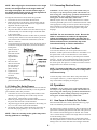
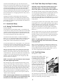
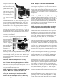
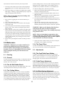
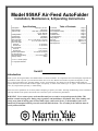
Model 959AF Air-Feed AutoFolder
Installation, Maintenance, & Operating Instructions
Specifications
Table of Contents
Feed Speed . . . . . . . . . . . . . . . . . . . . .18,000 pcs. per hour*
Sheet Capacity . . . . . . . . . . . . . . . . . . . . . . . . . . .200 Sheets
Types of Folds . . . . . . . . . . . . . . .Letter, Half, Z, Double Half
. . . . . . . . . . . . . . . . . . . . . . . . . . . . . . . . .French, Baronial
Feeding Method . . . . . . . . . . . . . . . . . . . . . .Bottom Vacuum
Lightest Paper . . . . . . . . . . . . . . . . . . . . . . . . . . .16# (Bond)
Heaviest Paper . . . . . . . . . . . . . . . . . . . . . . . . . .70# (Bristol)
Max. Paper Size . . . . . . . . .20” x 14 1/16” (66.04 x 35.72cm)
Min. Paper Size . . . . . . . . . . . . . .2” x 3 1/4” (5.08 x 8.26 cm)
Max. Fold Length
First Fold . . . . . . . . . . . . . . . . . . . . . . . . . . .13" (33.02cm)
Second Fold . . . . . . . . . . . . . . . . . . . . . . . . .13" (33.02cm)
Min. Fold Length
First Fold . . . . . . . . . . . . . . . . . . . . . . . . . .1 1/2" (3.81cm)
Second Fold . . . . . . . . . . . . . . . . . . . . . . . .1 1/2" (3.81cm)
Electrical Specifications . . . . . . . . . . .115V 60 HZ (9.5 Amps)
UL CSA Approved . . . . . . . . . . . . . . . . . . . . . . . . . . . . . .Yes
Dimensions (Assembled) . . . . . . . . . . . .23”H X 23”W X41”D
Shipping Weight . . . . . . . . . . . . . . . . . . . . . . . . . . . . .220lbs
1.0 General . . . . . . . . . . . . . . . . . . . . . . . . . . . . . . . . Page 2
2.0 Nomenclature. . . . . . . . . . . . . . . . . . . . . . . . . . . . Page 2
3.0 Pre-Operation SetUp . . . . . . . . . . . . . . . . . . . . . . Page 2
4.0 Operation . . . . . . . . . . . . . . . . . . . . . . . . . . . . . . . Page 4
5.0 Maintenance. . . . . . . . . . . . . . . . . . . . . . . . . . . . . Page 11
6.0 Troubleshooting. . . . . . . . . . . . . . . . . . . . . . . . . . . . . . Page 15
Wiring Diagram . . . . . . . . . . . . . . . . . . . . . . . . . . . . . . . . . Page 16
Parts List. . . . . . . . . . . . . . . . . . . . . . . . . . . . . . . Pages 17, 20
Parts Diagram #1 . . . . . . . . . . . . . . . . . . . . . . . . Pages 18, 19
Parts Diagram #2 . . . . . . . . . . . . . . . . . . . . . . . . . . . . . . . . Page 20
* 8 1/2 x 11 sheet of paper
17” Long Paper Maximum
Serial #
Introduction
Thank you for selecting the Martin Yale Model 959AF Air-Feed AutoFolder. All components have been thoroughly inspected and
performance tested to provide you with the best folder value in its class. Before each machine is packed for shipment, it must
pass a critical performance test, including folding, scoring, and perforating. This folder can execute Half, Double Half, Zee,
French, Baronial, and custom folds within its paper size capacity, as well as Letter Folds (up to 17” paper). The machine can also
score, slit, and perforate separately, or while folding.
Please review this publication in its entirety before attempting to operate your folder. Thorough understanding of this information
will help eliminate most operator-associated errors and ensure years of trouble-free performance.
WARNING! Never connect power to the machine until you are ready to set up and operate the folder. This
machine contains moving parts. During setup, operation, and maintenance keep hands, hair, loose clothing, and
jewelry away from all moving parts. Serious bodily injury could result. Service, or disassembly of side covers
should only be attempted with the power disconnected and locked out. The AC outlet for this machine must be
near by and not blocked.
1.0 General
Controls
Operational setup of the folder is simple and quick. No complicated procedures are involved. A simplified fold chart is prominently displayed on the exit table. The chart corresponds to the
alphabetical letter settings on the fold table scales. See section
4.3 for an example of fold chart.The scales are calibrated in
both inch and metric graduations. The folder features a positive
drive system that requires minimal internal drive maintenance.
The exclusive bottom, air-assisted vacuum feed is engineered
for accuracy and consistency, and eliminates the need to fan
paper before folding. The angle of the feed table and the air-lift
design of the paper guides provides minimal drag on the bottom
sheet as it feeds into the folding rollers. More importantly, this
system ensures smudge-free folding of all paper stocks that fall
within machine parameters. The variable SCR speed control
allows you to customize the speed setting to each application.
Although your folder was thoroughly tested and precision
adjusted before shipment, mis-handling during shipment may
necessitate readjustment. We recommend checking these adjustments before you attempt to operate the folder. See Sections 5.2
& 5.3 in this manual.
1. Right Paper Guide Control
2. Air Control
3. Vacuum Control
4. Vacuum Gauge
Right Side Cover
1.
2.
3.
4.
Circuit Breaker
Power Switch
Paper Feed Speed Dial
Hand Wheel
2.0 Nomenclature
The parts diagrams and parts lists will be used throughout this
manual to describe accessories and parts for your air-feed folder.
3.0 Pre-Operation Folder Setup
Overview
After careful unpacking of the folder place the machine on a
flat, level work surface or stand.
NOTE: The folder weighs 130lbs(unassembled). Use
a mechanical lifting device.
Inspect the machine for signs of damage. If damage is apparent,
call the freight carrier immediately, then call Martin Yale for
instructions. The following items should be unpacked or
installed onto the machine.
1.
2.
3.
4.
5.
6.
7.
1.
2.
3.
4.
5.
6.
7.
8.
Right Side Cover
Exit Table
Receiving Tray
Left Side Cover
Sheet Detector Block
Vacuum Roller
Power Switch
Front Panel
The first and second fold tables.
The feed table.
The feed table paper backstop.
The exit table.
The hand wheel.
The sheet detector, locking knob, and washer.
Three hex key wrenches. (Provided for assembly)
3.1
9. Control Area
10. Feed Table
11. Left Paper Guide
12. Right Paper Guide
13. Pump Vent Guard
14. Conveyor Idler Shaft
15. Conveyor Belt
16. Guide Finger Assembly
Installing The Fold Tables
Both fold tables are alike and can be used in either the
first/upper or second/lower folding position. Each fold table has
two pin slots on each side. One each to the left and right front
of both the open/folding end and the closed/deflector end. The
front slots, one on each side, are for location. The rear slots on
each side are for positioning. The fold tables are supported on
the machine by pins located on the left and right main frame.
The pin locations for the first/upper fold table are above the
upper accessory shaft and the tie rod. The pins for the
second/lower fold table are above the pump guard.
*NOTE: Fold Tables and Hoses are not shown for
clarity.
2
To place the fold
tables onto the
machine, slide the
front slot opening of
the fold table onto
the inner set of pins
(closest to the folding rollers) with a
light forward pressure. Lower the fold table onto the outer set of
pins as shown in Figure 1.
3.4
NOTE: Only the right paper guide air flow can be shut
off.
Fig. 1
3.5
3.6
Installing The Exit Table
Installing The Feed Table
Installing The Timing Block Turnbuckle
Assembly
CAUTION: Both locking nuts on the turnbuckle
assembly must be in the locked position (except
when setting or resetting the timing). Do not rotate
the assembly during installation. Mis-timing may
result.
Install the exit table by
engaging the two tabs
into the slots provided
on the conveyor table
and lowering the exit
table into position as
shown in Figure 2.
3.3
Installing The Sheet Detector
Attach the sheet detector to the sheet detector block (orange
side out) via the locking knob and washer. Slide the sheet detector to the top position and tighten the locking knob. Operational
setting of the detector will be covered later in this manual.
NOTE: When placing the fold table onto the machine
with the deflector end toward the folding rollers, it
may be necessary to rotate the handwheel counterclockwise. When removing the fold table with the
deflector end toward the folding rollers, it may be necessary to rotate the handwheel clockwise. This will
release any tension that may be between the table
and the folding roller.
3.2
Installing The Vinyl Air Hoses
Connect the vinyl air hose extending from the left main frame
to the 90° fitting on the left paper guide. Likewise, connect the
air hose extending from the right main frame to the 90° fitting
on the right paper guide.
Connect the turnbuckle assembly
to the underside of the feed table
as shown in Figure 4. One end of
the turnbuckle is factory installed
to the timing block. A nut, brass
sleeve, and bolt is factory
installed to the other end of the
turnbuckle. Remove the nut and
slide the bolt through the hole in
the underside of the feed table. Tighten the nut and
bolt in place.
Fig. 2
3.7
Fig. 4
Installing The Hand Wheel
CAUTION: Never handle the feed table by the left or
right paper guides. This will cause bending of paper
guides, which will cause improper folding.
Slide the hand wheel onto the shaft extending from the right
machine cover. Lock the handwheel (hex socket) set screw onto
the shaft with the provided hex key wrench.
The feed table has
four location slots,
one each at the front
and on the long side
of the table. The feed
table is supported on
the folder by four
pins. The pins are
located above the
feed roller shaft on
Fig. 3
the left and right
main frame. Place the feed table onto the folder by
engaging the front slots on the table with the pins nearest the
folding rollers. This is best accomplished by inserting the table
nearly vertically into the machine. Once the table slots engage
the pins, lower the table down so the slots on the long side of
the table slide over the other set of pins (See Figure 3).
NOTE: Make sure the set screw is securely tightened
and hand wheel is locked into position.
3.8
The Accessory Shaft Journals
The upper and lower accessory shaft journals extend from the
left machine cover. While these journals are factory installed,
they may have come loose during shipping. Make sure the journal shafts are locked in position by rotating the lower shaft journal clockwise, and the upper shaft journal counterclockwise.
Pull straight out to test. when locked they can not be pulled
out.
3.9
Aligning The Sheet Detector Block
The sheet detector block is located on the top tie rod and is
locked into position via a set screw on top of the block. Align
the front of the sheet detector with the two target marks on the
feed table. The target marks are to the left and right of the vacuum roller.
3
3.11 Connecting Electrical Power
NOTE: When aligning the sheet detector to the target
marks, look straight down on the target marks and
the edge of the paper. Do not look from an angle, or
the alignment will not be correct. Correct alignment is
necessary for efficient paper feeding.
WARNING! Never connect power to the machine until you
are ready to set up and operate the folder. This machine contains moving parts. During setup, operation, and maintenance
keep hands, hair, loose clothing, and jewelry away from all
moving parts. Serious bodily injury could result.
Machine requires 115 VAC 15amp. dedicated circuit. Before
connecting the folder power cord to a dedicated electrical outlet
of the appropriate voltage, be sure the speed control and pump
motor switches are in the off position. Plug the folder power
cord into an electrical outlet of the appropriate voltage and
amperage.
To align the sheet detector block, follow this procedure.
1. Loosen the set screw in the sheet detector block.
2. Rotate the block toward the front of the machine until the
front (orange side) of the sheet detector is in approximate
alignment with the target marks.
3. Place a sheet of paper onto the feed table.
4. Align the sheet detector block so the sheet detector tips are
centered laterally over the left and right countersunk holes
in the vacuum roller.
5. Rotate the hand wheel until the vacuum roller is positioned
so the tips of the detector rest on the flat surface part of the
roller, between the countersunk vacuum holes (when the
detector is lowered).
6. Loosen the detector locking knob, lower the detector until it
touches the round part of the wheel, and lock the detector
locking knob.
7. Slide the sheet of
paper down the
feed table until the
leading edge is
aligned with the
target marks.
8. Move the sheet
detector block until
the sheet detector
just touches the
paper. See Fig. 5
9. Tighten the set
screw in the detector block.
10. Push the sheet
Fig. 5
detector to the top
position and lock the detector locking knob.
CAUTION: Do not use extension cords. Be sure the
folder is connected to an outlet of the appropriate
voltage and amperage. Also make sure there are no
other electrical appliances on the same electrical line.
Failure to observe these precautions may cause
inconsistent folding or machine malfunction.
3.12 Power Check And Test Run
To activate the machine, turn on the speed control switch.
Rotate the variable speed control clockwise to the number 3 on
the speed control scale. Let the machine run a few minutes.
During this initial run, and after any extended period of folder
inactivity, you may hear a muted thumping sound. The sound is
the result of small, flat areas that form on the folding rollers at
the contact point. This process is a normal occurrence and will
disappear after a few minutes of running.
NOTE: You must let the folder run a few minutes after
long periods of inactivity. Failure to do so may cause
inconsistent folding.
Activate the pump motor switch. Basic setup of the folder is
now complete. However, you must complete the operational
setup section before attempting to fold paper.
4.0 Operation
3.10 Setting The Guide Fingers
There are two guide finger assemblies, one each to the left and
right of the sheet detector block assembly. To set the guide finger assemblies, follow this procedure:
1. Unlock the set screw in the locking collar and move each
assembly to approximately three inches away from the
detector block. Center fingers on paper guides.
2. Rotate the guide finger toward the front until the bottom of
the guide clears the surface of the feed table.
3. Align the long part of the guide (attached to the locking collar) so it is 90° to the surface of the feed table.
4. The bottom of the paper guides should clear the surface of
the feed table paper guides by 1/32". See Section 5.2.2.
WARNING! Never connect power to the machine until you
are ready to set up and operate the folder. This machine contains moving parts. During setup, operation, and maintenance
keep hands, hair, loose clothing, and jewelry away from all
moving parts. Serious bodily injury could result.
4.1
How Paper Is Folded On The Folder
When the folder has been correctly adjusted and set up, paper
stock to be folded is placed onto the feed table.
The pump switch is turned on and the air flow is adjusted so the
paper stock is lifted slightly from the feed table. The speed control is turned on and a folding speed is selected. The vacuum
valve is turned slowly clockwise until single sheets are forwarded into the folding rollers.
The following procedure describes how a letter fold is made.
The feed system advances a sheet between the first and second
folding rollers. The sheet then enters the first/upper fold table
NOTE: Failure to correctly set the guides may cause
feeding problems or smudging.
4
and strikes the fold table paper stop. The sheet then enters
between the second and third folding roller where the first fold
is made. The sheet then enters the second/lower folding table
and strikes the fold table paper stop. The sheet enters between
the third and fourth folding rollers where the second fold is
made. The folded sheet then enters between the upper and lower
accessory guide rollers and exits onto the conveyor table. The
sheets are stacked in an overlapping formation as they travel to
the receiving tray.
Although your folder was thoroughly tested and precision
adjusted before shipment, mis-handling during shipment may
necessitate readjustment. We recommend checking these adjustments before you attempt to operate the folder. See Sections 5.2
& 5.3 in this manual.
4.2
Operational Setup
4.2.1 Setting The Sheet Detector
See Parts Diagram.
The sheet detector block assembly (Item 7) is mounted on the
tie rod (Item 73) directly above the vacuum roller. The assembly
consists of a sheet detector block with one block and one nose
pipe set screw, the nose pipe (Item 11), the sheet detector (Item
10), and the locking knob and washer (Item 8 & 9).
The function of the sheet detector is to limit the number of
sheets (1, 2, or 3) entering the folding rollers. The height of the
sheet detector determines the number of sheets entering the
folding rollers, based on the thickness of the sheet(s).
To set the sheet detector, cut a strip of paper 1 3/4" wide and 6"
long from the stock to be folded. Fold the strip in half (1 3/4" x
3"). This strip is the correct thickness and dimension for setting
the gap between the sheet detector and vacuum roller.
Make sure the sheet detector cannot contact the vacuum roller.
Using the hand wheel, rotate the vacuum roller until the sheet
detector will contact the roller on the flat surface between the
countersunk holes. Place the non-folded end of the folded strip
of paper on the vacuum roller between the two rubber rings
(Item 4A). Lower the sheet detector onto the paper strip and
lock into position. See Figure 5.
NOTE: Do not force the sheet detector onto the paper
strip when tightening the knob.
Move the paper strip left to right and check the setting. Verify
each leg is the same height. The sheet detector is correctly set
when a light contact is felt between the the detector, paper, and
vacuum roller. The correct setting of the sheet detector is important and will require practice. If the setting is too loose, more
than one sheet may enter the folding rollers. If the setting is too
tight, no sheets may enter, or intermittent feeding may occur.
The sheets that do advance into the rollers may have marks or
“flecks” on the leading edge.
NOTE: Because paper thicknesses vary and because
of normal wear (See Figure 5.), the sheet detector gap
must be set or reset each time the folder is used.
4.2.2 Feed Table Setup And Paper Loading
CAUTION: Never handle the feed table by the left or
right paper guides. Doing so may cause misalignment of the guides and subsequent folding problems.
The feed table assembly consists of the left paper guide (Item
5C), the right paper guide (Item 5B), the paper guide rod (Item
5A), and the paper centering scale. The paper guides are
attached to aluminum guide blocks. The guide blocks are “V”
slotted. The paper guide rod is inserted through the “V” ways in
the blocks and the guide blocks are locked to the guide rod via
locking knobs.
To set the paper guides for the required paper width, loosen the
locking knobs 1/4 to 1/2 turn. Slide each guide to the required
width as indicated on the centering scale. The centering scale is
located at the front edge of the feed table. (See Figure 6.)
Retighten the locking knob. (The paper guide rod and paper
guides are also adjusted in the field alignment procedure. See
Section 5.3. )
After the paper guides are set, place one sheet of paper between
the paper guides. The sheet should slide freely down between
the guides without excessive side play or binding. Readjust the
right/operators' side paper guide, if necessary until the sheet
slides freely.
NOTE: The paper guides must be set correctly.
Incorrect setting may cause inconsistent, inaccurate,
or wrinkled folds.
Place a 2" stack of the paper to be folded into an Martin Yale
Model 400 or Model 4200 Jogger. Jog the paper for about one
minute. Jogging dissipates static electricity, aligns the edges,
and helps keep sheets from sticking together. Place a 1/2" to
3/4" stack of jogged paper onto the feed table.
4.2.3 Fold Table Setup
See Figures 6, 7, and 8.
Each fold table assembly consists
of an upper and lower fold plate,
an aluminum deflector bar (Item
71N), two fold indicator rulers
(Item 71O), an adjustable paper
stop (Item 71C) with split nut and
locking screw (Item 71M), two
micrometer adjustment screws
(Item 71I) with spring washers
and lock nuts, and adjusting
wheels. (See Figure 10.) Each
fold table has an open/folding
end, and a closed/deflector end.
Fig. 6
The job being processed determines how the fold table is
mounted to the machine. See Section 4.3, Fold Settings, and
Section 4.4, Perforating, Scoring, & Slitting.
5
The position of the fold
table paper stop determines the location of each
fold in the paper. The simplified fold chart (Item
64A) located on the exit
table (Item 64) provides
paper stop settings for five
standard cut paper sizes.
Two are metric (A3 &
A4), and three are inch (8
1/2 x 11, 8 1/2 x 14, 11 x
17).
4.2.4 Setup Of The Feed Table Backstop
The feed table backstop is a one inch angled aluminum fixture
with a magnetic strip attached to one side. The feed table backstop should be used when processing 8 1/2" x 11" (A4) or
smaller stock to prevent sheets from being blown back from the
vacuum roller. Place the magnetic side of the backstop on the
feed table so the vertical side is set against the tail (back) end of
the paper stack.
4.2.5 Setup Of The Stacking Wheel Assembly
The stacking wheel assembly is located at the rear/exit side of
the folder. The function of the stacking wheels is to arrange the
exiting material from the folder into an overlapping stream on
the conveyor table. Generally, the stacking wheels should be
positioned about one inch from the edge of the sheet after the
sheet has dropped to the conveyor table.
Fig. 7
The fold chart refers to “1st”, which corresponds to paper stop
settings on the first/upper fold table, and “2nd”, which corresponds to paper stop settings on the second/lower fold table.
The letters on the fold chart correspond to the letter position on
the fold indicator rulers. The paper stop pointers should be set
so they bisect the circle of the appropriate letter setting.
NOTE: Increasing or decreasing folding speed may
require repositioning the stacking wheel assembly.
Any paper size not shown on the fold chart up to 14" x 18" can
be set on the fold tables by following this procedure. Hand-fold
the sheet into the required fold. Measure the distance between
each fold. Set the paper stops on the first and second fold tables
according to measurements.
The assembly consists of the following. A square shaft with a
compression spring on one side. An angled deflector plate is
attached via two screws to the front of the square shaft. The
stacking wheel shaft extends outward from the center of the
square shaft. Mounted on the stacking wheel shaft are the axle
box housing, the stacking wheel axle, two stacking wheel
weights, and four stacking wheels.
To position, or reposition the paper stop on the fold table,
loosen the locking
knobs on top of the
nylon split nut by two
full turns counterclockwise. A spring
under each split nut
helps disengage the
split nut from the
micrometer rod
threads. Place the
Fig. 8
thumb of your left
hand on top of the left locking knob and the thumb of your right
hand on the right locking knob. With the index and middle finger of each hand, grasp the split nut for control. Slide the paper
stop assembly parallel along the micrometer rods to the required
fold location/measurement. Release the split nut and retighten
the locking knob.
There are two sets of stacking wheel assembly mounting holes
located in the machine side frame, directly in front of the upper
accessory shaft. To mount the assembly, insert the spring end of
the square shaft into one of the two holes in the side frame
(operators' side). Apply pressure (pull) the square shaft laterally
toward the spring end of the shaft. As you do so, align the other
end of the square shaft with the corresponding hole in the other
side frame and release pressure.
To remove the stacking wheel assembly, apply pressure (pull)
the square shaft laterally toward the spring end of the shaft.
Doing so will pull the other end of the square shaft from the
side frame. After the end is clear of the side frame, pull the
entire assembly out of the machine.
For most folding jobs, the deflector plate faces upward. To help
eliminate nesting and to improve the stacking of short folds and
heavier paper stocks, the deflector plate should be faced downward. To do so, remove and reverse (turn over) the stacking
wheel assembly. The deflector plate can also be fine adjusted by
loosening the two mounting screws in the square shaft and lowering the slotted deflector plate up to 1/8". When using the
stripper wire the deflector plate must be removed and the stacking wheel assembly should be installed in the inner set of holes.
CAUTION: Make sure the split nut is correctly
meshed with the rod threads before locking into position. Failure to do so may damage the nut or threads.
Make fold corrections by loosening the locking knobs 1/4 to 1/2
turn. Move the appropriate micrometer wheel in the direction
indicated. Retighten the locking knob.
NOTE: Variations in folding speed will affect fold consistency. Make sure corrections are made at the
speed you intend to fold. If folding is interrupted,
return the speed control to its previous position.
Always clear the conveyor and exit table of folded
material after an interruption. Failure to do so may
cause stacking problems when folding is resumed.
The stacking wheel hook is located on the 1/2" tie rod, below
the first/upper fold table. Use of the hook is necessary when
perforating, scoring, or slitting sheets longer than 12". Simply
rest the stacking wheel shaft in the curved section of the hook.
6
The center valve controls air flow (paper lift) to the feed table
paper guides and the nose pipe. (The nose pipe is located in the
sheet detector block.)
4.2.6 The Simplified Fold Chart
The simplified fold chart located on the exit table provides
paper stop settings for five standard cut paper sizes. Two are
metric (A3 & A4), and three are inch (8 1/2 x 11, 8 1/2 x 14, 11
x 17). The four most popular folds (letter, “Z”, double half, and
half) are illustrated.
The right valve controls the vacuum to the vacuum roller. To
the right of the valve is the vacuum gauge, which indicates how
much vacuum is used to advance sheets into the machine.
The fold chart refers to “1st”, which corresponds to paper stop
settings on the first fold table, and “2nd”, which corresponds to
paper stop settings on the second fold table. The letters on the
fold chart correspond to the letter position on the fold indicator
rulers. The paper stop pointers should be set so they bisect the
circle of the appropriate letter setting.
NOTE: Excessive vacuum can leave marks on the
paper.
4.3
Fold Setup
NOTE: To avoid confusion, the fold chart indicates all
half folds should be made on the second fold table.
However, half folds can be made on either fold table,
depending on the weight of the paper being folded.
Generally, lighter weight stocks should be folded with
the first/upper fold table and heavier stocks with the
second/lower fold table. (See Section 4.2.3.)
4.3.1 Setup For A Letter Fold (8 1/2" x 11"
or A4)
Any paper size not shown on the fold chart up to 14" x 18" can
be set on the fold tables by following this procedure. Hand-fold
the sheet into the required fold. Measure the distance between
each fold. Set the paper stops on the first and second fold tables
according to measurements.
Set the feed table as described in Section 4.2.2. Set the sheet
detector as described in Section 4.2.1. Set the paper stop on the
first/upper fold table to the center of the letter A (G for A4) on
the scales. Set the paper stop on the second/lower fold table to
the center of the letter S (M for A4) on the scales. Move the
paper stops as described in Section 4.2.3. Jog the paper to be
processed on an Martin Yale Model 400 or Model 4200 Jogger,
or hand-jog.
4.2.7 The Speed Control
The speed control is an SCR type control that converts alternating current (AC) to direct current (DC). The folding motor of
the folder is powered by direct current. The speed control is a
combination on/off switch and variable speed regulator. The
control is mounted on the upper left corner of the right (operators') side cover. To activate the feed system of the folder, turn
the speed control clockwise. To incrementally increase the feed
speed, continue to turn the speed control clockwise. To decrease
the feed speed, turn the speed control counterclockwise. To
deactivate the feed system, turn the speed control counterclockwise until it stops.
Remove the first/upper fold table. Turn on the pump motor
switch and manually feed one sheet of paper into the folding
rollers. Turn off the pump motor switch. Manually feed the
sheet through the folding rollers until the sheet edge is in front
of the upper and lower accessory shafts. Set the two upper and
two lower guide rollers on the accessory shafts so they are
equally spaced from the left and right sheet edge. Lock the
guide rollers on the flat part of the shafts.
4.2.8 The Vacuum And Air Controls
Manually feed the sheet past the guide rollers until the sheet
falls onto the conveyor table. Set the stacking wheel assembly
so the distance from the edge of the folded sheet to the center of
the stacking wheel is about 1". The center of the stacking
wheels is the point where the wheels contact the conveyor belt.
Reinstall the first/upper fold table.
See Figure 9.
Extending from the
upper left of the
front panel are
three control valves
and a vacuum
gauge. The left
valve controls the
air flow to the right
feed table paper
guide. The valve
has two settings;
on, and off. Turn
Fig. 9
the valve off when refolding previously folded
stock. (See Section 4.3.5, setup for a french fold, and Section
4.3.6, setup for a baronial fold.) Turn the valve on for all other
applications.
CAUTION: Complete the operational setup sections
before activating the folder.
Turn on the speed control and choose a folding speed setting.
Activate the pump motor switch. Fold several sheets and stop
the machine. Inspect the folded pieces for fold accuracy and
consistency.
NOTE: The letter settings on the fold table scales are
approximate only. Fine fold adjustments must be
7
For any sheet size not listed on the fold chart, fold the sheet in
half by hand. Measure the sheet to the fold. Set the paper stop
according to the measurement.
made with the micro adjustment wheels. This is the
same for all fold styles. See Fig. 10
When the feed
table paper
guides are correctly set and a
consistent fold
speed is maintained, the folded material will
exit the machine
consistently.
After the necessary corrections
are made, complete the folding job.
NOTE: The setup for this fold is identical to 4.3.1 except for
the positioning of the paper stop on the fold table.
Set up the feed table according to Section 4.2.2. Set the sheet
detector as described in Section 4.2.1. Jog the paper to be
processed on an Martin Yale Model 400 or Model 4200 Jogger,
or hand-jog.
4.3.5 Setup For A French Fold
A french fold requires two steps, or passes, through the
machine. During step one, the paper is folded in half and
scored. During step two, the sheet is folded in half again at the
score mark. Also see Section 4.4.
For step one, set up the machine according to instructions in
Section 4.3.4. Set one scoring roller according to the following
procedure.
1. Remove the first/upper fold table.
2. To allow easier access to the upper and lower accessory
shafts, remove the stacking wheel assembly.
3. Half fold a sheet by hand and mark the sheet at the point of
the fold. Place the sheet onto the feed table with the marked
edge toward the folding rollers.
4. Loosen the set screws in the scoring roller and backup hub.
5. Turn on the pump motor switch and with the hand wheel,
manually feed the sheet through the folder until the marked
edge extends to the upper accessory shaft. (Turn off the
pump motor switch after the sheet enters the first folding
roller.)
6. Align the scoring roller with the mark on the sheet and lock
the roller onto the flat part of the shaft.
7. Manually feed the sheet out of the machine.
8. Disengage the lower accessory shaft journal by first rotating
the journal counterclockwise. Now pull straight out on the
journal. (If the journal is difficult to remove, place the hex
key wrench through the hole in the journal and pull out.)
9. Slide the backup hub until the grooved part of the backup
hub aligns with the point on the scoring wheel.
10. Engage and lock the lower accessory shaft journal by aligning the shaft and journal, reinserting the journal into the
accessory shaft, and rotating clockwise.
11. A slight amount of movement in the backup hub will help
ensure adequate scoring without cutting through the paper.
Tighten the set screw in the hub onto the flat part of the
shaft only to the point where a slight amount of side-to-side
movement is apparent in the hub.
12. Reinstall the first fold table and stacking wheel assembly.
13. Fold one sheet according to instructions in Section 4.3.4 and
check the score mark locations. Adjust the scoring wheel, if
necessary, until the paper is scored in the correct position for
refolding.
NOTE: If the paper is cut through during the scoring
process, round off the point of the scoring roller with
a fine file or emery.
Fig. 10
4.3.2 Setup For A Z Fold (8 1/2" x 11" or A4)
NOTE: The setup for this fold is identical to 4.3.1 except for
the positioning of the paper stop on the fold table.
Set the feed table as described in Section 4.2.2. Set the sheet
detector as described in Section 4.2.1. Set the paper stop on the
first/upper fold table to the center of the letter B (P for A4) on
the scales. Set the paper stop on the second/lower fold table to
the center of the letter S (M for A4) on the scales. Move the
paper stops as described in Section 4.2.3. Jog the paper to be
processed on an Martin Yale Model 400 or 4200 Jogger, or hand
jog.
4.3.3 Setup For A Double Half Fold
17" or A3)
(11" x
NOTE: The setup for this fold is identical to 4.3.1 except for
the positioning of the paper stop on the fold table.
Set the feed table as described in Section 4.2.2. Set the sheet
detector as described in Section 4.2.1. Set the paper stop on the
first/upper fold table to the center of the letter L (N for A3) on
the scales. Set the paper stops on the second/lower fold table to
the center of the letter T (Q for A3) on the scales. Move the
paper stops as described in Section 4.2.3. Jog the paper to be
processed on an Martin Yale Model 400 or 4200 Jogger, or hand
jog.
4.3.4 Setup For A Half Fold (Single Fold)
(8 1/2" x 11" or A4)
If your wish to score, slit, or perforate the half fold, see Section
4.4 for instructions.
Insert the first fold table into position with the folding (open)
end toward the fold rollers. The second fold table is placed into
position with the deflecting (closed) end toward the fold rollers.
Set the paper stop on the first fold table to the setting as shown
on the folding chart.
NOTE: Although half folds can be made with either
fold table, the first fold table provides better accuracy
on regular and lightweight paper stocks. However, to
reduce crushed folds and to minimize curl when
heavier stock is folded, utilize the second fold table.
14. Once the scoring mark is in the correct location, run the job
through the folder.
8
For step 2, follow this procedure.
1. Remove the first fold table and the stacking wheel assembly.
2. Disengage the scoring wheel backup hub by rotating the
accessory shaft journal counterclockwise and pulling out.
Loosen the set screw in the hub and move the hub away
from the scoring wheel. Reengage the accessory shaft journal by aligning the shaft and journal, reinserting the journal
into the shaft, and rotating clockwise.
3. Set the sheet detector according to instructions in Section
4.2.1 for double thickness (four single sheets).
4. Set the folder up as described in Section 4.3.4.
lock each roller onto the flat part of the shaft.
7. Manually feed the sheet out of the machine.
8. Disengage the lower accessory shaft journal by first rotating
the journal counterclockwise. Now pull straight out on the
journal. (If the journal is difficult to remove, place the hex
key wrench through the hole in the journal and pull out.)
9. Slide the backup hub until the grooved part of the backup
hub aligns with the point on the scoring wheel. Repeat this
procedure for the other scoring wheel.
10. Engage and lock the lower accessory shaft journal by aligning the shaft and journal, reinserting the journal into the
accessory shaft and rotating clockwise.
11. A slight amount of movement in the backup hubs will help
ensure adequate scoring without cutting through the paper.
Tighten the set screw in the hubs onto the flat part of the
shaft only to the point where a slight amount of side-to-side
movement is apparent in the hubs.
12. Reinstall the first fold table and stacking wheel assembly.
13. Fold one sheet according to instructions in Section 4.3.4 and
check the score mark locations. Adjust the scoring marks, if
necessary, until the paper is scored in the correct positions
for refolding into a letter fold.
14. Once the scoring marks are in the correct locations, run the
job through the folder.
NOTE: When setting the paper guides, place the folded edge to the left paper guide and the open side to
the right paper guide. This step is important because
only the right guide air flow can be turned off. This is
the same for all fold styles.
5. Measure the sheet from the edge to the center of the score
mark and set the appropriate fold table paper stop to the
measurement.
6. Turn the air control valve for the
right paper guide to the off position.
7. Set the vacuum to maximum and the
air flow to minimum.
8. Set the guide rollers on the accessory shafts.
9. Test fold several sheets and check
the folds for accuracy. Adjust the
paper stop, if necessary, until the
paper is folded directly on the score
mark.
10. Run the entire folding job through
the folder.
Fig. 11
For step 2, follow this procedure.
1. Remove the first fold table and the stacking wheel assembly.
2. Disengage the scoring wheel backup hub by rotating the
accessory shaft journal counterclockwise and pulling out.
Loosen the set screw in the hub and move the hub away
from the scoring wheel. Reengage the accessory shaft journal by aligning the shaft and journal, reinserting the journal
into the shaft, and rotating clockwise.
3. Set the sheet detector according to instructions in Section
4.2.1 for double thickness (four single sheets).
4. Set the folder up as described in Section 4.3.1.
5. Measure the sheet from the edge to the center of the first
fold score mark and set the appropriate fold table paper stop
to the measurement. (See Figure 11.) Set the second fold
table paper stop to the measured distance to the score mark.
6. Turn the air control valve for the right paper guide to the off
position.
7. Set the vacuum to maximum and the air flow to minimum.
8. Set the guide rollers on the accessory shafts.
9. Test fold several sheets and check the folds for accuracy.
Adjust the paper stops, if necessary, until the paper is folded
directly on the score marks.
NOTE: It may be helpful to set the stacking wheel
assembly with the deflector in the down position.
4.3.6 Setup For A Baronial Fold
A baronial fold requires two steps, or passes, through the
machine. During step one, the paper is folded in half and scored
in two places. During step two, the half fold is refolded into a
letter fold along the two score marks.
For step one, set the machine up as described in Section 4.3.4.
Set two scoring wheels according to the following procedure.
1. Remove the first/upper fold table.
2. To allow easier access to the upper and lower accessory
shafts, remove the stacking wheel assembly.
3. Half fold a sheet by hand and mark the sheet at the points
where it will be refolded into a letter fold. Place the sheet
onto the feed table with the marked edge toward the folding
rollers.
4. Loosen the set screws in the scoring rollers and backup
hubs.
5. Turn on the pump motor switch and with the hand wheel,
manually feed the sheet through the folder until the marked
edge extends to the upper accessory shaft. (Turn off the
pump motor switch after the sheet enters the first folding
roller.)
6. Align the scoring rollers with the marks on the sheet and
10. Run the entire folding job through the folder.
4.4
Setup For Perforating, Scoring, and
Slitting
The folder can be used to
fold and individually or
simultaneously slit, perforate, or score paper, depending on job requirements. Fig. 12
As seen in Figure 12, there are two scoring rollers, one 7-tooth
9
per-inch perforating wheel, and two rubber guide rollers on the
upper accessory shaft. On the lower shaft are two backup hubs,
and two steel guide rollers. An optional slitter, and 3-tooth and
14-tooth perforator are available as options.
6. Set the scoring roller by loosening the set screw with the
provided hex key wrench. Align the scoring roller(s) to the
mark(s) on the sheet of paper and lock into position on the
flat part of the accessory shaft. Loosen the set screw in the
backup hub(s). Disengage the lower accessory shaft journal
by rotating the journal a fraction of a turn counterclockwise,
and pulling the journal out of the shaft. (If the journal is difficult to remove, place the hex key wrench through the hole
in the journal and pull out.) Slide the backup hub(s) until the
grooved part of the backup hub(s) aligns with the point on
the scoring wheel(s). Engage and lock the lower accessory
shaft journal by aligning the shaft and journal, reinserting
the journal into the accessory shaft and rotating clockwise.
7. Set the upper and lower paper guide rollers 1/4" from the
paper margins.
8. Install the stacking wheel assembly. For sheets up to 12"
long, the rollers of the stacking wheel assembly should rest
on the conveyor table. For sheets longer than 12", the stacking wheel shaft should be lifted and placed into the stacking
shaft hook. The hook is located on the 1/2" tie rod, below
the first/upper fold table.
9. Place both the first/upper and second/lower fold tables into
position with the closed/deflector end toward the folding
rollers. (This allows the paper to travel through the machine
without being folded.) As the sheet moves between the
upper and lower accessory shafts, the perforating, scoring,
or slitting is facilitated. The sheet then exits onto the conveyor table.
The rubber and steel guide rollers control the paper as it exits
the folding rollers and help guide the material onto the conveyor table. The rollers should always be positioned with their
outer edges approximately 1/4" from the paper margins.
NOTE: Failure to set the guide rollers correctly may
cause inaccurate scoring, slitting, or perforating.
It is important to set the backup hubs to
the intended scoring, slitting, or perforating operation. The slitting or perforating
wheels should be set to the machined
(sharpened) side of the hub, opposite
from the “V” groove. The high point of
the scoring wheel(s) should be aligned in
the “V” grooves of the backup hub(s).
(See Figure 13.)
Fig. 13
CAUTION: Failure to correctly set the perforating,
scoring, or slitting wheels with the backup hubs may
cause permanent damage to the accessories.
To engage the perforating, slitting, or scoring rollers, follow this
procedure.
1. Mark a sheet of paper at the point to be perforated, scored,
or slit.
2. Set the feed table paper guides so the marked sheet slides
freely down between the guides without excessive side play.
Lightweight papers may wrap around the wheel when perforating. On these occasions, simply install the stripper wire around
the wheel. The stripper wire (which resembles a large safety
pin) is located on the 1/2" tie rod below the first/upper fold
table. To install the wire, remove it from the tie rod and place
the open end around the left and right side of the perforator.
Loosen the two retaining screws and remove the deflector plate
from the stacking wheel cross shaft. Retighten the two screws.
Place the stacking wheel assembly into the inner hole position
in the machine side frames. Close the stripper wire around the
shaft. (See Figure 14.)
NOTE: To ensure consistency when perforating,
scoring, or slitting, the feed table paper guides must
be set correctly.
3. Remove the first/upper fold table and stacking wheel assembly.
4. Turn on the pump motor switch and with the hand wheel,
manually feed the sheet through the folder until the marked
edge extends to the upper accessory shaft. (Turn off the
pump motor switch after the sheet enters the first folding
roller.)
5. Set the perforator or the slitting wheel by loosening the set
screw with the provided hex key wrench. Align the perforator or slitter to the mark(s) on the paper and tighten the set
screw(s) on the flat part of the shaft. Loosen the set screw in
the backup hub(s) on the lower accessory shaft. Slide the
machined (sharpened) side of the backup hub(s) against the
perforating or slitting blade. Hold the hub(s) against the
blades and lock the hubs into position on the flat part of the
shaft.
Fig. 14
NOTE: If the paper is cut through during the scoring
process, round off the point of the scoring roller with
a fine file or emery.
CAUTION: Failure to lock the accessories into position on the flat part of the upper and lower accessory
shafts may damage the shafts and prevent free lateral
movement of the accessories.
4.5
Start-Up
This procedure assumes the folder is correctly set up for folding, perforating, scoring, or slitting. If not, follow the appropri-
10
ate instructions in Section 4.2 for the job to be processed.
clean the folding rollers. Use of any other cleaning product may
damage the rollers. Rubber Roller Cleaner & Rejuvenator is
available from your Martin Yale Dealer, or from Martin Yale.
1. Turn the air and vacuum control valves to the off position.
(For refolding, also turn off the right paper guide air flow
valve.)
2. Jog a stack of paper on an Martin Yale Model 400 or Model
4200 Jogger, or hand-jog. Jogging fluffs the paper, aligns the
edges, and dissipates static electricity.
To clean the folding rollers, follow this procedure.
1. Remove the feed table, folding tables, the stacking wheel
assembly, and the top roller cover.
2. Liberally spray Martin Yale Rubber Roller Cleaner onto a
clean, dry cloth.
3. Briskly clean the exposed surface of all four folding rollers
until no more contaminant appear on the cloth.
4. Turn the hand wheel to expose uncleaned surfaces and continue cleaning until all surfaces are smooth and resilient, not
hard or slick.
5. After all roller surfaces are clean, restore power to the
machine. Turn on the speed control and run the rollers at
medium speed until all roller cleaner residue has evaporated.
NOTE: Failure to jog paper may cause feeding, folding, and stacking problems.
3. Place a stack of jogged paper onto the feed table for processing.
4. Turn on the pump motor switch.
5. Slowly turn the air control valve clockwise until the paper
stack begins to lift.
6. Turn on the speed control and select a feed speed (usually
between 4 & 7 on the scale) by rotating the speed control
knob clockwise.
7. Slowly rotate the vacuum valve clockwise until paper sheets
begin to advance from the feed table into the folding rollers.
Some fine tuning of the air and vacuum control valves may
be necessary for optimum feeding. Optimum feed speed for
each application will vary with the condition of the machine,
operator skill and ability, the job being processed, and the
stock being run.
8. Run the entire job through the machine according to instructions.
WARNING! Make sure all cleaning cloths have been
removed from the roller area before starting the
machine. Keep hands, fingers, loose clothing and jewelry
away from the rollers.
NOTE: Failure to immediately evaporate the roller
cleaner residue may cause the rollers to bond together. Bonding may damage the rollers, the drive system,
or the feed motor and void the warranty.
6. Inspect the rollers to make sure they are clean, and inspect
for damage or wear. Replace, if necessary.
5.0 Maintenance
WARNING! Maintenance procedures should only be
performed by qualified personnel. Disconnect power
from the machine before attempting any maintenance
procedure. Service, or disassembly of side covers should
only be attempted with the power disconnected and
locked out.
5.1.4 The Pump Filters
5.1
A number of circumstances may cause the feed table paper
guides to become misaligned. To correct the paper guides, follow instructions in Section 5.3.2. To reset the guides when
changing paper sizes, follow instructions in Section 4.2.2.
As often as needed (but at least monthly), remove the front and
rear covers and clean the vacuum and air pump filters.
5.2
Adjustments
5.2.1 The Feed Table Paper Guides.
Cleaning
5.1.1 General
As often as needed (but at least weekly), vacuum paper dust and
other contaminant from the folder. Clean the main body of the
machine with a soft, dry cloth.
5.2.2 Guide Finger Adjustment.
As often as needed, clean the air roll rubber bands with a clean
cloth dampened with a mild soap and water solution.
Correct setting of the guide fingers is necessary for efficient
feeding. The guide fingers prevent the paper from lifting too
high off the feed table. Incorrect setting of the guide fingers
may cause streaking, smudge marks, and paper infeed problems.
Follow instructions in Section 3.10 to correctly set the guides.
5.1.3 The Folding Rollers
5.2.3 Air Block Spring Adjustment.
5.1.2 The Air Roll Rubber Bands
Contaminated folding rollers can cause a variety of problems,
including inconsistent folding, wrinkling, jamming, and misfeeding. While the folding rollers of the folder are resistant to
chemicals in carbonless paper, toner, ink, and other contaminates will build up on the roller. Clean the folding rollers after
every folding job. Regular cleaning will increase roller longevity. Always use Martin Yale Roller Cleaner & Rejuvenator to
The air block must remained sealed against the air feed roll to
ensure consistent feeding. The air block spring is located on the
feed roll shaft at the left side of the air block. The spring applies
pressure to the block to ensure the seal against the vacuum
roller and is held in place by a set collar. Too much pressure
may also cause feeding problems.
11
To correctly set the spring tension, loosen the screw in the set
collar. Pull the collar away from the spring until there is no
pressure on the block. Push the collar and spring against the air
block and continue to push until the spring is compressed 3/4".
Lock the screw in the set collar.
2. Remove the speed control, pump motor switch, hand wheel,
the circuit breaker, and the six right side cover mounting
screws. Remove the cover.
3. The fold motor is located on the inside of the right main
frame with the motor shaft extending through the frame. The
motor is held in place by four screws that extend through
the frame. The timing belt connects the motor pulley with
the 60T timing pulley located on the main drive roller.
Loosen the four motor mounting screws. Set the belt tension
with a belt tension gauge. If a gauge is unavailable, set the
tension so the belt deflects about 1/4". Reinstall the cover
and components in reverse order.
5.2.4 Paper Guide Rollers.
The paper guide rollers are located two each on the upper and
lower accessory shafts. The upper rollers are rubber-covered
steel while the lower rollers are steel. Each roller has a set
screw and should be locked into position on the flat part of the
shaft.
The guide rollers function to control the last two to three inches
of the sheet as it exits the folding rollers, especially during slitting, scoring, and perforating. Set and align the guide rollers to
approximately 1/4" from the paper margins to prevent skewing.
(See Figure 12 page 9)
5.3
Machine Alignment
5.2.5 Angular Control Adjustment.
A number of reasons may cause misalignment, including tampering, machine relocation, or excessive wear. Correct alignment is essential for successful operation of the folder. See
Section 2.0 to orient yourself to the areas referred to in this procedure.
CAUTION: This procedure, sometimes referred to as
field alignment, should be performed only by qualified
service personnel.
Paper skewing to the right or left on the feed table (after entering the first folding roller) can be corrected by increasing or
decreasing the spring tension (changing the angle) on the second folding roller. The adjustment screw can be accessed
through the hole in the right side cover. (See Section 5.3.8.)
CAUTION: The paper used for this alignment is
important. 20# or 24# bond is ideal. The paper should
be straight and parallel on the long edges, and perpendicular to the sides. Use of paper that has not
been cut accurately may result in misalignment.
Sheets used during this alignment should not be
reversed or turned over. Always use the same edge of
the sheet as the lead edge. Failure to follow this procedure may invalidate the alignment process.
NOTE: This adjustment is factory set and should only
require readjustment if the roller spring is worn or a
gap exists between the first and second folding
rollers, or it becomes impossible to score, slit, or perforate parallel to stock edges. Do not make this
adjustment until you are sure the paper guides are
parallel with each other, and that they are perpendicular to the folding rollers. You must also be sure the
paper is cut squarely. A crooked fold can be compensated for by utilizing the fold table micrometer
wheels. (See Fig. 10 page 8)
5.3.1 Neutral Position
To begin the alignment procedure, first set the machine to a
neutral position according to the following procedure.
1. Place the folder on a flat, level work surface or stand. Check
the base plate to make sure all four pads are in place.
2. Thoroughly clean all four folding rollers according to
instructions in Section 5.1.3.
3. Install both fold tables with the closed/deflector end toward
the folding rollers.
4. Lift the sheet detector to its top position and lock into place.
5. Loosen the left and right locking nuts on the turnbuckle
assembly.
6. Install the feed table but do not connect the air hoses.
7. Set the paper guides to maximum paper width.
8. Connect the turnbuckle assembly to the feed table.
9. Adjust the turnbuckle so the top front of the air block contacts the bottom of the feed table.
10. Set the paper guide cross shaft on the feed table to the center of the 5/8" slot and lock into position.
11. Insert the provided hex key wrench through the hole in the
right side cover and into the alignment adjusting screw. Turn
the adjusting screw until there is no pressure on the spring
adjustment. (The spring exerts pressure on the second folding roller.) Turn the set screw 3 1/2 turns clockwise.
To make the adjustment, insert the supplied hex key wrench
into the adjusting screw inside the right side cover. Clockwise
rotation will result in paper pulling more to the right.
Counterclockwise rotation will result in paper pulling more to
the left.
CAUTION: Excessive counterclockwise adjustment
may result in the screw leaving its station and falling
into the inside cover.
5.2.6 Timing Belt Adjustment
The timing belt may stretch as a normal process of operation
and the tension must be reset, or the tension must be set correctly when installing a new belt. If the belt is set too loosely, it
may fall off. It it is set too tightly, it may stress the motor shaft.
Have a qualified service person check the line amperage. The
amperage should not exceed 3.2 Amps. To access the motor and
timing belt, qualified personnel should follow this procedure.
1. Disconnect power to the machine.
12
2. Shorten the turnbuckle assembly by making 4 1/2 turns with
the buckle and bring the locking nuts in contact with the
buckle. Do not lock the nuts in position at this time.
3. Either by turning the vacuum roller forward by hand, or by
using the hand wheel to manually forward the machine,
align the edges of the countersunk holes in the vacuum
roller with the front of the sheet detector.
4. Place a sheet of paper over the holes in the vacuum roller.
Plug in the machine. Turn on the pump motor switch and
adjust the vacuum control knob to maximum. The sheet
should be pulled down into the vacuum roller and the vacuum gauge should read 20 or higher. If the gauge does not
read 20 or higher, readjust the turnbuckle in 1/4 to 1/2 turn
increments until the gauge reads 20 or higher.
5. Turn the pump motor switch off.
5.3.2 Paper Guide Alignment
The folder is now in a neutral position and ready to be adjusted
so sheets of paper enter correctly into the folding rollers. To
align the paper guides, follow this procedure.
1. Open the feed table paper guides to their maximum open
position.
2. Place an 11" x 17" (or A3) sheet onto the feed table and
slide the sheet down until the leading edge is between the
first and second folding rollers.
3. Carefully set the paper guides until they are within 1/16"
from the long side of the sheet.
CAUTION: At no time touch or otherwise move the
sheet out of position. Doing so may compromise the
alignment. If you suspect the sheet has moved, repeat
steps 1 through 3.
5.3.5 Nose Pipe
4. Observe the long axis of the guides and the sheet edge. If
they appear to be parallel, no adjustments are required.
5. If the guides are not parallel to the sheet edges, adjust one
guide at a time until they are by first loosening the hex socket cap screw on the paper guide block. Move the guide until
it is parallel with the sheet edge. Do not move the sheet out
of position! Lock the guide into position by retightening the
cap screw.
6. Repeat this procedure for the other paper guide.
7. Remove the sheet from the feed table.
8. Connect the left and right paper guide air hoses.
The nose pipe in the sheet detector block serves to inject air into
the leading edge of the paper stack to facilitate smooth feeding.
Check the setting of the nose pipe by following this procedure.
1. Place a 1/8" to 1/4" stack of 11" x 17" (or A3) paper onto
the feed table. Disconnect the air lines from the paper guides
and turn on the pump motor switch. Adjust the air and vacuum knobs to maximum. With your thumbs, block off the
paper guide air hoses. Observe the rear of the paper stack. If
the nose pipe is correctly adjusted, the bottom 3 to 6 sheets
should flutter.
2. If the sheets are not fluttering, loosen the set screw (in the
sheet detector block) that locks the nose pipe in position.
Rotate the nose pipe until the sheets flutter. Before retightening the set screw, make sure the nose pipe air holes align
with the rubber bands on the air feed roll. Reconnect the air
lines to the paper guides.
5.3.3 The Sheet Detector Block
The next step in the alignment procedure is to align the sheet
detector block. Do so by following this procedure.
1. Loosen the hex socket set screw located on top of the sheet
detector block.
2. Place a sheet of 11" x 17" (or A3) paper onto the feed table
and set the paper guides so the sheet slides freely between
the guides without excessive side play.
3. Slide the sheet down so the front of the sheet aligns with the
target marks on the feed table. The target marks are to the
left and right of the vacuum roller.
4. Lower the sheet detector.
5. Look straight down on the target marks and move the detector block so the front of the sheet detector contacts the sheet
edge and aligns with the target marks. Also make sure the
sheet detector tips are aligned laterally with the left and right
holes in the vacuum roller. Retighten the set screw in the
sheet detector block.
5.3.6 Feed System Test
Set the sheet detector according to instructions in Section 4.2.1.
Start the folder according to instructions in Section 4.5. When
correctly adjusted, you will hear a distinctive “swooshing”
sound as paper is feeding into the folder. (You can hear this
sound on the enclosed video presentation.) If you do not hear
the sound, adjust the turnbuckle in 1/4 to 1/2 turn increments
until the sound is produced. Turn off the machine.
5.3.7 The Feed Table Cross Shaft
The next step in machine alignment is to check positioning of
the stacking wheel cross shaft. Do so by following this procedure.
5.3.4 Timing Block
1.
2.
3.
4.
5.
Place the stacking wheel shaft into the stacking wheel hook.
Place a full stack of paper onto the feed table.
Turn on the speed control and set to minimum speed.
Turn on the pump motor switch.
Run two or three sheets through the machine and turn off
the speed control and pump motor switch when the trailing
end (3" to 5") of the fourth sheet is still between the paper
guides.
6. Pull back the stack of paper on the feed table and observe
the tail end of the sheet. If the sheet lays flat on the feed
Correct setting of the timing block (located on the left side of
the vacuum roller) is necessary for correct feeding. The block is
set via the turnbuckle assembly. One end of the turnbuckle
assembly is attached to the timing block and the other end is
attached to the feed table. Set the timing block according to this
procedure.
1. Make sure the front end of the timing block is in contact
with the feed table as indicated in Section 5.3.1.
13
table, no cross shaft adjustment is necessary. If the paper
does not lay flat on the feed table (climbs up the right or left
paper guide), adjust the feed table cross shaft.
7. Loosen the cross shaft hex head set screw on the side of the
feed table. If the sheet is climbing the right paper guide,
observe the gap between the left paper guide and the sheet.
Place a prying tool (bar, wrench, or screwdriver) between
the shaft and table. Move the shaft away from the folding
rollers a distance equal to 1/2 of the gap between the left
paper guide and the sheet. If the sheet is climbing the left
paper guide, observe the gap between the right paper guide
and the sheet. Place a prying tool (bar, wrench, or screwdriver) between the shaft and table. Move the shaft toward
the folding rollers a distance equal to 1/2 of the gap between
the right paper guide and the sheet.
8. Manually feed the sheet through the machine. If it exits the
machine wrinkled, discard the sheet. Otherwise place it back
on the feed table and repeat steps one through seven until
the sheet lays flat between the paper guides.
the machine to jam. If a jam should occur, follow this procedure.
1.
2.
3.
4.
5.
Turn off the speed control and pump motor immediately.
Unplug the machine.
Remove the fold tables (if necessary).
Remove the stacking wheel assembly.
Remove the jammed paper using manual rotation of the
hand wheel (if necessary).
CAUTION: The jam must be cleared from the machine
before restarting. If the jam was severe enough to
stall the motor, the circuit breaker may have activated
(tripped). Allow several minutes for the motor and
breaker to cool. Push the reset button on the circuit
breaker.
6. Determine the cause of the jam and remedy the problem.
See Section 6.6 for possible causes of jams.
7. Install the fold tables and the stacking wheel assembly. Plug
the machine in and resume operation.
CAUTION: Sheets used during this alignment should
not be reversed or turned over. Always use the same
edge of the sheet as the lead edge. Failure to follow
this procedure may invalidate the alignment process.
5.5
Circuit Breaker Activation
Make sure the folder is plugged into a dedicated line. If the
folder circuit breaker activates (trips) continuously, have a qualified service technician check the following.
5.3.8 The Angular Control Adjustment
The next step in the alignment process is to fine tune the alignment via the angular control adjustment. (See Section 5.2.5.) To
do so, follow this procedure.
1. Place a stack of paper onto the feed table, turn the speed
control on low, and turn on the pump motor switch.
2. Observe the sheets as they move into the folding rollers. If
there is a narrow gap between the sheet edge and either
paper guide, use the angular adjustment screw to correct the
gap. (Turn the screw only in 1/4 to 1/2 turn increments and
no more than 1 1/2 complete turns. If the sheet is moving to
the left after entering the folding rollers, turn the screw
clockwise while the machine is running. If the sheet is moving to the right, turn the screw counterclockwise while the
machine is running. Making the appropriate adjustment
while the machine is running will allow you to watch the
results of the adjustment.
3. Adjusting the screw while the machine is running will virtually always render the best results. If, for some reason, the
sheets do not enter the folding rollers in a straight manner,
repeat instructions in Section 5.3.1, Section 5.3.7.
4. As a final check, set up the machine to perforate an 11" x
17" sheet in the center according to instructions in Section
4.4. Fold the sheet along the perforation and check to make
sure the (long) sheet edges are parallel. Minute adjustments
can be made with the adjustment screw in 1/8 to 1/4 turn
increments.
1. The line amperage to the DC folding motor. The reading
should not exceed 3.2 amps. If the reading is more than 3.2
amps, the technician should check all gears and bearings for
adequate lubrication. Make sure the machine is resting on a
flat, level surface, and that all four pads are in place on the
bottom of the machine. Check the timing belt tension.
2. The circuit breaker, speed control, and fold motor. Replace,
as needed.
3. The electrical line for fluctuations.
5.6
Lubrication
5.6.1 The Folding Roller Bearings
The folder should be lubricated every eight hours of machine
operation according to the following procedure.
1. Turn off the machine and disconnect and lock out power.
2. Clean the folding rollers according to instructions in Section
5.1.3.
3. Remove any accumulated lint or dust from the ends of the
folding roller shafts and the shaft bearings with a brush or a
clean, dry cloth.
4. Lubricate the bearings at the ends of the folding roller shafts
with one drop of light machine oil in each bearing.
Your folder is now correctly aligned.
5.4
CAUTION: Do not drop oil onto the rubber portion of
the folding rollers. If oil is spilled on the rollers,
remove it immediately with Martin Yale Rubber Roller
Cleaner & Rejuvenator.
Clearing A Jam
When the folder is set up correctly, jams are unlikely to occur
because of a machine malfunction. However other factors
(humidity levels, paper quality, operator error, etc.) may cause
14
5.6.2 The Vacuum And Air System
6.4
The pump motor, vacuum, and compressor pumps do not
require lubrication.
The vacuum may be set too high. Check the settings according
to instructions in Sections 4.1, 4.2.8, and 4.5. The guide fingers
may be set incorrectly. See Sections 3.10 and 5.2.2. The folding
rollers may be dirty or excessively worn. Clean according to
instructions in Section 5.1.3. After cleaning, rotate the hand
wheel slowly and observe the area between the folding rollers.
A gap between the first and second rollers on the right side may
indicate a need for angular control adjustment. See Sections
5.2.5 and 5.3.8. Gaps in any other location may indicate a need
to replace the folding rollers, the folding roller springs, or the
folding roller bearings.
6.0 Troubleshooting
The following guide will help you identify the causes and provide solutions for the most common operational problems of the
folder.
6.1
The Motors Will Not Start
There may be no power flowing to the machine. Make sure the
machine is connected to an active AC outlet of the appropriate
voltage and amperage. The folder requires a dedicated 115 volt,
15 amp, or 220 volt 10 amp line.
6.5
6.6
CAUTION: If the circuit breaker trips again immediately, a more serious problem may be indicated.
Notify a qualified service technician.
The Paper Jams Or Tears
See Section 5.4
Paper jams or tears may be caused by double sheeting. Double
sheeting may be caused by paper that is not correctly jogged,
ink that is not dry, incorrect setting of the sheet detector, or
incorrect setting of the speed, vacuum, or air. Jog the paper,
allow adequate drying time for inks. See Sections 3.5, 3.9, 4.1,
4.2.7, 4.2.8, 4.5. The folding rollers may be contaminated.
Clean the rollers according to instructions in Section 5.1.3. The
folding speed may be too high for the paper stock being folded.
Adjust the feed speed according to instructions in Section 4.2.7.
The stacking wheel assembly may be misadjusted. Adjust the
stacking wheel assembly according to instructions in Section
4.2.5. Paper may have wrapped around the perforating wheel.
Install the stripper wire as instructed in Section 4.4. The conveyor belts may not be turning. Check the belt shaft, the tension
springs, and the conveyor drive belt. Replace parts as needed.
The stacking wheel assembly may not be set properly. Set the
stacking wheel according to instructions is Section 4.2.5. The
paper guide rollers may not be set properly. Set the rollers
according to instructions in Section 5.2.4. The stacking wheels
may have seized. Check the stacking wheels and repair or
replace as needed.
One or more electrical components may be faulty. Have a qualified technician check the electrical components. Also have the
technician check all wiring connections. The bearings may need
lubrication. Lubricated according to instructions in Section 5.6.
The folding motor belt may be loose or may not be adjusted
correctly. (See Section 5.2.6.)
Paper Will Not Feed
There may be a paper infeed problem. The sheet detector may
be set incorrectly, or may be worn. The sheet detector block
may be set incorrectly. See Sections 3.9 and 4.2.1. The timing
block spring may not be set correctly. See Section 5.2.3. The
bearing in the vacuum roller may be worn. The vacuum roller
should turn freely toward the folding rollers, but not backward.
Replace the bearing. The paper guides may be set incorrectly.
See Section 4.2.2. The air and vacuum settings may be incorrect. See Sections 4.1, 4.2.8, and 4.5. The guide fingers may be
set incorrectly. See Sections 3.10 and 5.2.2. The feed table
backstop is not set correctly, or is not in use. See Section 4.2.4.
The vacuum and air pump filters may be clogged. See Section
5.1.4. The paper may be excessively curled. Turn the paper over
on the feed table and check the setting of the guide fingers
according to instructions in Sections 3.10 and 5.2.2.
6.3
Flecking
Flecking appears on the leading edge of the sheet as one or two
nicks in the paper. Flecking is caused by incorrect setting of the
sheet detector. Set the sheet detector according to instructions in
Sections 3.5, 3.9, and 4.2.1.
The folder circuit breaker may have activated (tripped). Turn off
the speed control. Let the circuit breaker cool down then push
the reset button.
6.2
The Paper Wrinkles
6.7
Crooked Paper Folds
The paper may not be folding squarely. Adjust the fold table
paper stops according to instructions in Sections 4.2.3. Also see
Section 4.2.8. The folding rollers may be contaminated. Clean
the folding rollers according to instructions in Section 5.1.3.
Flecking may be occurring. Set the sheet detector according to
instructions in Sections 3.5, 3.9, and 4.2.1. The paper may not
be cut squarely/parallel. Recut the paper.
The Length Of Fold Varies
The feed speed during operation may not be the same speed at
which the machine was set up. See Sections 4.1, 4.2.3, and
4.2.7. Line voltage fluctuations may be occurring. See Section
5.5. The paper stop retaining screws on the bottom of the fold
tables may have come loose. Tighten both screws on the bottom
of the fold tables. The folding rollers may be contaminated. See
Section 5.1.3. The fold table strips may be binding. Check each
set of strips to make sure the sheet has clearance between the
strips and a smooth track to the paper stop.
6.8
Marks On The Paper
The sheet detector may be set too low causing flecking. Reset
the sheet detector according to instructions in Sections 3.5, 3.9,
4.21. The folding rollers may be contaminated. Clean the rollers
according to instructions in Section 5.1.3. The guide fingers
may need to be readjusted. Adjust the fingers according to
15
instructions in Sections 3.10 and 5.2.2. The air and vacuum settings may be set incorrectly. Check the settings according to
instructions in Sections 4.1, 4.2.8, and 4.5. The ink on the folded sheet may not be dry. Allow adequate drying time before
attempting to fold. Remember - humidity will govern the length
of drying time.
Wiring Diagrams
Parts List (110 volt)
1.
2.
3.
4.
5.
6.
Speed Control
Roller Motor
Air Pump
Circuit Breaker
I/O Switch
Power Cord
M-S045100
M-S021048
M-S037219
M-S045002
M-S033015
M-S037212
Parts List (220 volt ONLY)
1.
2.
3.
4.
5.
6.
7.
8.
16
Speed Control
M-O095207
Roller Mtr-180VDC
M-S021050
3.5 Amp. Breaker
M-S045194
I/O Pump Switch
M-S033053
Noise Filter
M-S045193
16/3 220V Pwr Crd
M-S037222
220V Thomas Pump M-O095324
12.5mf 370V Capacitor MRS037161
PARTS LIST
Item # Part No.
1
M-O095015
2
W-O095238
3
W-O095214
4
W-O095215
5
M-S014016
6
W-A095232
7
M-S043036
8
9
10
11
12
13
14
15
16
17
18
19
20
21
22
23
24
25
26
27
28
29
30
31
32
33
34
35
36
37
38
39
40
41
42
43
44
45
46
47
48
49
50
51
52
53
54
55
56
57
58
Qty.
1
1
1
2
1
1
5.59’
Description
Paper Guide Shaft
R.H. Rod Clamp
L.H. Rod Clamp
Grip Plate
4L1-FF Nyliner
Back Stop
1/2 ID Vinyl Hose
(RH Paper Guide)
M-S043031
2
3/8 x 1/2 x 90 Hose Fitting
M-S043036 3.17’ 1/2 ID Vinyl Hose
(LH Paper Guide)
W-O095213
1
L.H. Paper Guide
M-S015281
1
Air/Vacuum Control Label
W-O095212
1
R.H. Paper Guide
W-O095307
1
Feed Table
W-O095288
1
Front Panel
M-S63251449 4
1/4 X 20 Keps Nut
W-O095305
1
Base
M-S63751408 4
Glide (Foot)
M-S037219
2
Filter Element
M-O095219
2
Air/Vacuum Pump, 110V
M-S043051
2
3/8 NPT x 5/8 Hose Fitting
W-O095298
1
Pump Vent Guard
W-O095299
2
Pump Guard Bracket
M-S63751547 3
Control Knob
W-O095309
3
Control Valve
M-S018002
3
1/8 x 3/4 Roll Pin
M-S021048
1
100VDC Roller Drive Motor
W-O095310
1
Air Vacuum Manifold
W-O095304
1
L.H. Main Frame
W-O095255
1
Feed Shaft
M-S003048
1
10-32 x 1 1/2 SHC Screw
M-O000160
1
Spacer
M-S037304
1
Turnbuckle #8-32
M-O095220
1
Air Timing Block
W-O032036
1
1/4 - 20 x 5/8 Thumb Knob
M-S013044
1
1/4 X 7/6 X 1 Bushing
W-S013008
2
Machined Bushing
M-S007018
1
1/4-20 DC Thumb Nut
M-O095038
2
Shaft Collar
M-S031073
1
Compression Spring
M-S013045
2
.628 x 1 x 1/8 Bushing
M-S008008
1
1/4 I.D x 1/2 O.D. Flat Washer
W-A095224
1
Sheet Detector Assembly
W-O095279
1
Roller Guard
M-O095221
2
Guide Finger Collar
W-O095233
2
Guide Finger
W-O003019
2
Accessory Journal
M-O003083
2
Scoring Roller
W-A03085B
1
7 Tooth Perforator
M-O003080
2
Rubber Guide Roller
M-O003082
2
Lower Back Up Hub
M-O003076
2
Guide Roller Back Up Hub
M-O003066
1
Tie Rod
M-O095905
1
Left Cover
W-O095136
1
Dual Gear
M-S013009
1
3/8 ID Bushing w/Flats
W-O095295
1
Rear Cover Mount Bracket (LH)
W-O095275
1
Bearing Plate
W-O095265
1
Roller Guard Bracket (RH)
Item #
59
60
61
62
63
64
65
66
67
68
69
70
71
72
73
74
75
76
77
78
79
80
81
82
83
84
85
86
87
88
89
90
91
92
93
94
95
96
97
98
99
100
101
102
103
104
105
106
107
108
109
110
111
112
113
114
115
116
117
118
17
Part No.
Qty.
M-S037347
1
M-S013010
3
W-O095294
1
W-S022019
1
M-S025010
2
M-S022021
2
M-S025008
1
M-O095903
1
M-S013053
1
M-O095242
1
M-S035007
1
M-S045194
1
W-A095300
1
W-O095303
1
WRA420028
1
M-S022017
1
W-O095302
1
M-O003033
2
M-S033015
1
M-S033053
1
M-S032057
1
M-S015024
1
M-S015267
2
M-S032047
1
M-O095904
1
W-O001560
1
W-O095289
1
M-O003035
2
M-O003036
2
M-O03034A
1
M-O003074
1
M-O095320
1
M-S013013
1
M-S031059
4
W-O095280
1
M-O095230
2
M-O095216
1
M-S020009
2
W-O095276
2
M-O003104
11
W-O095014
1
M-O095222
1
W-A095223
1
W-O095027
1
M-A003018
2
WRA003015
3
WRA095034
1
W-O095135
1
W-O095035
1
M-S031034
4
W-S014005
2
W-O008017
1
W-O008012
1
M-S031050
1
M-S034001
4
W-O003093
1
W-O095268
2
W-O008013
1
W-O003090
1
M-S043046
1
Description
Vacuum Gauge, 1/8 NPT
3/8 ID Flanged Bushing
Side Cover Mount Bracket (LH)
44T Timing Pulley w/Flange
210 XL037 Timing Belt
60/15T Timing Pulley
144 XL037 Timing Belt
14T, 3/8” ID Nylon Gear
1/2 X 5/8 X 1 Bushing
Tapered Index Pin
3/8 ID Rubber Grommet
Circuit Breaker
R.H. Side Frame
Side Cover Mount Bracket (RH)
4200 Speed Control Assy
12T Motor Pulley
Rear Cover Mount Bracket (RH)
24T x 3/8ID Nylon Gear
110VAC Rocker Switch, 1HP
220VAC Rocker Switch
Speed Control Knob
Speed Control Plate
Side Cover Label
Hand Wheel
Right Cover
Belt Guard
Rear Panel
18T x 3/8ID Nylon Gear
18T x 1/4ID Nylon Gear
24T x 1/2ID Nylon Gear
Idler Gear Stud
Idler Stud, 959
Thick Flanged Bushing
Folding Roller Spring
Roller Guard Bracket (LH)
Rubber Ring, Vacuum Roller
Vacuum Roller
Clutch Bearing
Tie Rod
Feed Table Pins
Roller Adjust Channel
Nose Pipe
Retarder Block Assembly
Adjustable Spring Stop
Accessory Shaft
Folding Roller
Main Drive Roller
Conveyor Drive Shaft
Exit Table
Compression Spring
Nylon Bearing
Square Shaft
Paper Deflector
Compression Spring
Stacking Wheel
Stacking Wheel Shaft
Stacking Wheel Weight
Stacking Finger Spring
Axle Housing
Vinyl Tip
Parts Diagram #1
18
19
PARTS LIST CONT.
Item # Part No.
119
W-O003064
120
M-O008011
121
W-A095064
122
M-S024002
123
M-S015282
124
M-S022022
125
M-S003004
126
M-S030015
127
M-O095037
128
W-O095032
129
M-S007054
130
M-O095321
131
W-O095124
132
M-S007086
133
M-S015283
134
M-O095131
135
M-S008014
136
M-S001092
137
M-S032036
138
M-O095260
139
W-O095126
140
W-O095012
141
W-A095125
Assemblies Available
W-A095255
W-A095307
W-A095233
W-A095310
WRA095103
WRA095101
Qty.
1
1
1
4
1
1
4
14
4
2
12
4
2
4
4
4
4
12
4
4
2
2
2
Description
Conveyor Idler Shaft
Stacking Wheel Axle
Stacking Tray
Conveyor Belt
Folding Chart
Pulley Flange
1/4-20 x 1/2 Hex Hd. Bolt
Paper Stop Rubber Bumpers
Nylon Spacer
Paper Stop Tie Bar
6-32 Keps Nut
Paper Stop Clamp
Paper Deflector
3/8 - 24 Locking Nut /Set Screw
Fold Table Ruler
Adjusting Thumb Knob
3/8 x 5/8 x .01 Spring
6-32 x 3/8 Phil. Screw
Paper Stop Lock Knob
Adjustment Screw
Upper Fold Plate
Paper Stop
Lower Fold Plate
Not Illustrated (cont.)
M-S031060
M-S010010
M-S013050
M-S002015
M-S002055
M-S003082
M-S037352
M-S037353
M-S043050
M-S043034
M-S043049
M-S043032
M-S010010
M-S023011
M-S043035
M-S043035
M-O095204
M-S014021
M-O003079
M-S037212
1
2
2
1
2
2
1
1
1
2
2
1
6
6
.34’
.59’
1
2
2
1
Stack Wheel Support Spring
5100-62 Ext Retaining Ring
5/8 X 3/4 X 3/16 Bushing
1/4-20 X 1/4 Set Screw
10-32X3/16 Brass Tip Set Scr.
10-32 x 3/16 SHC Screw
1/8 x 2 NPT Nipple
1/8 NPT x 90 Elbow
1/4 NPT x 1/2 x 90° Fitting
3/8 x 90 Hose Fitting
3/8 NPT x 1/2 Straight Fitting
1/4 Straight Hose Fitting
5100-62 Ext. Retaining Ring
O-Ring, .093 X .437 ID
5/8” ID Air Pump Hose
5/8” ID Vacuum Pump Hose
Bushing Retainer
Nyliner Bushing
Guide Roller Arbor
1613 SO Cord 8 Ft. Lg
Parts Diagram #2
1
1
2
1
1
2
Vacuum Roller Assembly
Feed Table Assembly
Guide Finger Assembly
Air Vacuum Manifold Assembly
Stacking Wheel Assembly
Fold Table Assembly
1
1
1
3 Tooth Perforator
14 Tooth Perforator
Slitter
Optional
WRA03085C
WRA03085D
WRA03085A
Not Illustrated
M-S043058
M-S043057
M-S043059
M-O095036
M-O095322
M-S043037
M-S043037
M-O003132
M-S037052
1
2.25’
1
4
4
2.67’
2.10’
1
2
1/4 NPT x 1/4 Pl. Pipe Ftg-Str.
1/4 ID x 3/8 OD Auto Vac Hose
3/8 NPT x 1/4 Pl. Pipe Ftg-90° Elb.
Clamp Spring
Paper Stop Clamp Stud
Clear Vinyl Hose, Nose Pipe
Clear Vinyl Hose, Exhaust
Stripper Springs
3/8 x 90 Street Elbow
251 Wedcor Avenue • Wabash, IN 46992
Phone: (260) 563-0641 • Fax: (260) 563-4575
Email: [email protected] • Website: www.martinyale.com
Part No. M-S027502
Revised 4/02