1
ADVANCED AND EVER ADVANCING
VARIABLE FREQUENCY DRIVES
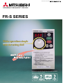
FR-S SERIES
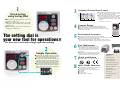
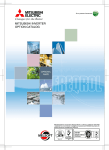
Make operations simple
with the setting dial!
Mitsubishi Electric Corporation Nagoya Works is a factory certified for ISO14001
(standards for environmental management systems) and ISO9001(standards for
quality assurance managememt systems)
Quick Setting
using Setting Dial
)
3
Automatic Torque Boost Control
% 300
Load torque(
1
200
100
0
●The frequency and parameters etc. can be set
with a few simple steps.
●Easily set values: turn quickly to greatly
change the value, and turn slowly to finely adjust the value.
●Accurate settings can be made with the new
notch-type "clicking" feel.
180 300
900
1800
Rotation speed(r/min)
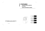
●By incorporating Mitsubishi's original and newly
developed "automatic torque boost control", a maximum 150% torque at 6Hz is possible.
●The need for torque boost setting can be eliminated
and the current during no load can be controlled.
Example speed-torque characteristics using newly
developed automatic torque boost control is shown
on the left.
(For SF-JR 4P 0.75kW motor)
The setting dial is
your new tool for operations!!
5
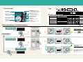
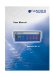
●The foot print is the same as the Mitsubishi FREQROL-E520.
●(400V class installation area has been unified to 108mm(128m.)
●The height dimensions for all capacities have been unified to 128mm,
making panel layout easier.
Environment Awareness
128mm
4
Compact Design
68mm
●The popular Soft-PWM control is incorporated as standard.
An increase in noise can be reduced, and noise can be suppressed to a minimum.
●Reactor connection to aid harmonic suppression.
The compact and lightweight DC reactor (FR-BEL) can be connected.
Connect an AC reactor (FR-BAL) when using the single-phase 100V class.
See how easy it is to make simple operation settings.
2
6
Simple Operation
PUSH
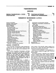
●As the default, the parameters that can be set have
been grouped into the minimum required twelve parameters. Thus, parameters can be managed easily.
●The modes can be changed between the PU and external operation modes just by pressing the PU/EXT (operation mode changeover) key. The current operation
mode can be confirmed with the status display LED.
●The set frequency and the output current value can be
monitored just by using the setting dial (set frequency
monitor) or SET key (output current value monitor).
(When in the monitor display state.)
Example of PU operation mode
7
8
Easy Maintenance
●The cooling fan can be replaced easily due to a
simple cassette design. By setting the fan "ONOFF control", operation with an extended life
can be realized. (The ON-OFF control is set as
the default.)
●Wiring space is secured and the wiring work efficiency is enhanced by incorporating an expanded front cover and comb-type wiring cover.
Global specification
●Compatible with UL, cUL and EN (CE Mark).
Other Handy Functions
●Terminal function (multi-speed 15 of speeds, error
reset, output stop, etc.) can be selected
●In-rush current suppression circuit is standard for
all capacities
●PID control
●4 to 20mA input
●Sink/Source logic is selectable
CONTENTS
Control panel
…………………………………2
Model Configuration
…………………………………3
General Specifications
…………………………………4
Common Specifications
…………………………………4
Extermal Dimension Drawings
…………………………………5
Terminal connection diagram
…………………………………5
Explanation of Terminals
…………………………………5
List of Parameters
…………………………………6
Explanation of Parameters
…………………………………7
Alarm Displays
…………………………………8
Selecting Peripheral Devices
…………………………………8
List of Options
…………………………………8
Precautions
…………………………………9
1
Quick Setting
using Setting Dial
)
3
Automatic Torque Boost Control
% 300
Load torque(
1
200
100
0
●The frequency and parameters etc. can be set
with a few simple steps.
●Easily set values: turn quickly to greatly
change the value, and turn slowly to finely adjust the value.
●Accurate settings can be made with the new
notch-type "clicking" feel.
180 300
900
1800
Rotation speed(r/min)
●By incorporating Mitsubishi's original and newly
developed "automatic torque boost control", a maximum 150% torque at 6Hz is possible.
●The need for torque boost setting can be eliminated
and the current during no load can be controlled.
Example speed-torque characteristics using newly
developed automatic torque boost control is shown
on the left.
(For SF-JR 4P 0.75kW motor)
The setting dial is
your new tool for operations!!
5
●The foot print is the same as the Mitsubishi FREQROL-E520.
●(400V class installation area has been unified to 108mm(128m.)
●The height dimensions for all capacities have been unified to 128mm,
making panel layout easier.
Environment Awareness
128mm
4
Compact Design
68mm
●The popular Soft-PWM control is incorporated as standard.
An increase in noise can be reduced, and noise can be suppressed to a minimum.
●Reactor connection to aid harmonic suppression.
The compact and lightweight DC reactor (FR-BEL) can be connected.
Connect an AC reactor (FR-BAL) when using the single-phase 100V class.
See how easy it is to make simple operation settings.
2
6
Simple Operation
PUSH
●As the default, the parameters that can be set have
been grouped into the minimum required twelve parameters. Thus, parameters can be managed easily.
●The modes can be changed between the PU and external operation modes just by pressing the PU/EXT (operation mode changeover) key. The current operation
mode can be confirmed with the status display LED.
●The set frequency and the output current value can be
monitored just by using the setting dial (set frequency
monitor) or SET key (output current value monitor).
(When in the monitor display state.)
Example of PU operation mode
7
8
Easy Maintenance
●The cooling fan can be replaced easily due to a
simple cassette design. By setting the fan "ONOFF control", operation with an extended life
can be realized. (The ON-OFF control is set as
the default.)
●Wiring space is secured and the wiring work efficiency is enhanced by incorporating an expanded front cover and comb-type wiring cover.
Global specification
●Compatible with UL, cUL and EN (CE Mark).
Other Handy Functions
●Terminal function (multi-speed 15 of speeds, error
reset, output stop, etc.) can be selected
●In-rush current suppression circuit is standard for
all capacities
●PID control
●4 to 20mA input
●Sink/Source logic is selectable
CONTENTS
Control panel
…………………………………2
Model Configuration
…………………………………3
General Specifications
…………………………………4
Common Specifications
…………………………………4
Extermal Dimension Drawings
…………………………………5
Terminal connection diagram
…………………………………5
Explanation of Terminals
…………………………………5
List of Parameters
…………………………………6
Explanation of Parameters
…………………………………7
Alarm Displays
…………………………………8
Selecting Peripheral Devices
…………………………………8
List of Options
…………………………………8
Precautions
…………………………………9
1
Control panel
Type
FR
S52 0
0.1K
PU/EXT key:
RUN display
Shows the operation state.
RUN key:Forward run
3-digit LED monitor
(Can be changed to reverse run
with parameter settings.)
Shows the parameter number
and setting value.
Symbol
1
2
4
Power specifications
Changes the setting mode.
3-phase 400V
Sets the frequency, and
changes the parameter setting.
0.1K
Single-phase input
Single-phase input
(double voltage output)
3.7K
SET key:
Single-phase 200V
(Note)
Sets the frequency setting and
parameter setting.
Single-phase 100V
(Note)
Basic operations (At default setting)
0.1K
0.2K
0.4K
RESET
RUN
RESET
EXT
SE
Return to the monitor and
frequency setting.
0.75K
1.5K
PU
MODE
SET
[Example] Changing
the parameter setting
Parameter setting
The desired frequency setting will appear.
1
2
Press the PU/EXT key to display PU.
RESET
EXT
Remarks
: No correspondence
MODE
SET
Starts when
RUN
is pressed.
Stops when
STOP
RESET
is pressed.
PU
PU
EXT
Press the SET key within
5s after turning the dial.
3
RU
RUN
PU
3.7K
EX
MOD
Turn the setting dial.
2.2K
F and frequency flicker
STOP
RESET
Press the MODE key.
(IP40)
Writing of the frequency
setting is completed!
RU
PU
EXT
RUN
MODE
RS-485 function provided
Totally enclosed structure
: Available model,
Press the PU/EXT key to display PU.
PU
Structure, communication
function, etc.
Enclosed type
Inverter capacity
Inverter type
[Example] Operating with
the control panel
(Screen at power ON)
This screen appears.
None
R
C
Indicates capacity
(kW)
(Note) The output is 3-phase 200V.
Monitor and
frequency setting
Symbol
Inverter capacity
FR -S 52 0 -ⵧ K
F R -S5 2 0-ⵧK- R
F R -S5 2 0-ⵧK- C
F R -S5 4 0-ⵧK
F R -S5 4 0-ⵧK- R
F R -S5 2 0S -ⵧK
F R -S5 2 0S -ⵧK - R
F R -S5 1 0W-ⵧ K
F R -S5 1 0W-ⵧ K-R
3-phase 200V
MODE key:
Setting dial
Symbol
3-phase input
(The inverter capacity is shown in the box)
Stop/reset (at alarm)
Shows operation mode.
None
S
W
No. of power supply
phases, etc.
Model Configuration
STOP/RESET key:
PU display/EXT display
Symbol
Voltage
100V class
200V class
400V class
~
Changes the operation mode.
PU=Control panel operation mode
EXT=External operation mode
MODE
SET
EX
MOD
RUN
MODE
SE
STOP
RESET
Press the MODE key.
MODE
Turn the setting dial.
The parameter No. will
appear.
Press the SET key after turning the dial.
The currently set number will be read out.
SET
3
Setting of the parameters
is completed!
Parameter No. and changed value flicker
Alarm history
RESET
Note: If the parameters are set in the external operation mode (When only EXT
is lit), Er2 (error) may appear depending on the parameter.
4
5
Turn the setting dial, and set the number of the
next parameter to be changed.
6
RU
PU
MODE
SET
EX
●Press the MODE key once to return to the
Alarm History screen.
●Press the MODE key twice to return to the
Monitor and Frequency Setting screen.
MOD
MODE
SE
Turn the setting dial.
Press the MODE key.
2
The desired setting value
will appear.
After reading and changing the setting:
Press the SET key after
turning the dial.
3
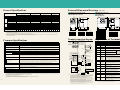
External Dimension Drawings (Unit: mm)
Single-phase 100V
FR-S540-ⵧⵧ
FR-S520-ⵧⵧ
FR-S520S-ⵧⵧ
FR-S510W-ⵧⵧ
Type
0.1K
0.2K
0.4K 0.75K 1.5K
2.2K
3.7K
0.4K 0.75K 1.5K
2.2K
3.7K
0.1K
0.2K
0.4K 0.75K 1.5K
0.1K
0.2K
0.4K 0.75K
Applicable motor capacity (kW) (Note 1)
0.1
0.2
0.4
0.75
1.5
2.2
3.7
0.4
0.75
1.5
2.2
3.7
0.1
0.2
0.4
0.75
1.5
0.1
0.2
0.4
0.75
Rated capacity (kVA)(Note 2)
0.3
0.5
1.0
1.6
2.8
4.0
6.6
0.9
1.6
2.7
3.7
5.9
0.3
0.5
1.0
1.6
2.8
0.3
0.5
1.0
1.6
Rated current (A)
0.8
1.4
2.5
4.1
7.0
10
16.5
1.1
2.1
3.5
4.8
7.7
0.8
1.4
2.5
4.1
7.0
0.8
1.4
2.5
4.1
䊏FR-S520-0.1K, 0.2K, 0.4K, 0.75K
䊏FR-S520S-0.1K, 0.2K, 0.4K, 0.75K
䊏FR-S510W-0.1K, 0.2K, 0.4K
䊏FR-S520-1.5K, 2.2K, 3.7K
䊏FR-S540-0.4K, 0.75 K, 1.5K, 2.2K, 3.7K
䊏FR-S520S-1.5K
䊏FR-S510W-0.75K
5 hole
5 hole
5
Single-phase 200V
RUN
RUN
Output
EXT
RUN
RUN
150% for 60 s, 200% for 0.5 s (Inverse time characteristics)
Rated input AC voltage/frequency
3-phase 200 to 240V, 50/60 Hz
3-phase 380V to 480V, 50/60 Hz Single-phase 200 to 240V, 50/60Hz Single-phase 100V to115V, 50/60Hz
Tolerable AC voltage fluctuation
170 to 264V, 50/60Hz
3-phase 200V to 230V, 50/60Hz
MODE
MODE
SET
Within 5%
9
1.5
2.5
4.5
5.5
9.5
0.5
Cooling method
Self-cooling
Approximately weight (kg)
0.5
0.5
0.8
Forced cooling
0.9
1.5
1.5
2.1
0.9
1.5
2.5
4.4
0.5
0.9
1.5
2.5
Enclosed type (IP20)
Self-cooling
1.5
1.5
Forced cooling
1.5
1.6
1.7
Forced cooling
Self-cooling
0.5
0.6
0.8
1.0
5
5.5
1.5
0.6
0.7
0.9
6
56
68
1.6
6
18.5
D2
6
D1
Select from V/F control (Soft-PWM control/high carrier frequency PWM control selective) and automatic torque boost control
Output frequency range
0.5 to 120Hz (starting frequency can be varied between 0 and 60Hz)
Frequency setting resolution
D1 D2
Capacity
0.1/0.2K
80.5 10 52
0.1K
80.5 10 52
0.4K
112.5 42 52
0.4K
142.5 42 82
0.2K
110.5 10 82
0.75K
132.5 62 52
0.75K
162.5 62 82
0.4K
142.5 42 82
150% (at 6Hz) during automatic torque boost control
Acceleration/deceleration time setting
0,0.1 to 999 s (acceleration/deceleration can be set individually), linear or S-pattern acceleration/deceleration mode can be selected
Regenerative (Note 1)
0.1K, 0.2K, 150%, 0.4K, 0.75K, 100%, 1.5K, 50%, 2.2K 3.7K 20%
DC braking
Operation frequency (0 to 120Hz), operation time (0 to 10 seconds), operation voltage (0 to 15%)
MC
Input signals
Output signals
Operation functions
Operation functions
Upper/lower limit frequency setting, frequency jump operation, external thermal input selection, restart after instantaneous power failure,
forward/reverse run prevention, slip compensation, operation mode selection, PID control, computer link operation (RS-485) (Note 5)
One type of open collector output can be selected from inverter running (RUN), frequency reached (SU), frequency detection (FU), overload
warning (OL), zero current detection (Y13), output current detection (Y12), PID upper limit (FUP), PID lower limit (FDN), PID forward/
reverse run (RL), READY (RY), minor failure (LF), and error (A, B, C). One type can be selected for the contact output (1 contact, 230VAC 0.3A, 30VDC 0.3A).
AC power
supply
NFB
MC
3-phase AC
power supply
Protection and warning functions
Ambient temperature and humidity
–10˚C to +50˚C(non freezing), (–10˚C to + 40˚C for fully enclosed structure specifications), 90%RH or less(non condensing)
Storage temperature (Note 3)
–10˚C to +65˚C
Atmosphere
Indoors with no corrosive gases, flammable gases, oil mist or dust
Altitude and vibration
1000m or less above sea level, 5.9m/s2 or less (JIS C 0040 compliant)
(Notes) 1. The indicated braking toque is the short-term average torque (which changes with motor loss) when the motor alone is decelerated from 60Hz. It is not the continuous regenerative torque. Deceleration
from frequencies exceeding the base frequency will have a lower average deceleration torque value.
2. If an undervotlage occurs, an error will not be output, but the output will be cutoff. Operation can be resumed after restoring the power, but depending on the operation state (size of load, etc.), the overcurrent protection or regenerative overvoltage protection may function when the power is restored.
3. This is the temperature to which units can be exposed for a short time, such as during transportation.
4. This corresponds only to the products with built-in cooling fan.
5. This applies only to the type with RS-485 function.
6. This functions only when the external thermal input (OH) is selected with Pr. 60 to Pr. 63 (input terminal function selection).
7. This functions only when Pr. 40 (start-time ground fault detection selection) is set to 1.
D1 D2 D3
170 158 142.5 72 52 5
3.7K
3-phase 400V power supply
Capacity W W1
D
D1 D2 D3
U
Motor
S
V
IM
T
W
(Note 7) P1
P
External transistor common
PC
Forward run start
Reverse run start
Multi-speed selection
(high speed)
Multi-speed selection
(medium speed)
Multi-speed selection
(low speed)
RH (Note 8)
(Note 9) B
C
RM (Note 8)
(Note 9) RUN
RL (Note 8)
SD
SE
SD
Current input(–)
DC4~20mA(+)
Error output
(Relay output)
{
Operation
status output
(open collector output)
)
5(Common)
Variable coil type
1mA full-scale
Main circuit terminal
Control circuit input terminal
Control circuit output terminal
4(4~20mA)
(Note 5)
(Note 3)
PU connector
(RS-485)
Grounding
(Notes) 1. This is not required when calibrating with the setting dial. Use this when calibrating
the frequency meter manually because the frequency meter is at a remote location etc.
Note that when the scale calibration resistor is connected, the needle on the frequency
meter may not adjust to the full scale. In this case, calibrate with the setting dial.
2. If the setting unit is used frequently, use the 2W1k potentiometer.
3. This is provided only with the type having the RS-485 function.
4. This is a connection example for when the control circuit logic is sink (default setting).
5. When using the current input for the frequency setting signal, set one of the parameters
between Pr. 60 and Pr. 63 (terminal function selection) to 4, and assign one of the terminals RH, RM, RL or STR to AU (current input selection).
6. This cannot be mounted on the single-phase 100V power input specification product.
7. The single-phase 100V power input specification product does not have terminals.
8. The RL, RM, RH, RT, AU, STOP, MRS, OH, REX, JOG, RES, X14 and X16 signals
can be selected with the input terminal function selection (Pr. 60 to 63).
9. The RUN, SU, OL, FU, RY, Y12, Y13, FDN, FUP, RL, LF, and ABC signals can be
selected with the output terminal function selection (Pr. 64, 65).
Wiring hole
Cooling fan*
Single-phase 200V power supply
Capacity W W1
1.5K
D
D1 D2 D3
108 96 155.5 65 72 8
Single-phase 100V power supply
Capacity W W1
D
D1 D2 D3
108 96 149.5 59 72 5
0.75K
*The FR-S510W-0.75K FR-S540-0.4K,0.75K does not have a cooling fan.
Terminal name
Detailed explanation
Connect to the commercial power supply.
Power supply input
U, V, W
Inverter output
Connect to the 3-phase squirrel cage motor.
DC voltage common
This is the DC voltage common terminal. It is not insulated from the power supply and inverter output.
Power factor
improvement
DC reactor connection
Remove the short-circuit bar between terminals P and P1 and connect the optional power factor
improvement DC reactor (FR-BEL). (This cannot be connected with the FR-S510WK(-R).)
Grounding
This is for grounding the inverter chassis. Always ground the inverter.
Forward run start
This functions as the forward run command when the STF signal is ON,
and the stop command when the signal is OFF.
N
P, P1
This functions as the reverse run command If the STF and STR signals turn ON simultaneously, these will function as the stop comwhen the STR signal is ON, and the stop
mand.The terminal function will change accordcommand when the signal is OFF.
ing to the input terminal selection (Pr. 60 to Pr.
The multi-speed type can be selected
63) Refer to the input signals in the common
specifications on page 4 for details on the terby
combining
the
terminal
RH,
RM
and
RL
RH, RM, RL Multi-speed selection
minal functions that can be changed.
signal short circuits.
10(+5V)
2 0~5V
0~10V
D1
R, S, T
Reverse run start
SD
Contact input
common (sink)
This is the common terminal for the contact input
(terminals STF, STR, RH, RM, RL) and meter connection (terminal FM).
Terminal 5 and terminal SE are insulated.
PC
External transistor
common 24VDC
power supply
contact input
common (source)
When connecting a transistor output (open collector output) such as
a programmable controller (PLC), malfunctioning caused by the supplied
current can be prevented by connecting the external power supply common
for the transistor output to this terminal.This can be used as the 24VDC 0.1A
power supply between terminals PC and SD. When the source logic is
selected, this will be the common terminal for the contact input signal.
10
Frequency setting
power supply
5VDC. Tolerable load current 10mA.
2
Frequency setting
(voltage signal)
When 0 to 5VDC (0 to 10V) is input, the maximum output frequency will be
reached at 5V (10V), and the input/output will be proportional.
Change between 5V and 10V with Pr. 73.
The input resistance is 10k, and the maximum tolerable input voltage is 20V.
5
Frequency setting
input common
This is the common terminal for the frequency setting signal (terminal 2, 4).
This is insulated from terminal SD and terminal SE.
Do not ground this common.
4
Frequency setting
(current signal)
Input 4 to 20mA DC.The default setting is adjusted to 0Hz at 4mA and
60Hz at 20mA.The maximum tolerable input current is 30mA,
and the input resistance is appoximately 250.
Error output
(relay output)
1 relay output which indicates that the inverter protective function
has activated and the output has stopped. 230VAC 0.3A 30VDC
0.3A. When there is an error, there is non-continuity between B-C
(continuity between A-C), and during normal operation, there is
continuity between B-C (non-continuity between A-C).
Inverter running
The L level is output when the inverter output frequency is higher than the
starting frequency (0.5Hz default can be changed). The H level is output when
stopped or during DC braking (Note 1). The tolerable load is 24VDC 0.1A.
FM
Frequency setting signal
(
108 96 165.5 65 82 8
STR
DC reactor FR-BEL (Note 6)
for power factor
improvement
(Option: refer to page 8.)
Scale calibration resistor
(Note 1)
Frequency meter
SOURCE
(Note 2) (3)
Frequency (2)
potentiometer
1/2W1k (1)
108 96 155.5 65 72 8
3.7K
STF
{
D2
Explanation of Terminals
N
(Note 9) A
108 96 135.5 65 52 8
2.2K
Ground
Short-circuit bar
STF
STR (Note 8)
1.5K
Terminal symbol
R
One type can be selected from output frequency or motor current. Pulse train output (1440 pulse/s 1mA full scale).
Overcurrent cutoff (during acceleration, deceleration, and constant speed), regenerative overvoltage cutoff (during acceleration,
deceleration, and constant speed), overload cutoff (electronic thermal relay), fin overheating, fan trouble (Note 4), stall prevention,
output side ground fault protection at starting (Note 7), external thermal input (Note 6), PU dislocation (Note 5), No. of retries exceeded,
communication error (Note 5), CPU error, undervoltage (Note 2)
D
1.5/2.2K 108 96 135.5 65 52 8
D1 D2
S
Inverter FREQROL-S500
SINK
For meter
D
Inverter FREQROL-S500
R
Control input signal (Note 4)
Frequency setting signal (0 to 5 (10)VDC), 4 to 20mA, digital setting with setting dial, start signal, error reset (RES), multi-speed selection
(RL, RM, RH, REX), 2nd function selection (RT), output stop (MRS), current input selection (AU), external thermal input (OH), start selfhold selection (STOP), JOG mode selection (JOG), PID action selection (X14), PU operation/external operation changeover (X16)
Capacity
{
Control specifications
Starting torque
D1 D2
Terminal connection diagram
NFB
18.5
D
0.4/0.75K 108 96 129.5 59 52 5
Analog input: Within 1% of maximum output frequency (25˚C 10˚C)
Digital input: Within 0.5% of set output frequency (when setting dial is used)
Frequency precision
Environment
5VDC input: 1/500 of maximum setting frequency, 10VDC, DC4 to 20mA input: 1/1000 of maximum setting frequency
Digital input: 0.1Hz (less than 100Hz), 1Hz (100Hz or more)
D
Capacity W W1
Single-phase 100V power supply
80.5 10 52
Single-phase
Control method
Single-phase 200V power supply
0.1/0.2K
D
6
3-phase 200V power supply
{
Common Specifications
3-phase 200V power supply
Capacity
W1
W
D
Wiring hole
(Notes) 1. The applicable motor indicates the maximum applicable capacity when using a Mitsubishi standard 4-pole motor.
2. The rated output capacity is 230V for the 3-phase 200V output voltage, and 440V for the 3-phase 400V output voltage.
3. The overload current rating percentage indicates the percentage in respect to the inverter's rated output current. When used repeatedly, it is necessary to wait for the inverter motor to return to a temperature
less than the temperature for the 100% load.
4. The maximum output voltage will not exceed the power supply voltage for the 3-phase 200V/400V power input specification product and the single-phase 200V power input specification product. The
single-phase 100V power input specification product cannot output more than twice the power voltage.
5. The power capacity will change according to the power side impedance (including the input reactor or wire) values.
6. For the single-phase 100V power input specification product, when a load is applied on the motor, the output voltage will drop by approx. 10 to 15%. However, when using a general-purpose motor, the
load must be reduced before use.
D3
5
4
5
Self-cooling
Main circuit
4.0
Control circuit (input signal)
2.1
Control circuit (output signal)
1.2
Communication
0.7
Enclosed type (IP20) (Fully enclosed structure series is IP40)
5
Power facility capacity(kVA)(Note 5) 0.4
Braking torque
SET
90V to 132V, 50/60Hz
170 to 264V, 50/60Hz
325V to 528V, 50/60Hz
Tolerable frequency fluctuation
Protective structure (JEM 1030)
3-phase 200 to 240V, 50/60 Hz
118
3-phase 380V to 480V, 50/60 Hz
128
3-phase 200 to 240V, 50/60 Hz
Power supply
STOP
RESET
STOP
RESET
Voltage (Note 4)(Note 6)
118
Overload current rating (Note 3)
4
PU
EXT
PU
PU
EXT
PU
EXT
128
3-phase 400V
3-phase 200V
Specifications
5
General Specifications
A, B, C
RUN
The terminal function
will change according
to the output terminal
function selection
(Pr.64,65). Refer to the
output signals in the
common specifications
on page 4 for details on
the terminal functions
that can be changed.
SE
Open collector common This is the common terminal for the terminal RUN. This is insulated from terminal 5 and terminal SD.
FM
Display connection
The inverter is set so that the terminals FM to SD will output approximately
1mA at 60Hz (default value). The output frequency is proportional. The output voltage is a pulse waveform, so a digital display can be connected.
Pulse specifications: 1440 pulses/s at 60Hz.
—
RS-485 connector
(Note 2)
Communication with RS-485 is possible.
•Standard compliance: EIA Standards RS-485
•Transmission format: Multidrop link method
•Communication speed: Max. 19200 baud, •Total length: 500m
The parameter unit FR-PU04 can be connected using the parameter unit
connection cable FR-CB201 to 205.
(Notes) 1. The L level refers to when the open collector output transistor is ON (continuity state). The H level
refers to when the transistor is OFF (non-continuity state).
2. This is provided only with the type having the RS-485 function.
5
List of Parameters
Explanation of Parameters
䊏Basic functions <default state>
Pr.0 Torque boost
Setting range
Default setting
Minimum setting unit
0
Torque boost
0~15%
0.1%
6%/5%/4% (Note 4)
1
Maximum frequency
0~120Hz
0.1Hz
60Hz
2
Minimum frequency
0~120Hz
0.1Hz
0Hz
3
Base frequency
0~120Hz
0.1Hz
60Hz
4
Multi-speed setting (high speed)
0~120Hz
0.1Hz
60Hz
5
Multi-speed setting (medium speed)
0~120Hz
0.1Hz
30Hz
6
Multi-speed setting (low speed)
0~120Hz
0.1Hz
10Hz
7
Acceleration time
0~999 s
0.1 s
5s
8
Deceleration time
0~999 s
0.1 s
5s
9
Electronic thermal O/L relay
0~50A
0.1A
Rated output current (Note 3)
30
Extended function display selection
0, 1
1
0
79
Operation mode selection
0~4, 7, 8
1
0
100%
Pr.20
Setting
range
Output frequency
Base frequency
Pr.3
Acceleration time
Pr.7
12
DC injection brake voltage
13
Starting frequency
14
Load pattern selection
15
JOG frequency
16
JOG acceleration/deceleration time
17
RUN key rotation direction selection
19
Base frequency voltage
20
Acceleration/deceleration reference frequency
21
Stall prevention function selection
22
Stall prevention operation level
Stall prevention operation level
compensation factor at double speed
Zero current detection level
88
PID operation selection
51
Zero current detection time
89
PID proportional band
52
Control panel display data selection
90
PID integral time
53
Frequency setting operation selection
91
PID upper limit
54
FM terminal function selection
92
PID lower limit
55
Frequency monitor reference
93
PID control set point during PU operation
56
Current monitor reference
94
PID differential time
57
Restart coasting time
95
Motor rated slip
58
Restart cushion time
96
Slip compensation time constant
59
Remote setting function selection /
Frequency setting storage function selection
97
Constant output area slip compensation selection
60
RL terminal function selection
98
Automatic torque boost selection
(motor capacity)
61
RM terminal function selection
62
RH terminal function selection
63
STR terminal function selection
64
RUN terminal function selection
Can be selected with
the RL, RM, RH, RT,
AU, STOP, MRS, OH,
REX, JOG, RES, X14,
X16 and STR signals.
(The STR signal can
be assigned only
with Pr. 63.)
Can be selected with the
RUN, SU, OL, FU, RY,
Y12, Y13, FDN, FUP, RL,
LF and ABC signals.
PID control
DC injection brake operation time
99
Motor primary resistance
n1
Communication station number
n2
Communication speed
n3
Stop bit length
n4
Parity check presence/absence
n5
Number of communication retries
n6
Communication check time interval
n7
Wait time setting
n8
Operation command write
n9
Speed command write
n 10
Link start mode selection
n 11
CR/LF selection
n 12
E PROM write validity selection
25
Multi-speed setting (speed 5)
26
Multi-speed setting (speed 6)
65
A, B, C terminal function selection
27
Multi-speed setting (speed 7)
66
Retry selection
28
Stall prevention operation reduction starting frequency
67
Number of retries at alarm occurrence
29
Acceleration/deceleration pattern
68
Retry waiting time
31
Frequency jump 1A
69
Retry count display erase
32
Frequency jump 1B
70
Soft-PWM setting
33
Frequency jump 2A
71
Applicable motor
34
Frequency jump 2B
72
PWM frequency selection
35
Frequency jump 3A
73
0 to 5V/0 to 10V selection
36
Frequency jump 3B
74
Input filter time constant
n 13
PU display language
37
Speed display
75
Reset selection/ PU stop selection
n 14
PU buzzer sound control
38
Frequency setting voltage gain frequency
76
Cooling fan operation selection
n 15
PU contrast adjustment
39
Frequency setting current gain frequency
77
Parameter write disable selection
n 16
PU main display screen data selection
40
Start-time ground fault detection selection
78
Reverse rotation prevention selection
n 17
PU dislocation detection/PU setting lock
41
Up-to-frequency sensitivity
80
Multi-speed setting (speed 8)
c1
FM terminal calibration
42
Output frequency detection
81
Multi-speed setting (speed 9)
c2
Frequency setting voltage bias frequency
43
Output frequency detection at reverse rotation
82
Multi-speed setting (speed 10)
c3
Frequency setting voltage bias
44
2nd acceleration/deceleration time
83
Multi-speed setting (speed 11)
c4
Frequency setting voltage gain
84
Multi-speed setting (speed 12)
c5
Frequency setting current bias frequency
85
Multi-speed setting (speed 13)
c6
Frequency setting current bias
86
Multi-speed setting (speed 14)
c7
Frequency setting current gain
87
Multi-speed setting (speed 15)
2nd torque boost
47
2nd V/F (base frequency)
48
Output current detection level
49
Output current detection signal delay time
Calibration functions
46
Auxiliary
functions
2nd deceleration time
Communication/PU function (Note 2)
Multi-speed setting (speed 4)
Operation selection functions
24
45
Deceleration time
Pr.8
Name
Function Parameter
50
Slip
Automatic
torque boost compensation
11
Name
Function Parameter
Remote Restart
Display functions Current
setting
detection
DC injection brake operation frequency
Terminal function
selection
Name
10
Multi-speed operation functions
Standard operation functions
Current 2nd functions Output terminal
functions
detection
6
●For the acceleration time, set the time to reach
the acceleration/deceleration reference frequency
Pr. 20 (default value: 60Hz) from 0Hz,
and for the deceleration time, set the time to reach
0Hz from Pr. 20 (default value: 60Hz).
By setting parameter 30 to 1, the following extended function parameters can be set.
䊏Extended functions
23
●The motor torque in the low frequency area
can be adjusted according to the load.
Pr.0
(Notes) 1. The shaded parameters can be changed even during operation.
2. This parameter is provided only with the type having the RS-485 communication function.
3. This will be 85% of the rated output current for 0.75K or less.
4. This will be 5% for FR-S540-1.5K and 2.2K, and 4% for FR-S540-3.7K.
Function Parameter
Pr.7 Pr.8 Acceleration/deceleration time
Output frequency
Name
Output voltage
Basic functions
Parameter
Pr.1 Pr.2 Maximum/minimum frequency
●The upper limit and lower limit of the output
frequency is clamped.
100%
Output frequency
Function
"Pr." is the abbreviation of parameter.
Maximum
frequency
Pr.1
Minimum
frequency
Pr.2
Frequency setting signal
5V
(10V)
(20mA)
Pr.3 Base frequency
●Set the base frequency (reference frequency for motor
rated torque) between 0 and 120Hz according to the motor.
2
Pr.4 Pr.5 Pr.6 Multi-speed setting
●Various speeds (RH, RM, RL) can be selected
just by changing the contact signal from an
external source.
●Each speed (frequency) can be set
between 0 and 120Hz while the inverter is running.
Pr.9 Electronic thermal O/L relay
●The setting value to protect the motor from
overheating can be set as a current value.
Normally, the motor rated current is set for 50Hz.
●When 0A is set, the motor protective function
will not activate. (The inverter output transistor's
protective function will activate.)
●When connecting multiple motors, set an external
thermal relay for each motor.
Pr.30 Extended function display selection
●Set this to display and set the extended function parameters.
Setting value
Details
0
Display only basic functions
1
Display all parameters
Pr.79 Operation mode selection
●The inverter operation modes include operation
with external signal and operation with the PU
(setting dial, touch keys). The mode can be fixed
to one mode, or two modes can be used together.
*Refer to the Instruction Manual for details.
Details
Setting value
0
Operation is possible by changing between PU
(setting dial, touch key) operation or external operation.
1
2
Operation is possible only with PU (setting dial, touch key) operation.
Only external operation is possible.
Operation frequency
Starting signal
3
Setting with setting dial
· Multi-speed selection
· 4 to 20mADC input
External terminal (STF/STR)
Operation frequency
Starting signal
4
External terminal signal
(Multi-speed, 0 to 5VDC, etc.)
PU operation interlock
Operation mode external signal changeover
Select operation mode by turning PU operation/external operation
mode changeover (X16) signal ON and OFF.
c8
Parameter for manufacturer setting. Do not set.
7
CLr
Parameter clear
8
ECL
Alarm history clear
RUN key
7
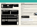
Alarm Displays
Overcurrent cutoff
Main LED Fault class
(Note 3)
display
Accelerating
Major fault
Constant speed
Major fault
Main LED Fault class
display
(Note 3)
Protective function name
Fan trouble
Overload
Minor fault
Communication error (Note 2)
Major fault
Major fault
CPU error
Major fault
Overcurrent
speed loss
Overvoltage
speed loss
—
Decelerating
Major fault
Accelerating
Major fault
Constant speed
Major fault
External thermal relay (Note 1)
Major fault
Decelerating
Major fault
PU disconnected (Note 2)
Major fault
Transistor
Overload cutoff
(electronic thermal
overcurrent protection) Motor
Major fault
Output side ground fault protection
(Note 5)
Major fault
Major fault
Retry count
Major fault
Fin overheat
Major fault
Parameter memory element error
Major fault
Regenerative
overvoltage cutoff
Stall prevention
Main LED Fault class
display
(Note 3)
Protective function name
—
Undervoltage (Note 4)
—
Parameter
setting
error
Write disable error
—
Write-while running error/
mode designation error
—
Calibration error
—
(Notes) 1. This functions only when the external thermal relay input (OH) is selected with Pr. 60 to Pr. 63 (input terminal function selection).
2. This applies only when the RS-485 communication function is provided.
3. Major fault : The protective function activates, inverter output is shut off, and an error output is provided.
Minor fault : Output is not shut off even when the protective function activates. It is possible to output minor fault signals by making parameter settings.
4. An error is not output when an undervoltage occurs, but the inverter output is cut off. The operation can be resumed after the power is recovered.
5. This activates only when Pr. 40 (ground fault detection at starting selection) is set to 1.
6. Refer to the instruction manual for details on PS and Err displays.
3-phase
200V
3-phase
400V
Motor
output
(kW)
No-fuse
(NFB)
Applicable inverter type breaker
Earth leakage
breaker (NV)
0.1
0.2
0.4
0.75
1.5
2.2
3.7
0.4
0.75
1.5
2.2
3.7
FR-S520-0.1K(-R,C)
FR-S520-0.2K(-R,C)
FR-S520-0.4K(-R,C)
FR-S520-0.75K(-R,C)
FR-S520-1.5K(-R,C)
FR-S520-2.2K(-R,C)
FR-S520-3.7K(-R,C)
FR-S540-0.4K(-R)
FR-S540-0.75K(-R)
FR-S540-1.5K(-R)
FR-S540-2.2K(-R)
FR-S540-3.7K(-R)
30AF 5A
30AF 5A
30AF 5A
30AF 10A
30AF 15A
30AF 20A
30AF 30A
30AF 5A
30AF 5A
30AF 10A
30AF 15A
30AF 20A
Magnetic
contactor
(MC)
S-N10
S-N10
S-N10
S-N10
S-N10
S-N11,S-N12
S-N20
S-N10
S-N10
S-N10
S-N20
S-N20
Wire (mm2)
(Note 1)
R,S,T
2
2
2
2
2
2
3.5
2
2
2
2
2
U,V,W
2
2
2
2
2
2
3.5
2
2
2
2
2
No-fuse
(NFB)
Applicable inverter type breaker
Earth leakage
breaker (NV)
R,S,T
U,V,W
0.1
FR-S520S-0.1K(-R)
30AF 5A
S-N10
2
2
0.2
FR-S520S-0.2K(-R)
30AF 10A
S-N10
2
2
0.4
FR-S520S-0.4K(-R)
30AF 10A
S-N20
2
2
0.75
FR-S520S-0.75K(-R)
30AF 15A
S-N20
2
2
1.5
FR-S520S-1.5K(-R)
30AF 20A
S-N21
2
2
0.1
FR-S510W-0.1K(-R)
30AF 10A
S-N10
2
2
0.2
FR-S510W-0.2K(-R)
30AF 15A
S-N10
2
2
0.4
FR-S510W-0.4K(-R)
30AF 20A
S-N20
2
2
0.75
FR-S510W-0.75K(-R)
30AF 30A
S-N20
3.5
2
Singlephase
200V
Singlephase
100V
Magnetic
contactor
(MC)
Type
FR-PU04
Stand alone type
Application and specifications, etc.
Interactive parameter unit with LCD display
Can be used only
FR-CB201(1m)
with FR-S5ⵧⵧ-ⵧK-R
Cable for connecting
FR-CB203(3m)
Cable for connecting parameter unit and inverter
type with RS-485
parameter unit
FR-CB205(5m)
communication function
Power factor improvement AC reactor FR-BAL(H)ⵧⵧ(Note 2)(Note 8) For power factor improvement (power factor approx. 90%)
Connect to input side
Power factor improvement DC reactor FR-BEL(H)ⵧⵧ(Note 2)(Note 6)(Note 8) For power factor improvement (power factor approx. 95%)
Radio noise filter
FR-BIF(H)(Note 8)
Reduces radio noise
Connect to input side
Line noise filter
FR-BSF01
Reduces line noise
Surge voltage suppression filter FR-ASF-Hⵧⵧ (Note 2) For micro-surge voltage suppression
BU type brake unit
Discharging resistor
BU(H)ⵧⵧ(Note 2)(Note 8) Greatly increases regenerative braking performance
High power factor converter
FR-HC-(H)7.5K(Note 8) For suppressing higher harmonics
Power regeneration common converter FR-CV-ⵧⵧ (-AT) (Note 2) (Note 9)
Dedicated standalone reactor FR-CVL-ⵧⵧ (Note 2)
EMC command compatible
noise filter (EU compatible)
FR series controllers and setters(Note1)
EMC filter installation attachment
8
GZG GRZG type
SF-ⵧⵧ(Note 3)
FR-S5NFSA-ⵧⵧ(Note 2)
FR-E5NF-Hⵧⵧ(Note 2)
FR-E5T
FR-UDA01
DIN rail installation attachment FR-UDA02
FR-UDA03
Operation box with frequency meter FR-AX
Sequential setting operation box FR-AL
3-speed setting operation box FR-AT
Remote operation box
FR-FK
Ratio setting box
FR-FH
PG follower
FR-FP
Master controller
FR-FG
Inclined signal box
FR-FC
Deviation detector
FR-FD
Pre-amplifier box
FR-FA
Pilot generator
QVAH-10
Deviation sensor
YVGC-500W-NS
Wire (mm2)
(Note 1)
Motor
output
(kW)
䊏Operation
●When a magnetic contactor (MC) is installed on the primary side, do not start and stop operation frequently with this MC.
Failure to observe this could lead to inverter faults.
●When a fault occurs in the inverter, the protective function will activate and the output will stop, but the motor will not stop
immediately. Thus, if the machine or facility requires emergency stop means, install mechanical stopping and holding
mechanism.
䊏Power supply
●If the unit is installed directly below a large-capacity power supply transformer (500kVA or more, with wiring length of 10m
or less), or where the phase advance capacitor switches, an excessive peak current may flow to the power input circuit causing
damage to the inverter. In this case, be sure to install the optional FR-BEL or FR-BAL power factor improvement reactor.
●If surge voltage is generated in the power system, this surge energy could flow into the
Power factor improvement
reactor installation range
inverter and cause the inverter to stop with the OV1, OV2 or OV3 alarm displayed. In this
1500
case, install the optional power factor improvement reactor FR-BEL or FR-BAL.
1000
(Note) 1. The wire size is for a wiring length of 20m.
List of Options
Name
Parameter unit (8 languages)
Power
voltage
●Always read the instruction manual before use to use the equipment properly and safely.
●This product is not designed or manufactured to be used in equipment or systems in situations that can affect or endanger
human life.
●When considering this product for operation in special applications such as equipment or systems used in passenger
transportation, medical, aerospace, nuclear energy, electric power, or submarine relay applications, please contact your nearest
Mitsubishi sales department.
●Although this product was manufactured under strict quality control conditions, it is strongly advised to install safety devices to
forestall serious accidents when used in facilities where a breakdown of the product is likely to cause a serious accident.
●Please do not use for loads other than 3-phase induction motors.
Cautions for Use
Selecting Peripheral Devices
Power
voltage
For Maximum Safety
Discharging resistor for BU type brake unit
Common converter type power regeneration brake unit
Reactor for power regeneration common converter
EMC Instruction (EN50081-2) compatible noise filter
* Measures must be taken to prevent malfunction of peripheral devices (earth leakage
breaker), etc., and electric shocks caused by leakage currents.
Attachment for installing EMC instruction compatible noise filter (SF1309) onto inverter
DIN rail installation
Applicable inverter
Type with
RS-485
communication
function
Compatible with 0.1K
to 3.7K capacities
Common for
all models
Compatible with FR-S5400.4K to 3.7K capacities
FR-S520-0.4K to 3.7K
FR-S540-2.2K to 3.7K
FR-S520-0.1K to 3.7K(Note 4)
FR-S540-0.4K to 3.7K(Note 4)
(Compatible with FR-S5200.1K to 3.7K capacities)
Compatible with FR-S520-0.1K
to 3.7K (Note 5), FR-S520S0.1K to 1.5K, FR-S510W-0.1K
to 0.75K (Note 7) capacities
FR-S540-0.4K to 3.7K
FR-S520-2.2K/3.7K
Compatible
with capacities
For independent operation with frequency meter, frequency setting unit and start switch
For sequential operation (1VA) with external signals (0 to 5VDC, 0 to 10VDC)
For operation changing between high, medium and low speed (1.5VA)
For remote operation; operation from several places is possible (5VA)
For ratio operation; ratios for up to five inverters can be set.
Common for
For follow-up operation using the signal of a pilot generator (PG). (2VA)
all models
Main speed setting unit for parallel operation of several inverters (up to 35 units). (5V)
For soft starting/stopping; parallel operation acceleration/deceleration is possible (3VA)
For synchronous operation. Used with deviation sensor and synchro. (5VA)
Can be used as A/V converter or operation amplifier (3VA)
70/35VAC 500Hz for tracking operation (at 2500r/min)
For synchronous operation (mechanical deviation detection). Output 90VAC/90˚
(Notes) 1. Rated power consumption for the FR Series operation and setting box power supply specifications are 200VAC 50Hz, 200/220V 60Hz, 115VAC 60Hz.
2. The values given in boxes indicate the capacity.
3. ⵧⵧ indicates a value.
4. One 3.7K inverter must be connected. (When using without the 3.7K inverter connected, use as a common converter or regenerative converter is possible, but the power higher harmonic suppression effect will drop.)
5. The EMC filter installation attachment (FR-E5T) must be used when installing SF filter on the FR-S520-2.2K/3.7K.
6. This cannot be mounted on the single-phase 100V power input specification product.
7. A 0.75K filter capacity is used for the 0.4K or less inverter capacity, and a 1.5K filter capacity is used for the 0.75K inverter capacity.
8. The 3-phase 400V input specification product is indicated with an "H" in the type.
9. -AT indicates the type installed in the panel. If -AT is not added, this is an external cooling fin type. Note that either method can be used for the 37K and 55K types by changing the position of the installation legs, so -AT is not added.
䊏Wiring distance
●If the wiring is long, the charging current caused by the suspended capacity of the wiring may
cause the fast response current limit function to activate. Make sure that the maximum wiring
length is less than the values in the table below.
Inverter capacity
During non- 100V class
200V class
low noise
operation
400V class
During low- 100V class
noise
200V class
operation
400V class
0.1K
0.2K
0.4K
0.75K
1.5K
2.2K
Power facility capacity
(kVA)
Protective function name
Precautions
500
0
Wiring length (m)
10
3.7K
100m 100m 100m 100m 100m 100m 100m
–
–
30m
30m
–
–
50m
100m 100m 100m 100m
100m 100m 100m 100m 100m
30m
30m
100m 100m 100m
●When automatic torque boost is selected, make sure that the length of the wiring between the inverter and motor is 30m or
less.
䊏Grounding
●When the inverter is run with low-noise, the leakage current will increase because of the
high-speed switching compared to the non-low noise operation. Always ground the
inverter and motor. Always use the inverter's grounding terminal to ground the inverter.
●For 400V class, make save to ground the supply nevtral.
䊏Noise
When carrying out low-noise operation with the carrier frequency increased, the magnetic noise will tend to increase. Refer to
the following countermeasures, and act accordingly. Depending on the installation state, the effect of noise may be apparent even
during non-low noise operation (default state).
The radio noise filter FR-BIF is effective against static noise heard in AM radio broadcasts.
䊏Leakage current
Electrostatic capacitance occurs between the inverter's input/output wiring, other wiring, grounding and motor. The leakage
current can flow through these and cause the earth leakage breaker, leakage relay and external thermal to operate unnecessarily.
Take measures by lowering the Pr. 72 carrier frequency, using harmonics and surge compatible parts for the earth leakage
breaker, and using an electronic thermal O/L relay built into the inverter.
9
Safety Warning
To ensure proper use of the products listed in this catalog,
please be sure to read the instruction manual prior to use.
MITSUBISHI ELECTRIC CORPORATION
HEAD OFFICE : MITSUBISHI DENKI BLDG., 2-2-3, MARUNOUCHI, CHIYODA-KU, TOKYO 100-8310, JAPAN
L(NA)06017-B(0105)MDOC