1
2D Code Handy Scanner
AT27Q-SB
User's Manual
Copyright © DENSO WAVE INCORPORATED, 2013
All rights reserved. No part of this publication may be reproduced in any form or by any means without permission in
writing from the publisher.
All products and company names mentioned in this manual are trademarks or registered trademarks of their respective
holders.
QR code, SQRC and QBdirect are trademaks of DENSO WAVE INCORPORATED. Microsoft Windows is a
trademark of Microsoft Corporation. Bluetooth is a trademark of Bluetooth SIG. Other products and company names
mentioned in this document are trademarks or registered trademarks of their respective holders.
Specifications are subject to change without prior notice.
Contents
Preface..........................................................................................................................................................................................i
Customer Registration and Inquiries ...........................................................................................................................................i
SAFETY PRECAUTIONS.........................................................................................................................................................ii
Components Required...............................................................................................................................................................vii
Bluetooth® Wireless Communication Link ............................................................................................................................ viii
Care and Maintenance................................................................................................................................................................ix
Chapter 1
Names and Functions ..............................................................................................................................................1
Chapter 2
Bluetooth Interface................................................................................................................................................2
2.1 Enabling Bluetooth Interface ...............................................................................................................................2
2.2 Establishing Bluetooth Wireless Link .................................................................................................................3
2.3 Breaking Bluetooth Wireless Links.....................................................................................................................6
2.4 Reestablishing Bluetooth Wireless Links............................................................................................................6
2.5 Indication of Bluetooth Wireless Link Status......................................................................................................7
Chapter 3
Reading Codes ......................................................................................................................................................8
3.1 Before Use..............................................................................................................................................................8
3.2 Operation Procedure...............................................................................................................................................8
Chapter 4
Customizing the Scanner ......................................................................................................................................10
Chapter 5
Scanning Control...................................................................................................................................................11
5.1 Trigger Switch Control ........................................................................................................................................11
5.2 Software Control ..................................................................................................................................................12
5.3 Auto Sensing Mode--Automatic detection of labels ...........................................................................................12
Chapter 6
Scanning Functions...............................................................................................................................................13
6.1 Data Verification Mode........................................................................................................................................13
6.1.1 Data verification read procedure...............................................................................................................13
6.1.2 Specifying a verification object ................................................................................................................15
6.1.3 Verification result output ..........................................................................................................................16
6.2 Editing Data..........................................................................................................................................................17
6.2.1 Data extraction mode ................................................................................................................................17
6.2.1.1 Extracting a data string..........................................................................................................................17
6.2.1.2 Extracting data blocks ...........................................................................................................................19
6.2.1.3 Extracting AI (Application Identifier)-prefixed strings........................................................................21
6.2.2 Data substitution mode .............................................................................................................................29
6.2.3 Data blocksorting mode ............................................................................................................................30
6.2.4 ADF script mode.......................................................................................................................................31
6.3 Point Scan Mode ..................................................................................................................................................32
6.4 Scanning a Mirror Image 2D Code ......................................................................................................................32
6.5 Scanning a Black-and-white Inverted Code ........................................................................................................32
6.6 Scanning Structured Appended QR (iQR) Code Symbols ..................................................................................33
6.7 Multi-line Barcode Scanning ...............................................................................................................................34
6.7.1 Number of lines.........................................................................................................................................34
6.7.2 Data output order ......................................................................................................................................34
6.7.3 Output format............................................................................................................................................34
6.8 Scanning an SQRC (Security QR Code) Symbol ................................................................................................34
Chapter 7
Beeper, Indicator LED, Marker Beam, and Illumination LEDs...........................................................................35
7.1 Beeper...................................................................................................................................................................35
7.2 Indicator LED.......................................................................................................................................................37
7.3 Marker Beam........................................................................................................................................................39
7.4 Illumination LEDs................................................................................................................................................39
Chapter 8
Communication .....................................................................................................................................................40
8.1 Bluetooth Interface.............................................................................................................................................40
8.2 HID Profile ...........................................................................................................................................................41
8.3 Communication Format........................................................................................................................................42
8.4 GTIN Format Conversion ....................................................................................................................................56
8.5
Chapter 9
Data Packaging (Packetizing)..............................................................................................................................61
Charging and Replacing the Battery Cartridge.....................................................................................................64
9.1 Charging the Battery Cartridge ............................................................................................................................64
9.2 Replacing the Battery Cartridge...........................................................................................................................66
9.3 Recycling the Battery Cartridge...........................................................................................................................68
Chapter 10
Image Capturing..................................................................................................................................................69
10.1 Outline ..................................................................................................................................................................69
10.2 Image Capturing Specifications ...........................................................................................................................69
Chapter 11
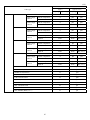
Parameters and Defaults......................................................................................................................................72
Chapter 12
QR-Coded Parameter Menu................................................................................................................................91
12.1 Customizing the Scanner with the QR-Coded Parameter Menu .........................................................................91
12.2 QR-coded Parameter Menu..................................................................................................................................92
Chapter 13
QR-Coded Parameter Menu for Communications Adapters
(BA11/10-RKU) ............................................102
13.1 Customizing the Communications Adapter from the Scanner ..........................................................................102
13.2 QR-Coded Parameter Menu for Communications Adapters .............................................................................104
Chapter 14
Troubleshooting ................................................................................................................................................108
Appendix 1
Specifications...................................................................................................................................................109
Appendix 2
Control Commands ..........................................................................................................................................110
Appendix 3
Bluetooth Glossary ........................................................................................................................................113
Preface
Thank you for using the AT27Q DENSO WAVE 2D code Handy Scanner.
Please READ through this manual carefully. It will enable you to operate your scanner correctly.
After you have finished reading this manual, keep it handy for speedy reference.
Note: Do not use this scanner in an environment with electrical noise that can trigger malfunction.
Note: Specifications described in this manual are supported by AT27Q Firmware version 1.00 or later.
DENSO WAVE INCORPORATED does not assume any product liability arising out of, or in connection with, the
application or use of any product, circuit, or application described herein.
If it is judged by DENSO WAVE INCORPORATED that malfunction of the product is due to the product having
been dropped or subjected to impact, repairs will be made at a reasonable charge even within the warranty period.
Intellectual Property Precaution
DENSO WAVE INCORPORATED (“DENSO WAVE”) takes reasonable precautions to ensure its products do not
infringe upon any patent of other intellectual property rights of other(s), but DENSO WAVE cannot be responsible for
any patent or other intellectual property right infringement(s) or violation(s) which arise from (i) the use of DENSO
WAVE’s product(s) in connection or in combination with other component(s), product(s), data processing system(s)
or equipment or software not supplied from DENSO WAVE; (ii) the use of DENSO WAVE’s products in a manner
for which the same were not intended nor designed; or (iii) any modification of DENSO WAVE’s products by other(s)
than DENSO WAVE.
Limited Warranty on Software Products
In no event will DENSO WAVE be liable for direct, indirect, special, incidental, or consequential damages (including
imaginary profits or damages resulting from interruption of operation or loss of business information) resulting from
any defect in the software or its documentation or resulting from inability to apply the software or its documentation.
Customer Registration and Inquiries
Customer Registration
To allow us to provide our customers with comprehensive service and support, we request that all customers complete
a Member Registration Form. Registered members will be offered the following privileges.
Latest upgrade information
Free exhibition and event information for new products
Free web-information service “QBdirect”
QBdirect Service Contents
Information search service
(FAQ)
Offers detailed information on each product.
Download service
Offers downloads of repair modules for the latest AT27Q Series systems or software,
and sample programs.
E-mail inquiries
Allows customers to send product-related queries by e-mail.
Please note that these privileges may be subject to change without prior notice.
How to Register
Access the URL below and follow the instructions provided.
http://www.qbdirect.net
i
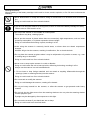
SAFETY PRECAUTIONS
Be sure to observe all these safety precautions.
Please READ through these instructions carefully. They will enable you to use the scanner correctly.
Always keep this manual nearby for speedy reference.
Strict observance of these warnings and cautions is a MUST for preventing accidents that could result in bodily injury
and substantial property damage. Make sure you fully understand all definitions of these terms and symbols given
below before you proceed to the text itself.
Alerts you to those conditions that could cause serious bodily injury or death if the
instructions are not followed correctly.
Alerts you to those conditions that could cause minor bodily injury or substantial property
damage if the instructions are not followed correctly.
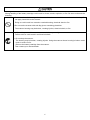
Meaning of Symbols
A triangle ( ) with a picture inside alerts you to a warning of danger. Here you see the warning for
electrical shock.
A diagonal line through a circle ( ) warns you of something you should not do; it may or may not have a
picture inside. Here you see a screwdriver inside the circle, meaning that you should not disassemble.
A black circle ( ) with a picture inside alerts you to something you MUST do. This example shows that
you MUST unplug the power cord.
ii
To System Designers:
When introducing the scanner in those systems that could affect human lives (e.g., medicines
management system), develop applications carefully through redundancy and safety design
which avoids the feasibility of affecting human lives even if a data error occurs.
Handling the battery cartridge
Wrong handling of the battery cartridge could result in a heat, smoke, explosion, or fire. Be sure to observe the
following.
Never disassemble or heat the battery cartridge, nor put it into fire or water; doing so could
cause battery-rupture or leakage of battery fluid, resulting in a fire or bodily injury.
Do not carry or store the battery cartridge together with metallic ballpoint pens, necklaces,
coins, hairpins, etc.
Doing so could short-circuit the terminal pins, causing the batteries to rupture or the battery fluid
to leak, resulting in a fire or bodily injury.
Never put the battery cartridge into a microwave oven or high-pressure container.
Doing so could cause the batteries to break, generate heat, rupture or burn.
Avoid dropping the battery cartridge or letting it undergo any shock or impact.
Doing so could cause the batteries to break, generate heat, rupture or burn.
Never charge the battery cartridge where any inflammable gases may be emitted; doing so
could cause fire.
If any abnormality is detected--smoking, abnormal odors, discoloration or deformation when the
battery cartridge is in use, in storage or being charged, remove the battery cartridge from the
scanner or charger.
Only use the dedicated charger for charging the battery cartridge.
Using a different type of charger could cause battery-rupture or leakage of battery fluid and
result in a fire, bodily injury, or serious damage to property.
The battery cartridge contains strong alkaline liquid (electrolyte).
If battery liquid leaks from the battery cartridge and it gets into your eyes, rinse them with clean
water thoroughly without rubbing and consult a doctor as soon as possible. Otherwise, you may
damage your eyes.
iii
Handling the scanner
Wrong handling of the battery cartridge could result in a heat, smoke, explosion, or fire. Be sure to
observe the following
The scanner uses a laser light for indicating
the scanning range. The intensity of laser
light might be too low to inflict bodily injury.
However, do not stare into beam.
The scanner complies with IEC 60825-1
Ed.2:2007.
In accordance with Clause 5 and 6, IEC
60825-1, the following information is provided
to the user:
LASER LIGHT
DO NOT STARE INTO BEAM
CLASS 2 LASER PRODUCT
Caution – Use of controls or adjustments or performance of procedures other than those
specified herein may result in hazardous laser light exposure.
If smoke, abnormal odors or noises come from the scanner, immediately remove the battery
cartridge and contact your nearest dealer.
Failure to do so could cause fire or electrical shock.
If foreign material or water gets into the scanner, immediately remove the battery cartridge and
contact your nearest dealer.
Failure to do so could cause fire or electrical shock.
If you drop the scanner so as to affect the operation or damage its housing, remove the battery
cartridge and contact your nearest dealer.
Failure to do so could cause fire or electrical shock.
Do not use the scanner where any inflammable gases may be emitted.
Doing so could cause fire.
Do not subject the scanning window of the scanner to direct sunlight for extended periods.
Doing so could damage the scanner, resulting in a fire.
Never bring any metals into contact with the terminals in connectors.
Doing so could produce a large current through the scanner, resulting in heat or fire, as well as
damage to the scanner.
Stop charging if it cannot be completed within the specified time.
Never put the scanner into a microwave oven or high-pressure container.
Doing so could cause the batteries to break, generate heat, rupture or burn.
Never use the scanner on the line voltage other than the specified level.
Doing so could cause the charger to break or burn.
Use the dedicated battery cartridge only.
Failure to do so could result in fire.
iv
Handling the scanner
Wrong handling of the battery cartridge could result in a heat, smoke, explosion, or fire. Be sure to observe the
following
Never disassemble or modify the scanner; doing so could result in an accident such as break or
fire.
Never
disassemble
Doing so could result in a fire or electrical shock.
If you are not using the scanner for a long time, be sure to remove the battery cartridge for safety.
Failure to do so could result in a fire.
Do not put the scanner on an unstable or inclined plane.
The scanner may drop, creating injuries.
Never put the scanner in places where there are excessively high temperatures, such as inside
closed-up automobiles, or in places exposed to direct sunlight.
Doing so could affect the housing or parts, resulting in a fire.
Avoid using the scanner in extremely humid areas, or where there are drastic temperature
changes.
Moisture will get into the scanner, resulting in malfunction, fire or electrical shock.
Do not place the scanner anyplace where it may be subjected to oily smoke or steam, e.g., near
a cooking range or humidifier.
Doing so could result in a fire or electrical shock.
Never cover or wrap up the scanner in a cloth or blanket.
Doing so could cause the unit to heat up inside, deforming its housing, resulting in a fire.
Always use the scanner in a well-ventilated area.
Do not insert or drop foreign materials such as metals or anything inflammable through the
openings (vents or scanning window) into the scanner.
Doing so could result in a fire or electrical shock.
Do not scratch or modify the scanner.
Doing so could damage the scanner, creating a fire hazard.
Do not put heavy material on the scanner, or allow the scanner to get pressed under heavy
material.
Do not look into the light source from the scanning window or do not point the scanning window
at other people's eyes.
Eyesight may be damaged by direct exposure to this light.
Do not use the scanner if your hands are wet or damp.
Doing so could result in an electrical shock.
v
Handling the scanner
Wrong handling of the battery cartridge could result in a heat, smoke, explosion, or fire. Be sure to observe the
following
Never use chemicals or organic solvents such as benzene and thinner to clean the housing. Do
not apply insecticide to the scanner.
Doing so could result in a marred or cracked housing, electrical shock or fire.
Do not use the scanner with anti-slip gloves containing plasticizer.
The scanner housing may be broken, creating injuries, electrical shock, or fire.
When taking care of the scanner, remove the battery cartridge.
Failure to do so could result in an electrical shock.
Do not drop the scanner.
The housing may be broken, creating injuries. Using the scanner whose housing is broken could
result in smoke or fire.
Remove the battery cartridge from the scanner.
Then contact your nearest dealer.
vi
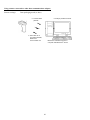
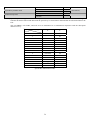
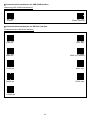
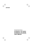
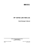
Components Required
The scanner (AT27Q-SB) requires the following components that differ depending upon whether the communications
adapter is used and which interface is selected.
When using the communications adapter (BA11/10-RKU)
Basic components
The table below lists the basic components required for the use of the communications adapter.
(1) Scanner
AT27Q-SB
(2) Communications adapter
BA11/10-RKU
(3) Charger
CH-AT10L
(4) AC adapter
AD2-1005/3000
For charger
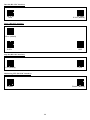
Components required for individual interfaces
For RS-232C interface
(5) RS-232C interface cable
CBBA-RS2000/9
(6) AC adapter
AD2-1005/3000
For communications adapter
For RS-232C interface and communications adapter mounted in the charger
(5) RS-232C interface cable,
Charger built-in type
CBBA-RS2000/9-1
For USB keyboard or USB-COM interface
(5) USB interface cable
CBBA-US2000/4
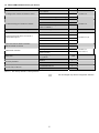
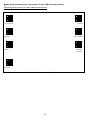
When directly communicating with Bluetooth-enabled equipment
(no BA11/10-RKU communications adapter is used)
(1) Scanner
AT27Q-SB
(2) Charger
CH-AT10L
(3) AC adapter
AD2-1005/3000
Bluetooth
interface
Scanner
(AT27Q-SB)
Bluetooth
interface
Communications
adapter
(BA11/10-RKU)
Bluetooth-enabled
computer
Charger
(CH-AT10L)
AC adapter
(AD2-1005/3000)
vii
For charger
USB keyboard interface
USB-COM keyboard interface
RS-232C keyboard interface
Host computer
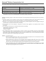
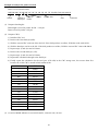
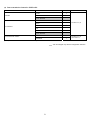
Bluetooth® Wireless Communication Link
The scanner AT27Q-SB uses Bluetooth® wireless networking technology.
Item
Specifications
®
Standard
Bluetooth Specification Ver. 2.1+EDR
Radio output
Class 2 (maximum 2.5 mW)
Profile(s) supported
SPP (Serial Port Profile), HID (Human Interface Device Profile)
Communications range (reference value*1)
Max. 10 m, with no obstructions
*1 This value is for wireless networking between the scanner and the BA11/10-RKU communications adapter. The
communications range varies with the equipment used and the operating environment.
Wireless networking requires a stable radio environment. Not all operating environments provide this. In particular,
note that
Using the scanner in close proximity to other wireless LAN equipment operating in the same frequency band (2.4
GHz) risks radio interference that can reduce throughput or even entirely block wireless networking.
Microwave ovens, industrial heating equipment, high-frequency medical equipment, and other equipment using the
2.4 GHz band can sometimes block wireless networking.
Electromagnetic noise from computers, refrigerators, and other home appliances can sometimes block wireless
networking.
The following environments can sometimes block wireless networking.
- Metal objects or particles in the vicinity
- Metal walls around the area
- Excessive vibration
The communications range of 10 m given above is merely a reference value assuming a clear line of sight. Reliable
wireless networking is by no means guaranteed at 10 m for all combinations of equipment used and operating
environments. Some combinations might even work for greater distances, but be sure to confirm that the scanner
link operates properly before introducing the link operation.
NOTE: To System Designers:
Before developing applications, make sure that the intended environment is free of the interference factors
above and thus actually capable of supporting link operation.
When introducing the scanner into an environment where equipment using radio waves in the 2.4 GHz
band operates or when introducing such equipment after the introduction of the scanner, be sure to confirm
that the scanner radio link operates properly with all equipment being in operation beforehand.
If the environment of the radio communications system is changed after the introduction (e.g., newly
installed household appliances and movement/addition of shelves or objects), then confirm that the radio
link operates properly again before the actual use.
viii
Care and Maintenance
■ Proper Care of the reading window
Dust or dirt accumulating on the clear plate of the code reading window will affect reading performance. If you use
the scanner in dusty areas, therefore, periodically check the clear plate and clean it if dusty.
To clean the plate, first blow the dust away with an airbrush. Then wipe the plate with a cotton swab or the similar
soft one gently.
If sand or hard particles have accumulated, never rub the plate; doing so will scratch or damage it. Blow the
particles away with an airbrush or a soft brush.
■ Proper Care of the Scanner body
Wipe any dirt from the Scanner body with a dry, soft cloth.
Note
• Never use substances such as benzene or alcohol, as this may cause the housing to be marred or paint to peel off.
• If excessively dirty, wipe a soft cloth that has been soaked in soapy water (always use neutral detergent) and wrung
out thoroughly.
ix
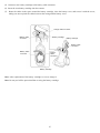
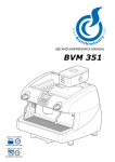
Chapter 1
Names and Functions
Built-in antenna
Bluetooth® antenna.
Do not modify this antenna
section or cover it by hand.
Indicator LED
Illuminates in blue when the scanner has read
a code successfully.
Refer to Section 7.2 for details.
If any error occurs, this LED flashes in red.
Reading window
Bring this window to a
code to be scanned.
Trigger switch
Press this switch to read data or
initiate a Bluetooth® wireless link.
The following read modes are
available to match the needs of
the intended application.
• Auto-off mode
• Momentary switching mode
• Momentary switching mode
(Reverse Type)
• Alternate switching mode
• Continuous reading mode 1
• Continuous reading mode 2
• Auto sensing mode
• Auto stand mode
(The factory default setting is
auto-off mode.)
Refer to Chapter 5 for details.
• The Bluetooth® wireless link is
disconnected by holding down
the trigger switch. (Bluetooth®
wireless link disconnection is
set to enable when shipped
from the factory.)
Beep hole
The beeper sounds when the
scanner has read a code
successfully.
Battery cover
Remove this cover to replace
the battery cartridge.
1
Chapter 2
Bluetooth Interface
For terms relating to Bluetooth wireless communication in this manual, refer to Appendix 3 "Bluetooth Glossary."
2.1
Enabling Bluetooth Interface
Using the scanner for the first time requires scanning the "Start setting" and "Start operation" QR Code symbols given
in Section 12.2 with the procedure in Section 12.1. Using the scanner when the "End operation" is selected requires
scanning the "Start operation" QR Code symbol. Scanning those code symbols enables the Bluetooth interface.
Note: Always disable this scanner's Bluetooth interface in hospitals, aircraft, and other environments where the
Bluetooth radio waves (2400 to 2483.5 MHz, maximum 2.5 mW) present a potential safety risk.
This scanner interprets the "End operation" QR Code symbol as a command to disable the Bluetooth interface.
Note: When the scanner leaves the factory or it has scanned the "End operation" QR Code(in Section 13.2), it no
longer reads codes except the "Start operation" QR code, the " batch-process" QR code, and the barcode on the
reverse side of the Communications adapter (BA11/10-RKU).
2
2.2
Establishing Bluetooth Wireless Link
After enabling the Bluetooth interface, establish a Bluetooth wireless link between the scanner and the
BA11/10-RKU communications adapter (or some other Bluetooth equipment) using the following procedures. Both
devices have slave as their default configuration.
The scanner can configure itself as both a slave (default) and master. To configure it as a slave, use the QR-coded
parameter menu or configuration software (ScannerSetting_2D)*; to configure it as a master, it is necessary to specify
the slave's Bluetooth address to the scanner.
Tip: In addition to "As a master" and "As a slave" parameters, the configuration software provides a choice of "No
slave/master configuration change" (see page 68) that prevents the Bluetooth wireless link from getting broken when
you change other parameters with the configuration software or batch-process QR Code symbols (see Chapter 4).
Scanner as Slave (default)
The scanner is a slave by default. This slave can establish a Bluetooth wireless link with the BA11/10-RKU
communications adapter (or some other Bluetooth equipment) as a master without special communication
procedures.
(1) If the scanner is currently a master, use the scanner to read the "Configure as slave" QR Code symbol given in
Section 12.2 using the procedure in Section 12.1 to switch it to slave operation.
(2) Wait for the scanner to beep three times, press the scanner's trigger switch, and wait approximately two minutes
(default) for the master device to connect to this slave.
(3) Configure the communications adapter (or some other Bluetooth equipment) as a master and specify the
scanner's Bluetooth address.
For the communications adapter, use the configuration software (BASetting). (For other Bluetooth equipment,
use the procedures set forth in the user's manual.)
(4) Wait for the communications adapter (or some other Bluetooth equipment) to establish a Bluetooth wireless
link with the scanner as a slave.
(5) Wait for the scanner to beep twice and the indicator LED to turn green (for 0.5 second), indicating a successful
connection.
Note: If the master device cannot discover the scanner available in the vicinity, set the longer inquiry time and let
the master device search it again.
Note: In response to the connection request from the master device, the scanner unconditionally connects to it. No
Bluetooth passkey is required to specify.
* The configuration software (ScannerSetting_2D) is available as free downloads from our website at
http://www.denso-wave.com/.
3
Scanner as Master
To configure the scanner as a master and the communications adapter (or some other Bluetooth equipment) as a slave,
follow the sample procedures given below and specify the slave's Bluetooth address to the scanner. The connection
ratio of the scanner and slave device should be 1:1.
Using the communications adapter (example)
(1) Use the scanner to read the bar code (communications adapter's Bluetooth address) on the back of the
communications adapter.
(2) Wait for the scanner to configure itself as a master and establish a Bluetooth wireless link with the
communications adapter.
(3) Wait for the scanner to beep twice and the indicator LED to turn green (for 0.5 second).
Using some other Bluetooth device (example)
(1) Confirm the device's Bluetooth address.
For the instructions on how to confirm, see the user's manual.
(2) With the configuration software (ScannerSetting_2D)*, generate a "Bluetooth address" code that specifies the
equipment's Bluetooth address to the scanner.
When using a commercially available code generator, generate it in the following format.
Code type
Data format
QR Code Model 1, 2
%% ADDRXXXXXXXXXXXX %%
CODE 128 Code Set A
ADDRXXXXXXXXXXXX
(Note) XXXXXXXXXXXX should be a Bluetooth address in hexadecimal.
Example: Bluetooth address 000AF1234567
ADDR000AF1234567
(3) Use the scanner to read the "Bluetooth address" code.
(4) Wait for the scanner as a master to establish a Bluetooth wireless link with the specified Bluetooth device.
(5) Wait for the scanner to beep twice and the indicator LED to turn green (for 0.5 second), indicating a successful
connection.
Note: The scanner does not check the Bluetooth passkey when connecting to the slave device. If the slave device is so
set up that it asks for the Bluetooth passkey, therefore, modify the slave's setting to unconditionally connect to the master
device, using the procedures set forth in the user's manual.
4
When connecting the scanner with an iPhone or iPad.
Follow the procedures below when connecting the scanner with an iPhone or iPad.
When using the operator’s guide (included with the scanner).
(1) Turn the connected device ON to switch on the Bluetooth® function.
(2) Set the scanner communication settings.
Allows the scanner to scan “iOS(iPhone,iPad)”QR Code at Easy connection setup, QR-coded Parameter Menu.
Wait for the scanner to beep three times to complete the settings.
(3) Press the trigger switch of the scanner and wait for the connected device to be connected.
(4) Select the scanner from the connected device list and connect it to the device. The scanner beeps twice if
successfully connected.
(5)
The next time connecting to the device, simply press the trigger switch.
When using the setting software (ScannerSetting_2D)
(1) Select the SPP profile for the scanner and connect it to the communication adapter (BA11-RKU) or the host
computer equipped with the Bluetooth®.
(2) Change the scanner settings to “HID” for the interface, “SSP” for the security function, “Slave” for the mode,
“Peripheral keyboard” for the local device ID of the setting software (ScannerSetting_2D).
(3) Select the scanner from the connected device list and connect it to the device. The scanner beeps twice if
successfully connected.
(4)
The next time connecting to the device, repeat the step (3).
5
2.3
Breaking Bluetooth Wireless Links
Holding down the trigger switch for 5 seconds or scanning the "Break Bluetooth wireless link" QR Code symbol
forcibly breaks the scanner's Bluetooth wireless link. (The QR Code symbol is given in Section 12.2 and its
procedure in Section 12.1.)
Note: Breaking the Bluetooth wireless link does not disable the Bluetooth interface. To disable it, scan the "End
operation" QR Code symbol.
2.4
Reestablishing Bluetooth Wireless Links
When the scanner's Bluetooth wireless link has been broken by any of the following events, pressing the trigger
switch reestablishes the Bluetooth wireless link. The scanner as a slave waits for a connection request from the
master; the scanner as a master connects to a target slave.
-
Scanning the "Break Bluetooth wireless link" QR Code symbol (See Sections 12.1 and 12.2.)
Holding down the trigger switch to break the Bluetooth wireless link
Modifying the scanner configuration with the configuration software (ScannerSetting_2D)
"Reconnect request" dialog displayed by the configuration software (ScannerSetting_2D)
Replacing the battery cartridge
6
2.5
Indication of Bluetooth Wireless Link Status
The scanner's indicator LED and beeper together indicate the status of the scanner's Bluetooth wireless link.
When the trigger switch is held down:
Indicator LED
Beeper
Scanner Status
Silent
Reading is not possible when there is no Bluetooth wireless link
on enabling the link.
Red, flashing
Red, flashing twice repeatedly
The scanner has scanned the "End operation" QR Code symbol.
When the trigger switch is pressed and released:
Indicator LED
Beeper
Blue, flashing rapidly
Scanner Status
The scanner, as a master, is searching for a connection target.
Silent
Blue, flashing slowly
The scanner, as a slave, is waiting for a master to connect.
When the Bluetooth wireless link is established or broken:
Indicator LED
Beeper
Scanner Status
Green for 1 second
Two short beeps
The Bluetooth wireless link is ready for use.
Red for 1 second
Long beep
The Bluetooth wireless link no longer exists.
7
Chapter 3
Reading Codes
3.1 Before Use
Be sure to charge the battery cartridge loaded in the scanner with the dedicated charger before using the scanner for
the first time or after an extended period of disuse. (For the charging procedure, refer to Chapter 9.)
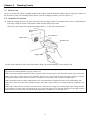
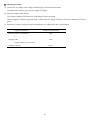
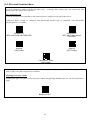
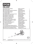
3.2 Operation Procedure
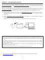
(1) Bring the reading window to a target code and press the trigger switch. The marker beam comes on, indicating the
scan range. Align the center of the marker beam with that of the target code.
(This step is not required for continuous reading modes 1, 2 and auto sensing mode.)
Effective Scan
range
Scan distance
Marker beam
Indicator LED
Trigger switch
(2) Wait for the indicator LED to turn blue and the beeper to sound, indicating a successfully read.
Note: The actual scan range is narrower than the marker range. The scan range is approx. 6cm (2.4") wide by 4cm (1.6")
high when the scanning distance is approx. 10cm (3.9").
Note: The marker range should only be used as a guide. It does not assure that a code within the marker range can be read.
Note: Allow only a single code to come within the field of view except when the multi-line code scanning is allowed.
Having more than one code within the field of view either causes the read to fail or produces multiple input.
Note: The double-read prevention enabled time can be specified with the configuration software (ScannerSetting_2D).
Note: The scanner can read codes omnidirectionally. Note that a target code plus its margin should lie within the scan
range.
Note: If the scanner fails to read due to specular effects or other factors, change the scanning angle of the reading window
or the distance from the codes, and repeat the process. (Specular effects occur when the reflection of the light from the
label surface is too strong, such as when the reflecting surface is polished or covered with vinyl.)
8
Scanning mode
Regular read mode
This mode transfers the code data when the scanner has read the code successfully.
Data verification mode
This mode verifies the code data against the master data stored in the scanner.
(Refer to Section 6.1 for details.)
Switching to sleep mode for power saving
The scanner switches from standby to sleep mode to save power when the trigger switch is off in the auto-off or
momentary switching mode or when the scanner is on standby in the alternate switching mode. (The scanner does not
switch to the sleep mode in the continuous reading mode 1 or 2 or in the auto sensing mode.)
The transition period from standby to sleep mode is 30 seconds in the ordinary current mode. In the power saving
mode (default), the scanner immediately switches to sleep mode. Only the configuration software
(ScannerSetting_2D) provides a choice of these two modes.
The scanner in sleep mode takes more time (approx. 100 ms) to start and complete a sequence of scanning operation
than the one on standby.
Auto power-off
If the scanner remains unused for the specified timeout period, it automatically shuts itself down. The timeout period
can be specified within the range from 5 to 640 minutes in 5-minute increments by using the configuration software
(ScannerSetting_2D). The configuration software can also disable this auto power-off feature.
®
Scanning with Bluetooth wireless link broken
The scanner can read codes even with the Bluetooth® wireless link being broken. Use this scanning way when
scanning codes is required but data transfer is not, for instance, when the scanner itself checks the verification result
without transferring it to the host computer.
Scanning with Bluetooth® wireless link broken and that with Bluetooth® wireless link established can be switched
only with the QR-coded parameter menu.
"Scan w/ Bluetooth link broken"
QR Code symbol
Allows the scanner to scan codes with the Bluetooth® wireless link
being broken. Scanning the QR Code symbol also disables the
Bluetooth® interface, making data transfer with the host computer
impossible.
Cancel "Scan w/ Bluetooth link broken"
QR Code symbol
Cancels the "Scan w/ Bluetooth® link broken" setting.
Scanning the QR Code symbol allows the scanner to scan codes
with the Bluetooth® wireless link being established. It also enables
the Bluetooth® interface, making data transfer with the host
computer possible.
Note: The "Scan w/ Bluetooth® link broken" parameter retains its setting even the scanner reads the "End operation" and
"Start operation" QR Code symbols in this order with the "Scan w/ Bluetooth® link broken" being selected. To cancel the
setting, you need to scan the "Cancel "Scan w/ Bluetooth link broken" QR Code symbol.
9
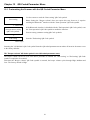
Chapter 4
Customizing the Scanner
You can customize the scanner by modifying communications, code type, and other scanner parameters with the
QR-coded parameter menu or the configuration software ScannerSetting_2D*. These parameters retain their settings
even when the power is off.
TIP: The scanner can hold not only its own parameter settings but also communications adapter parameter settings in
its memory and customize the communications adapter via the Bluetooth wireless link. There are two types of
bar-coded parameter menus available for scanners (Section 12.2) and communications adapters (Section 13.2).
(1) Scanning parameter setting QR Code symbols in the QR-coded parameter menu by pressing the trigger switch.
(The QR-coded parameter menus for scanners and communications adapters are given in Chapters 12 and 13,
respectively.)
(2) Using the configuration software (ScannerSetting_2D) in your computer. It is recommended that the scanner be
configured as a master.
(This software also offers batch-process QR Code symbols for ready by scanners in the field.)
Note: Customizing the scanner with the configuration software or batch-process QR Code symbols breaks the Bluetooth
wireless link, so it is necessary to establish the link again after customizing. To prevent the Bluetooth wireless link from
getting broken, select the "No slave/master configuration change" parameter for the item "Configure the scanner as master
or slave."
Note: When the "End operation" parameter is selected with the scanner, no parameter setting is possible. Prior to starting
parameter setting, therefore, be sure to scan the "Start operation" QR Code symbol. See Chapter 2 for the "Start
operation" and "End operation."
Note: When even the scanner is being charged, you can customize it with the configuration software except when the
"End operation" parameter is selected.
Note: The configuration software is not available via HID (Human Interface Device) Profile.
* The configuration software (ScannerSetting_2D) is available as free downloads from our website at
http://www.denso-wave.com/.
10
Chapter 5
Scanning Control
Two types of scanning controls are available--Trigger switch control and Software control.
Trigger switch control: Pressing the trigger switch readies the scanner for scanning. (Refer to Section 5.1.)
Software control: Instead of pressing the trigger switch, you send control commands from the host computer via the
Bluetooth® interface to ready the scanner for scanning or put the scanner on standby. (Refer to Section 5.2.) The
software control is not available via HID (Human Interface Device) Profile.
In addition, the auto sensing mode is also available. (Refer to Sections 5.3 and 5.4.)
5.1
Trigger Switch Control
Pressing the trigger switch turns on the illumination LEDs and readies the scanner for scanning. The scanner supports
the following six trigger switch operating modes. Select the one that best meets your needs using the QR-coded
parameter menu or the configuration software (ScannerSetting_2D).
(1) Auto-off mode
When the trigger switch is pressed, the scanner is brought to the Active state for approximately 5 seconds.
The scanner automatically returns to the Ready state when reading is successfully completed, or after approximately
five seconds elapsed with the trigger switch pressed.
The scanner goes to the Ready state if the trigger switch is released before five seconds elapses. (in the case of normal
mode)
When the Auto off mode is set to be active only once (One-shot mode), the time required for the scanner to become
the Ready state after the trigger switch was pressed shall be designated in the setting.
(2) Momentary switching mode
The scanner is brought to the Active state only when the trigger switch is pressed, and returns to the Ready state when
the trigger switch is released.
(3) Momentary switching mode (Reverse type)
The scanner is brought to the Ready state only when the trigger switch is pressed, and returns to the Active state when
the trigger switch is released.
(4) Alternate switching mode
The scanner alternates between the Active state and the Ready state every time the trigger switch is pressed.
(5) Continuous reading mode 1
Establishing the Bluetooth wireless link or selecting the "Scan w/ Bluetooth link broken" parameter, the scanner
lights the illumination LEDs and becomes ready to scan. The scanner ignores all trigger switch input.
If the scanner receives the Z, READOFF or LOFF command, it switches to standby; if it receives the R, READON or
LON command, it becomes ready to scan.
You can select whether or not the scanner transmits the ERROR command when the scanner cannot complete reading
and switches to standby, using the configuration software (ScannerSetting_2D).
(6) Continuous reading mode 2
This mode is functionally equivalent to the continuous reading mode 1, except that the scanner waits for a command
upon completion of scanning. To become ready to scan, the scanner should receive the Z, READOFF or LOFF
command to switch to standby and then receive the R, READON or LON command.
You can select whether or not the scanner transmits the ERROR command when the scanner cannot complete
scanning and switches to standby, using the configuration software (ScannerSetting_2D).
Note: When you are setting parameters using the QR-coded parameter menu, the scanner is always in the auto-off mode
regardless of the trigger switch operating mode selected.
Note: Establishing the Bluetooth wireless link or selecting the "Scan w/ Bluetooth link broken" parameter enables the
trigger switch control.
11
5.2
Software Control
You can control the scanner by sending scanning control commands from the host computer via the Bluetooth
interface, instead of pressing the trigger switch.
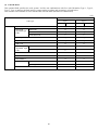
Scanning control commands include R, READON, LON, Z, READOFF and LOFF and are restricted by the trigger
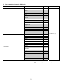
switch operating modes, as listed below.
( : Command valid)
Trigger switch operating modes
Commands
Description
R,
READON,
LON
Z,
READOFF,
LOFF
Auto-off
mode
Momentary
switching
mode
Momentary
switching mode
(Reverse type)
Alternate
Continuous
switching reading mode 1
mode
or 2
Ready-to-scan commands
Upon receipt of one of these
commands, the scanner lights
the illumination LEDs and
becomes ready to scan.
--
--
--
--
Standby commands
Upon receipt of one of these
commands, the scanner turns
off the illumination LEDs and
switches to standby.
--
--
--
--
Each of these commands should be enclosed with a header and terminator for transmission according to the
communications conditions of the scanner.
5.3
Auto Sensing Mode--Automatic detection of labels
After establishing the Bluetooth wireless link or selecting the "Scan w/ Bluetooth link broken" parameter, in the
Auto Sensing mode (Auto sense operation in Auto stand mode is included), bringing a code label within the scan
range of the reading window turns on the illumination LEDs and starts the scanner reading the code. No trigger switch
operation is required. Use this mode when the scanner is stationary to a stand and a code label is moved.
The illumination LEDs come on when you bring a code label within the designated range or move a code label within
the same range. These LEDs turn off when a code label is moved away from the range or stays within the range
without move for approx. 3 seconds.
In the Auto stand mode, after establishing the Bluetooth wireless link or selecting the "Scan w/ Bluetooth link
broken" parameter, the scanner is set to the Auto sense operation when the power is turned on.
If the trigger switch is pressed while the scanner is operating in this mode, the scanner goes to the Auto off and reads a
code whenever the trigger switch is pressed.
However, the scanner will automatically return to the Auto sense operation if the trigger switch is not pressed for
longer than a time specified for the scanner to return to the Auto sense.
The time for the scanner to return to the Auto sense operation from the Auto off operation can be selected with the
configuration software (ScannerSetting_2D).
Auto sensing mode and Auto stand mode are selected with the QR-coded parameter menu or the configuration software
(Scanner Setting_2D).
The scanner offers a choice of three sensitivity levels for responding to codes. Switch to a higher sensitivity level if
the illumination LEDs will not come on when a code is brought into the range, for example.
Note: Even if you do not bring a code label within the scan range, the illumination LEDs may come on when the ambient
level of light changes or any shadows move within the scan range.
Note: To enable the scanner to work properly in auto sensing mode, an ambient illuminance of at least 500 lx is required.
12
Chapter 6
6.1
Scanning Functions
Data Verification Mode
The data verification mode verifies the code data read against the master data stored in the scanner and reports the
match status with data output.
Data verification read is available in two types--"n-point verification" and "2-point verification," which can be
selected with the configuration software (ScannerSetting_2D).
Selecting the n-point verification requires registering master data only one time for 1:n verification. The scanner
verifies all code data read after registration against the master data.
The 2-point verification refers to 1:1 verification. Selecting it requires registering master data each time preceding
code scanning. After registration of master data, the scanner reads a code, verifies the code data read against the
master data and then becomes ready to register new master data. This way, the 2-point verification read alternately
repeats master data registration and code scanning.
In n-point verification read, master data can be registered with "preset master registration" or "scan master
registration"; in 2-point verification read, with "scan master registration" only. The preset master registration registers
master data with the configuration software (ScannerSetting_2D) beforehand, and the scan master registration, by
scanning a master code label.
The master data registered by "preset master registration" or "scan master registration" will be sent to the host
computer when you scan the "Output master data" code given on page 16.
The verification parameters can be specified with the configuration software (ScannerSetting_2D).
6.1.1 Data verification read procedure
n-point verification
Preset master registration
This is available only when n-point verification is selected. Register the code type and data to be used for verification
using the configuration software (ScannerSetting_2D). Up to 99 digits can be registered.
The registered master data will be preserved even if the scanner is turned off. To clear it, first clear the registered
master data stored in the host computer with the configuration software (ScannerSetting_2D) and then send the new
setting data to the scanner.
Scan master registration
1) Switch the scanner to the Data Verification mode.
2) Send a scan entry control command "E" from the host to the scanner. (Refer to Appendix 2 for control commands.)
The indicator LED lights in green.
3) Use the scanner to scan a master code to be registered. (The scanner operates in the trigger switch operating mode
currently set.) After registration of master data, the indicator LED turns blue and then goes OFF.
4) Use the scanner to scan a target code. The scanner verifies the code read against the master data registered and
then outputs the result. After a successful read, the indicator LED lights in blue.
During the registration operation above, if the master data has fewer characters than specified (e.g., less than the
specified verification start position), the registration operation aborts with an error.
Even if "Preset master registration" has been made, you can make "Scan master registration." If both have been made,
the number of characters to verify that has been specified with "Preset master registration" and the master data that has
been specified with "Scan master registration" will be valid.
Note: The registered master data will be cleared when you customize the scanner by modifying the parameters with
the configuration software (ScannerSetting_2D) or a batch-process QR code symbol.
Note: If no master data has been entered by either "Preset master registration" or "Scan master registration," the
indicator LED flashes in red, during which it is impossible to scan codes.
13
2-point verification
Scan master registration
1) Switch the scanner to the data verification mode. The indicator LED lights in green.
2) Use the scanner to scan a master code to be registered. (The scanner operates in the trigger switch operating mode
currently set.) After the registration of master data, the indicator LED turns blue and then goes OFF.
3) Use the scanner to scan a target code. The scanner verifies the code read against the master data registered and
then outputs the result.
After a successful read, the indicator LED lights in blue, indicating that the scanner is ready to register new master
data.
During the registration procedure above, if the master data has fewer characters than specified (e.g., less than the
specified verification start position), the registration operation aborts with an error. The scanner becomes ready to
register master data again.
Verification retry after mismatch in 2-point verification
The 2-point verification read provides the "Verification retry after mismatch" option that retries verification against
the same master data. Enabling this option with the configuration software (ScannerSetting_2D) readies the scanner
not for registering new master data but for reading a bar code again if the verification result is a mismatch.
Disabling this option readies the scanner for registering new master data after bar code reading, no matter what the
verification result is.
Note: Any of the following events clears the master data stored in the scanner.
- Turning the scanner power off.
- Modifying the verification start position or the number of characters to verify.
- Customizing the scanner by modifying the parameters with the configuration software (ScannerSetting_2D) or
by scanning a batch-process OR code symbol.
Note: The data verification area can be selected from "Code type + code data" or "Code data only" with the
configuration software (ScannerSetting_2D).
14
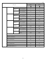
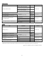
6.1.2 Specifying a verification object
You can specify two types of verification objects--data string and data block. For data string verification, specify the
verification start position and the number of characters to be verified. For data block verification, specify one of the
data blocks delimited by commas in the CSV format.
(1) Data string verification
The scanner verifies data specified by the verification start position and the number of characters to be verified against
the master data registered in the scanner, and then it outputs the verification result.
The verification start position should be within the range of 1 to 999, and the number of characters* to be verified,
within the range of 1 to 99.
*The number of characters for Code 39 and NW-7 symbols should be specified including start and stop codes.
In any of the following cases, the verification results in a mismatch:
1) The verification data in the specified position does not match the master data.
2) The code type which the verification data belongs to is different from the one which the master data belongs to.
See (Note) below.
3) All data specified is not included or no data is included within the specified range.
(Examples)
Master data
registered
Verification start
position
No. of characters
to be verified
Data string read
(Verification object)
Result
345
3
3
00345
Match
345
3
3
00345678
Match
345
3
3
00346
Mismatch
345
3
3
0034
Mismatch
(2) Data block verification
If data is saved in the comma-delimited CSV format, the scanner verifies data in the specified data block against the
master data registered in the scanner, and then outputs the verification result.
The data block position should be within the range of 1 to 99.
In any of the following cases, the verification results in a mismatch:
1) The verification data in the specified block does not match the master data.
2) The code type which the verification data belongs to is different from the one which the master data belongs to.
See (Note) below.
3) All data specified is not included or no data is included within the specified block.
4) The data block to be verified exceeds 99 characters in length.
(Examples)
Master data
registered
Position of data block
to be verified
345
3
0,12,345,6789
Match
345
3
0,12,346,6789
Mismatch
345
3
0,12,3456,6789
Mismatch
345
3
0,12,34,6789
Mismatch
345
3
0,12
Mismatch
Data block read
(Verification object)
Result
(Note) Whether the code ID mark is matched or not is determined not by the combination of code ID marks Type 1
and Type 2 but by Type 1 only (refer to Chapter 8, Section 8.2).
15
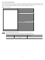
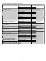
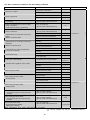
6.1.3 Verification result output
(1) Report of match/mismatch status
You can select any of the following report types using the configuration software (ScannerSetting_2D). Selecting
"Disable transmission" reports nothing.
If there is a match:
If there is a mismatch:
Disable transmission.
Disable transmission.
Code data transmission.
Code data transmission.
OK transmission.
NG transmission.
(2) Beeper and indicator LED
You can check whether the verification result is a match or mismatch with the beeper and indicator LED.
When the beeper and indicator LED are enabled, they act as shown below in default setting.
Beeper
Indicator LED
2-point
n-point
If there is a match:
Beeping times
Beeping tone
Emits a short 2 beeps.
Middle beeping tone
Lights in blue.
If there is a mismatch:
Emits a long beep.
High beeping tone
Flashes in red.
If there is a match:
Emits a short 1 beep.
Middle beeping tone
Lights in blue.
If there is a mismatch:
Emits a long beep.
Middle beeping tone
Flashes in red.
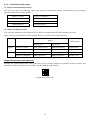
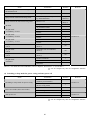
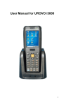
Output of the master data registered
Scanning the “Output master data” code given below lets the scanner output the verification section of master data
entered in the Data verification read procedure, together with the code ID mark.
“Output master data” code
16
6.2
Editing Data
You can edit and output code data read, in any of the four data edit modes--"data extraction mode," "data substitution
mode," "data blocksorting mode" and "ADF script mode." These data edit modes can be selected with the
configuration software (ScannerSetting_2D). The default is "No editing."
Note: In the case of multi-line bar codes, unless all code ID marks read are matched, the data editing processing will
result in an error regardless of whether or not the data read contains any error. Whether the code ID mark is matched is
determined not by the combination of code ID marks but by Type 1 only (refer to Chapter 8, Section 8.2).
Note: In the case of split QR Code, the scanner in edit mode or batch edit mode performs data editing processing upon
completion of scanning of all split code symbols; in non-edit mode, it performs each time a single split code symbol is
read.
6.2.1 Data extraction mode
This mode offers three extraction choices--"data string," "data block" and "AI (Application Identifier)-prefixed string"
extractions from code data read and then outputs it.
The "data block" extraction is available only when code data is in the comma-delimited CSV format. The "AI-prefixed
string" extraction is available for GS1-128 (EAN-128), GS1 DataBar (RSS), and EAN.UCC Composite symbols
(excluding linear components in a UPC/EAN Composite symbol).
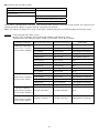
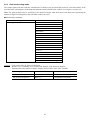
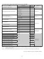
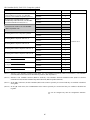
6.2.1.1 Extracting a data string
The scanner extracts a data string specified by the "Extraction start position" and "Extraction end position" from a
code specified by the "Code type" and then outputs it in the data transmission format selected in the scanner (see
Chapter 8, Section 8.2). The extraction conditions and extraction start and end positions are listed below.
Extraction conditions
Extraction conditions
"Code type"
"Data transfer regardless of error result"
Choices
Any code
QR Code
iQR Code
PDF417
Data Matrix
MaxiCode
Aztec
UPC-A/EAN-13
UPC-E
EAN-8
Code 128
GS1-128 (EAN-128)
Codabar (NW-7)
Code 39
Code 93
Interleaved 2of5 (ITF)
Standard 2of5 (STF)
GS1 DataBar (RSS)
EAN.UCC Composite symbology
Permit/Prohibit
If the scanner fails to extract a data string or scans a code not specified by "Code type" when the "Data transfer
regardless of error result" is permitted, then it outputs the data read as is without editing.
17
Extraction start and end positions
"Extraction start position"
Head position
"Extraction end position"
nth position
Tail position
nth position
Tail position
By n positions from the start position
nth position
The n can be 1 through 9999. Note that if the extraction start position is specified as nth position, the extraction end
position should be equal to or greater than the extraction start position.
Note: The number of characters for Code 39 and NW-7 symbols should be specified including start and stop codes.
Example Code read: QR Code, Data: 12345,
Header: STX, Terminator: ETX, Scanner ID: Disable, Code ID mark: Type 1,
Transmission of the number of digits: Enable, Prefix/Suffix: None, BCC: Disable
Extraction conditions
Extraction start position
Extraction end position
Output data
"Code type": QR Code
Head position
3rd position
[STX]Q0003123[ETX]
"Data transfer regardless
of error result": Prohibit
Tail position
3rd position
[STX]Q0003345[ETX]
1st position
Tail position
[STX]Q000512345[ETX]
1st position
By 3 positions
[STX]Q0003123[ETX]
2nd position
4th position
[STX]Q0003234[ETX]
Head position
6th position
Error
Tail position
6th position
Error
6th position
Tail position
Error
6th position
By 10 positions
Error
1st position
6th position
Error
"Code type": QR Code
Head position
6th position
[STX]Q000512345[ETX]
"Data transfer regardless
of error result": Permit
Tail position
6th position
[STX]Q000512345[ETX]
6th position
Tail position
[STX]Q000512345[ETX]
6th position
By 10 positions
[STX]Q000512345[ETX]
1st position
6th position
[STX]Q000512345[ETX]
Invalid if specified.
Invalid if specified.
Error
Invalid if specified.
Invalid if specified.
[STX]Q000512345[ETX]
"Code type": PDF417
"Data transfer regardless
of error result": Prohibit
"Code type": PDF417
"Data transfer regardless
of error result": Permit
18
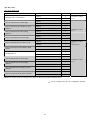
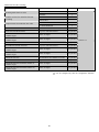
6.2.1.2 Extracting data blocks
If data read is in the comma-delimited CSV format, the scanner extracts data blocks specified by the data block
numbers from a code specified by the "Code type" and then outputs it in the data transmission format selected in the
scanner (see Chapter 8, Section 8.2). The extraction conditions and data bock numbers are listed below.
Extraction conditions
Extraction conditions
“Code type”
“Data transfer regardless of error result”
Choices
Any code
QR Code
iQR Code
PDF417
Data Matrix
MaxiCode
Aztec
UPC-A/EAN-13
UPC-E
EAN-8
Code 128
GS1-128 (EAN-128)
Codabar (NW-7)
Code 39
Code 93
Interleaved 2of5 (ITF)
Standard 2of5 (STF)
GS1 DataBar (RSS)
EAN.UCC Composite symbology
Permit/Prohibit
If the scanner fails to extract a data block or scans a code not specified by "Code type" when the "Data transfer
regardless of error result" is permitted, then it outputs the data read as is without editing.
Data block numbers
Each data block number should be within the range from 1 through 99. Up to three blocks can be extracted.
19
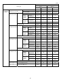
Example Code read: QR Code, Data: (See the table below.)
Header: STX, Terminator: ETX, Scanner ID: Disable, Code ID mark: Disable,
Transmission of the number of digits: Disable, Prefix/Suffix: None, BCC: Disable
Extraction conditions
Data read
Data block numbers
Output data
"Code type": QR Code 1,23,456,7890
1, 2 and 3
[STX]1[ETX][STX]23[ETX][STX]456[ETX]
"Data transfer
regardless of error
result": Prohibit
1,23,456,7890
3, 1 and 2
[STX]456[ETX][STX]1[ETX][STX]23[ETX]
1234567890
1
[STX]1234567890[ETX]
1,,23,456,7890
2 and 5
[STX][ETX][STX]7890[ETX]
1,23,456,7890
5
Error
1,23,456,7890
4 and 5
Error
1234567890
1 and 2
Error
"Code type": QR Code 1,23,456,7890
5
[STX]1,23,456,7890[ETX]
"Data transfer
regardless of error
result": Permit
1,23,456,7890
4 and 5
[STX]1,23,456,7890[ETX]
1234567890
1 and 2
[STX]1234567890[ETX]
1,23,456,7890
Invalid if specified. Error
1,23,456,7890
Invalid if specified. [STX]1,23,456,7890[ETX]
"Code type": PDF417
"Data transfer
regardless of error
result": Prohibit
"Code type": PDF417
"Data transfer
regardless of error
result": Permit
20
6.2.1.3 Extracting AI (Application Identifier)-prefixed strings
If the scanner reads any of GS1-128 (EAN-128), GS1 DataBar (RSS), and EAN.UCC Composite symbols (excluding
linear components in a UPC/EAN Composite symbol), it edits the data according to AIs and outputs it in the data
transmission format selected in the scanner (see Chapter 8, Section 8.2).
The "AI-prefixed string" extraction is available in two modes--AI-delimited mode and AI parenthesizing mode. AIs to
be used for data editing are listed in (3) AI table later.
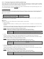
(1) AI-delimited mode
In this mode, the scanner extracts strings prefixed with AIs specified (up to three types of AIs) and separates them
with the specified delimiters (selectable from headers/terminators, commas and tabs) instead of AIs to output them.
Extraction conditions
Extraction conditions
"Data transfer regardless of error result"
Choices
Permit/Prohibit
If the scanner fails to extract an AI-prefixed string when the "Data transfer regardless of error result" is permitted, it
outputs the data read as is without editing.
Delimiters
Delimiters can be any of the following three--header/terminator, comma and tab.
Header/terminator
Specifying a header/terminator as delimiters prefixes a header and suffixes a terminator to each element string
separated.
A scanner ID, code ID mark, the number of digits, prefix, and suffix can be also added to each element string if
their transmissions are enabled. The number of digits is the count of each element string edited.
Example Data read: (01)94901234567894(11)030808(13)030810
Header: STX, Terminator: ETX, Scanner ID: Disable, Code ID mark: Disable,
Transmission of the number of digits: Enable, Prefix/Suffix: None, BCC: Disable
AIs specified
01,11,13
Output data
[STX]001494901234567894[ETX][STX]0006030808[ETX][STX]0006030810[ETX]
Comma
Specifying a comma as delimiters outputs comma-delimited data. No comma follows the tail of the data.
A header and terminator are added to the full string. None of a scanner ID, code ID mark, the number of digits,
prefix, and suffix is added even if their transmissions are enabled.
Example Data read: (01)94901234567894(11)030808(13)030810
Header: STX, Terminator: ETX, Scanner ID: Disable, Code ID mark: Disable,
Transmission of the number of digits: Disable, Prefix/Suffix: None, BCC: Disable
AIs specified
01,11,13
Output data
[STX]94901234567894,030808,030810[ETX]
Tab (ASCII 09H (HT))
Specifying a tab as delimiters outputs tab-delimited data. No tab follows the tail of the data.
A header and terminator are added to the full string. None of a scanner ID, code ID mark, the number of digits,
prefix, and suffix is added even if their transmissions are enabled.
Example Data read: (01)94901234567894(11)030808(13)030810
Header: STX, Terminator: ETX, Scanner ID: Disable, Code ID mark: Disable,
Transmission of the number of digits: Disable, Prefix/Suffix: None, BCC: Disable
AIs specified
01,11,13
Output data
[STX]94901234567894[TAB]030808[TAB]030810[ETX]
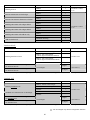
21
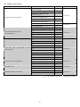
Example Data read: (01)94901234567894(11)030808(13)030810(17)040208(17)040305
Header: STX, Terminator: ETX, Scanner ID: Disable, Code ID mark: Disable,
Transmission of the number of digits: Disable, Prefix/Suffix: None, BCC: Disable
Extraction conditions
"Data transfer
regardless of error
result": Prohibit
"Data transfer
regardless of error
result": Permit
AIs specified
01,11,17
Delimiter
Comma
17,11
Output data
[STX]94901234567894,030808,040208[ETX]
[STX]040208,030808[ETX]
17,17
[STX]040208,040305[ETX]
12
Error
01,12
Error
01,01
Error
01,11,17
[STX]94901234567894,030808,040208[ETX]
17,11
[STX]040208,030808[ETX]
17,17
[STX]040208,040305[ETX]
12
[STX]01949012345678941103080813030810170
4020817040305[ETX]
01,12
01,01
(Note 1) Element strings will be output in the order of AIs specified.
(Note 2) If data read contains two or more element strings prefixed with the same AI, those element strings will be output in
the order arranged in that data read.
(Note 3) If data read does not contain a string prefixed with the specified AI or it contains such data but its number of digits
is more or less than the one defined for that AI, an error will result when the "Data transfer regardless of error
result" is prohibited.
22
(2) AI parenthesizing mode
In this mode, the scanner parenthesizes AIs contained in data read and outputs the edited data according to the
extraction conditions.
Extraction conditions
Extraction conditions
Choices
"Data transfer regardless of error result"
Permit/Prohibit
If the scanner fails to extract an AI-prefixed element string when the "Data transfer regardless of error result" is
permitted, it outputs the data read as is without editing.
Example Header: STX, Terminator: ETX, Scanner ID: Disable, Code ID mark: Disable,
Transmission of the number of digits: Disable, Prefix/Suffix: None, BCC: Disable
Extraction conditions
Data read
"Data transfer regardless 0194901234567894110308081303
of error result": Prohibit 081017040208
0194901234567894110308081303
081061704020817040305
"Data transfer regardless 0194901234567894110308081303
of error result": Permit
081017040208
0194901234567894110308081303
081061704020817040305
Output data
[STX](01)94901234567894(11)030808(13)03
0810(17)040208[ETX]
Error (Note 1)
[STX](01)94901234567894(11)030808(13)03
0810(17)040208[ETX]
[STX]01949012345678941103080813030
81061704020817040305[ETX]
(Note 1) Data from the head to element string 030810 prefixed with AI (13) can be normally extracted, but the
following data (as underlined below) causes an error since it starts with 6 that cannot start any AI.
(01)94901234567894(11)030808(13)03081061704020817040305
23
(3) AI table
In the AI-prefixed string extraction, the scanner edits data according to the Application Identifiers (AIs) defined
below.
AI
Format
Description
00
n2+n18
Serial Shipping Container Code (SSCC)
01
n2+n14
Global Trade Item Number (GTIN)
02
n2+n14
GTIN of Trade Items Contained in a logistic unit (For Use with AI 37 Only)
03
n2+n14
Reserved.
04
n2+n16
Reserved.
10
n2+an..20
Batch or Lot Number
11
n2+n6
Production Date (YYMMDD)
12
n2+n6
Due Date (YYMMDD)
13
n2+n6
Packaging Date (YYMMDD)
15
n2+n6
Best Before Date (YYMMDD)
17
n2+n6
Expiration Date (YYMMDD)
20
n2+n2
Product Variant
21
n2+an..20
Serial Number
22
n2+an..29
HIBCC (Health Industry Business Communication Council)--Quantity,
Date, Batch, and Link
23n
n3+n..19
Batch or Lot Number (Transitional Use)
240
n3+an..30
Additional Product Identification Assigned by the Manufacturer
241
n3+an..30
Customer Part Number
250
n3+an..30
Secondary Serial Number
251
n3+an...30
Reference to Source Entity
252
n3+n27
Global Serial Number
30
n2+n..8
Quantity
310n
n4+n6
Net Weight, Kilograms
311n
n4+n6
Length or 1st Dimension, Meters
312n
n4+n6
Width, Diameter, or 2nd Dimension, Meters
313n
n4+n6
Depth, Thickness, Height, or 3rd Dimension, Meters
314n
n4+n6
Area, Square Meters
315n
n4+n6
Volume, Liters
316n
n4+n6
Volume, Cubic Meters
(*)
(***)
(***)
24
(*)
(***)
(*)
(*)
(*)
(**)
AI
Format
Description
320n
n4+n6
Net Weight, Pounds (***)
321n
n4+n6
Length or 1st Dimension, Inches
322n
n4+n6
Length or 1st Dimension, Feet
323n
n4+n6
Length or 1st Dimension, Yards
324n
n4+n6
Width, Diameter, or 2nd Dimension, Inches
325n
n4+n6
Width, Diameter, or 2nd Dimension, Feet
326n
n4+n6
Width, Diameter, or 2nd Dimension, Yards
327n
n4+n6
Depth, Thickness, Height, or 3rd Dimension, Inches
328n
n4+n6
Depth, Thickness, Height, or 3rd Dimension, Feet
329n
n4+n6
Depth, Thickness, Height, or 3rd Dimension, Yards
330n
n4+n6
Gross Weight, Kilograms
331n
n4+n6
Length or 1st Dimension, Meters, Logistics
332n
n4+n6
Width, Diameter, or 2nd Dimension, Meters, Logistics
333n
n4+n6
Depth, Thickness, Height, or 3rd Dimension, Meters, Logistics
334n
n4+n6
Area, Square Meters, Symbology
335n
n4+n6
Gross Volume, Liters
336n
n4+n6
Gross Volume, Cubic Meters
337n
n4+n6
Kilograms per Square Meter (pressure)
340n
n4+n6
Gross Weight, Pounds
341n
n4+n6
Length or 1st Dimension, Inches, Logistics
342n
n4+n6
Length or 1st Dimension, Feet, Logistics
343n
n4+n6
Length or 1st Dimension, Yards, Logistics
344n
n4+n6
Width, Diameter, or 2nd Dimension, Inches, Logistics
345n
n4+n6
Width, Diameter, or 2nd Dimension, Feet, Logistics
346n
n4+n6
Width, Diameter, or 2nd Dimension, Yards, Logistics
347n
n4+n6
Depth, Thickness, Height, or 3rd Dimension, Inches, Logistics
348n
n4+n6
Depth, Thickness, Height, or 3rd Dimension, Feet, Logistics
349n
n4+n6
Depth, Thickness, Height, or 3rd Dimension, Yards, Logistics
350n
n4+n6
Area, Square Inches
351n
n4+n6
Area, Square Feet
352n
n4+n6
Area, Square Yards
25
(***)
(***)
(***)
(***)
(***)
(***)
(***)
(***)
(***)
(***)
(***)
(***)
(***)
(***)
(***)
(***)
(***)
(***)
(***)
(***)
(***)
(***)
(***)
(***)
(***)
(***)
(***)
(***)
(***)
(***)
AI
Format
Description
353n
n4+n6
Area, Square Inches, Logistics
(***)
354n
n4+n6
Area, Square Feet, Logistics
355n
n4+n6
Area, Square Yards, Logistics
356n
n4+n6
Net Weight, Troy Ounces
357n
n4+n6
Net Volume, Ounces
360n
n4+n6
Volume, Quarts
361n
n4+n6
Volume, Gallons
362n
n4+n6
Gross Volume, Quarts
363n
n4+n6
Gross Volume, Gallons
364n
n4+n6
Volume, Cubic Inches
365n
n4+n6
Volume, Cubic Feet
366n
n4+n6
Volume, Cubic Yards
367n
n4+n6
Gross Volume, Cubic Inches
368n
n4+n6
Gross Volume, Cubic Feet
369n
n4+n6
Gross Volume, Cubic Yards
37
n2+n..8
Quantity (For Use with AI 02 Only)
390n
n4+n15
Amount Payable--Single Monetary Area
391n
n4+n3+n15
Amount Payable and ISO Currency Code
392n
n4+n15
Amount Payable for a Variable Measure Trade Item--Single Monetary Area
393n
n4+n3+n15
Amount Payable for a Variable Measure Trade Item and ISO Currency
Code
400
n3+an..30
Customer's Purchase Order Number
401
n3+an..30
Consignment Number
402
n3+n17
Shipment Identification Number
403
n3+an..30
Routing Code
410
n3+n13
Ship to (Deliver to) EAN.UCC Global Location Number
411
n3+n13
Bill to (Invoice to) EAN.UCC Global Location Number
412
n3+n13
Purchased from EAN.UCC Global Location Number
413
n3+n13
Ship for (Deliver for) EAN.UCC Global Location Number
414
n3+n13
Identification of a Physical Location--EAN.UCC Global Location Number
415
n3+n13
EAN.UCC Global Location Number of the Invoicing Party
420
n3+an..20
Ship to (Deliver to) Postal Code Within a Single Postal Authority
(***)
(***)
(***)
(***)
(***)
(***)
26
(***)
(***)
(***)
(***)
(***)
(***)
(***)
(***)
AI
Format
Description
421
n3+n3+an..9
Ship to (Deliver to) Postal Code with Three-Digit ISO Country Code Prefix
422
n3+n3
Country of Origin of a Trade Item
423
n3+n15
Country of Initial Processing
424
n3+n3
Country of Processing
425
n3+n3
Country of Disassembly
426
n3+n3
Country of Final Processing
43
n2+n4+n7+an..10+n1
Carrier Assigned Tracking Number
7001
n4+n13
NATO Stock Number (NSN)
7002
n4+an..30
UN/ECE Meat Carcasses and Cuts Classification
7003
n4+n10
Effective term (YYMMDDHHMM)
7030
n4+n3+an..27
Approval Number of Processor with Three-Digit ISO Country Code,
Butchery
7031
n4+n3+an..27
Approval Number of Processor with Three-Digit ISO Country Code, 1st
Processing Place
703n
n4+n3+an..27
Approval Number of Processor with Three-Digit ISO Country Code, 2nd to
9th Processing Places
8001
n4+n14
Roll Products--Width, Length, Core Diameter, Direction, and Splices
8002
n4+an..20
Cellular Mobile Telephone Identifier
8003
n4+n14+an..16
EAN.UCC Global Returnable Asset Identifier (GRAI)
8004
n4+an..30
EAN.UCC Global Individual Asset Identifier (GIAI)
8005
n4+n6
Price Per Unit of Measure
8006
n4+n14+n2+n2
Identification of the Component of a Trade Item
8007
n4+an30
International Bank Account Number (IBAN)
8008
n4+n6+n6
Date and Time of Production (YYMMDDHHMMSS)
8018
n4+n18
EAN.UCC Global Service Relation Number (GSRN)
8020
n4+an25
Payment Slip Reference Number
8100
n4+n1+n5
UPC Coupon Extended Code--Number System Character and Offer Code
8101
n4+n1+n5+n4
UPC Coupon Extended Code--Number System Character, Offer Code, and
End of Offer Code
8102
n4+n1+n1
UPC Coupon Extended Code--Number System Character Preceded by Zero
90
n2+an..30
FACT Data Identifiers
91
n2+an..30
Company Internal Information--Company
92
n2+an..30
Company Internal Information--Company
27
AI
Format
Description
93
n2+an..30
Company Internal Information--Company
94
n2+an..30
Company Internal Information--Company
95
n2+an..30
Company Internal Information--Carrier
96
n2+an..30
Company Internal Information--Carrier
97
n2+an..30
Company Internal Information--Company
98
n2+an..30
Company Internal Information--Company
99
n2+an..30
Company Internal Information
(*) To indicate only year and month, DD must be filled with "00."
(**) n indicates the length of data.
(***) n indicates the decimal point position.
a
a3
a..3
Alphabetic characters
3 alphabetic characters, fixed length
Up to 3 alphabetic characters
n
n3
n..3
Numeric characters
3 numeric characters, fixed length
Up to 3 numeric characters
an
an3
an..3
Alphanumeric characters
3 alphanumeric characters, fixed length
Up to 3 alphanumeric characters
(Note 1) If the specified AI is variable in length and the number of digits in data read is less than the maximum number of
digits defined for the AI, then the output contains data read up to a GS (1Dh).
28
6.2.2 Data substitution mode
If the scanner reads a code specified by the "Code type" in this mode, it searches the data read for the specified string
(max. 16 ASCII characters), substitutes it with the specified substitution string (max. 16 ASCII characters), and
outputs it in the data transmission format selected in the scanner (see Chapter 8, Section 8.2).
Substitution conditions
Substitution conditions
Choices
“Code type”
Search string and substitution string
Any code
QR Code
iQR Code
PDF417
Data Matrix
MaxiCode
Aztec
UPC-A/EAN-13
UPC-E
EAN-8
Code 128
GS1-128 (EAN-128)
Codabar (NW-7)
Code 39
Code 93
Interleaved 2of5 (ITF)
Standard 2of5 (STF)
GS1 DataBar (RSS)
EAN.UCC Composite symbology
Max. 16 ASCII characters (00h to FFh) each
Example Code read: PDF417, Data: 12345678,
Header: STX, Terminator: ETX, Scanner ID: Disable, Code ID mark: Disable,
Transmission of the number of digits: Disable, Prefix/Suffix: None, BCC: Disable
Substitution condition
"Code type": PDF417
Search string and Substitution string
2A
4B
Output data
[STX]1A3B5678[ETX]
29
6.2.3 Data blocksorting mode
The scanner splits code data read into a maximum of 5 blocks at the specified split positions, sorts those blocks in the
specified order, and outputs it in the data transmission format selected in the scanner (see Chapter 8, Section 8.2).
Note: The split position must be specified by the number of digits from the head of code data read. Specifying the
number of digits exceeding that in the code data results in an error.
Blocksorting conditions
Blocksorting conditions
“Code type”
Choices
Any code
QR Code
iQR Code
PDF417
Data Matrix
MaxiCode
Aztec
UPC-A/EAN-13
UPC-E
EAN-8
Code 128
GS1-128 (EAN-128)
Codabar (NW-7)
Code 39
Code 93
Interleaved 2of5 (ITF)
Standard 2of5 (STF)
GS1 DataBar (RSS)
EAN.UCC Composite symbology
Example Code read: Code 128, Data: 1234567890,
Header: STX, Terminator: ETX, Scanner ID: Disable, Code ID mark: Disable,
Transmission of the number of digits: 4 digits, Prefix/Suffix: None, BCC: Disable
Split position
Order of blocks
Output data
3rd position, 8th position
Block 2, 1, 3
[STX]K00104567812390[ETX]
3rd position, 8th position
Block 1, 3
[STX]K000512390[ETX]
30
6.2.4 ADF script mode
The ADF script refers to a simple program language designed for editing of data read. It enables the following
functions.
(1) Extracting data that is fixed or variable in length
(2) Supporting Application Identifiers (AIs) in GS1-128 (EAN-128), GS1 DataBar (RSS) and EAN.UCC Composite
symbols
(3) Sorting data blocks into the specified order
(4) Collating data for verification
(5) Outputting same data repeatedly
(6) Performing four arithmetic operations including residue calculation, e.g., transformation of units
(7) Substituting data
(8) Comparing character strings
(9) Driving indicator LED and beeper
The ADF script mode can be programmed with the configuration software (ScannerSetting_2D). To configure the
scanner with the ADF script, transfer the script to the scanner or generate an ADF script QR code symbol with the
configuration software (ScannerSetting_2D) and use the scanner to read the symbol.
For the specifications and instructions for use of the ADF script, refer to the ADF Script User's Guide.
Note: The GTIN format conversion and ADF script mode cannot be used together with any of other edit modes (data
extraction mode, data substitution mode, and data blocksorting mode).
31
6.3
Point Scan Mode
In the point scan mode, you can aim at a target code by matching up the center spot of the marker beam with that code.
If there is no code at that center spot or the scanner cannot detect the marker beam due to high levels of ambient
lighting, the scanner cannot read anything. The point scan mode takes effect only when the marker is permitted to
light.
6.4
Scanning a Mirror Image 2D Code
If you enable the mirror image scanning with the configuration software (ScannerSetting_2D), the scanner can scan a
mirror image 2D code as well as a normal image. Note that when the mirror image scanning is enabled, the time
required for scanning may increase.
6.5
Scanning a Black-and-white Inverted Code
The scanner usually scans a black-and-white normal code (black cells/bars on a white background). You can switch
the scanner to scan a black-and-white inverted code (white cells/bars on a black background) or to scan both types of
codes while automatically identifying them, using the QR-coded parameter menu or the configuration software
(ScannerSetting_2D).
Note that the automatic detection scanning may take more time than normal code or inverted code scanning.
A black-and-white inverted code requires a black quiet zone of more than the number of cells defined in the code
specifications.
32
6.6
Scanning Structured Appended QR (iQR) Code Symbols
QR Code symbology can split data into a maximum of 16 blocks and encode each of them into a Structured Appended
QR Code symbol (model 1 or 2) or Structured Appended iQR Code symbol. Structured Appended Code scanning is
possible only with the same Code model.
The scanner can scan Structured Appended Code symbols and restore them to the original data string in edit mode,
batch edit mode, and non-edit mode, which you can select using the QR-coded parameter menu or configuration
software (ScannerSetting_2D).
Edit mode
The scanner accumulates and edits Structured Appended Code symbols read and then sends the edited data to the host
computer. If the total data volume of Structured Appended Code symbols exceeds 8 kilobytes, a read error will result
and the accumulated data will be discarded.
Batch edit mode (for QR Code Model 1 and Model 2 only)
If all the Structured Appended Code symbol which is split in less than four to be scanned lie within the readable area,
the scanner reads them all once and then edits and sends them to the host computer.
Non-edit mode
Each time a single split Code symbol is read, the scanner sends the data read to the host computer.
When scanning Structured Appended Code symbols, the scanner beeps in a different way from usual. That is, when
the scanner reads the first split code, it beeps twice and enters the Structured Appended Code scanning mode. When
the scanner completes the sequence of scanning, it beeps three times.
Note: If you scan any non-split QR(iQR) Code symbol or a code other than a QR(iQR) Code symbol midway through a
sequence of Structured Appended Code scanning, the scanner cancels the Structured Appended Code scanning, discards
the Structured Appended Code data already scanned, and sends the code scanned last.
Note: If the scanner switches to standby in the Auto-off mode (after approx. 5 seconds of holding down the trigger switch
or by releasing the trigger switch within 5 seconds) or the Structured Appended Code scanning interval exceeds approx. 3
seconds in any trigger switch operating mode except Auto-off mode, then the scanner discards the data scanned and
cancels the Structured Appended Code scanning sequence.
Note: If you scan a Structured Appended Code symbol of any other Code before completion of the current scanning
sequence, the scanner discards the data already scanned and starts a new scanning sequence.
33
6.7
Multi-line Barcode Scanning
The scanner can scan up to 3 lines of bar codes in the readable area at any one time. You can specify the number of
lines to be scanned, the data output order and output format using the configuration software (ScannerSetting_2D).*
6.7.1 Number of lines
The number of lines allowed for multi-line barcode scanning is 2 or 3. This setting is essential.
6.7.2 Data output order
You can specify the data output order by designating code types*1, heading characters*2, or the number of digits to be
scanned*3.
*1 Code types should be selected from readable bar codes you enable. This setting is essential.
*2 Up to two heading characters can be specified. If a question mark (?) is specified, it acts as a wild card. This setting
can be omitted.
*3 The number of digits to be scanned varies depending upon the code type. This setting is essential.
Note: The number of characters for Code 39 symbols should be specified including start and stop codes.
6.7.3 Output format
You can select either the header/terminator- or comma-delimited output format.
(1) Header/terminator-delimited output format
Specifying this format allows the scanner to output multiple lines of barcode data in succession in the data
transmission format selected (see Section 8.2) so that the headers and terminators act as delimiters. For UPC and EAN
codes, the number of digits will be omitted.
(2) Comma-delimited output format
Specifying this format allows the scanner to output multiple lines of barcode data delimited with commas in the data
transmission format selected (see Section 8.2). Note that the scanner outputs the code ID mark specified for the first
line barcode and the number of digits including the delimiter commas. The number of digits will not be omitted even
for UPC and EAN codes.
Note 1: Bar code types specified for multi-line barcode scanning cannot be read individually.
Note 2: The scanner cannot read multi-line barcodes of UPC/EAN with add-on.
Note 3: If linear components in a UPC/EAN Composite symbol are specified for multi-line barcode scanning,
EAN.UCC Composite symbols including the specified linear components cannot be read.
6.8
Scanning an SQRC (Security QR Code) Symbol
An SQRC symbol refers to a security QR Code symbol that consists of public and nonpublic data. The nonpublic data
can be read only when the encryption key configured in the scanner matches the one in the SQRC symbol.
To read an SQRC symbol with the scanner, it is necessary to enable SQRC scanning ("SQRC symbols only" or "both
SQRC symbols and QR Code symbols") using the configuration software (ScannerSetting_2D). The following SQRC
related parameters can be also specified--"Data transmission after match of encryption key," and "Data transmission
after mismatch of encryption key."
Note: SQRC scanning requires configuring an encryption key beforehand with the SQRC configuration software
(SQRC Setting) separately prepared.
34
Chapter 7
7.1
Beeper, Indicator LED, Marker Beam, and Illumination LEDs
Beeper
(1) Beeping
The scanner emits a short or long beeps, once or a couple of times as described below.
The beeper emits a short beep when:
- the scanner has read a code successfully,
- code data read matches the master data in the data verification mode,(2-point:2 beeps, n-point:1 beep)
- the scanner has read a Structured Appended QR (iQR) Code symbol,
- the "Start setting" or "End setting" code is read (3 beeps) or the parameter setting QR Code symbols are read (1
beep) from the QR-coded parameter menu (given in Chapter 12),
- the configuration software (ScannerSetting_2D) starts up or accepts new settings (3 beeps), or
- the scanner has read a batch-process QR Code symbol generated with the configuration software
(ScannerSetting_2D) (3 beeps).
- a Bluetooth® wireless link is established, or
- the charge of the battery cartridge has lowered, turning the scanner off (5 beeps, slightly longer).
The beeper emits a long beep when:
- code data read does not match the master data in the data verification mode,
- the scanner has read Structured Appended QR (iQR) Code symbols in edit mode and the accumulated data exceeds 8
kilobytes,
- a master code has the wrong number of digits during registration of master data,
- a code other than a parameter setting code is read during parameter setting by the QR-coded parameter menu,
- a transmission error or timeout occurred when the scanner was communicating with the configuration software
(ScannerSetting_2D),
- the encryption key of data read does not match the one configured in the scanner in SQRC scanning (when the "data
transmission after mismatch of encryption key" is disabled),
- a communications error has occurred, or
- an invalid control command is received.
- a Bluetooth® wireless link is broken,
- transfer of communications adapter parameter settings is ended normally (1 beep) or abnormally (3 beeps), or
- the scanner has failed to save the parameter settings entered with the QR-coded parameter menu or the configuration
software.
When the scanner is turned on, the configuration software (ScannerSetting_2D) provides a choice of beeper ON/OFF
(default: ON), but does not provide a choice of beeper tone.
You can disable the beeper using the QR-coded parameter menu or configuration software (ScannerSetting_2D)*. In
any of the following cases, however, the beeper sounds regardless of that beeper setting:
- when you make settings by scanning the QR-coded parameter menu,
- when the scanner receives a beeper-ON command from the host computer,
- when the configuration software (ScannerSetting_2D) starts up or any setting you have made is established,
- when the scanner reads a batch-process QR Code symbol, and
- when the parameter values are saved by a PW command (refer to Appendix 2).
- when the Bluetooth wireless link is established or broken,
- when the charge of the battery cartridge has lowered,
-when the scanner has failed to save the parameter settings, or
-when transfer of communications adapter parameter settings is normally ended.
35
(2) Adjusting the beeper volume
You can adjust the beeper volume to three levels--high, medium and low--using the QR-coded parameter menu or
configuration software (ScannerSetting_2D). The factory default is High.
Note: Enabling the Bluetooth interface with the "Start operation" QR Code symbol allows the beeper volume
adjustment.
Each time the "Beeper volume" QR Code symbol is read, the beeper volume cycles as shown below. The factory
default is High.
High
Medium
Low
Even if the scanner is turned off, this setting will be retained.
36
7.2
Indicator LED
The indicator LED lights or flashes in blue, green, red or orange as described below.
The indicator LED lights in blue when:
- the scanner has read a code successfully,
- the scanner has read a Structured Appended QR (iQR) Code symbol,
- code data read matches the master data in the data verification mode, or
- master data has been successfully registered in the data verification mode.
The indicator LED lights in green when:
- the scanner is ready to register master data.
The indicator LED lights in red when:
- the trigger switch is pressed when the trigger switch control is disabled.
The indicator LED flashes in red when:
- the scanner has received an abnormal control command,
- the scanner has failed to edit data read,
- no master data has been registered in the data verification mode(n-point).
- code data read does not match the master data in the data verification mode,
- a master code has the wrong number of digits during registration of master data,
- the scanner has read Structured Appended QR (iQR) Code symbol in edit mode and the accumulated data exceeds 8
kilobytes,
- the scanner has failed to save parameter values specified with the configuration software (ScannerSetting_2D),
QR-coded parameter menu, or control commands,
- a code other than a parameter setting code is read during parameter setting by the QR-coded parameter menu,
- a transmission error or timeout occurred when the scanner was communicating with the configuration software
(ScannerSetting_2D),
- a run-time error has occurred in ADF script,
- the trigger switch is pressed when a Bluetooth wireless link is broken.
- the trigger switch is pressed on "End operation."
The indicator LED flashes in orange when:
- the charge of the battery cartridge has lowered or
- the scanner turns itself off due to low charge of the battery cartridge.
The indicator LED flashes in blue when:
- the "Start setting" or "End setting" code is read from the QR-coded parameter menu (given in Chapter 12),
- the scanner starts or ends a sequence of Structured Appended QR (iQR) Code scanning,
- the parameter values are saved by a PW command (refer to Appendix 2),
- scanner as master is establishing the Bluetooth wireless link.
- scanner as slave is establishing the Bluetooth wireless link
37
The indicator LED can be disabled with the QR-coded parameter menu or configuration software
(ScannerSetting_2D). In any of the following cases, however, the indicator LED comes on regardless of the current
LED setting.
- When the scanner is being customized with the QR-coded parameter menu (Chapter 12),
- When the scanner receives an LED-ON command (LB, LG or LR) from the host computer (refer to Appendix 2),
- When the configuration software (ScannerSetting_2D) starts up or any setting is newly established,
- When the scanner reads a batch-process QR Code symbol,
- When the parameter values are saved by a PW command (refer to Appendix 2),
- When the scanner is in the scanner entry mode (refer to control command "E" in Appendix 2),
- When a master code is being registered or the registration is completed,
- When any error has occurred during registration of a master code,
- When the scanner has failed to save parameter values specified with the configuration software (ScannerSetting_2D),
QR-coded parameter menu, or control commands,
- When a run-time error has occurred in ADF script, or
- When the trigger switch is pressed when the trigger switch control is disabled.
- the Bluetooth wireless link status is displayed,
- the charge of the battery cartridge has lowered,
- the charging/discharging state is displayed,
- the parameter transfer status from the scanner to the communications adapter is displayed, or
- the scanner failed to save setting.
38
7.3
Marker Beam
The red marker beam (semiconductor laser) comes on to indicate the scanning area as a guide.
The marker provides a choice of the three modes--normal marker mode, marker-OFF mode and marker-ON mode that
can be selected by using the QR-coded parameter menu or the configuration software (ScannerSetting_2D).
(1) Normal marker mode
When the trigger switch is in Auto-off mode or auto-off of the Auto stand mode:
When the scanner is ready to scan (that is, within approx. 5 seconds from the depression of the trigger switch or until
completion of reading from that), the marker beam remains on. If you release the trigger switch when the scanner is
ready, the marker beam will go off.
When the trigger switch is in Momentary switching mode or Alternate switching mode:
In the momentary switching mode, holding down the trigger switch turns on the marker beam.
When the scanner is ready to scan (that is, while the trigger switch is held down in the momentary switching mode or
when the scanner is ready to scan in the alternate switching mode), the marker beam remains on. When the scanner is
on standby (that is, the trigger switch is released in the momentary switching mode or when the scanner is on standby
in the alternate switching mode), the marker beam will go off.
When the trigger switch is in Momentary switching mode (Reverse Type):
In the momentary switching mode (Reverse Type), the marker beam remains on while the trigger switch is in the
released position.
When the scanner is ready to scan (that is, the trigger switch is released in the momentary switching mode reverse
type), the marker beam remains on. When the scanner is on standby (that is, while the trigger switch is held down in
the momentary switching mode reverse type), the marker beam will go off.
When the trigger switch is in Continuous reading mode 1 or 2:
Turning the scanner on activates the marker and keeps it on.
If the scanner receives the Z, READOFF or LOFF command, it turns off the marker beam; if it receives the R,
READON or LON command, it keeps the marker beam on.
When the trigger switch is in Auto sensing mode or auto sense state of the Auto stand mode:
When the scanner senses a code coming into the readable area and becomes ready to scan, it automatically turns on the
marker beam. After approx. 3 seconds from completion of scanning or if scanning is not completed within approx. 3
seconds, the scanner switches to standby and turns off the marker beam.
(2) Marker-OFF mode
The marker beam will not come on under any conditions.
(3) Marker-ON mode
When the scanner switches to standby, the marker beam is turned on for approx. 30 seconds.
When it is ready to scan, the marker beam remains on.
7.4
Illumination LEDs
When the scanner is ready to scan, the illumination LEDs are turned on.
The illumination LEDs provide the two choices--ON, OFF by using the configuration software (ScannerSetting_2D).
Enable or disable of “Power save mode” can be selected. The default setting is “Enable”.
When “Power save mode” is enabled, 20% power consumption is saved by less brightness of the illumination LEDs.
(Note) When “Power save mode” is enabled, a reading distance may be shorter under 500 lx ambient illumination.
39
Chapter 8
8.1
Communication
Bluetooth Interface
The QR-coded parameter menu and the configuration software (ScannerSetting_2D) provide a choice of various
communications conditions. Under the communications conditions you choose, code data read can be transferred to
the external equipment or computer.
(1) Communications protocol
When the scanner is in SPP profile, you can select either non-acknowledge mode, ACK/NAK mode, or data
packaging mode.
Non-acknowledge mode (default)
The scanner transfers code data read, regardless of the CTS signal level.
ACK/NAK mode
The scanner transfers code data read, regardless of the CTS signal level. After that, however, it waits for the response
from the host and processes it. The configuration software (ScannerSetting_2D) only provides ACK/NAK timeout
settings from 100 ms to 9.9 s in 100 ms increments.
ACK: Normal end
NAK: Retransfer
Data packaging mode
- To host
The scanner wraps the code data in a packet with a CRC for transfer to a commercially available Bluetooth device or
other equipment. For further details, see Section 8.4.
(2)Timeout period for slave to wait for a connection request
The scanner, as a slave, waits for a connection request from the master for the specified timeout period--2 (default), 4,
10, or 30 minutes.
If the scanner cannot receive a connection request from the master within the specified timeout period, it switches to
standby, the same status as the Bluetooth wireless link has been broken.
40
8.2
HID Profile
The scanner supports the Human Interface Device Profile (HID) that enables connecting to an iPhone or iPad
equipped with Bluetooth module that is compatible with Bluetooth® Specification Ver. 2.1+EDR.
(1) CAPS Lock state
Select the CAPS Lock ON or OFF to match the state of the host computer. (Default: CAPS Lock OFF)
(2) Keyboard type
Select the type of the connected keyboard. (Default: Type 106, Japanese)
(3) Numeric data transmission format
Select the “inboard numeric keys” or “numeric keyboard” on the connected keyboard. (Default: Inboard numeric
keys)
(4) Binary data conversion
Select the conversion type to be applied to data read, from the following:
・”No conversion”(ASCII) (default) : Outputs 00h to 7Fh data in ASCII format bytewise. Selecting this parameter
does not output 80h to FFh data. Scanning operation is completed, when data
is 80h to FFh.
・"Binary conversion"
:Converts 00h to FFh data to binary format bytewise.and outputs it.
・"Kanji conversion"
:Converts 00h to FFh data to Shift-JIS format and outputs it, two bytes at a
time. If there is any data to which this Kanji conversion cannot apply, it
converts such data to binary format bytewise and outputs it instead.
8140 to 9FFC、E040 to EFFC are allocated for Kanji
e.g.) When scanning code data is “Kanji”,
Data
: Kanji
Shift JIS : 8ABF 8E9A
Binary conversion format
Output data
Note
No conversion
No output
Scanning operation is completed only.
Binary conversion
8Ah BFh 8Eh 9Ah
Assigned
characters
Output with binary data 1 byte by 1 byte
Kanji conversion
“Kanji”
Output with Kanji conversion (Note)
Note that some applications may fail to output converted data as it is displayed.
41
8.3
Communication Format
Data transmission format
Select one of the following two data transmission formats.
Header
Scanner
ID
Code ID
mark
Prefix
Header
Scanner
ID
Prefix
Code ID
mark
No. of digits
n1
n2
n3
n4
No. of digits
n1
n2
n3
n4
Code data
Suffix
Terminator
BCC
Code data
Suffix
Terminator
BCC
(1) Header/Terminator
The following choices are available.
SPP profile
Header:
None (default), STX, or User Selection
Terminator: CR (default), None, LF, CR/LF, ETX, or User Selection
HID profile
Header:
None (default), TAB, ESC, ENTER, or User Selection
Terminator: ENTER (default), None, TAB, ESC, or User Selection
For details, refer to Chapter 11.
(2) Scanner ID
A scanner ID is a unique serial number assigned to an individual scanner at the time of shipment. It consists of six
numerals.
(3) Prefix/Suffix
A prefix or suffix consists of up to eight ASCII characters (00h to FFh). You can set a prefix or suffix with the
configuration software (ScannerSetting_2D). (Default: No prefix or suffix)
(4) BCC
The Block Character Check (BCC) exclusive-ORs all bits at the same bit level in characters following the header and
preceding the terminator in a transmission block to generate a horizontal parity byte to be transferred in a binary code.
The BCC can be enabled or disabled. If no header is prefixed or the USB keyboard interface is selected, no BCC will
be transferred.
42
(5) Code ID mark
This optional field specifies the code system. It offers ten combinations with five code ID marks (Type 1, Type 2,
Type 3, Type 4, and user-defined) and two output modes (coupling and separating) as listed below.
You can also select whether or not to transmit the code ID mark. (Default: No transmission)
(1/2)
Code ID mark
Code type
Type 1
Coupling
2D codes
QR Code
Structured
Appended QR
Code
Separating
Q
Type 2
Coupling
Separating
Q
Edit mode
Q
Q
Batch edit mode
Q
Q
Non-edit mode
MicroQR Code
S
S
Q
Q
SQRC
Q
Q
iQR Code
G
G
G
G
Structured
Appended iQR
Code
Edit mode
S
S
MaxiCode
X
X
PDF417
Y
Y
MicroPDF417
Y
Y
Square
Z
Z
Rectangular
Z
Z
J
J
Data Matrix
Non-edit mode
Aztec
43
(1/2)
Code ID mark
Code type
Type 1
Coupling
Bar codes
UPC-A
UPC-E
EAN-13
Without add-on
With 2-digit
add-on
Linear component
With 5-digit
add-on
Linear component
Add-on
With 2-digit
add-on
Linear component
With 5-digit
add-on
Linear component
Add-on
Add-on
Without add-on
With 5-digit
add-on
EAN-8
Add-on
Without add-on
With 2-digit
add-on
Linear component
Add-on
Linear component
Add-on
Without add-on
With 2-digit
add-on
With 5-digit
add-on
Separating
A
Linear component
Add-on
Linear component
Add-on
Type 2
Coupling
Separating
A
A
A
None
None
A
A
None
None
C
E
C
E
None
None
C
E
None
None
A
F
A
F
None
None
A
F
None
None
B
FF
B
FF
None
None
B
FF
None
None
Interleaved 2of5
I
I
Standard 2of5(short)
H
H
Standard 2of5(normal)
H
H
Code 39
M
M
Code 39 Full ASCII
M
M
Codabar (NW-7)
N
N
Code 128
K
K
GS1-128 (EAN-128)
W
W
Code 93
L
L
GS1 DataBar (RSS) (Note 1)
R
R
44
(1/2)
Code ID mark
Code type
EAN.UCC
Composite
symbols
RSS
RSS (Note 1) CC-A
RSS (Note 1) CC-B
UPC-A CC-A,
UPC-A CC-B
Type 1
CC-A, CC-B
UPC-A
Without add-on
With
2-digit
add-on
Linear
component
With
5-digit
add-on
Linear
component
Add-on
Add-on
CC-A, CC-B
EAN-13 CC-A,
EAN-13 CC-B
EAN-13
Without add-on
With
2-digit
add-on
Linear
component
With
5-digit
add-on
Linear
component
Add-on
Add-on
CC-A, CC-B
UPC-E CC-A,
UPC-E CC-B
UPC-E
Without add-on
With
2-digit
add-on
Linear
component
With
5-digit
add-on
Linear
component
Add-on
Add-on
CC-A, CC-B
EAN-8 CC-A,
EAN-8 CC-B
EAN-8
Without add-on
With
2-digit
add-on
Linear
component
With
5-digit
add-on
Linear
component
Add-on
Add-on
Coupling
Separating
Coupling
V
R
V
Separating
R
None
Y (Note 2)
None
Y (Note 2)
V
A
V
A
V
A
V
A
None
None
None
None
V
A
V
A
None
None
None
None
None
Y (Note 2)
None
Y (Note 2)
V
A
V
F
V
A
V
F
None
None
None
None
V
A
V
F
None
None
None
None
None
Y (Note 2)
None
Y (Note 2)
V
C
V
E
V
C
V
E
None
None
None
None
V
C
V
E
None
None
None
None
None
Y (Note 2)
None
Y (Note 2)
V
B
V
FF
V
B
V
FF
None
None
None
None
V
B
V
FF
None
None
None
None
None
Y (Note 2)
None
Y (Note 2)
GS1-128 (EAN-128)
V
W
V
W
CC-A, CC-B, CC-C
None
Y (Note 2)
None
Y (Note 2)
CC-A, CC-B
EAN-128 CC-A,
EAN-128 CC-B,
EAN-128 CC-C
Type 2
45
(2/2)
Code ID mark
Code type
Type 3
Coupling
2D codes
QR Code
Separating
Type 4 (Note 3)
Coupling
Separating
P01
]Qm
Edit mode
P01
]Qm
Batch edit mode
P01
]Qm
Non-edit mode
P01
S (Note 4)
MicroQR Code
P01
Q (Note 4)
SQRC
P01
Q (Note 4)
G
]Qm
G
]Qm
Structured
Appended QR
Code
iQR Code
Structured
Appended iQR
Code
Edit mode
Non-edit mode
MaxiCode
PDF417
MicroPDF417
Data Matrix
S
S
P02
]Um
X
]L0
X
]L0
Square
P00
]dm
Rectangular
P00
]dm
z
]zm
Aztec
46
(2/2)
Code ID mark
Code type
Type 3
Coupling
Bar codes
UPC-A
UPC-E
EAN-13
Without add-on
Linear component
With 5-digit
add-on
Linear component
EAN-8
Add-on
Add-on
Without add-on
Linear component
With 5-digit
add-on
Linear component
Add-on
Add-on
Without add-on
Add-on
Linear component
Add-on
Without add-on
With 2-digit
add-on
With 5-digit
add-on
A
]X3
]X0
None
None
]X1 (Note 2)
A
]X3
]X0
None
None
A
]X3
]X0
None
None
]X1 (Note 2)
A
]X3
]X0
None
None
]X2 (Note 2)
]E0
A
]E3
]E0
None
None
]E1 (Note 2)
A
]E3
]E0
None
None
]E2 (Note 2)
A
Linear component
Add-on
Linear component
Add-on
]X2 (Note 2)
]X0
A
Linear component
Separating
]X0
A
With 2-digit
add-on
With 5-digit
add-on
Coupling
A
With 2-digit
add-on
With 2-digit
add-on
Separating
Type 4 (Note 3)
]E4
A
]E5
]E4
None
None
]E1 (Note 2)
A
]E6
]E4
None
None
]E2 (Note 2)
Interleaved 2of5
F
]Im
Standard 2of5(short)
G
]R0
Standard 2of5(normal)
G
]S0
Code 39
B
]Am
Code 39 Full ASCII
B
]Am
Codabar (NW-7)
C
]Fm
Code 128
D
]Cm
GS1-128 (EAN-128)
K
]C1
Code 93
E
]G0
GS1 DataBar (RSS) (Note 1)
R
]e0
47
(2/2)
Code ID mark
Code type
EAN.UCC
Composite
symbols
RSS
RSS (Note 1) CC-A
RSS (Note 1) CC-B
UPC-A CC-A,
UPC-A CC-B
Type 3
CC-A, CC-B
UPC-A
Without add-on
With
2-digit
add-on
Linear
component
With
5-digit
add-on
Linear
component
Add-on
Add-on
CC-A, CC-B
EAN-13 CC-A,
EAN-13 CC-B
EAN-13
Without add-on
With
2-digit
add-on
Linear
component
With
5-digit
add-on
Linear
component
Add-on
Add-on
CC-A, CC-B
UPC-E CC-A,
UPC-E CC-B
UPC-E
Without add-on
With
2-digit
add-on
Linear
component
With
5-digit
add-on
Linear
component
Separating
T
R
Coupling
]e0
Separating
None
X (Note 2)
None
T
A
]X0
T
A
]X3
]X0
None
None
None
]X1 (Note 2)
T
A
]X3
]X0
None
None
None
]X2 (Note 2)
None
X (Note 2)
]e0 (Note 2)
T
A
]E0
T
A
]E3
]E0
None
None
None
]E1 (Note 2)
T
A
]E3
]E0
None
None
None
]E2 (Note 2)
None
X (Note 2)
]e0 (Note 2)
T
A
]X0
T
A
]X3
]X0
None
None
]X1 (Note 2)
T
A
]X3
]X0
None
None
None
]X2 (Note 2)
None
X (Note 2)
]e0 (Note 2)
T
A
]E4
T
A
]E5
]E4
None
None
None
]E1 (Note 2)
T
A
]E6
]E4
None
None
None
]E2 (Note 2)
None
X (Note 2)
]e0 (Note 2)
GS1-128 (EAN-128)
T
K
]e0
CC-A, CC-B, CC-C
None
X (Note 2)
None
Add-on
EAN-8
Without add-on
With
2-digit
add-on
Linear
component
With
5-digit
add-on
Linear
component
Add-on
Add-on
CC-A, CC-B
EAN-128 CC-A,
EAN-128 CC-B,
EAN-128 CC-C
Coupling
None
Add-on
CC-A, CC-B
EAN-8 CC-A,
EAN-8 CC-B
Type 4 (Note 3)
48
(Note 1) GS1 DataBar (RSS) represents: GS1 DataBar Omnidirectional (RSS-14), GS1 DataBar Truncated (RSS-14
Truncated), GS1 DataBar Limited (RSS-14 Limited), GS1 DataBar Stacked (RSS-14 Stacked), GS1 DataBar
Expanded (RSS Expanded), GS1 DataBar Stacked Omnidirectional (RSS-14 Stacked Omnidirectional), and GS1
DataBar Expanded Stacked (RSS Expanded Stacked).
(Note 2) These code ID marks are contained in code data.
(Note 3) Type 4 is a code ID mark system compliant with the AIM USA “Guidelines on Symbology Identifiers.” The “m”
suffix is a modifier character that differs depending upon options of individual symbologies as defined below.
Code Type
2D
codes
QR Code
iQR Code
MaxiCode
Data Matrix
Aztec
Bar
codes
Interleaved
2of5
Code 39
Code 39 Full
ASCII
Codabar
Code 128
“m”
(Modifier
character)
0
Options
Model 1
1
Model 2
A
No FNC1 in the 1st character positions from start code
C
FNC1 in the 1st character positions from start code
E
FNC1 in the 2nd character positions from start code
0
mode 4, mode 5
1
mode 2, mode 3
1
ECC-200
2
ECC-200 (FNC1 in the 1st or 5th character position from start code)
3
ECC-200 (FNC1 in the 2nd or 6th character position from start code)
0
No options
1
FNC1 preceding the 1st message character
2
FNC1 subsequent to the 1st character or digit pair
0
Scanning enabled, without a check digit
1
Scanning enabled, with a check digit
(Check digit transmission enabled)
3
Scanning enabled, with a check digit
(Check digit transmission disabled)
0
Scanning enabled, without a check digit
1
Scanning enabled, with a check digit
(Check digit transmission enabled)
3
Scanning enabled, with a check digit
(Check digit transmission disabled)
0
Scanning enabled, without a check digit
1
Scanning enabled, with a check digit
(Check digit transmission enabled)
3
Scanning enabled, with a check digit
(Check digit transmission disabled)
0
No FNC1 in the 1st and 2nd character positions from start code
2
FNC1 in the 2nd character position from start code
Example: The code ID mark for Interleaved 2of5 with option “Scanning enabled, with a check digit (Check digit
transmission disabled)” is ]I3.
]: Flag character (ASCII 93h)
I: Code character (Interleaved 2of5)
3: Modifier character (See the table above.)
(Note 4) For code ID marks not compliant with the AIM USA “Guidelines on Symbology Identifiers,” same characters as
ones defined in Type 1 apply.
49
(6) Number of digits
This optional field specifies whether or not to transmit the number of digits (2 or 4 bytes) of code data to transmit or
disables the transmission (default). Note that UPC and EAN codes (except GS1-128 (EAN-128)) skip this field.
4 digits (4 byte) transmission
n1: thousands (0 to 9)
n2: hundreds (0 to 9)
n3: tens (0 to 9)
n4: units (0 to 9)
2 digits (2 byte) transmission
n1: tens (0 to 9)
n2: units (0 to 9)
(7) Code data
The data format for each symbology is described below.
QR Code / MicroQR Code / iQR Code
Code data read will be transmitted as is.
Structured Appended QR Code / Structured Appended iQR Code
In edit mode and batch edit mode (Structured Appended QR Code only): The scanner edits code data read and then
transmits it. It does not transmit the code number, number of splits, or parity.
In non-edit mode: The scanner transmits the code number, the number of splits, parity, and code data read. The code
number and the number of splits are 1 byte each and the parity, 2 bytes in hexadecimal format.
SQRC
Code data read will be transmitted as is. When “Enable transmission of disclosed data only” is selected in “SQRC
Encryption key match”, it transmits only non-disclosure data.
X1 X2 ・・・Xn-1 Xn Y1 Y2 ・・・Ym-1 Ym
Xn:Disclosure data
Ym:Non-disclosure data
When “Disclosure data plus non-disclosure data” is selected, the following format applies.
X1 X2 ・・・Xn-1 Xn Y1 Y2 ・・・Ym-1 Ym
When “Transmit only non-disclosure data” is selected, the following format applies.
Y1 Y2 ・・・Ym-1 Ym
PDF417, MicroPDF417, MaxiCode , Data Matrix , and Aztec
Code data read will be transmitted as is.
50
UPC-A
You can select whether or not to transmit the padding character "0," number system character "S," and a check digit to
the host. Disabling the transmission of the number system character "S" automatically disables the transmission of the
padding character "0."
The conversion to the GTIN format is selectable. For the GTIN format conversion, refer to Section 8.3.
When the conversion to the GTIN format is disabled, the following format applies.
0 S X1 X2 X3 X4 X5 X6 X7 X8 X9 X10 C/D
0: Padding character for adjustment of the data length
S: Number system character
UPC-A with add-on
A code ID mark precedes add-on code data under the conditions "Code ID mark: Type 4" and "Code ID mark output
mode: Separating." (For details about the code ID mark, refer to (5) Code ID mark on pages 42 to 46.)
The conversion to the GTIN format is selectable. For the GTIN format conversion, refer to Section 8.3.
When the conversion to the GTIN format is disabled, the following formats apply.
With 2-digit add-on:
0 S X1 X2 X3 X4 X5 X6 X7 X8 X9 X10 C/D X11 X12
With 5-digit add-on:
0 S X1 X2 X3 X4 X5 X6 X7 X8 X9 X10 C/D X11 X12 X13 X14 X15
0: Padding character for adjustment of the data length
S: Number system character
X11-15: Add-on code data
51
UPC-E
You can select whether or not to transmit the padding character "0," number system character "S," and a check digit to
the host. Disabling the transmission of the number system character "S" automatically disables the transmission of the
padding character "0."
The conversion to the GTIN format or to the UPC-A are selectable. For the GTIN format conversion, refer to Section
8.3.
When the conversion to the GTIN format is disabled, the following formats apply.
- Conversion to UPC-A disabled
X1 X2 X3 X4 X5 X6 C/D
- Conversion to UPC-A enabled
0 S X1 X2 X6 0 0 0 0 X3 X4 X5 C/D
X6=0-2
0 S X1 X2 X3 0 0 0 0 0 X4 X5 C/D
X6=3
0 S X1 X2 X3 X4 0 0 0 0 0 X5 C/D
X6=4
0 S X1 X2 X3 X4 X5 0 0 0 0 X6 C/D
X6=5-9
0: Padding character for adjustment of the data length
S: Number system character
UPC-E with add-on
A code ID mark precedes add-on code data under the conditions "Code ID mark: Type 4" and "Code ID mark output
mode: Separating." (For details about the code ID mark, refer to (5) Code ID mark on pages 42 to 46.)
The conversion to the GTIN format or to the UPC-A are selectable. For the GTIN format conversion, refer to Section
8.3.
When the conversion to the GTIN format is disabled, the following formats apply.
With 2-digit add-on:
- Conversion to UPC-A disabled
0 X1 X2 X3 X4 X5 X6 C/D X7 X8
- Conversion to UPC-A enabled
0 S X1 X2 X6 0 0 0 0 X3 X4 X5 C/D X7 X8
X6=0-2
0 S X1 X2 X3 0 0 0 0 0 X4 X5 C/D X7 X8
X6=3
0 S X1 X2 X3 X4 0 0 0 0 0 X5 C/D X7 X8
X6=4
0 S X1 X2 X3 X4 X5 0 0 0 0 X6 C/D X7 X8
X6=5-9
With 5-digit add-on:
- Conversion to UPC-A disabled
0 X1 X2 X3 X4 X5 X6 C/D X7 X8 X9 X10 X11
- Conversion to UPC-A enabled
0 S X1 X2 X6 0 0 0 0 X3 X4 X5 C/D X7 X8 X9 X10 X11
X6=0-2
0 S X1 X2 X3 0 0 0 0 0 X4 X5 C/D X7 X8 X9 X10 X11
X6=3
0 S X1 X2 X3 X4 0 0 0 0 0 X5 C/D X7 X8 X9 X10 X11
X6=4
0 S X1 X2 X3 X4 X5 0 0 0 0 X6 C/D X7 X8 X9 X10 X11
X6=5-9
0: Padding character for adjustment of the data length
S: Number system character
X7-11: Add-on code data
52
EAN-13
You can select whether or not to transmit the two prefix characters "P1" and "P2" and a check digit to the host. The
conversion to the ISBN/ISSN format is selectable. Enabling the conversion allows EAN-13 code with prefix
characters 978 or 979 to be converted into the ISBN format, and EAN-13 code with prefix characters 977, into the
ISSN format.
The conversion to the GTIN format is also selectable. For the GTIN format conversion, refer to Section 8.3.
When the conversion to the GTIN format is disabled, the following formats apply.
- Conversion to ISBN/ISSN disabled
P1 P2 P3 X1 X2 X3 X4 X5 X6 X7 X8 X9 C/D
Pn: Prefix characters
- Conversion to ISBN/ISSN enabled
To the ISBN format
X1 X2 X3 X4 X5 X6 X7 X8 X9 C/D (*1)
To the ISSN format
X1 X2 X3 X4 X5 X6 X7 C/D (*1)
( 1)
* Check digits in the ISBN/ISSN format are calculated (MOD-11) and transferred to the host.
EAN-13 with add-on
A code ID mark precedes add-on code data under the conditions "Code ID mark: Type 4" and "Code ID mark output
mode: Separating." (For details about the code ID mark, refer to (5) Code ID mark on pages 42 to 46.)
The conversion to the GTIN format is selectable. For the GTIN format conversion, refer to Section 8.3.
When the conversion to the GTIN format is disabled, the following formats apply.
With 2-digit add-on:
P1 P2 P3 X1 X2 X3 X4 X5 X6 X7 X8 X9 C/D X10 X11
With 5-digit add-on:
P1 P2 P3 X1 X2 X3 X4 X5 X6 X7 X8 X9 C/D X10 X11 X12 X13 X14
Pn: Prefix characters
X10-14: Add-on code data
EAN-8
You can select whether or not to transmit a check digit to the host. The conversion to EAN-13 is selectable.
The conversion to the GTIN format is also selectable. For the GTIN format conversion, refer to Section 8.3.
When the conversion to the GTIN format is disabled, the following formats apply.
- Conversion to EAN-13 disabled
P1 P2 P3 X1 X2 X3 X4 C/D
- Conversion to EAN-13 enabled
0 0 0 0 0 P1 P2 P3 X1 X2 X3 X4 C/D
Pn: Prefix characters
53
EAN-8 with add-on
A code ID mark precedes add-on code data under the conditions "Code ID mark: Type 4" and "Code ID mark output
mode: Separating." (For details about the code ID mark, refer to (5) Code ID mark on pages 42 to 46.)
The conversion to the GTIN format is selectable. For the GTIN format conversion, refer to Section 8.3.
When the conversion to the GTIN format is disabled, the following formats apply.
With 2-digit add-on:
P1 P2 P3 X1 X2 X3 X4 C/D X5 X6
With 5-digit add-on:
P1 P2 P3 X1 X2 X3 X4 C/D X5 X6 X7 X8 X9
Pn: Prefix characters
X5-9: Add-on code data
Code 39
Code data read will be transmitted as is.
You can select whether or not to transmit start and stop codes ("*").
Interleaved 2of5, Standard 2of5
The scanner transmits code data read, starting from the character following the start code to the one preceding the stop
code. No start/stop codes will be transmitted.
Codabar (NW-7)
The scanner transmits code data read including the start/stop codes. You can select whether or not to transmit
start/stop codes.
Code 128 (GS1-128 (EAN-128))
The scanner transmits code data read, starting from the character following the start code to the one preceding the
check digit. Start/stop codes, FNC codes, or check digit will not be transmitted. Note that FNC1 placed in character
positions other than the 1st and 2nd ones from the start code will be converted to GS (1Dh) and transferred.
The conversion to the GTIN format is also selectable. For the GTIN format conversion, refer to Section 8.3.
Code 93
The scanner transmits code data read, excluding start and stop codes and a check digit.
54
GS1 DataBar (RSS)
Code data read will be transmitted as is.
FNC1 of GS1 DataBar Expanded (RSS Expanded) will be converted to GS(1Dh) and can be selectable from either
transferred or user selection.
The conversion to the GTIN format is also selectable. For the GTIN format conversion, refer to Section 9.5.
GS1 DataBar (RSS) Composite symbols
Code data read will be transmitted as is.
Under the conditions “Code ID mark: Type 1” and “Code ID mark output mode: Separating,” a separator (GS: 1Dh)
and 2D code ID mark are inserted between the linear component and 2D Composite component. (For details about the
code ID mark, refer to (5) Code ID mark)
Under the conditions “Code ID mark: Type 4” and “Linear component length (RSS/EAN-128): Variable,” a separator
(GS: 1Dh) is inserted between the linear component and 2D Composite component.
UPC/EAN Composite symbols
Code data read will be transmitted as is.
You can select whether or not to transmit a check digit of the linear component (UPC/EAN).
Under the conditions “Code ID mark: Type 1” and “Code ID mark output mode: Separating,” a separator (GS: 1Dh)
and 2D code ID mark are inserted between the linear component and 2D Composite component.
Under the conditions “Code ID mark: Type 2,” the 2D code ID mark is inserted between the linear component and 2D
Composite component. (For details about the code ID mark, refer to (5) Code ID mark)
55
8.4
GTIN Format Conversion
Enabling the GTIN (Global Trade Item Number) format conversion allows UPC-A, UPC-E, EAN-13, EAN-8, and
Interleaved 2of5 (14-digit) data to output in the GTIN format. It also allows GS1 DataBar (RSS) and GS1-128
(EAN-128) data in the GTIN format to output in the EAN format (product code format).
Note: Under any of the following conditions, the GTIN format conversion is invalid.
- In scanning bar code types specified for multi-line barcode scanning
- In any of the data edit modes (data extraction mode, data substitution mode, data blocksorting mode, and ADF script
mode)
(1) Conversion from UPC/EAN/Interleaved 2of5 (14-digit) to GTIN format
Conversion provides two choices--16- and 14-digit GTIN formats. The former adds the Application Identifier (AI)
"01" and Package Indicator PI as a prefix, and the latter, a PI only.
If the GTIN format conversion is enabled, however, the output formats available for UPC-A, UPC-E, EAN-13, and
EAN8 do not apply.
UPC-A
- Data read
0 S X1 X2 X3 X4 X5 X6 X7 X8 X9 X10 C/D
0: Padding character for adjustment of the data length
S: Number system character
- Conversion to 16-digit GTIN format (AI "01" and PI added)
0 1 PI 0 S X1 X2 X3 X4 X5 X6 X7 X8 X9 X10 C/D (*1)
( 1)
* Check digits are calculated again and transferred regardless of the transmission specified.
- Conversion to 14-digit GTIN format (PI added)
PI 0 S X1 X2 X3 X4 X5 X6 X7 X8 X9 X10 C/D (*2)
( 2)
* Check digits are calculated again and transferred regardless of the transmission specified.
UPC-A with add-on
- Data read
With 2-digit add-on:
0 S X1 X2 X3 X4 X5 X6 X7 X8 X9 X10 C/D X11 X12
With 5-digit add-on:
0 S X1 X2 X3 X4 X5 X6 X7 X8 X9 X10 C/D X11 X12 X13 X14 X15
0: Padding character for adjustment of the data length
S: Number system character
X11-15: Add-on code data
- Conversion to 16-digit GTIN format (AI "01" and PI added)
With 2-digit add-on:
0 1 PI 0 S X1 X2 X3 X4 X5 X6 X7 X8 X9 X10 C/D X11 X12 (*1)
With 5-digit add-on:
0 1 PI 0 S X1 X2 X3 X4 X5 X6 X7 X8 X9 X10 C/D X11 X12 X13 X14 X15 (*1)
( 1)
* Check digits are calculated again and transferred regardless of the transmission specified.
56
- Conversion to 14-digit GTIN format (PI added)
With 2-digit add-on:
PI 0 S X1 X2 X3 X4 X5 X6 X7 X8 X9 X10 C/D X11 X12 (*2)
With 5-digit add-on:
PI 0 S X1 X2 X3 X4 X5 X6 X7 X8 X9 X10 C/D X11 X12 X13 X14 X15 (*2)
( 2)
* Check digits are calculated again and transferred regardless of the transmission specified.
UPC-E
- Data read
0 X1 X2 X3 X4 X5 X6 C/D
0: Padding character for adjustment of the data length
- Conversion to 16-digit GTIN format (AI "01" and PI added)
0 1 PI 0 S X1 X2 X6 0 0 0 0 X3 X4 X5 C/D (*1)
X6=0-2
=3
0 1 PI 0 S X1 X2 X3 0 0 0 0 0 X4 X5 C/D (*1)
X6
0 1 PI 0 S X1 X2 X3 X4 0 0 0 0 0 X5 C/D (*1)
X6=4
0 1 PI 0 S X1 X2 X3 X4 X5 0 0 0 0 X6 C/D (*1)
X6=5-9
( 1)
* Check digits are calculated again and transferred regardless of the transmission specification.
- Conversion to 14-digit GTIN format (PI added)
PI 0 S X1 X2 X6 0 0 0 0 X3 X4 X5 C/D (*2)
X6=0-2
PI 0 S X1 X2 X3 0 0 0 0 0 X4 X5 C/D (*2)
X6=3
PI 0 S X1 X2 X3 X4 0 0 0 0 0 X5 C/D (*2)
X6=4
=5-9
PI 0 S X1 X2 X3 X4 X5 0 0 0 0 X6 C/D (*2)
X6
( 2)
* Check digits are calculated again and transferred regardless of the transmission specified.
UPC-E with add-on
- Data read
With 2-digit add-on:
0 X1 X2 X3 X4 X5 X6 C/D X7 X8
With 5-digit add-on:
0 X1 X2 X3 X4 X5 X6 C/D X7 X8 X9 X10 X11
0: Padding character for adjustment of the data length
X7-11: Add-on code data
- Conversion to 16-digit GTIN format (AI "01" and PI added)
With 2-digit add-on:
0 1 PI 0 S X1 X2 X6 0 0 0 0 X3 X4 X5 C/D X7 X8 (*1)
X6=0-2
0 1 PI 0 S X1 X2 X3 0 0 0 0 0 X4 X5 C/D X7 X8 (*1)
X6=3
0 1 PI 0 S X1 X2 X3 X4 0 0 0 0 0 X5 C/D X7 X8 (*1)
X6=4
0 1 PI 0 S X1 X2 X3 X4 X5 0 0 0 0 X6 C/D X7 X8 (*1)
X6=5-9
With 5-digit add-on:
0 1 PI 0 S X1 X2 X6 0 0 0 0 X3 X4 X5 C/D X7 X8 X9 X10 X11 (*1)
X6=0-2
0 1 PI 0 S X1 X2 X3 0 0 0 0 0 X4 X5 C/D X7 X8 X9 X10 X11 (*1)
X6=3
0 1 PI 0 S X1 X2 X3 X4 0 0 0 0 0 X5 C/D X7 X8 X9 X10 X11 (*1)
X6=4
0 1 PI 0 S X1 X2 X3 X4 X5 0 0 0 0 X6 C/D X7 X8 X9 X10 X11 (*1)
X6=5-9
( 1)
* Check digits are calculated again and transferred regardless of the transmission specified.
57
- Conversion to 14-digit GTIN format (PI added)
With 2-digit add-on:
PI 0 S X1 X2 X6 0 0 0 0 X3 X4 X5 C/D X7 X8 (*2)
X6=0-2
PI 0 S X1 X2 X3 0 0 0 0 0 X4 X5 C/D X7 X8 (*2)
X6=3
PI 0 S X1 X2 X3 X4 0 0 0 0 0 X5 C/D X7 X8 (*2)
X6=4
=5-9
PI 0 S X1 X2 X3 X4 X5 0 0 0 0 X6 C/D X7 X8 (*2)
X6
With 5-digit add-on:
PI 0 S X1 X2 X6 0 0 0 0 X3 X4 X5 C/D X7 X8 X9 X10 X11 (*2)
X6=0-2
PI 0 S X1 X2 X3 0 0 0 0 0 X4 X5 C/D X7 X8 X9 X10 X11 (*2)
X6=3
PI 0 S X1 X2 X3 X4 0 0 0 0 0 X5 C/D X7 X8 X9 X10 X11 (*2)
X6=4
PI 0 S X1 X2 X3 X4 X5 0 0 0 0 X6 C/D X7 X8 X9 X10 X11 (*2)
X6=5-9
( 2)
* Check digits are calculated again and transferred regardless of the transmission specified.
EAN-13
- Data read
P1 P2 P3 X1 X2 X3 X4 X5 X6 X7 X8 X9 C/D
Pn: Prefix characters
- Conversion to 16-digit GTIN format (AI "01" and PI added)
0 1 PI P1 P2 P3 X1 X2 X3 X4 X5 X6 X7 X8 X9 C/D (*1)
( 1)
* Check digits are calculated again and transferred regardless of the transmission specified.
- Conversion to 14-digit GTIN format (PI added)
PI P1 P2 P3 X1 X2 X3 X4 X5 X6 X7 X8 X9 C/D (*2)
( 2)
* Check digits are calculated again and transferred regardless of the transmission specified.
EAN-13 with add-on
- Data read
With 2-digit add-on:
P1 P2 P3 X1 X2 X3 X4 X5 X6 X7 X8 X9 C/D X10 X11
With 5-digit add-on:
P1 P2 P3 X1 X2 X3 X4 X5 X6 X7 X8 X9 C/D X10 X11 X12 X13 X14
Pn: Prefix characters
X10-14: Add-on code data
- Conversion to 16-digit GTIN format (AI "01" and PI added)
With 2-digit add-on:
0 1 PI P1 P2 P3 X1 X2 X3 X4 X5 X6 X7 X8 X9 C/D X10 X11 (*1)
With 5-digit add-on:
0 1 PI P1 P2 P3 X1 X2 X3 X4 X5 X6 X7 X8 X9 C/D X10 X11 X12 X13 X14 (*1)
( 1)
* Check digits are calculated again and transferred regardless of the transmission specified.
- Conversion to 14-digit GTIN format (PI added)
With 2-digit add-on:
PI P1 P2 P3 X1 X2 X3 X4 X5 X6 X7 X8 X9 C/D X10 X11 (*2)
With 5-digit add-on:
PI P1 P2 P3 X1 X2 X3 X4 X5 X6 X7 X8 X9 C/D X10 X11 X12 X13 X14 (*2)
( 2)
* Check digits are calculated again and transferred regardless of the transmission specified.
58
EAN-8
- Data read
P1 P2 P3 X1 X2 X3 X4 X5 C/D
Pn: Prefix characters
- Conversion to 16-digit GTIN format (AI "01" and PI added)
0 1 PI 0 0 0 0 0 P1 P2 P3 X1 X2 X3 X4 C/D (*1)
( 1)
* Check digits are calculated again and transferred regardless of the transmission specified.
- Conversion to 14-digit GTIN format (PI added)
PI 0 0 0 0 0 P1 P2 P3 X1 X2 X3 X4 C/D (*2)
( 2)
* Check digits are calculated again and transferred regardless of the transmission specified.
EAN-8 with add-on
- Data read
With 2-digit add-on:
P1 P2 P3 X1 X2 X3 X4 C/D X5 X6
With 5-digit add-on:
P1 P2 P3 X1 X2 X3 X4 C/D X5 X6 X7 X8 X9
Pn: Prefix characters
X5-9: Add-on code data
- Conversion to 16-digit GTIN format (AI "01" and PI added)
With 2-digit add-on:
0 1 PI 0 0 0 0 0 P1 P2 P3 X1 X2 X3 X4 C/D X5 X6 (*1)
With 5-digit add-on:
0 1 PI 0 0 0 0 0 P1 P2 P3 X1 X2 X3 X4 C/D X5 X6 X7 X8 X9 (*1)
( 1)
* Check digits are calculated again and transferred regardless of the transmission specified.
- Conversion to 14-digit GTIN format (PI added)
With 2-digit add-on:
PI 0 0 0 0 0 P1 P2 P3 X1 X2 X3 X4 C/D X5 X6 (*2)
With 5-digit add-on:
PI 0 0 0 0 0 P1 P2 P3 X1 X2 X3 X4 C/D X5 X6 X7 X8 X9 (*2)
( 2)
* Check digits are calculated again and transferred regardless of the transmission specified.
Interleaved 2 of 5(14-digit)
- Data read
X1 X2 X3 X4 X5 X6 X7 X8 X9 X10 X11 X12 X13 C/D
- Conversion to GTIN format (AI "01" added)
0 1 X1 X2 X3 X4 X5 X6 X7 X8 X9 X10 X11 X12 X13 C/D (*1)
( 1)
* Check digits are calculated again and transferred regardless of the transmission specified.
59
(2) Conversion from GS1 DataBar (RSS)/GS1-128 (EAN-128) in GTIN format to EAN format
GS1 DataBar (RSS) or GS1-128 (EAN-128) data read in the GTIN format (16-digit with AI “01”) can be converted to
the EAN format if the conversion is enabled. The conversion provides two choices--13- or 14-digit EAN formats. The
former trims the Application Identifier (AI) “01” and Package Indicator PI, and the latter, a PI only.
GS1 DataBar (RSS)
- Data read
0 1 PI X1 X2 X3 X4 X5 X6 X7 X8 X9 X10 X11 X12 C/D
PI: Package indicator
- Conversion to 13-digit EAN format (AI “01” and PI trimmed)
X1 X2 X3 X4 X5 X6 X7 X8 X9 X10 X11 X12 C/D (*1)
( 1)
* Check digits are calculated again and transferred regardless of the transmission specified. If the transmission of a
code ID mark is enabled in the scanner, the code ID mark of EAN-13 is transferred.
- Conversion to 14-digit EAN format (AI “01” trimmed)
PI X1 X2 X3 X4 X5 X6 X7 X8 X9 X10 X11 X12 C/D
GS1-128 (EAN-128)
- Data read
0 1 PI X1 X2 X3 X4 X5 X6 X7 X8 X9 X10 X11 X12 X13 C/D
PI: Package indicator
- Conversion to 13-digit EAN format (AI “01” and PI trimmed)
X1 X2 X3 X4 X5 X6 X7 X8 X9 X10 X11 X12 X13 C/D (*1)
( 1)
* Check digits are calculated again and transferred regardless of the transmission specified. If the transmission of a
code ID mark is enabled in the scanner, the code ID mark of EAN-13 is transferred.
- Conversion to 14-digit EAN format (AI “01” trimmed)
PI X1 X2 X3 X4 X5 X6 X7 X8 X9 X10 X11 X12 X13 C/D
60
8.5
Data Packaging (Packetizing)
Data packaging is available to boost the reliability of data transfers over the Bluetooth wireless link from the scanner
to commercially available Bluetooth device, or other target device.
Data packaging wraps the transfer data in packets with the following format. After sending a packet, the scanner waits
for a response from the target device. ACK indicates a successful transfer; NAK represents a request to resend.
The scanner configuration software (ScannerSetting_2D) provides ACK/NAK timeout settings from 100 to 9900 ms
in 100 ms intervals.
If there is no response within the specified time limit, the scanner sounds the error beep to indicate that the data
transfer was unsuccessful. The scanner cannot read in a new code while it is waiting for a response.
This functionality provides a scanner operator working some distance from the host with better information as to
whether the transfer data has been correctly transmitted to the host. Note, however, that wireless communications are
such that the scanner can sometimes fail to receive ACK (or NAK) responses even when the data has been correctly
transmitted. It is therefore important to use the scanner in an environment supporting stable wireless communications.
Data transmission format
Header
DLE
STX
Number of
data bytes
Container
number
CRC
Spare
Terminator
Transfer data
Lower half Upper half
DLE
ETX
The following describes each field in detail.
(1) Header (2 bytes)
This data sequence indicates the start of data packaging (packetizing).
(2) Number of data bytes (2 bytes)
This specifies the number of data bytes in the packet. This number includes everything from the header to the
terminator.
(3) Container number (1 bytes)
Upper 4bit : transmission number, Under 4bit : All transmission numbers
(4) Spare (1 bytes)
This field is for future expansion. The value is currently fixed at 00h.
(5) Transfer data
This is the data before packetized.
(6) CRC (2 bytes)
This 16-bit CRC is calculated from the "Number of data bytes" through "Transfer data" using the CCITT CRC
polynomial x16+x12+x5+1. The two bytes appear in little-endian order: LSB first, MSB second.
(7) Terminator (2 bytes)
This data sequence indicates the end of data packaging (packetizing).
Note: If DLE (10h) is contained in the data anywhere else other than in the header or terminator, it will be preceded
by another DLE in data transfer. If the connection target is other than the communications adapter in data packaging, it
is necessary to delete the added DLE in CRC calculation or data retrieval.
61
Using scanner connected to other than communications adapter
Scanner settings:
Data packaging mode (to host)
Analyze packets received.
Transfer data
packets.
Send ACK for a
successful transfer;
NAK for an
unsuccessful one.
Bluetooth-enabled computer or
computer with Bluetooth device
62
Example of analysis for packet received
Data received (hexadecimal)
10H 02h 00h 13h 00h 00h 31h 32h 33h 34h 35h 36h 37h 38h 0Dh C4h 18h 10h 03h
Header
Number of
data bytes
Container
number
Spare
Transfer data
CRC
Terminator
(1) Compare data lengths.
Data length received in packet: 0013h = 19 bytes
Data received in packet: 19 bytes
(2) Compare CRCs.
1) Initialize CRC to 0.
2) Retrieve the first data byte (00h).
3) Shift the current CRC value one bit to the left. If the shift produces overflow, XOR the result with 1021h.
4) Shift the data byte one bit to the left. If the shift produces overflow, XOR the current CRC value with 0001h.
5) Repeat steps 3) and 4) a total of 8 times.
6) Retrieve the second data byte (13h).
7) Repeat steps 3) and 4) a total of 8 times.
8) Repeat this calculation through to the final byte.
9) Finally repeat the calculation for the two bytes (C4h 18h) in the CRC storage area, but reverse them first
because the 16-bit CRC is stored in little-endian order.
Data
-00h
13h
00h
00h
31h
32h
33h
34h
35h
36h
37h
38h
0Dh
18h
C4h
CRC
0000h
0000h
1300h
0013h
221Ah
8EF9h
58C0h
F554h
2054h
2181h
A3A0h
92A9h
0059h
C244h
1CE2h
0000h
(3) A result of 0000h indicates a successful transfer; a nonzero one, an error.
63
Chapter 9
Charging and Replacing the Battery Cartridge
The scanner sounds a warning when the charge is low. Immediately recharge the battery cartridge.
Some heat generation in the scanner unit or charger during charging is perfectly normal.
9.1 Charging the Battery Cartridge
Scanner
Indicator LED
Charger
Power supply LED (Green)
AC adapter
■ Important notes on care and handling
Use the charger only in locations satisfying the following conditions.
- Ambient temperature of 10 to 40C
- Humidity of 20% to 80%
- No dust or excessive vibration
- No splashing of water or other liquids
Do not leave the charger in direct sunlight, in an automobile, or other location exposed to high temperatures.
Keep the charger away from telephones, television sets, radios, and other equipment sensitive to electromagnetic
noise.
Disconnect the charger from the electrical outlet when not in use.
Occasionally clean the charging pins with a dry cotton swab or similar material. Allowing foreign matter to
accumulate can interfere with proper charging.
64
■ Charging procedure
(1) Connect the AC adapter to the charger and then plug it into an electrical outlet.
Confirm that the charger's green power supply LED lights.
(2) Place the scanner in the charger.
The scanner's indicator LED turns red, indicating the start of charging.
When charging is complete, approximately 2.5 hours later, the charge LED goes off and the indicator LED turns
green.
(3) Remove the scanner from the charger and unplug the AC adapter from the electrical outlet.
Operation and Status
Scanner's indicator LED
Place the scanner in the charger.
Red
Charging starts.
Red
Approximately 2.5 hours later
Charging complete.
Green
65
9.2 Replacing the Battery Cartridge
The rechargeable battery cartridge is a consumable part with a finite service life. It is time to replace it when a full
charge lasts a significantly shorter time than previously. Note that the service life varies with usage conditions
Follow the replacement procedure given below also when it is necessary to take the battery cartridge out of the
scanner due to any scanner trouble.
(1) Remove the screw that secures the battery cover.
(2) Open the battery cover gently that is connected with the cable.
Battery cover
Scanner
(3) The battery cartridge out of the scanner.
(4) Disconnect the battery cable connector.
Note: When disconnecting the cable connector, be sure to hold the connector housings as shown below. Do not
pull the cables; doing so will result in broken wires.
Battery cartridge
Battery cable
connector
66
(5) Connect a new battery cartridge to the battery cable connector.
(6) Insert the new battery cartridge into the scanner.
(7)
Route the cables in the space around the battery cartridge, close the battery cover, and secure it with the screw,
taking care not to pinch the cables between the casing and the battery cover.
Charge cable connector
Battery cable
connector
Battery cartridge
Battery cartridge
Battery cable
connector
Battery cable
connector
Charge
cable
connector
Battery cartridge
Note: After replacement of the battery cartridge, be sure to charge it.
Note: Do not peel off the protection film covering the battery cartridge.
67
9.3
Recycling the Battery Cartridge
The Li-ion battery inside the rechargeable battery cartridge contains recyclable rare elements, so please recycle by
returning the spent rechargeable battery cartridge to the nearest shop collecting rechargeable batteries for recycling or
contacting your nearest distributor.
Li-ion
Always observe the following safety precautions before throwing the spent rechargeable battery cartridge into the
recycle box.
-
Cover the terminals with cellophane tape or other insulating material to prevent a short circuit, which risks heat
generation or fire.
-
Do not remove the tubing, plastic wrapping, or other material covering the battery.
-
Do not disassemble the rechargeable battery cartridge.
68
Chapter 10
Image Capturing
10.1 Outline
The scanner supports image capturing that allows you to capture a graphic as a bitmap (BMP) or JPEG image and
output it to the host computer. The JPEG image offers three quality choices--standard, high, and low.
The image size can be selected from standard WVGA, 1/4 WVGA and 1/16 WVGA. If you select 1/4 WVGA or 1/16
WVGA, select also the output image area--the full image area or the center portion of the image area. When the full
image area is selected, the scanner thins out the resolution of the full image area by skipping every other pixel so that
the image quality becomes low; when the center portion is selected, the scanner extracts the center portion of the
image area so that the visual area becomes smaller but the image quality does not change.
The scanner can also output a thumbnail to help you aim at a target. The thumbnail images can be saved as a BMP or
JPEG image in 1/64 WVGA or 1/4 WVGA, respectively.
You can select the output format, image size, output image area and whether or not to use a thumbnail by modifying
the parameters of the IMAGEOUT command.
Note: Selecting the HID profile disables the image capturing function.
10.2 Image Capturing Specifications
(1) Output file format
BMP or JPEG file format
(2) Image size and output image area
Image size
Number of pixels
BMP
JPEG
Standard WVGA
1/4 WVGA
1/16 WVGA
Thumbnail (1/64 WVGA)
Thumbnail (1/4 WVGA)
752 x 480
376 x 240
188 x 120
94 x 60
376 x 240
--
-
(3) Communications protocol for image transmission
Xmodem 1K
(4) Image output command
IMAGEOUT#1#m#n
IMAGEOUT#1#m#n#o
Enable the thumbnail transmission
Disable the thumbnail transmission
The selections available for parameters l, m, n and o are as follows:
l: Output file format
B
J or J0
J1
J2
BMP
JPEG (Medium)
JPEG (High)
JPEG (Low)
69
Image output area
Full image area
Full or center portion of the image area
Full or center portion of the image area
Full image area
Full image area
m: Image size
0
2
4
Standard VGA
1/4 VGA
1/16 VGA
n: Image output area
F
C
Full image area
Center portion of the image area
o: Thumbnail
0
1
2
Disable thumbnail transmission
Enable thumbnail transmission of BMP images in 1/64 VGA
Enable thumbnail transmission of JPEG images in 1/4 VGA
(5) Image capturing operation
1) Upon receipt of an IMAGEOUT command, the scanner captures an image, beeps three times, and switches to the
image transmission mode (Xmodem 1K protocol).
2) When the thumbnail is enabled:
The scanner transmits a thumbnail (BMP file in 1/64 WVGA or JPEG file in 1/4 WVGA) repeatedly.
Pressing the trigger switch causes the scanner to beep once, capture an image, and start transmission (Xmodem 1K
protocol).
When the thumbnail is disabled:
The scanner immediately captures an image and transmits it in the format specified by IMAGEOUT parameters
(Xmodem 1K protocol).
3) Upon completion of transmission, the scanner beeps once and exits the image transmission mode.
(6) Notes
Image transmission can only be command-controlled; it cannot be started by the QR-coded parameter menu.
When the scanner is in the image transmission mode, it cannot scan bar codes or 2D codes. The protocol is fixed to
the Xmodem 1K.
Parameters of the IMAGEOUT command should be uppercase or numerical ASCII characters.
Transmission condition settings such as header, terminator and transmission speed for the image transmission are
the same as those for ordinary commands.
Transmission speed and other conditions when the Xmodem 1K protocol is used are the same as those with the
normal communications protocol (non-acknowledge mode or ACK/NAK mode).
Upon completion of image transmission, the scanner returns to the normal communications protocol
(non-acknowledge mode or ACK/NAK mode).
In a JPEG file format, images are compression-converted, so the image quality may be lower.
70
(7) Image transmission time required (Typical)
The table below lists the typical image transmission time required from image capturing to conversion and
transmission under the following conditions:
Communications adapter BA11/10-RKU using the RS-232C interface
Communications protocol: Xmodem 1K
Transmission speed: 115200 bps
However, this may vary according to the Bluetooth radio wave state and the settings made in the host computer.
Image type
Output file format
Image file size
Image transmission time
Standard WVGA
BMP
353 KB
1/4 WVGA
BMP
89.2 KB
20 sec.
1/16 WVGA
BMP
23.1 KB
5.3 sec.
Thumbnail (1/64 WVGA)
BMP
6 KB
2.1 sec.
Thumbnail (1/4 WVGA)
JPEG
4.8 KB
Standard WVGA
JPEG
25 KB*
76 sec.
2.0 sec.
8.3 sec.
* In a JPEG file format, images will be compression-converted, so the file size may vary, depending on images
scanned (approx. 10 to 40 KB, normally 25 KB). No compression ratio can be specified.
71
Chapter 11
Parameters and Defaults
The tables below list the parameters and their defaults. Those parameters can be changed with the QR-coded
parameter menu or configuration software (ScannerSetting_2D), except shadowed ones only with the configuration
software.
When the scanner leaves the factory, all of these parameters are set to defaults.
(1) Reading modes
Items
Scanning with Bluetooth wireless link
broken
Parameters
Defaults
Cancel "Scan w/ Bluetooth link
broken"
Regular read mode
Data verification mode
(n-point verification)
Scanning modes
Refer to:
Scan w/ Bluetooth link broken
Section 3.2
Section 6.1
Data verification mode
(2-point verification)
No editing
Data extraction mode
Data editing
Section 6.2
Data substitution mode
Data blocksorting mode
ADF script mode
Enable
Point scan mode
Disable
Section 6.3
Double-read enabled
Period of double-read prevention
Period of double-read prevention
0.1 to 9.9 seconds
1s
Parameters
Defaults
Section 3
(2) Communications modes
Items
Connection target of scanner
Refer to:
BA10/11
Section 2.2
Windows PC/Android
iOS (iPhone/iPad)
Profile
SPP
HID
Windows PC
(SPP,HID Profile with PINCODE)
Easy connection setup (See Note 1.)
Windows PC
(SPP,HID Profile without
PINCODE)
Section 2.2
Android (SPP Profile)
Android (HID Profile)
iOS (iPhone/iPad)
(Note 1): Can be changed only with the QR-coded parameter menu.
: Can be changed only with the configuration software.
72
(3) Bluetooth communications parameters for SPP Profile
Items
Parameters
Non-acknowledge mode
Communications protocol
Defaults
Refer to:
ACK/NAK mode
Section 8.1 (1)
Data packaging mode(to host)
ACK/NAK timeout
0.1~9.9sec
1sec
(4) Bluetooth communications parameters for HID Profile
Items
CAPS mode
Host’s CAPS LOCK status
Keyboard type
Numeric key selection (0 to 9)
Binary data conversion
(See Note 2.)
Parameters
Manual
Auto
OFF (Lowercase letter)
ON (Uppercase letter)
U.S. English (101 key type)
Germany (102 key type)
French (102 key type)
U.K. English (102 key type)
Italian (102 key type)
Swedish (102 key type)
Japanese (106 key type)
Inboard numeric keys
Numeric keypad
None (ASCII)
Binary conversion
Kanji conversion
Defaults
Refer to:
Section 8.2 (1)
(See Note 1.)
Section 8.2 (1)
(See Note 1.)
Section 8.2 (2)
Section 8.2 (3) (See
Note 3.)
Section 8.2 (4)
(Note 1) Select the Caps Lock state that matches host’s keyboard state.
(Note 2) Some applications cannot output data correctly on the display.
(Note 3) When selecting “Numeric keypad for the numeric data transmission format, set the host’s NUM LOCK to ON.
Numeric keypad
Inboard numeric keys
Japanese (106 key type)
: Can be changed only with the configuration software.
73
Items
Parameters
Defaults
Enable
Disable
Enable
Disable
Special key transfer mode
Software keyboard
Refer to:
(See Note 4.)
(Note 4) Special key transfer applies to the fields except header and terminator in the data transmission format. Enabling this
function substitutes E7h to FDh data with the special keys as listed below and transmits the substituted data to the
host.
The Left SHIFT, Left CTRL, and Left ALT are transmitted as a simultaneous depression with the subsequent
character or key.
Upper
E
Lower
0
1
2
3
4
5
6
7
8
9
A
B
C
D
E
F
Left SHIFT
Left CTRL
Left ALT
TAB
ESC
ENTER
Special Key Substitution Table
74
F
F1
F2
F3
F4
F5
F6
F7
F8
F9
F10
F11
F12
Right CTRL
(5) Bluetooth communications parameters
Items
Parameters
Defaults
Refer to:
As a master
Configure the scanner as master or slave
As a slave
Section 2.2
No slave/master configuration change
Bluetooth address
Connection target of scanner as master
Local name
Section 2.2
Communications adapter
(BA11/10-RKU)
Specification of connection target's address
Connection target's address
None
Timeout period for slave to wait for a
connection request
Section 2.2
2 minutes
4 minutes
Section 8.1 (2)
10 minutes
30 minutes
Clear the transfer buffer when the
Bluetooth link is broken
Enable
Disable
Bluetooth interface
Start operation
End operation
PIN code
Security function
Local Class of Device
1 to 8 digits alphanumeric characters
or symbols
1234
Enable
Section 2.1
(See Note 1.)
Disable
Unclassified device
Keyboard
(Note 1) The factory default is "End operation."
:
75
Can be changed only with the configuration software.
(6) Data transmission format for SPP Profile
Items
Parameters
Header
Defaults
Refer to:
None
STX
User-defined
None
Section 8.3 (1)
ETX
Terminator
CR
LF
CR LF
User-defined
Transmission of BCC
Enabled
Disabled
Section 8.3 (1)
(See Note 1.)
(Note 1) No BCC will be transferred if no header is prefixed.
: Can be changed only with the configuration software.
76
(7) Data transmission format for HID Profile
Items
Parameters
Defaults
Refer to:
NONE
STX
ETX
CR
LF
CR LF
TAB
Header
ESC
ENTER
Right Ctrl
User-defined
Section 8.3, (1)
NONE
STX
ETX
CR
LF
CR LF
TAB
Terminator
ESC
ENTER
Right Ctrl
User-defined
: Can be changed only with the configuration software.
77
(8) Data transmission format common to all interfaces
Items
Transmission of code ID mark
Parameters
Enable
Disable
Code ID mark position
Defaults
Before prefix
After prefix
Type 1 (DENSO1)
Refer to:
Section 8.3
Section 8.3
Type 2 (DENSO2)
Code ID mark
Section 8.3, (5)
Type 3
Type 4
User-defined
Code ID mark output mode
Coupling
Separating
Section 8.3, (5)
Enable, in 4 digits
Transmission of the number of digits
(not applicable to UPC/EAN codes)
Disable
Prefix transmission
Suffix transmission
Scanner ID output
GTIN format conversion
Conversion type from UPC/EAN/
Interleaved 2of5 (14-digit) to GTIN format
Section 8.3, (6)
Enable, in 2 digits
Enable
Disable
Enable
Disable
Enable
Disable
Prefix PI in conversion from UPC/EAN/
Interleaved 2of5 (14-digit) to GTIN format
Section 8.3, (4)
Enable
Disable
Conversion to 16 digits
Conversion to 14 digits
Conversion prohibited
Conversion type from GS1 DataBar
(RSS)/GS1-128 (EAN-128) in GTIN
format to EAN format
Section 8.3, (2)
Conversion to 14 digits
Section 8.4
Conversion to 13 digits
Conversion prohibited
0 to 9
0
(Note 1) No BCC will be transferred if no header is prefixed.
: Can be changed only with the configuration software.
.
78
(9) 2D codes, mirror image, black-and-white inverted codes and SQRC
Items
Reading mirror image codes
Reading black-and-white inverted codes
Parameters
Defaults
Enable
Disable
Black cells/bars on a white
background
White cell/bars on a black
background
Refer to:
Section 7.4
Section 7.5
Auto detection of black and white
inverted codes
Edit/Non-edit mode for
Structured Appended QR Code
Reading MicroQR
Reading PDF417
Reading MicroPDF417
Reading MaxiCode
Reading DataMatrix (Square)
Reading DataMatrix (Rectangular)
QR Code, minimum version readable
QR Code, maximum version readable
MicroQR, minimum version readable
MicroQR, maximum version readable
Data Matrix (Square),
minimum code number readable
Data Matrix (Square),
maximum code number readable
Data Matrix (Rectangular),
minimum code number readable
Data Matrix (Rectangular),
maximum code number readable
Edit mode
Section 7.6
Batch edit mode
Non-edit mode
Enable
Disable
Enable
Disable
Section 12.2
Enable
Disable
Enable
Disable
Enable
Disable
Enable
Section 12.2
(See Note 1.)
Disable
1
1 to 40
40
1
1 to 4
4
1
1 to 24
Section 12.2
(See Note 2.)
24
1
1 to 6
6
(Note 1) Using the QR-coded parameter menu enables or disables scanning of both Square and Rectangular Data Matrix
symbols at the same time.
(Note 2) The parameter setting ranges are different from versions or code numbers that the scanner can actually read.
: Can be changed only with the configuration software.
79
Items
Parameters
Defaults
Refer to:
Enable
(SQRC and QR Code symbols)
Reading SQRC
SQRC Encryption key mismatch
SQRC Encryption key match
SQRC Code, minimum version readable
Enable
(SQRC symbol only)
Disable
Reading disabled
Enable transmission of disclosed
data + undisclosed data
iQR Code, (square)
Enable transmission of undisclosed
data only
Setting range 1-40
SQRC Code, maximum version readable
Reading iQR Code (square)
Section 7.8
Enable transmission of disclosure
data only
1
Section 12.2
40
(See Note 1.)
Enable
Disable
Setting range 1-61
1
minimum version readable
Section 12.2
Section 12.2
iQR Code, (square )
61
(See Note 1.)
maximum version readable
Reading iQR Code (rectangular)
iQR Code, (rectangular)
Enable
Disable
Setting range 1-15
1
minimum version readable
Section 12.2
Section 12.2
iQR Code, (rectangular)
15
(See Note 1.)
maximum version readable
Edit/Non-edit mode for
Edit mode
Structured Appended iQR Code
Non-edit mode
Reading Aztec (Full Range)
Reading Aztec (Compact)
Aztec, (Full range)
Section 7.6
Enable
Disable
Enable
Disable
Setting range 1-32
1
Section 12.2
minimum version readable
Aztec, (Full range)
32
maximum version readable
Aztec, (Compact)
Section 12.2
Setting range 1-4
1
(See Note 1.)
minimum version readable
Aztec, (Compact)
4
maximum version readable
(Note 1) The parameter setting ranges are different from versions or code numbers that the scanner can actually read.
: Can be changed only with the configuration software.
80
(10) Bar codes
UPC-A/E, EAN-13/8
Items
Scanning UPC-A and EAN-13
Parameters
Defaults
Enable
Disable
UPC-A transmission of check digit
Disable
Enable
UPC-A transmission of the leading
character
Enable
Disable
EAN-13 conversion to the ISBN / ISSN
format
Reading UPC-E
UPC-E transmission of check digit
Enable
Disable
Disable
Sections 9.4 and
12.2
(See Note 1.)
Enable
Disable
Enable
Disable
Enable
Disable
Sections 9.4 and
12.2
UPC-E transmission of the leading
character
Enable
Disable
UPC-E transmission of number system
character
Enable
UPC-E conversion to the UPC-A format
Sections 9.4 and
12.2
Disable
Enable
EAN-13 transmission of country code
Sections 9.4 and
12.2
Enable
UPC-A transmission of number system
character
EAN-13 transmission of check digit
Refer to:
Disable
Enable
Disable
(Note 1) A country code is in the upper two digits of the prefix character field in EAN-13.
: Can be changed only with the configuration software.
81
Items
Parameters
Defaults
Enable
Reading EAN-8
Disable
EAN-8 transmission of check digit
EAN-8 Conversion to the EAN-13 format
Reading UPC/EAN with 2-digit add-on
Reading UPC/EAN with 5-digit add-on
Reading UPC/EAN with add-on only
Add-on check level
Refer to:
Sections 9.4 and
12.2
Enable
Disable
Enable
Disable
Enable
Disable
Enable
Sections 9.4 and
12.2
Disable
Enable
Disable
Disabled checking
Levels 1 to 4
Interleaved 2of5
Items
Parameters
Defaults
Enable, without a check digit
Reading Interleaved 2of5
Refer to:
Enable, with a check digit
(Check digit transmission enabled)
Section 12.2
Enable, with a check digit
(Check digit transmission disabled)
Disable
Minimum number of readable digits
for Interleaved 2of5
4 digits
2 to 99 digits
(See Note 1.)
Maximum number of readable digits
99 digits
for Interleaved 2of5
(Note 1)
The parameter setting ranges are different from the numbers of digits that the scanner can actually read.
Standard 2of5
Items
Parameters
Defaults
Refer to:
Enable, without a check digit
Reading Standard 2of5
Standard 2of5 transmission of check digit
Minimum number of readable digits
for Standard 2of5
Enable, with a check digit
Disable
Enable
Section 12.2
Disable
3 digits
3 to 99 digits
(See Note 1.)
Maximum number of readable digits
99 digits
for Standard 2of5
(Note 1)
The parameter setting ranges are different from the numbers of digits that the scanner can actually read.
: Can be changed only with the configuration software.
82
Codabar (NW-7)
Items
Parameters
Defaults
Reading Codabar (NW-7)
Refer to:
Enable, without a check digit
Enable, with a check digit
(Check digit transmission enabled)
Section 12.2
Enable, with a check digit
(Check digit transmission disabled)
Disable
Minimum number of readable digits
for Codabar (NW-7)
Maximum number of readable digits
for Codabar (NW-7)
3 to 99 digits
(including start/stop codes)
(See Note 1.)
99 digits
Transmit a/b/c/d
Transmission of Start/Stop codes
for Codabar (NW-7)
4 digits
Section 12.2
Transmit A/B/C/D
Disable
Section 12.2
7-check method
The parameter setting ranges are different from the numbers of digits that the scanner can actually read.
Check digit method for Codabar (NW-7)
(Note 1)
MOD-16
Code 39
Item
Parameters
Enable, without a check digit
Reading Code 39
Defaults
Refer to:
Enable, with a check digit
(Check digit transmission enabled)
Section 12.2
Enable, with a check digit
(Check digit transmission disabled)
Disable
Minimum number of readable digits
for Code 39
Maximum number of readable digits
for Code 39
Transmission of Start/Stop codes
for Code 39
Conversion to FULL ASCII
1 to 99 digits
(excluding start/stop codes)
1 digit
(See Note 1.)
99 digits
Enable
Disable
Enable
Disable
Section 12.2
Section 12.2
(Note 1) The parameter setting ranges are different from the numbers of digits that the scanner can actually read.
: Can be changed only with the configuration software.
83
Code 128, GS1-128 (EAN-128)
Items
Parameters
Reading Code 128
Defaults
Disable
Reading GS1-128 (EAN-128)
Minimum number of readable digits
for Code 128
Maximum number of readable digits
for Code 128
Refer to:
Enable
Section 12.2
(See Note 2.)
Enable
Disable
1 to 99 digits
(excluding start/stop codes and
1-digit check digit)
1 digit
(See Note 1.)
99 digits
Disable
Transmission of FNC1 for Code 128
Transmit GS
Section 12.2
User-defined
Minimum number of readable digits
for GS1-128 (EAN-128)
Maximum number of readable digits
for GS1-128 (EAN-128)
1 to 99 digits
(excluding start/stop codes and
1-digit check digit)
1 digit
(See Note 1.)
99 digits
Disable
Transmission of FNC1 for GS1-128
(EAN-128)
Transmit GS
Section 12.2
User-defined
(Note 1) The setting ranges are different from the numbers of digits that the scanner can actually read.
(Note 2) Using the QR-coded parameter menu enables or disables scanning of both Code 128 and GS1-128 (EAN-128) at
the same time.
Code 93
Items
Reading Code 93
Parameters
Enable
Disable
Minimum number of readable digits
for Code 93
Maximum number of readable digits
for Code 93
Defaults
1 to 99 digits
(excluding start/stop codes and 2-digit
check digits)
Refer to:
Section 12.2
1 digit
(See Note 1.)
99 digits
(Note 1) The setting ranges are different from the numbers of digits that the scanner can actually read.
: Can be changed only with the configuration software.
84
GS1 DataBar (RSS), EAN.UCC Composite symbols
Items
Parameters
Reading GS1 DataBar Omnidirectional,
GS1 DataBar Truncated, GS1 DataBar
Limited, GS1 DataBar Expanded (Note 1)
Enable
Reading GS1 DataBar Stacked, GS1
DataBar Expanded Stacked, GS1 DataBar
Stacked Omnidirectional (Note 2)
Enable
Defaults
Refer to:
Disable
Disable
Enable
Transmission of FNC1 for GS1 DataBar
(RSS) Expanded code
Transmit GS
User-defined
Reading EAN.UCC Composite symbols
Reading RSS Composite with CC-A
Reading RSS Composite with CC-B
Reading UPC/EAN Composite with CC-A
Reading UPC/EAN Composite with CC-B
Enable
Disable
Enable
Disable
Section 12.2
Enable
Disable
Enable
Disable
Enable
Disable
Reading GS1-128 (EAN-128)
Enable
Composite with CC-A
Disable
Reading GS1-128 (EAN-128)
Enable
Composite with CC-B
Disable
Reading GS1-128 (EAN-128)
Enable
Composite with CC-C
Disable
(Note 1) Indicates GS1 DataBar Omnidirectional (RSS-14), GS1 DataBar Truncated ( RSS-14 Truncated ), GS1 DataBar
Limited (RSS Limited) and GS1 DataBar Expanded ( RSS Expanded ).
(Note 2) Indicates GS1 DataBar Stacked (RSS-14 Stacked), GS1 DataBar Stacked Omnidirectional (RSS-14 Stacked
Omnidirectional) and GS1 DataBar Expanded Stacked (RSS Expanded Stacked).
(Note 3) In the QR Code menu, the GS1 DataBar (RSS codes) cannot separately be selected and they are enabled or disabled
all together.
(Note 4) In the QR Code menu, the COMPOSITE codes cannot separately be selected and they are enabled or disabled all
together.
: Can be changed only with the configuration software.
85
Multi-line barcode scanning
Items
Reading multi-line bar codes
Number of lines for multi-line barcode
scanning
Output format for multi-line bar codes
Parameters
Defaults
Refer to:
Enable
Disable
Two lines
Three lines
Header/Terminator-delimited
Comma-delimited
First-line barcode
Selectable from readable bar codes
Not specified.
First-line barcode character
Up to 2 ASCII characters
Not specified.
First-line barcode minimum number of
readable digits
Max. 99 digits
Not specified.
First-line barcode maximum number of
readable digits
Max. 99 digits
Not specified.
Second-line barcode
Selectable from readable bar codes
Not specified.
Second-line barcode character
Up to 2 ASCII characters
Not specified.
Second-line barcode minimum number of
readable digits
Max. 99 digits
Not specified.
Second-line barcode maximum number of
readable digits
Max. 99 digits
Not specified.
Third-line barcode
Selectable from readable bar codes
Not specified.
Third-line barcode character
Up to 2 ASCII characters
Not specified.
Third-line barcode minimum number of
readable digits
Max. 99 digits
Not specified.
Third-line barcode maximum number of
readable digits
Max. 99 digits
Not specified.
Section 7.7
: Can be changed only with the configuration software.
86
(11) Trigger switch control
Items
Parameters
Defaults
Refer to:
Auto-off mode
Momentary switching mode
Momentary switching mode
(Reverse Type)
Trigger switch control mode
Section 5.1
Alternate switching mode
Continuous reading mode 1
Continuous reading mode 2
Auto sense mode
Section 5.3
Auto stand mode
1s
Auto-off mode reading time
(One shot mode)
2s
Section 5.1
3s
4s
5s
1s
2s
3s
4s
Time from Auto stand mode to Auto
sensing mode
Section 5.3
5s
6s
7s
8s
9s
Error issue when reading fails
Enable
Disable
Section 5.1
High
Sensibility level
Medium
Section 5.3
Low
Break Bluetooth wireless link
Enable
Disable
Section 2.3
: Can be changed only with the configuration software.
87
(12) Beeper, indicator LED, marker beam and illumination LEDs
Items
Beeper control
Parameters
Defaults
Refer to:
Enable
Disable
Low beeping tone (2.5 kHz)
Beeping tone
Medium beeping tone (2.7 kHz)
High beeping tone (2.9 kHz)
Section 7.1
Short (60 ms)
Beeper beep time
Medium (80 ms)
Long (120 ms)
High
Beeper volume
Medium
Low
Scan complete sound
Indicator LED control
Single beep
Multiple beep
Enable
Disable
Section 7.1
Section 7.2
Marker-OFF mode
Marker
Normal marker mode
Section 7.3
Marker-ON mode
Beeper sound when power turned ON
Illumination LED
Power save mode
Enable
Disable
Turns off
Turns on
Enable (Note 1)
Disable
Section 7.1
Section 7.4
Section 7.4
(Note1) When “Power save mode” is enabled, a reading distance may be shorter under 500 lx ambient illumination.
: Can be changed only with the configuration software.
88
(13) Data verification conditions and data editing conditions
Items
Data to be verified
Preset registration
Parameters
Defaults
Data block verification
Data string verification
Enable
Disable
Verification start position for data string
verification
001 to 999 positions
(Specify with ASCII characters)
1
Number of characters to verify for data
string verification
(without preset master registration)
01 to 99 positions
(Specify with ASCII characters)
99
Position of data block to verify for data
block verification
01 to 99 positions
(Specify with ASCII characters)
1
Disable
Transmission of verification result for a
match
(When verification OK)
Transmission of verification result for a
mismatch
(When verification NG)
Verification retry after fail judgment
in 2-point verification
Verification range
Code type in data editing
Transmit data regardless of the results
Data extraction mode
Refer to:
Section 6.1
Enable code data transmission
Enable OK transmission
Disable
Enable code data transmission
Enable OK transmission
Enable
Disable
Code type + code data
Code data only
Selectable from codes available
Any code
(Note 1)
Enable
Disable
Data string extraction mode
Extraction block mode
AI mode
First position
Data string extraction mode
- Start position
Data string extraction mode
- End position
Last position
Specified position
Last character
Section 6.2
Specified digits
Specified position
Data string extraction mode
- Specified position for extraction start
position
0001 to 9999 positions
(Specify with ASCII characters)
1
Data string extraction mode
- Specified position for extraction last
position
0001 to 9999 positions
(Specify with ASCII characters)
9999
Extraction block mode
01 to 99 positions
(Specify with ASCII characters)
- Extraction block number
(Maximum 3 blocks)
(Note 1)Selecting "Any code" edits all types of codes.
Not specified.
: Can be changed only with the configuration software.
89
Items
Parameters
Defaults
Search string and substitution string in data
substitution mode
Max. 16 ASCII characters
Number of splits in data blocksorting mode
2 to 5 splits
Split position in data blocksorting mode
0001 to 9999 positions, specified
by ASCII characters
Single
character
Order of blocks in data blocksorting mode
Blocks 1 to 5
Block 1/
Block 2
AI split mode
AI mode
Refer to:
No specified.
2
AI parenthesis mode
AI split mode
- Availability of AI #1
Enable
AI split mode
- Availability of AI #2
Enable
AI split mode
- Availability of AI #3
Enable
Disable
AI split mode
- AI #1
Selectable from AI candidates
(Note 2)
00
AI split mode
- AI #2
Selectable from AI candidates
(Note 2)
00
AI split mode
- AI #3
Selectable from AI candidates
(Note 2)
00
Header/Terminator
AI split mode
Disable
Disable
Section 6.2
Comma
- Delimiter
Tab (09h)
(Note 2) For details about AI candidates, refer to Chapter 6, Section 6.2.1.3, "(3) AI table."
: Can be changed only with the configuration software.
(9) Switching to sleep mode for power saving and auto power-off
Items
Switching to sleep mode for power saving
Power save mode (Auto sense mode)
Auto power-off
Parameters
Defaults
After 30 seconds
(Ordinary current mode)
Refer to:
Section 3.2
Immediately
(Power saving mode)
Disable
Short ~ Long
5 to 640 minutes
Disable
485 min.
Section 3.2
: Can be changed only with the configuration software.
90
Chapter 12
QR-Coded Parameter Menu
12.1 Customizing the Scanner with the QR-Coded Parameter Menu
Start setting
Three beeps
Scan parameter setting
QR Code symbols.
If the Bluetooth interface is disabled with the "End operation" QR Code symbol, scan
the "Start operation" QR Code symbol to enable the interface.
Scan necessary parameter setting QR Code symbols.
End setting
Use the scanner to read the "Start setting" QR Code symbol.
Note: Setting the "Beeper volume" does not require this step; however, it requires
enabling the Bluetooth interface with the "Start operation" QR Code symbol.
Scan the "End setting" QR Code symbol.
Three beeps
Scanning the "All defaults" QR Code symbol from the QR-coded parameter menu makes all items in the menu revert
to the factory defaults.
TIP: "Beeper volume" QR Code symbol in the QR-coded parameter menu
The beeper volume can be set even if the above procedure is omitted. No "Start setting" or "End setting" QR Code
symbol is required to be scanned.
Each time the "Beeper volume" QR Code symbol is scanned, the beeper volume cycles through High, Medium and
Low. The factory default is High.
91
12.2 QR-coded Parameter Menu
To set the parameters, simply scan the QR codes below.
setting" QR Code symbol is not required.
Scanning "Start setting" QR Code symbol and "End
Easy connection setup
To set the connection corresponding to the connected device, simply scan the QR Codes below.
(Connected device should be equipped with Bluetooth® module that is compatible with Bluetooth®
Specification Ver. 2.1+EDR.)
Windows PC
(SPP,HID Profile with PINCODE)
Windows PC
(SPP,HID Profile without
PINCODE)
Android
(HID Profile)
Android
(SPP Profile)
iOS(iPhone , iPad)
(HID Profile)
The beeper volume can be set by scanning the following QR Code symbol only. No "Start setting" or "End
setting" QR Code symbol required to be scanned.
Adjusting the beeper volume
Scanning this QR Code symbol cycles the beeper volume through High, Medium and Low. The factory default is
High.
Beeper volume
92
Menu control (Starting/Ending the Setting Procedure and Reverting to Defaults)
Start setting
Start setting
(When the "White code on
black background" is set)"
Cancel
All defaults
End setting
93
®
Bluetooth interface and link
®
®
Enabling/disabling Bluetooth interface and breaking the Bluetooth wireless link
Start operation (default)
End operation
®
Break Bluetooth wireless link
®
Scanning with Bluetooth wireless link broken
Scanning the "Scan w/ Bluetooth® link broken" QR Code symbol allows the scanner to scan codes with the
Bluetooth® wireless link being broken. With this setting selected, data transfer with the host computer is impossible.
®
®
Cancel "Scan w/ Bluetooth link
broken" (default)
"Scan w/ Bluetooth link broken"
Configuring the scanner as slave
Scanning the following QR Code symbol configures the scanner as a slave.
Configure as slave (default)
Start pairing
Scanning the following QR Code symbol starts Pairing.
Start pairing(default)
94
Bluetooth® wireless communications parameters
Procedure
Non-acknowledge mode
(default)
ACK/NAK mode
Header (SPP Profile)
None (default)
STX
Header (HID Profile)
None (default)
TAB
Enter
Terminator (SPP Profile)
None
CR(default)
ETX
LF
CR LF
Terminator (HID Profile)
None
CR
TAB
LF
95
Enter(default)
CR+LF
Timeout period for slave to wait for a connection request
2 minutes (default)
4 minutes
10 minutes
30 minutes
Data transmission format
Transmission of code ID mark
Disable (default)
Enable
Transmission of the number of digits
Disable (default)
Enable in 4 digits
Enable in 2 digits
Transmission of BCC
Disable (default)
Enable
96
2D codes, mirror image and black-and-white inverted codes
Scanning MicroQR Code
Disable
Enable (default)
Scanning black-and-white inverted codes
Black cells/bars on a
white background (default)
White cells/bars on
a black background
Automatically identify black
and white inverted codes
Scanning split QR Code ("Structured Append")
Edit mode (default)
Non-edit mode
Batch edit mode
Scanning PDF417
Disable
Enable (default)
97
Scanning MaxiCode
Disable
Enable (default)
Scanning Data Matrix
Disable
Enable (default)
Bar codes
Scanning UPC-A, UPC-E, EAN-13 and EAN-8
Disable
Enable (default)
Scanning Interleaved 2of5
Disable
Enable with a check digit
(Check digit transmission
disabled)
Enable without
a check digit (default)
Enable with a check digit
(Check digit transmission
enabled)
98
Scanning Code 128 (EAN-128 (GS1-128))
Disable
Enable (default)
Scanning Codabar (NW-7)
Disable
Enable without a check digit
(default)
Enable with a check digit
(Check digit transmission enabled)
Enable with a check digit
(Check digit transmission disabled)
Transmission of start/stop codes for Codabar (NW-7)
Disable
Enable (default)
99
Scanning Code 39
Disable
Enable without a check digit
(default)
Enable with a check digit
(Check digit transmission enabled)
Enable with a check digit
(Check digit transmission disabled)
Transmission of start/stop codes for Code 39
Disable (default)
Enable
Scanning Code 93
Disable (default)
Enable
Scanning GS1 DataBar (RSS)
Disable (default)
Enable
Scanning Composite
Enable
Disable (default)
100
Other settings
Trigger switch control
Auto-off mode (default)
Alternate switching mode
Momentary switching mode
Continuous reading mode 1
Continuous reading mode 2
Auto sensing mode
Beeper control
Disable
Enable (default)
Indicator LED
Disable
Enable (default)
Power save mode
Disable
Enable (default)
101
Chapter 13
QR-Coded Parameter Menu for Communications Adapters
(BA11/10-RKU)
13.1 Customizing the Communications Adapter from the Scanner
The scanner can customize the communications adapter by scanning the QR-coded parameter menu for
communications adapters and transferring their settings held in the scanner memory via the Bluetooth wireless link
using the following procedure.
Use the scanner to scan the QR-coded parameter menu designed for communications
adapters (Section 13.2) to store their parameter settings into the scanner memory.
Scanner
Store the communications
adapter parameter settings
in the scanner memory.
Communications adapter
Power the
communications adapter.
Switch to the setup mode.
Note: Any type of interfaces that power the communications adapter can be used,
regardless of the interface setting made in the adapter. For the interfacing procedure,
refer to the "Communications Adapter User's Manual," Chapter 2.
Hold down the SETUP button provided on the bottom of the communications adapter
for at least 0.5 second with a pin or the like to switch to the setup mode.
Note: Leaving the communications adapter for 3 minutes or more after depression of
the SETUP button automatically exits the setup mode.
Communications adapter
Interface/power supply LED: Flashes in orange
Bluetooth status display LED (blue): Flashes slowly
(The communications adapter, as a slave, is waiting for a master to connect.)
Scanner
Establish the Bluetooth
wireless link.
Power the communications adapter.
Communications adapter
Tip: Using the configuration software (ScannerSetting_2D) designed for scanners
also allows parameter settings for communications adapters. It, however, requires
connecting the adapter via a USB-COM or RS-232C interface to the host computer.
For details, refer to the "Communications Adapter User's Manual."
Use the scanner holding communications adapter parameter settings to scan the bar
code printed on the bottom of the communications adapter.
Scanner's indicator LED: Flashes in blue
(The scanner beeps three times and initiates a Bluetooth wireless link, as a master.)
Scanner
Communications adapter
Transfer the
communications adapter
parameter settings.
After establishment of the Bluetooth wireless link, the scanner inquires of the
communications adapter about the current status and transfers the communications
adapter parameter settings stored in the memory.
Note: If the scanner cannot receive an acknowledge response from the
communications adapter, it cancels the parameter setting sequence. Both the scanner
and communications adapter automatically return to standby for initiation of a
Bluetooth wireless link.
Scanner
Communications adapter
Indicator LED: Lights in green
Bluetooth status display LED (blue): Flashes rapidly
102
After normal end of transfer of parameter settings, the scanner's indicator LED turns
blue with one beep.
End of transfer
If the parameter transfer does not end normally, the scanner's indicator LED turns red
with three beeps.
Both the scanner and communications adapter automatically reset themselves
regardless of whether the parameter transfer ends normally.
Communications adapter Interface/power supply LED: Lights in green
(Both the scanner and communications adapter switch to standby for initiation of a Bluetooth
wireless link.)
103
13.2 QR-Coded Parameter Menu for Communications Adapters
Menu control (Starting/Ending the Setting Procedure and Reverting to Defaults)
Start setting
Start setting
(When the "White code on
black background" is set)
Cancel
All defaults
End setting
Interface
USB keyboard interface (default)
RS-232C interface
USB-COM interface
104
Communications parameters for USB-COM interface
Monitoring CTS (USB-COM interface)
Disable
Enable (default)
Communications parameters for RS-232C interface
Transmission speed (RS-232C interface)
1200 bps
2400 bps
4800 bps
9600 bps (default)
14400 bps
19200 bps
38400 bps
57600 bps
115200 bps
105
Data bit (RS-232C interface)
7 bits
8 bits (default)
Parity (RS-232C interface)
None (default)
EVEN
ODD
Stop bit (RS-232C interface)
1 bit (default)
2 bits
Monitoring CTS (RS-232C interface)
Disable
Enable (default)
106
Specifying communications parameters for the USB keyboard interface
Specifying the keyboard type with USB keyboard interface
U.S. English
German
French
U.K. English
Italian
(default)
<Japan>
Swedish
※Above default is BA11-RKU.In case of BA10-RKU, default is U.S.English.
107
Chapter 14
Troubleshooting
Problem 1: Low reading efficiency.
Probable cause
A target code is not within the scan range of the
What to do:
Bring a code within the scan range.
reading window.
The code may be smeared.
Wipe off the dirt from the code.
The code may be blurred.
Use a code clearly printed.
Problem 2: Cannot read 2D codes or bar codes.
Probable cause
The type of the code to be scanned has not been
set as a readable code.
What to do:
Enable the type of the code to be scanned as a readable
code.
The scanned bar code contains no check digit,
Select the "Enable, without a check digit" parameter.
while the "Enable, with a check digit" parameter is
selected.
The check digit contained in the scanned bar code
Use a correct bar code.
is wrong.
Problem 3: Code data not displayed on the computer screen correctly.
Probable cause
The target Bluetooth device is not ready for
®
communication.
What to do:
Refer to the user's manual of the target Bluetooth®
device.
®
The target Bluetooth device is located too far
Bring the target Bluetooth® device and your scanner
The Bluetooth® wireless link with the target
Establish the Bluetooth® wireless link with the target
from your scanner.
close to each other.
Bluetooth® device is not established.
The "Scanning w/ Bluetooth wireless link
®
broken" is selected.
Bluetooth® device.
Cancel the setting.
(See Chapter 3.)
Problem 4: Scanner's operation period too short even after recharge.
Probable cause
The scanner may not be placed in the charger
properly.
What to do:
Place the scanner in the charger properly.
(See Section 9.1.)
®
Problem 5: Bluetooth wireless link unexpectedly broken
Probable cause
The automatic disconnection may be enabled.
What to do:
Press the trigger switch to reestablish the Bluetooth®
wireless link.
Change the timeout period for scanner to wait for a
connection request if necessary.
(See Section 8.1.)
108
Appendix 1
Specifications
Item
Scanning specifications
AT27Q-SB
QR Code (Model 1 and Model 2), MicroQR, SQRC (*1),
iQR, PDF417, MicroPDF417, MaxiCode, Data Matrix,
Aztec, and EAN.UCC Composite symbol
Readable codes
EAN-13/8, UPC-A/E, UPC/EAN with add-on,
Interleaved 2of5 (ITF), Standard 2of5 (STF), Code 39,
Codabar (NW-7), Code 93, Code 128, GS1-128
(EAN-128), and GS1 DataBar (RSS)
Interface
Skew angle
360º
Scanning resolution
0.167 mm (6.6 mils) min. for two-dimensional codes
0.125 mm (4.9 mils) min. for bar codes
Elevation angle (skew)
50
Tilt angle (pitch)
50
Light source
LED (red)
Reading confirmation
Blue LED, and beeper
Bluetooth
Built-in Bluetooth® wireless device compliant with
Bluetooth® Specification Ver. 2.1+EDR
Profile(s)
supported
Input power requirements
SPP (Serial Port Profile)
HID (Human Interface Device Profile)
Main power
Li-ion battery cartridge
Operating voltage range
3.7 V DC
Operating time
Environmental conditions
Operating temperature range
-5 to 50C
Operating humidity range
10 to 90% RH (*2)
Storage temperature range
-10 to 60C
Storage humidity range
5 to 95% RH (*2)
Ambient illuminance range
Max. 10,000 lux
Dimensions (W) x (D) x (H)
63 x 95 x 163 mm ( 2.5 x 3.7 x 6.4 inches)
Weight
Approx. 200 g
( 1)
*
*
28 hours (if code scanning is repeated every 5 seconds)
( 2)
To use SQRC, contact your Denso Wave representative.
Sharp temperature change, dewing or freezing not allowed, wet-bulb temperature 30C max.
109
Appendix 2
Control Commands
Control commands refer to commands that are exchanged between the host computer and the scanner via the
communications line.
Some of the control commands that the host computer issues are functionally equivalent to some parameters that can
be set with the QR-coded parameter menu (refer to Chapter 11). Control command settings have priority over settings
made with the QR-coded parameter menu.
Note that turning off the scanner will clear control command settings so that settings made with the QR-coded
parameter menu will take effect unless the PW command is sent to the scanner for saving control command settings
into the FLASH ROM.
If commands other than ones listed below are sent to the scanner, the scanner operation is not assured.
Note: Until the completion of execution of a specified control command, the subsequent command will not be
executed.
Control
Commands
Transfer Direction
Scanner
Function
Host
Z
(Note 1) (Note 2)
READOFF
Switch to standby
Upon receipt of the Z, READOFF or LOFF command, the scanner
switches to standby as long as the trigger switch control is set to
continuous reading mode 1 or 2.
LOFF
R
(Note 1)
READON
Ready to scan
Upon receipt of the R, READON or LON command, the scanner
becomes ready to scan as long as the trigger switch control is set to
continuous reading mode 1 or 2.
LON
B1
B2
B3
(Note 3) (Note 4)
BH1, BM1, BL1
BH2, BM2, BL2
BH3, BM3, BL3
(Note 3) (Note 4)
LB
(Note 3)
LG
(Note 3)
Sound the beeper
Within 100 ms from the receipt of any of B1, B2 and B3 commands,
the scanner beeps for the period specified below.
B1: Beep for approx. 60, 80 or 120 ms once. Beeps for approx. 70
ms twice.
B2: Beep for approx. 120 ms
B3: Beep for approx. 240 ms
Even if the beeping is prohibited or the scanner is on standby, the
beeper will be able to sound.
Specifies the beeper tone.
Adding this command to B1, B2 and B3 commands allows the
scanner to beep at the specified frequency.
H: High (2.9 kHz)
M: Medium (2.7 kHz)
L: Low (2.5 kHz)
Light the blue indicator LED
Within 100 ms from the receipt of the LB command, the blue
indicator LED lights for approx. 500 ms.
Light the green indicator LED
Within 100 ms from the receipt of the LG command, the green
indicator LED lights for approx. 500 ms.
110
Control
Commands
LR
(Note 3)
IMAGEOUT
Transfer Direction
Scanner
Function
Host
Light the red indicator LED
Within 100 ms from the receipt of the LR command, the red indicator
LED lights for approx. 500 ms.
Capture image
Refer to Chapter 10 for details.
Trigger switch control
U1
U2
U3
U4
U5
U6
U7
U8
U1: Auto-off mode
U2: Momentary switching mode
U3: Alternate switching mode
U4: Continuous reading mode 1
U5: Continuous reading mode 2
U6: Auto sensing mode
U7: Auto stand mode
U8: Momentary switching mode (Reverse type)
PW
(Note 5)
Save parameters
This command saves settings made with U1 through U7
commands into the EEPROM. Without the PW command, the
scanner will lose settings made with U1 through U7 when it is
turned off.
Request for software version
<Response from the scanner> Ver.n.nn
where n.nn is version number (Ex. Ver.1.00)
VER
Request for the parameter setting version
This command checks the version of the parameter settings made
in the scanner when the scanner is linked with the configuration
software (ScannerSetting_2D).
VERF
<Response from the scanner> Ver.n.nn.mm
where n.nn.mm is version number (Ex. Ver.1.00.00)
and mm is parameter setting version.
Request for scan entry mode
In scan master registration for n-point verification, switching the
scanner to the data verification mode, sending a scan entry
control command "E" from the host, and scanning a master code
with the scanner registers the master data which is saved in the
FLASH ROM.
E
Request for scanner ID (serial number)
<Response from the scanner> ID.nnnnnn
where nnnnnn is a serial number (Ex. ID.000001)
ID
Enable trigger switch
TMON
(Note 6)
It enables the trigger switch control.
(Note 6)
It disables the trigger switch control and switches the scanner
standby.
Disable trigger switch
TMOFF
ERROR
Scanning failure
When the scanner (which is ready to scan) cannot complete
scanning and switches to standby, it sends the ERROR command
as long as the trigger switch control is set to continuous reading
mode 1 or 2. Whether or not to send this command can be
selected.
111
Control
Commands
Transfer Direction
Scanner
Function
Host
OK
Verification match
If code data scanned matches master data in data verification
mode, the scanner sends this command as long as the OK
transmission is enabled for a match.
NG
Verification mismatch
If code data scanned does not match master data in data
verification mode, the scanner sends this command as long as the
NG transmission is enabled for a mismatch.
(Note 1) If the scanner receives the R command twice with the reading window being applied to a code (for example,
it receives the R command, sends the code data read, and receives the Z and R commands), it will send even the same
code data twice. This is because the Z command cancels the duplication prevention processing.
In split QR Code scanning operation, if the scanner receives the Z command and switches to standby before scanning
a set of split QR Code symbols, the duplication prevention processing will be canceled. The code data that has been
read halfway will be discarded.
The READOFF and LOFF commands produce the same result as the Z command, the READON and LON commands,
as the R command.
(Note 2) When the scanner is on standby, pressing the trigger switch may light the LEDs momentarily, but the scanner
cannot scan codes.
(Note 3) After receipt of one of the B1 to B3, BH1 to BH3, BM1 to BM3, BL1 to BL3, LB, LG and LR command, the
scanner may need a maximum of 100 ms to execute the command.
(Note 4) Beeping specified by control commands B1, BH1, BM1, and BL1 is dependent on the reading completion
sound and its length.
(Note 5) The PW can save settings into the FLASH ROM a maximum of 1,000,000 times due to the restrictions on the
EEPROM.
(Note 6) These control commands are available only when the scanner is not in data verification mode
112
Appendix 3
Bluetooth Glossary
The table below lists Bluetooth terms used in this manual.
Bluetooth Address
(BD_ADDR)
Bluetooth Passkey
(PIN)
Local Name
Bluetooth Device Address.
Each Bluetooth equipment is allocated a unique 48-bit device address defined by
the Bluetooth SIG.
Bluetooth Personal Identification Number.
This is a maximum of 16 bytes of passkey used to authenticate two Bluetooth
devices in pairing. Once authentication is performed, no Bluetooth passkey input
is required for the next authentication.
Bluetooth Device Name.
This is a user-friendly name for the Bluetooth Device to identify itself.
Bluetooth Wireless Link
Wireless communications line connecting the master and slave devices.
Master
Master device that initiates and requests operations and controls slave devices.
Slave
Slave device that is network-controlled by the master device in Bluetooth
wireless communication.
113
.
2D Code Handy Scanner
AT27Q-SB
User's Manual
Second Edition, December 2013
DENSO WAVE INCORPORATED
1, Yoshiike, Kusagi, Agui-cho, Chita-gun, Aichi 470-2297, Japan
http://www.denso-wave.com/