1
14.2 Rover MEMS - MPi/SPi
- .:
,
Overview of system operation
~
-
--
1 Introduction
"-';:
~::e
, 11
ifl
11
I~I
.,u
1I
t!
I
i
!
I
II~
I~
Improvements
~
~I
I
~
!
i.
~_'C
.;-e
--=
.J"'
-
-
-e
-::e
--~
~
-
::..r;-
--
~a-
-
.-;;
--
"-
a) Version 1.2 (the first production version)
was designed for non-catalyst engines.
Although a catalyst could be fitted to the
exhaust system of vehicles with v1.2, the
catalyst would be of the non-regulated
type. Version 1.2 is identified by a single
36-pin multi-plug connector to the ECM.
b) Version 1.3 is a fully-regulated catalyst
version with ECM control of emission
controls. Version 1.3 is identified by two
multi-plug connectors (36-pin and 18-pin)
.
to the ECM.
reJ~as-en' 'llt'al' are-as-
in internal
--'...
---
-
-
- -~
:::.e
=e
.. .
......
;s
:-a
organisation
of Mt:MS, amr cnlbwan'1fie"
return of a single 36-pin multi-plug connector
to the ECM. However, turbocharged vehicles
retain the twin multi-plug connectors.
From mid-1994, MEMS version 1.8 has
been in production. Main changes are fitment
of a plastic inlet manifold and a new stepper
motor. The new stepper motor no longer acts
upon the linkage to the throttle plate, but uses
the motor to actuate a valve mounted within
the inlet manifold. Very late versions fitted to
KR6 and MGF vehicles utilise wasted spark
DIS and variable valve control NVc).
-
-
Please read this overview of Rover MEMS
operation in conjunction with Chapter 2,
which describes some of the functions in
more detail.
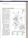
The Rover MEMS (Modular Engine
Management System) was developed jointly by
Rover and Motorola, and first appeared in 1989
on Montego 2.0 carburettor and then MPi
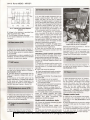
vehicles. MEMS is a fully-integrated system
that controls primary ignition, fuelling and idle
control from within the same ECM (see
illustration 14.1). When fitted to carburetted
engines, it is known as the ERICsystem.
MEMS was designed as a modular system
that was capable of controlling a wide range
of engines equipped with either MPi or SPi.
Additionally, the ECM is designed for a harsh
environment. It is robustly built, and
incorporates short-circuit
protection in
consideration of its location in the engine
compartment.
Prior to 19.94, there were three main
production versions of MEMS. These are
labelled versions 1.2, 1.3 and 1.6. From mid1994, version 1.8 was fitted.
The differences between the versions are
as follows:
Ba
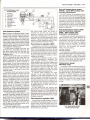
14.1 Rover MEMS(Rover214SPi).Multi-point systemsare very similar
1
2
3
4
5
6
7
8
Throttlepedal switch
Inertiaswitch
Fuelpump
TPS
Fuelpressure regulator
Fuelinjector
Stepper motor
ATS
9 Throttlebody heater (inlet
manifold)
10 CTS
11 Distributor
12 CAS
13 SO connector plug
14 ECM
15 Mainrelay
~-....
--
16 Fuelpump relay
17 Throttlebody heater
(inletmanifold)relay
18 Ignitioncoil
19 OS
20 OS relay
21 CFSV
22 Charcoalcanister
, -
~
:ec
...:=
....